JP2004202122A - Shower bathing device - Google Patents
Shower bathing device Download PDFInfo
- Publication number
- JP2004202122A JP2004202122A JP2002377774A JP2002377774A JP2004202122A JP 2004202122 A JP2004202122 A JP 2004202122A JP 2002377774 A JP2002377774 A JP 2002377774A JP 2002377774 A JP2002377774 A JP 2002377774A JP 2004202122 A JP2004202122 A JP 2004202122A
- Authority
- JP
- Japan
- Prior art keywords
- temperature
- hot water
- shower
- temperature sensor
- detected
- Prior art date
- Legal status (The legal status is an assumption and is not a legal conclusion. Google has not performed a legal analysis and makes no representation as to the accuracy of the status listed.)
- Withdrawn
Links
- 238000003287 bathing Methods 0.000 title claims abstract description 28
- XLYOFNOQVPJJNP-UHFFFAOYSA-N water Substances O XLYOFNOQVPJJNP-UHFFFAOYSA-N 0.000 claims abstract description 131
- 230000002401 inhibitory effect Effects 0.000 claims description 2
- 238000011010 flushing procedure Methods 0.000 claims 1
- 230000005856 abnormality Effects 0.000 abstract description 8
- 238000001514 detection method Methods 0.000 description 4
- 239000002453 shampoo Substances 0.000 description 4
- 238000004140 cleaning Methods 0.000 description 3
- 238000004891 communication Methods 0.000 description 3
- 239000007788 liquid Substances 0.000 description 3
- 238000005406 washing Methods 0.000 description 3
- 230000007423 decrease Effects 0.000 description 2
- 239000000645 desinfectant Substances 0.000 description 2
- 238000010586 diagram Methods 0.000 description 2
- 238000002347 injection Methods 0.000 description 2
- 239000007924 injection Substances 0.000 description 2
- 230000000474 nursing effect Effects 0.000 description 2
- 230000002159 abnormal effect Effects 0.000 description 1
- 238000007664 blowing Methods 0.000 description 1
- 230000000249 desinfective effect Effects 0.000 description 1
- 230000006866 deterioration Effects 0.000 description 1
- 230000000694 effects Effects 0.000 description 1
- 238000000034 method Methods 0.000 description 1
- 239000000203 mixture Substances 0.000 description 1
- 238000004659 sterilization and disinfection Methods 0.000 description 1
Images


Landscapes
- Bathtubs, Showers, And Their Attachments (AREA)
- Devices For Medical Bathing And Washing (AREA)
Abstract
Description
【0001】
【発明の属する技術分野】
本発明は、少なくともシャワー室に固定されたシャワーノズルから噴出される温水で、シャワー室内の被洗浄者を洗浄するシャワー入浴装置に関する。
【0002】
【従来の技術】
従来のシャワー入浴装置として、被洗浄者が内部に入るシャワー室を備えており、このシャワー室の内壁に複数のシャワーノズルが固定され、シャワー室内の被洗浄者の身体に向かって各シャワーノズルから温水が噴出し、被洗浄者の身体を洗浄するように構成されたものが知られている。
【0003】
このようなシャワー入浴装置では、快適な入浴感を得るためシャワーノズルから噴出される温水の湯温は入浴に適した湯温になるように制御される。そのため、湯温を検知する温度センサが取り付けられており、この温度センサが検出する湯温信号に基づいて湯温の制御を行うように構成されている(例えば、特許文献1参照)。
【0004】
【特許文献1】
特開2000−84030号公報(段落番号0011,0025、および図1の測温抵抗体7参照)
【0005】
【発明が解決しようとする課題】
従来のシャワー入浴装置では、温度センサの検知信号に基づいて湯温を制御しているので、温度センサに何らかの異常が生じ、入浴に適した温度から外れた湯温の温水が噴出されると、快適な入浴感を得ることができないという不具合が生じる。とくに、実際の湯温より低温を示す検知信号が温度センサから出力されるような異常が生じると、湯温を上昇させる制御を連続して行うので、快適な入浴感を得られる湯温より高温の温水が継続して噴出されるので、入浴者は快適な入浴感を得ることができない状態を長時間我慢しなければならないという不具合が生じる。
【0006】
そこで本発明は、上記の問題点に鑑み、このような不具合を解消することのできるシャワー入浴装置を提供することを課題とする。
【0007】
【課題を解決するための手段】
上記課題を解決するために本発明によるシャワー入浴装置は、シャワー室の内部に固定されたシャワーノズルから、シャワー室内の被洗浄者の身体に温水を噴出し身体を洗浄するシャワー入浴装置であって、温水の温度を検知する温度センサを有し、噴出される温水の温度を所定の温度に制御する温度制御手段を備えたものにおいて、上記温度センサの故障を検知し、温度センサが故障した場合に少なくとも高温の温水の噴出を禁止する噴出禁止手段を設けたことを特徴とする。
【0008】
このように噴出禁止手段を設けたので、温度センサが故障をした場合にもただちに少なくとも高温の温水の噴出を停止させ、快適ではない入浴状態が継続しないようにした。
【0009】
なお、上記温度センサの近くに第2温度センサを設け、この温度センサと第2温度センサの検出する湯水の温度差が所定範囲以上になった場合に上記温度センサの故障と検知し、上記噴出禁止手段を作動させてもよい。
【0010】
この場合、特に、前記温度センサと第2温度センサの検出する湯水の温度差を1℃以内とすることが望ましい。
【0011】
また、上記温度センサが検知する湯温が、湯温制御範囲より低温に設定された所定の温度以下になった場合に、上記噴出禁止手段を作動させてもよい。
【0012】
上記噴出禁止手段は温度センサの故障を報知することが望ましい。
【0013】
さらに、温度センサが検知する湯温が、湯温制御範囲より高温に設定された所定の温度以上になった場合、前記噴出禁止手段とは別個に、少なくとも高温の温水の噴出を禁止する副噴出禁止手段を設ければよい。
【0014】
【発明の実施の形態】
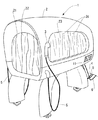
図1および図2を参照して、1は本発明によるシャワー入浴装置である。このシャワー入浴装置1は前方に開口21を有するシャワー室2を備えている。このシャワー室2内には図示しないが、天井に左右各々6個ずつ合計12個のシャワーノズルが取り付けられている。また、同じくシャワー室2の内底面には上方に向かって温水を噴出するように4個のシャワーノズルが取り付けられている。そして、これら16個のシャワーノズルには配管4を介して温水が供給される。
【0015】
一方、シャワー室2の左右側面には各々ハンドシャワー3が設けられている。両ハンドシャワー3には上記配管4とは別の配管5を介して温水が供給されるように構成されている。そして、配管4を介して供給される温水の温度と配管5を介して供給される温水の温度とは共にリモコン11を介して設定することができる。このリモコン11はシャワー室2の外側面に取り付けられており、後述するコントローラとの間で通信ケーブル6を介して相互に通信することができるものである。
【0016】
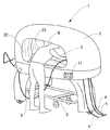
被洗浄者CはストレッチャSに寝たままの状態で足側からシャワー室2に入る。シャワー室には上述のように16個のシャワーノズルが固定されており、配管4を介して供給される温水を被洗浄者Cの身体に向かって噴出し被洗浄者Cの身体を洗浄する。
【0017】
シャワー室2の左右側面には介護用の窓23が設けられており、シャワーノズルから温水が噴出している間はカーテン22・24を閉めて開口21や介護窓23から飛沫がシャワー室外へ放出されないようにした。
【0018】
シャワーヘッドから噴出される温水による洗浄が終了すると、シャワー室2の外側で待機している洗浄者Nがハンドシャワー3を把持して介護窓23から上半身をシャワー室2内に入れて被洗浄者Cの身体を洗浄する。また、被洗浄者Cの頭部はシャワー室2内に入っていないので、ハンドシャワーを使って例えば被洗浄者Cの頭部洗浄や洗髪をすることができる。
【0019】
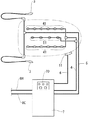
図3に示すように、シャワー室2から所定距離離れた位置に給湯制御装置7が設けられている。この給湯制御装置7には高温の温水が供給される給湯管8Hと冷水が供給される給水管8Cとが接続されている。そして、リモコン11もしくは操作パネル70によって設定された温度になるように高温の温水と冷水とを混合して配管4および配管5を介してシャワー室2の天井に取り付けられているシャワーノズル41と、シャワー室2の内底面に取り付けられているシャワーノズル51およびハンドシャワー3へと供給する。
【0020】
図4に示すように、給湯制御装置7には、操作パネル70および通信ケーブル6を介してリモコン11が接続された制御ユニット9が内蔵されている。この制御ユニット9は、不図示の公知の記憶手段に記憶されたプログラムと操作パネルやリモコンからの操作やサーモスタット等の各種センサからの入力に基づいて給湯制御装置を制御している。なお記憶手段には制御プログラムのほかシャワーの初期設定温度やシャワーの適正温度範囲やシャワーの噴射時間等が記憶されている。給湯管8Hおよび給水管8Cには各々電磁式の開閉バルブ71・72が取り付けられており、シャワー室2への給湯を開始する際に制御ユニット9によって両開閉バルブ71・72が開弁される。両開閉バルブ71・72を通過した高温の温水と冷水とは各々ミキシングバルブ73・74に到達する。
【0021】
両ミキシングバルブ73・74は共に制御ユニット9によって比例制御されるものであり、開閉バルブ71を通過した高温の温水と開閉バルブ72を通過した冷水とを混合して吐出するものである。なお、両ミキシングバルブ73・74は制御ユニット9によって相互に独立して制御され、したがって、ミキシングバルブ73から吐出される温水の温度とミキシングバルブ74から吐出される温水の温度とを個別に調節することができる。
【0022】
ミキシングバルブ73から吐出された温水は配管5を介してハンドシャワー3に供給される。ミキシングバルブ73を配管5に接続する内部配管51には内部配管51内の湯温を検出する2個のサーミスタ91・92が取り付けられている。これらサーミスタ91・92で検出された湯温データは制御ユニット9に入力され、ミキシングバルブ73がフィードバック制御される。
【0023】
また、何らかの異常が生じて予め設定された適正温度範囲外の湯温を検出すると開閉バルブ75をただちに強制的に閉弁させると共にドレン用の開閉バルブ79を開閉し、手適正温度範囲外の温度の温水をハンドシャワー3に供給させず、排水口90に排出するように設定されている。
【0024】
一方、ミキシングバルブ74と配管4とを連結する内部配管には同じくサーミスタ93・94が取り付けられており、制御ユニット9はこれらサーミスタ93・94からの検出温度に応じてミキシングバルブ74をフィードバック制御する。また、湯温が適正温度範囲を超えると上述の場合と同様に開閉バルブ76・77を強制的に閉弁させドレン用の開閉バルブ78を開弁するように構成されている。なお、95は圧力センサであり、内部配管41内の圧力を検出し、この検出された圧力によってミキシングバルブ74からの吐出量が一定になるようにフィードバック制御し、シャワーノズル41・51から常に一定の強さで温水が噴出するようにした。
【0025】
7Aはボディーシャンプー槽であり、制御ユニット9からの指令によりポンプ7A−2が作動すると、ボディーシャンプー液を内部配管41内に混入させ、シャワーノズル41・51からボディーシャンプーが混入された温水を噴出できるように構成している。7A−1は静電容量式の水位センサであり、ボディーシャンプーの液量が規定量以下に減少すると、制御ユニット9がその旨を制御パネル70やリモコン11に報知するようにした。
【0026】
隣接する7Bは消毒液槽であり、シャワー室2内に被洗浄者Cが入っていない状態でシャワーノズル41・51やハンドシャワー3から消毒液を噴出させ、シャワー室2内の消毒を行えるようにした。なお、ポンプ7B−2・7B−3は共に制御ユニット9により各々独立して制御される。また、7B−1は水位センサであり、消毒液の残量を検知するものである。
【0027】
ところで、内部配管41と配管4との間には開閉バルブ76・77が並列に接続されている。開閉バルブ76を通過する流量は開閉バルブ77を通過する流量より少なくなるように設定されている。シャワーノズル41・51から最初に温水を被洗浄者Cに対して噴出する際には、先に開閉バルブ76のみを開弁し、シャワーノズル41・51からの噴出勢いを弱くしていきなり強く噴出することにより被洗浄者Cが驚くことを防止するようにした。なお、一定時間が経過すると開閉バルブ77を開弁してシャワーノズル41・51から温水を勢いよく噴出させる。
【0028】
78はドレン用の開閉バルブであり、内部配管41内の湯温が設定された温度に到達されるまで等、温水の温度が快適な温度でない場合は、この開閉バルブ78を開弁し温水を排出する。そして内部配管41内の湯温が設定温度に達すると、この開閉バルブ78を閉弁させると共に、上述のように開閉バルブ76およびそのあと開閉バルブ77を開弁させるようにした。
【0029】
ところで、配管4を介してシャワーノズル41・51に供給される温水の温度は、制御ユニット9の記憶手段に記憶されたシャワーの初期設定温度に基づくが、制御パネル70やリモコン11によって温度を変更できる。この温度変更はあらかじめシャワーに適した範囲内(例えば38℃から42℃の間)で設定可能となっている。また、ハンドシャワー3に供給される温水の温度は、これとは別に制御パネル70やリモコン11によって設定可能であるが、共通の温度としてもよく、あるいは制御ユニット9はシャワーノズル41・51から噴出される温水の温度が設定されると、自動的にその設定温度より所定温度低い温度をハンドシャワー3に供給される温度として設定しても良い。
【0030】
このシャワーノズル41・51とハンドシャワー3の温度差は予め設定されており、例えば2℃であるとすると、シャワーノズル41・51からの噴出温度を42℃に設定すると、ハンドシャワー3からの噴出温度は自動的に40℃に設定される。なお、ハンドシャワー3の噴出温度が自動的に設定されたあと、マニュアル操作でハンドシャワー3の噴出温度を変更できるように構成してもよい。
【0031】
ところで、配管4および配管5には上述のように、サーミスタ93・94およびサーミスタ91・92が取り付けられており、配管4および配管5内を流れる温水の湯温を検知している。これら4個のサーミスタは共に負特性を有しており、低温では比較的抵抗値が高く、検知する温度が上昇するにしたがって抵抗値が減少する。
【0032】
図5を参照して、配管4を例に説明すると、配管4を流れる温水の温度はサーミスタ93・94により常時検知されている。両サーミスタ93・94からの検知信号は制御ユニット9内のマイコン9aに入力され、この検知信号と制御ユニット9内の記憶手段(不図示)に記憶される制御プログラムに基づいてシャワーへの温水の供給が制御される。
【0033】
なお、この不図示の記憶手段には、前記検知された温度と比較する3種の温度データが記憶されており、ひとつは湯水の設定温度T1で、2つ目は検知された温度が適正温度範囲内にあるか判断するための第1上限温度Thおよび第1下限温度Tlで、3つ目はサーミスタの故障を判断するための第2上限温度THおよび第2下限温度TLである。なお、設定温度T1は操作パネルからの変更がなければシャワー装置起動時に取得される初期設定温度40℃であり、第1の上限温度Thは43℃、第1のTl下限温度は36℃であり、第2の上限温度THは50℃、下限温度TLは0℃として記憶されている。なお、この判断温度は本実施形態に限定されるものではない。
【0034】
湯温の制御にはサーミスタ93で検知された湯温データを用いる。サーミスタ94で検知された湯温データはサーミスタ93で検知された湯温データと比較するためのもので、両湯温データの差が所定の値(ここでは1℃)を超えるといずれか一方のサーミスタに異常が生じたのもとして、トランジスタ9bを介して開閉バルブ76・77を閉弁し温水が配管4を介してシャワーノズル41・51に供給されないようにした。
【0035】
また10aは比較回路を備えた副射出禁止回路であり、可変抵抗器10bによって設定される基準電圧とサーミスタ93の抵抗値によって規定される電圧とを比較し、サーミスタ93側の電圧が基準電圧より高くなるとトランジスタ10bをオフにするように構成した。
【0036】
このトランジスタ10bには同じく開閉バルブ76・77が接続されており、トランジスタ10bがオフになるとこれら開閉バルブ76・77が閉弁し、温水が配管4を介してシャワーノズル41・51に供給されないようにした。
【0037】
図6を参照して、マイコン9aによる制御プログラムの一部を説明する。洗浄者によってシャワー装置が起動されると、まずサーミスタ93より検知された温度Taとサーミスタ94より検知された温度Tbと比較する(S1、S2)。TaとTbの温度差が1℃以内であればサーミスタ93は正常に動作していると判断し、続いて、設定温度T1と温度Taとを比較する(S3)。設定温度T1は操作パネルからの温度の変更が無ければ初期値として記憶されている温度(40℃)を読み出し設定温度する。最初は湯温Taが適温に達していないので排水処理(S21)が実行される。具体的には開閉バルブ76,77が閉弁され、ドレン用の開閉バルブ78を開弁して排水しつつミキシングバルブ74を開いて湯温を適温まで上昇させる。続いて、検知された温度Taが設定温度T1に達したら開閉バルブ78を閉弁して排水を停止させ(S4)スタンバイ状態となる(S5)。
【0038】
つぎにシャワー入浴開始キーが押されると(S5、S6)、サーミスタ93より湯温Taを検知し、サーミスタ94より検知された温度Tbと比較する(S7、S8)。TaとTbの温度差が1℃以内であればサーミスタ93は正常に動作していると判断し(S8)、そうでなければサーミスタ93・94の異常と判断してシャワーノズル41,51からの温水の噴出を停止すると共にアラームを作動させ(S19)、更に所定のエラーシーケンスを実行する(S20)。
【0039】
続いて、湯温Taが第1下限温度Tlと第1上限温度Thの範囲内であるか、つまり適正温度範囲内にあるか判断し(S9)、範囲内であれば開閉バルブ76,77が順次開いて滑らかにシャワーが噴出される(S10)。この状態で、検知される湯温Taが設定温度T1より低い温度か(S11)あるいは高い温度であるかを判断し(S13)、低い場合はミキシングバルブ74の温水側の開度を1ステップ増加させ、湯温を上昇させ(S12)、高い場合はミキシングバルブ74の温水側の開度を1ステップ減少し湯温を下降させ(S14)、所定のシャワー時間あるいはシャワー停止入力がされるので湯温を設定温度T1に保つようにしている(S15、S16)。
【0040】
本実施の形態では温度センサとしてサーミスタを使用しており、そのためサーミスタに断線故障が生じると抵抗値が無限大になり、きわめて低温度を検知した場合と同じ状態になる。したがって、S9において湯温Taが適正温度(Tl−Th)範囲外と判断された後に、湯温Taが第2下限温度TLと第2上限温度THの範囲内にあるか判断し(S17)、ここでサーミスタ93とサーミスタ94が同時に断線し、S8で温度差が無く「異常なし」と判断されていたとしても、湯温TaがTLより低温であれば、サーミスタ93・94に断線故障が生じていると判断することができる。故障と判断した場合はシャワーノズル41,51からの温水の噴出を停止すると共にアラームを作動させ(S19)、更に所定のエラーシーケンスを実行(エラー表示等)する(S20)。
【0041】
なお、サーミスタがショートすると抵抗値はゼロになり、きわめて高温を検知した場合と同じになる。そのため、サーミスタ93、94が動じにショートした場合、実際の湯温が適温でも検知されるTaが予め設定された高温度THを超えるので(S17)シャワーノズル41,51からの温水の噴出を停止すると共にアラームを作動させ(S19)、更に所定のエラーシーケンスを実行する(S20)。なおS17において湯温TaがTL−THの範囲内にあるなら、湯温が適正温度の範囲を超えたので、排水処理(S18)を行いながら湯温を調節し、適正温度範囲内となったらS7に戻り再びシャワーが噴出を開始する。
【0042】
そして、この図6に示した制御シーケンスはハンドシャワー3に供給される温水の温度制御についても適用されることが望ましい。ただし、ハンドシャワー3は常に洗浄者Nが把持して使用するので、噴出される温水が適温に到達するまでの間でもハンドシャワー3から噴出させても洗浄者Nが湯温をチェックするので問題は生じない。
【0043】
ところで、上記実施の形態では、S8におけるサーミスタ93とサーミスタ94による湯温Taと湯温Tbの温度差比較と、S17における湯温Taが第2下限温度TLと第2上限温度THの範囲内にあるかによってサーミスタの故障を判断しているが、いずれか一方の判断によって行ってもよく、また故障の判断方法はこれらに限定されるものではない。また温度差比較はサーミスタの位置をできるだけ近くに配置し、その温度差はできるだけ狭くすることが望ましい。この温度差が1℃以内であればサーミスタの劣化を早期に発見できその影響を最小限とすることができる。なお、その温度差は0.5℃以内であればより望ましい。
【0044】
また、上記実施の形態では、図6に示すS8やS17の処理でサーミスタの故障を検知した場合、マイコン9aは開閉バルブ76・77を閉弁し設定された温度以上の湯温をシャワーノズル41,51へ供給しないように設定されているが、開閉バルブ76・77ではなく例えば高温側の開閉バルブ71を閉弁させ、所定温度以上の温水が配管5を介してシャワーノズルに供給されないように設定しても良い。
【0045】
【発明の効果】
以上の説明から明らかなように、本発明は、とくにシャワーノズルから噴出される温水の湯温を検知する温度センサに異常が生じた際に、快適な入浴感が得られる湯温から外れた温度の温水が噴出され続けることを防止することができ、被洗浄者に不快な思いをさせることがない。
【図面の簡単な説明】
【図1】本発明の一実施の形態の構成を示す図
【図2】被洗浄者を洗っている状態を示す図
【図3】シャワー入浴装置内の配管状態を示す図
【図4】温水制御装置内の構成を示す図
【図5】噴出禁止手段の構成を示す図
【図6】マイコン内での湯温制御プログラムの一部を示すフロー図
【符号の説明】
1 シャワー入浴装置
11 リモコン
2 シャワー室
3 ハンドシャワー
4 配管
41 シャワーノズル
5 配管
51 シャワーノズル
6 通信ケーブル
7 温水制御装置
73 ミキシングバルブ
74 ミキシングバルブ
8H 給湯管
8C 給水管
9 制御ユニット[0001]
TECHNICAL FIELD OF THE INVENTION
The present invention relates to a shower bathing device that cleans a person to be cleaned in a shower room with at least warm water jetted from a shower nozzle fixed to the shower room.
[0002]
[Prior art]
As a conventional shower bathing device, a shower room into which a person to be cleaned enters is provided, and a plurality of shower nozzles are fixed to the inner wall of the shower room, and each shower nozzle is directed toward the body of the person to be cleaned in the shower room. 2. Description of the Related Art There is known an apparatus in which warm water is blown out to wash a body of a person to be washed.
[0003]
In such a shower bathing apparatus, the temperature of the hot water spouted from the shower nozzle is controlled so as to be suitable for bathing in order to obtain a comfortable bathing feeling. Therefore, a temperature sensor for detecting the temperature of the hot water is provided, and the temperature of the hot water is controlled based on a signal of the hot water temperature detected by the temperature sensor (for example, see Patent Document 1).
[0004]
[Patent Document 1]
Japanese Patent Application Laid-Open No. 2000-84030 (see paragraphs 0011 and 0025 and the
[0005]
[Problems to be solved by the invention]
In the conventional shower bathing device, since the temperature of the hot water is controlled based on the detection signal of the temperature sensor, some abnormality occurs in the temperature sensor, and when hot water having a temperature outside the temperature suitable for bathing is ejected, There is a problem that a comfortable bathing feeling cannot be obtained. In particular, when an abnormality occurs in which a detection signal indicating a temperature lower than the actual hot water temperature is output from the temperature sensor, the control for increasing the hot water temperature is continuously performed. Since the warm water is continuously spouted out, there is a problem that the bather must endure a state in which a comfortable bathing feeling cannot be obtained for a long time.
[0006]
In view of the above problems, an object of the present invention is to provide a shower bathing device that can solve such a problem.
[0007]
[Means for Solving the Problems]
A shower bathing device according to the present invention for solving the above-mentioned problems is a shower bathing device for washing a body by blowing out hot water from a shower nozzle fixed inside a shower room to a body of a person to be cleaned in the shower room. A temperature sensor for detecting the temperature of the hot water, and a temperature control means for controlling the temperature of the hot water to be ejected to a predetermined temperature. And a jet prohibition means for prohibiting jetting of at least high-temperature hot water.
[0008]
Since the ejection prohibiting means is provided in this way, even when the temperature sensor fails, the ejection of at least high-temperature hot water is immediately stopped, so that an uncomfortable bathing state is not continued.
[0009]
A second temperature sensor is provided near the temperature sensor. When the temperature difference between the temperature sensor and the hot water detected by the second temperature sensor exceeds a predetermined range, it is detected that the temperature sensor has failed, and The prohibition means may be activated.
[0010]
In this case, it is particularly desirable that the temperature difference between the hot and cold water detected by the temperature sensor and the second temperature sensor be within 1 ° C.
[0011]
Further, when the hot water temperature detected by the temperature sensor becomes equal to or lower than a predetermined temperature set lower than the hot water temperature control range, the ejection prohibiting means may be operated.
[0012]
It is desirable that the ejection prohibiting means reports a failure of the temperature sensor.
[0013]
Further, when the temperature of the hot water detected by the temperature sensor becomes equal to or higher than a predetermined temperature set to be higher than the hot water temperature control range, separately from the jetting prohibiting means, at least a sub-spout prohibiting the jetting of high-temperature hot water. Prohibition means may be provided.
[0014]
BEST MODE FOR CARRYING OUT THE INVENTION
1 and 2,
[0015]
On the other hand, a
[0016]
The person C to be cleaned enters the
[0017]
[0018]
When the washing with the warm water spouted from the shower head is completed, the washing person N waiting outside the
[0019]
As shown in FIG. 3, a hot water
[0020]
As shown in FIG. 4, hot water
[0021]
Both mixing
[0022]
The hot water discharged from the mixing
[0023]
Further, if any abnormality occurs and a hot water temperature outside the preset proper temperature range is detected, the on-off
[0024]
On the other hand, the
[0025]
[0026]
An adjoining 7B is a disinfectant bath, in which the disinfectant is ejected from the
[0027]
Incidentally, open /
[0028]
[0029]
By the way, the temperature of the hot water supplied to the
[0030]
The temperature difference between the
[0031]
By the way, the
[0032]
Referring to FIG. 5 and taking the
[0033]
The storage means (not shown) stores three kinds of temperature data to be compared with the detected temperature. One is the set temperature T1 of hot and cold water, and the other is the detected temperature is the appropriate temperature. A first upper limit temperature Th and a first lower limit temperature Tl for judging whether the temperature is within the range, and a third upper limit temperature TH and a second lower limit temperature TL for judging a failure of the thermistor. The set temperature T1 is an initial set temperature of 40 ° C. obtained when the shower device is started unless there is a change from the operation panel, the first upper limit temperature Th is 43 ° C., and the first Tl lower limit temperature is 36 ° C. , The second upper limit temperature TH is stored as 50 ° C., and the lower limit temperature TL is stored as 0 ° C. Note that this determination temperature is not limited to the present embodiment.
[0034]
For controlling the hot water temperature, the hot water temperature data detected by the
[0035]
[0036]
Opening / closing
[0037]
With reference to FIG. 6, a part of a control program by the
[0038]
Next, when the shower bathing start key is pressed (S5, S6), the hot water temperature Ta is detected by the
[0039]
Subsequently, it is determined whether the hot water temperature Ta is within the range between the first lower limit temperature Tl and the first upper limit temperature Th, that is, within the appropriate temperature range (S9). The shower is sequentially opened and the shower is spouted smoothly (S10). In this state, it is determined whether the detected hot water temperature Ta is lower than the set temperature T1 (S11) or higher (S13). If it is lower, the opening of the mixing
[0040]
In the present embodiment, a thermistor is used as a temperature sensor. Therefore, if a disconnection failure occurs in the thermistor, the resistance value becomes infinite, and the state becomes the same as when a very low temperature is detected. Therefore, after the hot water temperature Ta is determined to be out of the appropriate temperature (Tl-Th) range in S9, it is determined whether the hot water temperature Ta is within the range of the second lower limit temperature TL and the second upper limit temperature TH (S17). Here, even if the
[0041]
When the thermistor is short-circuited, the resistance value becomes zero, which is the same as when extremely high temperature is detected. Therefore, when the
[0042]
The control sequence shown in FIG. 6 is desirably applied to the temperature control of the hot water supplied to the
[0043]
By the way, in the above embodiment, the temperature difference between the hot water temperature Ta and the hot water temperature Tb by the
[0044]
Further, in the above embodiment, when the failure of the thermistor is detected in the processing of S8 and S17 shown in FIG. 6, the
[0045]
【The invention's effect】
As is apparent from the above description, the present invention provides a temperature that deviates from the hot water temperature at which a comfortable bathing feeling can be obtained, particularly when an abnormality occurs in the temperature sensor that detects the hot water temperature spouted from the shower nozzle. Can be prevented from continuing to be spouted out, and the person to be cleaned is not uncomfortable.
[Brief description of the drawings]
FIG. 1 is a view showing a configuration of an embodiment of the present invention; FIG. 2 is a view showing a state in which a person to be washed is being washed; FIG. 3 is a view showing a pipe state in a shower bathing apparatus; FIG. FIG. 5 is a diagram showing a configuration of a control device. FIG. 5 is a diagram showing a configuration of an ejection inhibiting means. FIG. 6 is a flowchart showing a part of a hot water temperature control program in a microcomputer.
DESCRIPTION OF
Claims (6)
Priority Applications (1)
| Application Number | Priority Date | Filing Date | Title |
|---|---|---|---|
| JP2002377774A JP2004202122A (en) | 2002-12-26 | 2002-12-26 | Shower bathing device |
Applications Claiming Priority (1)
| Application Number | Priority Date | Filing Date | Title |
|---|---|---|---|
| JP2002377774A JP2004202122A (en) | 2002-12-26 | 2002-12-26 | Shower bathing device |
Publications (1)
| Publication Number | Publication Date |
|---|---|
| JP2004202122A true JP2004202122A (en) | 2004-07-22 |
Family
ID=32814848
Family Applications (1)
| Application Number | Title | Priority Date | Filing Date |
|---|---|---|---|
| JP2002377774A Withdrawn JP2004202122A (en) | 2002-12-26 | 2002-12-26 | Shower bathing device |
Country Status (1)
| Country | Link |
|---|---|
| JP (1) | JP2004202122A (en) |
Cited By (3)
| Publication number | Priority date | Publication date | Assignee | Title |
|---|---|---|---|---|
| JP2007202781A (en) * | 2006-02-01 | 2007-08-16 | Toto Ltd | Shower bath device |
| US8413615B2 (en) | 2007-12-19 | 2013-04-09 | Rinnai Corporation | Hot water supply apparatus |
| JP2019037533A (en) * | 2017-08-25 | 2019-03-14 | オージー技研株式会社 | Bathing equipment |
-
2002
- 2002-12-26 JP JP2002377774A patent/JP2004202122A/en not_active Withdrawn
Cited By (5)
| Publication number | Priority date | Publication date | Assignee | Title |
|---|---|---|---|---|
| JP2007202781A (en) * | 2006-02-01 | 2007-08-16 | Toto Ltd | Shower bath device |
| US8413615B2 (en) | 2007-12-19 | 2013-04-09 | Rinnai Corporation | Hot water supply apparatus |
| CN101464051B (en) * | 2007-12-19 | 2013-04-17 | 林内株式会社 | Hot water supply apparatus |
| JP2019037533A (en) * | 2017-08-25 | 2019-03-14 | オージー技研株式会社 | Bathing equipment |
| JP7012995B2 (en) | 2017-08-25 | 2022-01-31 | オージー技研株式会社 | Bathing equipment |
Similar Documents
| Publication | Publication Date | Title |
|---|---|---|
| JP4570613B2 (en) | Method for controlling water supply in a sanitation facility | |
| EP3305998A2 (en) | Electronic toilet capable of implementing switching between cold water and hot water, and control method | |
| JP2019065476A (en) | Sanitary washing device | |
| JP2004202122A (en) | Shower bathing device | |
| JP2006333909A (en) | Automated bathroom-washing apparatus | |
| JPH07150607A (en) | Sanitary washing device | |
| JP4075122B2 (en) | Bathtub cleaning equipment | |
| JP4601767B2 (en) | Air shower equipment | |
| KR20180028694A (en) | Bidet having sitz bath function and method for controlling the bidet | |
| JP4075123B2 (en) | Bathtub cleaning equipment | |
| JP2019065478A (en) | Sanitary washing device | |
| JP3509089B2 (en) | Automatic washing tub | |
| JP2559308B2 (en) | Bath equipment | |
| JPH0475618A (en) | Shower equipment | |
| JP2004041589A (en) | Shower bathing apparatus | |
| JPH10267400A (en) | Bath device | |
| KR102869534B1 (en) | Bathtub equipped with hinged door | |
| KR102869535B1 (en) | Bathtub equipped with hinged door | |
| JP7424329B2 (en) | Bathtub cleaning system, hot water supply system and bathtub cleaning control method | |
| KR200353189Y1 (en) | Hydro Bathub | |
| JP7358285B2 (en) | bathroom faucet system | |
| JPH0626236Y2 (en) | Bathtub system | |
| JP2001355912A (en) | Bathtub controlling system | |
| JP2005046259A (en) | Hot and cold water supplying device for shower bathing device | |
| CN116919218A (en) | Control method, control device, sitting shower and storage medium |
Legal Events
| Date | Code | Title | Description |
|---|---|---|---|
| A521 | Written amendment |
Free format text: JAPANESE INTERMEDIATE CODE: A821 Effective date: 20041101 |
|
| A711 | Notification of change in applicant |
Free format text: JAPANESE INTERMEDIATE CODE: A711 Effective date: 20041101 |
|
| RD02 | Notification of acceptance of power of attorney |
Free format text: JAPANESE INTERMEDIATE CODE: A7422 Effective date: 20041101 |
|
| A521 | Written amendment |
Free format text: JAPANESE INTERMEDIATE CODE: A821 Effective date: 20041101 |
|
| A300 | Withdrawal of application because of no request for examination |
Free format text: JAPANESE INTERMEDIATE CODE: A300 Effective date: 20060307 |