【0001】
【発明の属する技術分野】
本発明はメラミンフォームを用いたクリーナーに関する。
【0002】
【従来の技術】
従来のメラミンフォームにおいては、その材質的な脆さが問題とされ、加熱圧縮などの製造上の工夫(特許公開2002−59443)がなされてきたが、引っ張り力に弱く破れやすいメラミンフォームの弱点がまだ十分に解消されたとは言い難かった。
【0003】
【発明が解決しようとする課題】
そのため、従来のメラミンフォームにおいては小さくカットしたものがそのまま用いられ、洗剤いらずの優れた特性にもかかわらず、用途の範囲が限られるという問題があった。
【0004】
本発明は引っ張り力に弱く破れやすいメラミンフォームの弱点を補い、その洗剤いらずの特性を生かして用途の範囲を広げるとともに、曲面への密着性と追従性に優れたホルダーを有するクリーナーを提供することを目的としている。
【0005】
【課題を解決するための手段】
上記目的を達成するために、本発明におけるクリーナーにおいては、裏面がほぼ球面又は湾曲面をなして窪んだ吸盤型又は寄せ棟型又は切り妻屋根型のホルダー1に板状のメラミンフォーム7を組み合わせ、その中心部又は中心線上をホルダー1裏面に圧縮係止して面的に保持してある。
【0006】
【発明の実施の形態】
発明の実施の形態を実施例にもとづき図面を参照して説明する。
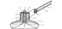
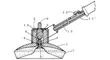
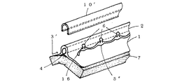
図1〜5に示すホルダー1は、その上面に、縦横いずれかの貫通孔3、3′を有するノブ2を設けて弾力性を有する軟質の合成樹脂で吸盤型又は寄せ棟型又は切り妻屋根型に成型し、裏面に球面又は湾曲面を形成して適度に窪ませる。ホルダー1の平面形状は円形、方形に限らない。張り出したスカート状又は屋根状の部分は中心部から周縁部乃至辺縁部にかけて徐々に肉薄に形成し、メラミンフォーム7を取り付けて押しつけた力がほぼ均一にかかるようにする。図1に示す実施例の場合はノブ2にホルダー1裏面に達する縦型の貫通孔3を設け、その上部開口部をすぼめて係止部4を形成し、図2〜4に示す実施例の場合は該貫通孔3下部の開口部をすぼめて係止部4を形成して、前者に長ピン5、後者に短ピン5′又は解除ピン9と対をなす短ピン5′を組み合わせる。図5に示す実施例の場合はノブ2に横方向への貫通孔3′を設け、ホルダー1裏面から該貫通孔3′に通じる係止部4を形成して短ピン5′又は連ピン5″を組み合わせる。係止部4は円形のツバ状又は直線的なボタン穴状にホルダー1と一体に形成し、長短のピン5、5′又は連ピン5″に押し広げられて小球状体6を受け入れたのち、くびれの部分に嵌合して係止するようにする。ホルダー1裏面に位置する貫通孔3又は係止部4の入り口は、いずれも係止されたピン頭が突出しないように適宜窪ませる。ノブ2を別体に設けてホルダー1に嵌め込んでもよい。
【0007】
メラミンフォーム7はホルダー1の平面形状より一回り大きい適切な形状の板状に成形し、中央部又は中心線上に単数又は複数の十字形のスリット8を設ける。該スリット8は一文字の切れ目又は小穴でもよい。スリット8を見分けるにはメラミンフォーム7を軽く折り曲げてみればよい。
【0008】
図1に示す実施例の長ピン5は軸の先端がくびれて小球状体6をなす有頭の押しピン型に硬質の適切な合成樹脂で成型し、頭部は上面が窪んだ皿形に形成する。長ピン5を用いてメラミンフォーム7をホルダー1に取り付けるときは、十字形のスリット8又は小穴にピン軸を通してからメラミンフォーム7を平らな面に置き、ホルダー1裏面の貫通孔3の開口部に軸先端を差し込んでホルダー1をメラミンフォーム7に押しつければ、メラミンフォーム7を圧縮係止しながら軸先端が貫通孔3上部の係止部4に嵌合し、小球状体6を露出させる。取り外すときは小球状体6を押し込めばよい。長ピン5は主として反復使用を目的とするが、使い切りとしてもよい。軸の付け根は適宜細めてもよい。
【0009】
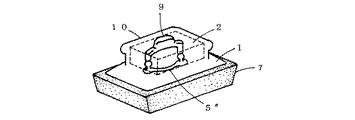
図2〜5に示す短ピン5′と連ピン5″は、皿形の頭部から直にくびれて小球状体6をなす小型の押しピン型に硬質の適切な合成樹脂で成型する。連ピン5″は適切な間隔を置いて複数個の短ピン5′の頭部と頭部を細帯状の連結部で連結し、一体に設ける。短ピン5′又は連ピン5″は使用時に取り付けてもよいが、あらかじめ十字形のスリット8又は小穴を設けた板状のメラミンフォーム7に埋設し、メラミンフォーム7とともに使い切りとすることが望ましい。短ピン5′又は連ピン5″を埋設したメラミンフォーム7を取り付けるときは、該メラミンフォーム7を平らな面に置き、そのほぼ中央に図2〜4のいずれかに示すホルダー1をあてがって押しつければ、ホルダー1に押されてメラミンフォーム7の中心部が陥没し、小球状体6が露出して下降していた解除ピン9を押し上げながら貫通孔3、3′下部又は底辺に形成された係止部4に嵌合し、メラミンフォーム7をホルダー1裏面に圧縮係止する。取り外すときは、解除ピン9を押し込めば使い切ったメラミンフォーム7とともに短ピン5′が押し出される。図5の実施例の場合は取り付け方は同じだが、取り外すときはピン頭にタブ16を設けてつまみ取り口とするか、連ピン5″の連結部をつまみ取り口とする。
【0010】
メラミンフォーム7は中央部又は中心線上を圧縮係止されて漏斗状又は連続した漏斗状に窪まされるが、使用時は圧縮されてほぼ平坦になり、ホルダー1によって面的に保持され、すり減ってもホルダー1裏面に張り付いて横ずれと引っ張り力による破断を防止される。メラミンフォーム7は絶えず摩耗し続けるので、流水で洗い流せば常に清潔感を保てる。本品は消耗品なので、別に補充品を用意する。
【0011】
図2〜4に示す解除ピン9は硬質の適切な合成樹脂で、一端の径が段差をなしてやや細まったスピンドル状に成型し、細まった部分が上面に突き出るようにして上下動自在に貫通孔3に挿入し、別に設ける穴あきのカバー10をノブ2に嵌め込んで抜け止めとする。解除ピン9のもう一端は係止された短ピン5′の小球状体6に当接する。連ピン5″と組み合わせる場合は連結させてもよい。
【0012】
図1〜5に示す実施例のカバー10とUチャンネル10′は、金属又は硬質の樹脂などで別に成型し、前述の解除ピン9の抜け止めとしたり、ノブ2に剛性を持たせたり、持ちやすくしたり、ハンドル11、11′を取り付けるときにノブ2に嵌め込んで用いるようにする。
【0013】
図4に示す実施例は、吸盤型の類型とも言うべき寄せ棟型のホルダー1に連ピン5″を組み合わせ、解除ピン9を連結して設けて手持ち用としてある。図では平面形状が長方形をなす形に設けられているが、長円形や楕円形としてもよい。
【0014】
図5に示す実施例は、切り妻屋根型のホルダー1の上面に棟型のノブ2を設け、Uチャンネル10′を組み合わせてある。本実施例は小型にして手持ち用としても、横長のスクレーパー型にしてガラス拭き用や広い面積用としてもよい。
【0015】
図1に示すハンドル11は、ハンドル11自体を中空軸14として、該中空軸14の先端にノズル15を設け、水をかけながら作業をしたりすすぎができるようにして、カバー10の側面に軸穴又は回動軸を設けて図1〜5に示すホルダー1に回動自在に取り付ける。ノズル15はわずかに下向きに角度をつけて設け、すすぎの際に上方へ跳ね上げたホルダー1に水がかからないようにする。
【0016】
図2に示すハンドル11′は、解除ピン9を設けたホルダー1や短ピン5′又は連ピン5″を埋設したメラミンフォーム7と組み合わせ、主にトイレ用として用いることを目的とする。ハンドル11′は軸内又は軸裏に貫通孔又は溝を設けてスライド式のロッド13を取り付け、手元のレバー12で押し出せるようにして、解除ピン9を設けたホルダー1に回動自在に取り付ける。ハンドル11′の取り付けには、側面に軸穴又は回動軸を設けたカバー10を用いる。また取り付け部には、ハンドル11′がホルダー1に対して鉛直をなす位置でロックされるように、やや強めのクリックを設ける。ハンドル11′のロック、ロック解除は、ホルダー1を適当な物に押し当ててハンドル11′の角度を変えることによって行い、使い切ったメラミンフォーム7を取り外すときは、ハンドル11′を鉛直に立ててロックさせ、ホルダー1を浮かした状態でレバー12をスライドさせてロッド13を押し出し、解除ピン9を押し込めばよい。ロッド13は手動で出し入れしてもよいが、バネなどで自動的に引っ込むようにするとなおよい。ピンを埋設した新しいメラミンフォーム7を取り付けるには、ハンドル11′を鉛直に立てて上述の項(
【0009】)で説明した要領でホルダー1を押しつければよいので、着脱に際しては不潔な部分にいっさい触れずにすむ(図3参照)。該ハンドル11′を図1に示す実施例のホルダー1に取り付けてもよい。
【0017】
図1〜5に示す実施例のクリーナーを手持ちとする場合はノブ2自体を取っ手とし、高所用やトイレ用とする場合はハンドル11、11′を取り付ける。
【0018】
本発明のホルダー1を他の発泡体や不織布などに用いることも可能である。
【0019】
【発明の効果】
本発明は以上のように構成されているので、以下に記載されるような効果を奏する。
【0020】
板状のメラミンフォーム7を圧縮係止して面的に保持することにより、引っ張り力に弱く破れやすいメラミンフォーム7の弱点が補われ、洗剤いらずの特性が生かされて浴室用やトイレ用などとして用途の範囲が広がる。
【0021】
弾力性を有するホルダー1により、曲面への追従性と密着性に優れ、浴槽内の四隅や便器の隠れた部分に柔軟に対応する。
【0022】
ハンドル11、11′が設けられていることにより、作業が効率的になり、不潔な部分に触れずに摩耗したメラミンフォーム7の交換ができる。
【0023】
【図面の簡単な説明】
【図1】本発明の長ピンを用いた吸盤型のホルダーの実施例を示す縦断面図である。
【図2】本発明の短ピンを用いた解除ピンを有する吸盤型のホルダーの実施例を示す縦断面図である。
【図3】本発明の短ピンを埋設したメラミンフォームと解除ピンを有する吸盤型のホルダーの実施例を示す縦断面図である。
【図4】本発明の寄せ棟型のホルダーの実施例を示す斜視図(一部透視図)である。
【図5】本発明の切り妻屋根型のホルダーの実施例を示す斜視図(一部透視図)である。
【符号の説明】
1 ホルダー
2 ノブ
3 縦型の貫通孔
3′横型の貫通孔
4 係止部
5 長ピン
5′短ピン
5″連ピン
6 小球状体
7 メラミンフォーム
8 スリット
9 解除ピン
10 カバー
10′Uチャンネル
11 ノズル付きのハンドル
11′ロッド付きのハンドル
12 レバー
13 ロッド
14 中空軸
15 ノズル
16 タブ[0001]
TECHNICAL FIELD OF THE INVENTION
The present invention relates to a cleaner using melamine foam.
[0002]
[Prior art]
In the conventional melamine foam, its material brittleness is considered to be a problem, and manufacturing contrivances such as heat compression (Patent Publication No. 2002-59443) have been made. It was hard to say that it was sufficiently resolved.
[0003]
[Problems to be solved by the invention]
For this reason, conventional melamine foams are used as they are, which are cut small, and there is a problem that the range of applications is limited despite excellent properties without using a detergent.
[0004]
The present invention compensates for the weakness of melamine foam which is weak to tensile force and easily breaks, and provides a cleaner having a holder with excellent adhesion to curved surfaces and excellent followability while making use of its detergent-free characteristics to expand the range of applications. It is intended to be.
[0005]
[Means for Solving the Problems]
In order to achieve the above object, in the cleaner of the present invention, a plate-shaped melamine foam 7 is combined with a sucker-type or ridge-type or gable-roof-type holder 1 having a substantially spherical or curved concave back surface. The central portion or the center line is compression-locked to the back surface of the holder 1 and is held in a planar manner.
[0006]
BEST MODE FOR CARRYING OUT THE INVENTION
Embodiments of the present invention will be described based on examples with reference to the drawings.
The holder 1 shown in FIGS. 1 to 5 is provided with a knob 2 having through holes 3 and 3 'in either the vertical or horizontal direction on its upper surface, and is made of a soft synthetic resin having elasticity, a suction cup type or a ridge type or a gable roof. It is molded into a mold, and a spherical surface or a curved surface is formed on the back surface to make it appropriately concave. The planar shape of the holder 1 is not limited to a circle or a square. The protruding skirt-like or roof-like portion is formed gradually thinner from the center portion to the peripheral portion to the peripheral portion so that the force applied by pressing the melamine foam 7 is applied substantially uniformly. In the case of the embodiment shown in FIG. 1, the knob 2 is provided with a vertical through-hole 3 reaching the back surface of the holder 1, and the upper opening thereof is narrowed to form a locking portion 4. In this case, the locking portion 4 is formed by narrowing the opening at the lower portion of the through-hole 3, and the long pin 5 is combined with the short pin 5 'or the short pin 5' paired with the release pin 9 as the latter. In the case of the embodiment shown in FIG. 5, the knob 2 is provided with a through hole 3 'in the lateral direction, and a locking portion 4 is formed from the back of the holder 1 to the through hole 3' to form the short pin 5 'or the connecting pin 5'. The locking portion 4 is formed integrally with the holder 1 in the shape of a circular brim or a straight button hole, and is pushed out by long and short pins 5, 5 'or continuous pins 5 "to form a small spherical body 6. After receiving the above, it is fitted and locked to the constricted portion. The entrance of the through hole 3 or the locking portion 4 located on the back surface of the holder 1 is appropriately depressed so that the locked pin heads do not protrude. The knob 2 may be provided separately and fitted into the holder 1.
[0007]
The melamine foam 7 is formed into a plate having an appropriate shape slightly larger than the planar shape of the holder 1 and provided with one or more cross-shaped slits 8 at the center or on the center line. The slit 8 may be a cut or small hole of one character. In order to identify the slit 8, the melamine foam 7 may be slightly bent.
[0008]
The long pin 5 of the embodiment shown in FIG. 1 is molded into a headed push pin type in which the tip of the shaft is constricted to form a small spherical body 6 with a suitable hard synthetic resin, and the head has a dish shape with a concave upper surface. Form. When attaching the melamine foam 7 to the holder 1 using the long pin 5, the melamine foam 7 is placed on a flat surface after passing the pin shaft through the cross-shaped slit 8 or small hole, and is inserted into the opening of the through hole 3 on the back surface of the holder 1. When the holder 1 is pressed against the melamine foam 7 by inserting the shaft tip, the shaft tip is fitted into the locking portion 4 above the through hole 3 while compressing and locking the melamine foam 7, exposing the small spherical body 6. When removing, the small spherical body 6 may be pushed in. The long pin 5 is mainly intended for repeated use, but may be used up. The base of the shaft may be appropriately narrowed.
[0009]
The short pin 5 'and the connecting pin 5 "shown in FIGS. 2 to 5 are molded from a hard suitable synthetic resin into a small push pin type which forms a small spherical body 6 by being directly constricted from the dish-shaped head. The pins 5 "are provided integrally at a suitable interval by connecting the heads of the plurality of short pins 5 'to each other by a thin strip-shaped connecting portion. The short pin 5 ′ or the continuous pin 5 ″ may be attached at the time of use, but it is preferable that the short pin 5 ′ or the continuous pin 5 ″ be embedded in advance in a plate-shaped melamine foam 7 provided with a cross-shaped slit 8 or a small hole and used up together with the melamine foam 7. When attaching the melamine foam 7 in which the short pin 5 'or the continuous pin 5 "is embedded, the melamine foam 7 is placed on a flat surface, and the holder 1 shown in FIG. Then, the central portion of the melamine foam 7 is depressed by the holder 1, and the small spherical body 6 is formed at the lower portion or the bottom of the through holes 3, 3 ′ while pushing up the release pin 9 which has been exposed and lowered. The melamine foam 7 is fitted to the locking portion 4 and compression-locked to the back surface of the holder 1. When detaching, if the release pin 9 is pushed in, the short pin 5 'is pushed out together with the melamine foam 7 used up. In the case of the embodiment shown in FIG. 5, the mounting method is the same, but when removing it, a tab 16 is provided at the pin head to make a pick-up opening, or a connecting portion of the continuous pin 5 "is used as a pick-up opening.
[0010]
The melamine foam 7 is compressed and locked at the center or on the center line and is depressed into a funnel shape or a continuous funnel shape. However, when used, the melamine foam 7 is compressed and becomes almost flat, and is held by the holder 1 in a planar manner, and is worn out. Also adheres to the back surface of the holder 1 to prevent lateral displacement and breakage due to tensile force. Since melamine foam 7 is constantly worn, it can always be kept clean by rinsing with running water. Since this product is a consumable item, prepare a supplementary item separately.
[0011]
The release pin 9 shown in FIGS. 2 to 4 is a hard and suitable synthetic resin, and is shaped like a spindle whose one end has a step and has a slightly reduced diameter, and is movable up and down so that the reduced portion protrudes to the upper surface. Then, a separately provided perforated cover 10 is fitted into the knob 2 to prevent it from falling off. The other end of the release pin 9 comes into contact with the small spherical body 6 of the short pin 5 'which is locked. When combining with the connecting pin 5 ″, the connecting pins may be connected.
[0012]
The cover 10 and the U channel 10 'of the embodiment shown in FIGS. 1 to 5 are separately molded of metal or hard resin to prevent the release pin 9 from falling off, to give the knob 2 rigidity, or to hold it. For ease of use, or when attaching the handles 11, 11 ', the knobs 2 are used by fitting them.
[0013]
In the embodiment shown in Fig. 4, a connecting pin 5 "is combined with a ridge-type holder 1 which may be called a suction cup type, and a release pin 9 is provided in connection with the holder. Although it is provided in the shape of an egg, it may be oval or elliptical.
[0014]
In the embodiment shown in FIG. 5, a ridge type knob 2 is provided on the upper surface of a gable roof type holder 1, and a U channel 10 'is combined. This embodiment may be made compact and used for hand-held use, or may be used as a horizontally long scraper type for wiping glass or for a large area.
[0015]
The handle 11 shown in FIG. 1 has a hollow shaft 14 as the handle 11 itself, and a nozzle 15 is provided at the tip of the hollow shaft 14 so that work or rinsing can be performed while water is applied. A hole or a rotating shaft is provided, and is rotatably attached to the holder 1 shown in FIGS. The nozzle 15 is provided at a slightly downward angle so that water does not splash on the holder 1 which has been flipped upward during rinsing.
[0016]
2 is intended to be used mainly for toilets in combination with the holder 1 provided with the release pin 9 and the melamine foam 7 embedded with the short pin 5 'or the continuous pin 5 ". ′ Is provided with a through-hole or a groove in the shaft or on the back of the shaft, to which a slide type rod 13 is attached, which can be pushed out by a lever 12 at hand, and rotatably attached to the holder 1 provided with the release pin 9. A cover 10 provided with a shaft hole or a pivot shaft on the side surface is used for attaching the handle 11 ', and the handle is slightly attached to the attachment portion so that the handle 11' is locked at a position perpendicular to the holder 1. The handle 11 'is locked and unlocked by pressing the holder 1 against an appropriate object to change the angle of the handle 11'. When removing the minform 7, the handle 11 'is set upright to lock, the lever 12 is slid while the holder 1 is floating, the rod 13 is pushed out, and the release pin 9 is pushed in. The rod 13 is manually operated. It may be moved in and out, but it is more preferable to automatically retract it with a spring etc. To attach a new melamine foam 7 having a pin embedded therein, the handle 11 ′ is set upright and the above-mentioned item (
[0009] Since the holder 1 may be pressed in the same manner as described in (1), it is not necessary to touch any unclean portion at the time of attachment / detachment (see FIG. 3). The handle 11 'may be attached to the holder 1 of the embodiment shown in FIG.
[0017]
When the cleaner of the embodiment shown in FIGS. 1 to 5 is held by hand, the knob 2 itself is used as a handle, and when it is used for a high place or for a toilet, the handles 11, 11 'are attached.
[0018]
It is also possible to use the holder 1 of the present invention for other foams or non-woven fabrics.
[0019]
【The invention's effect】
Since the present invention is configured as described above, the following effects can be obtained.
[0020]
By compressing and retaining the melamine foam 7 in a planar shape and holding it in a planar manner, the weakness of the melamine foam 7 which is weak to the pulling force and easily broken is compensated for, and the characteristics without using a detergent are utilized to make use of the melamine foam 7 for bathrooms and toilets. As a result, the range of applications expands.
[0021]
The elastic holder 1 has excellent followability and adhesion to a curved surface, and can flexibly cope with four corners in a bathtub and hidden parts of a toilet.
[0022]
The provision of the handles 11, 11 'makes the work more efficient and allows the worn melamine foam 7 to be replaced without touching the dirty parts.
[0023]
[Brief description of the drawings]
FIG. 1 is a longitudinal sectional view showing an embodiment of a suction cup type holder using a long pin of the present invention.
FIG. 2 is a longitudinal sectional view showing an embodiment of a suction cup type holder having a release pin using a short pin according to the present invention.
FIG. 3 is a longitudinal sectional view showing an embodiment of a sucker-type holder having a melamine foam in which a short pin is embedded and a release pin according to the present invention.
FIG. 4 is a perspective view (partially transparent view) showing an embodiment of the ridge-type holder of the present invention.
FIG. 5 is a perspective view (partially transparent view) showing an embodiment of a gable roof type holder of the present invention.
[Explanation of symbols]
DESCRIPTION OF SYMBOLS 1 Holder 2 Knob 3 Vertical through hole 3 'Horizontal through hole 4 Locking part 5 Long pin 5' Short pin 5 "consecutive pin 6 Small spherical body 7 Melamine foam 8 Slit 9 Release pin 10 Cover 10 'U channel 11 Handle with nozzle 11 'Handle with rod 12 Lever 13 Rod 14 Hollow shaft 15 Nozzle 16 Tab