JP2004202402A - Method for manufacturing hollow fiber membrane module and apparatus for opening hollow fiber membrane bundle - Google Patents
Method for manufacturing hollow fiber membrane module and apparatus for opening hollow fiber membrane bundle Download PDFInfo
- Publication number
- JP2004202402A JP2004202402A JP2002375707A JP2002375707A JP2004202402A JP 2004202402 A JP2004202402 A JP 2004202402A JP 2002375707 A JP2002375707 A JP 2002375707A JP 2002375707 A JP2002375707 A JP 2002375707A JP 2004202402 A JP2004202402 A JP 2004202402A
- Authority
- JP
- Japan
- Prior art keywords
- hollow fiber
- fiber membrane
- membrane bundle
- gas
- bundle
- Prior art date
- Legal status (The legal status is an assumption and is not a legal conclusion. Google has not performed a legal analysis and makes no representation as to the accuracy of the status listed.)
- Granted
Links
- 239000012528 membrane Substances 0.000 title claims abstract description 367
- 239000012510 hollow fiber Substances 0.000 title claims abstract description 362
- 238000004519 manufacturing process Methods 0.000 title claims abstract description 40
- 238000000034 method Methods 0.000 title claims description 20
- 229920005989 resin Polymers 0.000 claims abstract description 96
- 239000011347 resin Substances 0.000 claims abstract description 96
- 239000000835 fiber Substances 0.000 claims abstract description 15
- 238000007664 blowing Methods 0.000 claims abstract description 11
- 239000004744 fabric Substances 0.000 claims description 24
- 230000000452 restraining effect Effects 0.000 claims description 17
- 238000011282 treatment Methods 0.000 abstract description 9
- 238000004804 winding Methods 0.000 abstract description 8
- 238000010586 diagram Methods 0.000 abstract 1
- 239000007789 gas Substances 0.000 description 96
- 239000007788 liquid Substances 0.000 description 15
- 230000000694 effects Effects 0.000 description 14
- 238000001914 filtration Methods 0.000 description 13
- XLYOFNOQVPJJNP-UHFFFAOYSA-N water Substances O XLYOFNOQVPJJNP-UHFFFAOYSA-N 0.000 description 11
- 150000002500 ions Chemical class 0.000 description 10
- 230000002829 reductive effect Effects 0.000 description 9
- 239000000463 material Substances 0.000 description 8
- 239000010902 straw Substances 0.000 description 8
- 238000002347 injection Methods 0.000 description 6
- 239000007924 injection Substances 0.000 description 6
- 230000003068 static effect Effects 0.000 description 6
- 238000009940 knitting Methods 0.000 description 5
- 239000012530 fluid Substances 0.000 description 4
- 229920001955 polyphenylene ether Polymers 0.000 description 4
- 229920000915 polyvinyl chloride Polymers 0.000 description 4
- 239000004800 polyvinyl chloride Substances 0.000 description 4
- 229920000122 acrylonitrile butadiene styrene Polymers 0.000 description 3
- 230000005611 electricity Effects 0.000 description 3
- 229920002492 poly(sulfone) Polymers 0.000 description 3
- 229920000098 polyolefin Polymers 0.000 description 3
- 229920005749 polyurethane resin Polymers 0.000 description 3
- 229920000178 Acrylic resin Polymers 0.000 description 2
- 239000004925 Acrylic resin Substances 0.000 description 2
- 239000004698 Polyethylene Substances 0.000 description 2
- 230000002411 adverse Effects 0.000 description 2
- 238000005452 bending Methods 0.000 description 2
- 238000005520 cutting process Methods 0.000 description 2
- 239000000428 dust Substances 0.000 description 2
- 239000003822 epoxy resin Substances 0.000 description 2
- 239000000945 filler Substances 0.000 description 2
- 239000012943 hotmelt Substances 0.000 description 2
- 238000010030 laminating Methods 0.000 description 2
- 238000005192 partition Methods 0.000 description 2
- 229920003229 poly(methyl methacrylate) Polymers 0.000 description 2
- 229920000515 polycarbonate Polymers 0.000 description 2
- 239000004417 polycarbonate Substances 0.000 description 2
- 229920000647 polyepoxide Polymers 0.000 description 2
- 229920000728 polyester Polymers 0.000 description 2
- -1 polyethylene Polymers 0.000 description 2
- 229920000573 polyethylene Polymers 0.000 description 2
- 239000004926 polymethyl methacrylate Substances 0.000 description 2
- 229920001296 polysiloxane Polymers 0.000 description 2
- 239000008213 purified water Substances 0.000 description 2
- 238000000926 separation method Methods 0.000 description 2
- 238000007711 solidification Methods 0.000 description 2
- 230000008023 solidification Effects 0.000 description 2
- 238000005507 spraying Methods 0.000 description 2
- 229920006337 unsaturated polyester resin Polymers 0.000 description 2
- 239000004372 Polyvinyl alcohol Substances 0.000 description 1
- 229920000297 Rayon Polymers 0.000 description 1
- XAGFODPZIPBFFR-UHFFFAOYSA-N aluminium Chemical compound [Al] XAGFODPZIPBFFR-UHFFFAOYSA-N 0.000 description 1
- 229910052782 aluminium Inorganic materials 0.000 description 1
- 230000000903 blocking effect Effects 0.000 description 1
- 229920002678 cellulose Polymers 0.000 description 1
- 239000001913 cellulose Substances 0.000 description 1
- 230000000052 comparative effect Effects 0.000 description 1
- 238000009826 distribution Methods 0.000 description 1
- 239000003651 drinking water Substances 0.000 description 1
- 235000020188 drinking water Nutrition 0.000 description 1
- 238000005194 fractionation Methods 0.000 description 1
- 239000010842 industrial wastewater Substances 0.000 description 1
- 238000003780 insertion Methods 0.000 description 1
- 230000037431 insertion Effects 0.000 description 1
- 239000000203 mixture Substances 0.000 description 1
- 239000003921 oil Substances 0.000 description 1
- 230000036961 partial effect Effects 0.000 description 1
- 229920002451 polyvinyl alcohol Polymers 0.000 description 1
- 239000011148 porous material Substances 0.000 description 1
- 238000003825 pressing Methods 0.000 description 1
- 238000000746 purification Methods 0.000 description 1
- 230000001105 regulatory effect Effects 0.000 description 1
- 230000000630 rising effect Effects 0.000 description 1
- 239000010865 sewage Substances 0.000 description 1
- 238000000638 solvent extraction Methods 0.000 description 1
- 239000000126 substance Substances 0.000 description 1
- 239000012209 synthetic fiber Substances 0.000 description 1
- 229920002994 synthetic fiber Polymers 0.000 description 1
- 239000002759 woven fabric Substances 0.000 description 1
Images


Landscapes
- Separation Using Semi-Permeable Membranes (AREA)
Abstract
【課題】中空糸膜の偏りが少なく、樹脂固定部においてリークが発生することがない中空糸膜モジュールの製造方法、および中空糸膜束を開繊して、中空糸膜の偏りをなくす中空糸膜束の開繊装置を提供する。
【解決手段】中空糸膜を集束した中空糸膜束32をケース内に収納し、中空糸膜束32を固定用樹脂によってケース内に固定する中空糸膜モジュールの製造方法において、中空糸膜束32をケース内に収納する前に、中空糸膜束32に気体を吹き付ける中空糸膜モジュールの製造方法;および、中空糸膜を収束した中空糸膜束32を搬送する搬送手段(巻取装置51)と、気体をコロナ放電により処理する気体処理手段と、搬送中の中空糸膜束32にコロナ放電により処理された気体を吹き付ける気体噴出手段(ノズル54)とを具備する中空糸膜束の開繊装置50。
【選択図】 図5A method of manufacturing a hollow fiber membrane module in which a bias of a hollow fiber membrane is small and a leak does not occur in a resin fixing portion, and a hollow fiber in which a hollow fiber membrane bundle is opened to eliminate the bias of the hollow fiber membrane. Provided is a fiber bundle opening device.
A hollow fiber membrane module includes a hollow fiber membrane bundle (32) in which hollow fiber membranes are bundled, and the hollow fiber membrane bundle (32) is fixed in the case by a fixing resin. A method of manufacturing a hollow fiber membrane module in which gas is blown to the hollow fiber membrane bundle 32 before storing the hollow fiber membrane in the case; and a conveying means (the winding device 51) for conveying the hollow fiber membrane bundle 32 in which the hollow fiber membranes are converged ), Gas treatment means for treating gas by corona discharge, and gas ejection means (nozzle 54) for blowing gas treated by corona discharge onto the hollow fiber membrane bundle 32 being conveyed. Fiber device 50.
[Selection diagram] FIG.
Description
【0001】
【発明の属する技術分野】
本発明は、中空糸膜モジュールの製造方法および中空糸膜束の開繊方法に関する。
【0002】
【従来の技術】
従来より、中空糸膜モジュールは、無菌水、飲料水、高度純水の製造、空気の浄化等の数多くの用途で使用されている。
中空糸膜モジュールとしては、図10に示すような、円筒状のケース11と、ケース11内に収納された、複数の中空糸膜12を円柱状に集束した中空糸膜束13と、中空糸膜束13の端部をケース11内に固定する樹脂固定部14とから概略構成される中空糸膜モジュール10がある。
【0003】
このような中空糸膜モジュールは、中空糸膜12を集束した中空糸膜束13をケース11内に収納し、ケース11の端部に液状の固定用樹脂を流し込み、固定用樹脂を固化させて樹脂固定部14とした後、中空糸膜束13の端部を、ケース11および樹脂固定部14ごと切断して、中空糸膜12の端部を開口させることによって製造される。
この中空糸膜モジュールにおいては、例えば水の濾過処理の場合、中空糸膜12を透過する前の原水と中空糸膜12を透過した浄水とが混ざり合わないように、原水側と浄水側とを樹脂固定部14によって液密に仕切る必要がある。そのため、中空糸膜モジュールの製造の際には、中空糸膜束13の端部における各中空糸膜12間に、液状の固定用樹脂をいかにして均一に流し込むかが重要となる。
【0004】
特公昭56−53405号公報、特公平2−37791号公報には、ケース内に収納された中空糸膜束の端部に気体を吹き付けて中空糸膜を分散させた後に、固定用樹脂を充填する方法が開示されている。
しかしながら、ケース内に収納された中空糸膜束は、ケースによって規制されており、また、中空糸膜束の端部に吹き付けられた気体は、ケースの外側から内側へと吹き抜けることなく、中空糸膜束の端面にしか当たらない。
【0005】
そのため、中空糸膜束端部の中空糸膜は分散しにくく、部分的な偏りが生じやすかった。そして、中空糸膜が密となった部分に固定用樹脂が流れ込みにくくなり、この固定用樹脂の未含浸部分が原因となって樹脂固定部による仕切りが不十分となる、いわゆるリークの状態が発生する頻度が高かった。
また、吹き付けられた気体が当たらないケース内部の中空糸膜は分散されることなく、偏りが大きくなっている。そのため、中空糸膜モジュールを液体や気体の濾過処理に使用した場合、流体が中空糸膜全体に均一に流れず、濾過性能を十分に発揮させることができなかった。
【0006】
近年、中空糸膜モジュールは、上記の用途に加えて、下水処理場における2次処理、3次処理や、浄化槽における固液分離、産業廃水中のSS(懸濁物質)の固液分離など、高汚濁性水の処理用途に用いられるようになっている。
このような中空糸膜モジュールとしては、図11に示すような、ハウジング21と、複数の中空糸膜22が拘束糸条23によって端部を結束されてシート状に束ねられた中空糸膜束24と、ハウジング21内に開口部から挿入された中空糸膜束24の端部をハウジング21に固定する樹脂固定部25とから概略構成される中空糸膜モジュール20がある。
【0007】
このような中空糸膜モジュール20は、中空糸膜束24の端部をハウジング21の開口部からハウジング21内に挿入し、開口部付近に液状の固定用樹脂を流し込み、これを固化させて樹脂固定部25とし、中空糸膜束24を樹脂固定部25によってハウジング21に固定することにより製造される。
この中空糸膜モジュールにおいても、ハウジング21の内側と外側とを樹脂固定部25によって液密に仕切る必要があることから、その製造の際には、中空糸膜束24の端部における各中空糸膜22間に、液状の固定用樹脂をいかにして均一に流し込むかが重要となる。
【0008】
特開2001−54724号公報には、ハウジングに中空糸膜束を固定用樹脂によって固定する前に、ハウジングの開口部付近の中空糸膜束に、気体を吹き付けて中空糸膜を分散させた後に、固定用樹脂を充填する方法が開示されている。
しかしながら、中空糸膜束の端部に単に気体を吹き付けるだけでは、中空糸膜同士の絡みが発生し、中空糸膜束の端部に粗密が生じることがあった。そのため、中空糸膜が密となった部分に固定用樹脂が流れ込みにくくなり、この固定用樹脂の未含浸部分が原因となってリークの状態が発生することがまれにあった。
【0009】
【特許文献1】
特公昭56−53405号公報(第3−5頁、第7図)
【特許文献2】
特公平2−37791号公報(第2−4頁、第1図)
【特許文献3】
特開2001−226496号公報(第3−7頁、図3)
【0010】
【発明が解決しようとする課題】
よって、本発明の目的は、中空糸膜の偏りが少なく、樹脂固定部においてリークが発生することがない中空糸膜モジュールの製造方法、および中空糸膜束を開繊して、中空糸膜の偏りをなくす中空糸膜束の開繊装置を提供することにある。
【0011】
【課題を解決するための手段】
すなわち、本発明の中空糸膜モジュールの製造方法は、中空糸膜を集束した中空糸膜束をケース内に収納し、中空糸膜束を固定用樹脂によってケース内に固定する中空糸膜モジュールの製造方法において、中空糸膜束をケース内に収納する前に、中空糸膜束に気体を吹き付けることを特徴とする。
【0012】
また、本発明の中空糸膜モジュールの製造方法においては、前記中空糸膜束は、帯状の編織物であり、該編織物は、編織物の幅の長さに折り返した中空糸膜の折り返し部分を、編織物の長手方向に延びる拘束糸条にて結束させたものであることが望ましい。
また、本発明の中空糸膜モジュールの製造方法においては、前記編織物に気体を吹き付けた後にこれを巻回してロールとし、このロールを有底円筒状のケース内に収納することが望ましい。
また、中空糸膜束に吹き付ける気体は、コロナ放電により処理された気体であることが望ましい。
【0013】
また、本発明の中空糸膜モジュールの製造方法は、中空糸膜を収束した中空糸膜束の端部をハウジングの開口部からハウジング内に挿入し、開口部付近の中空糸膜束を固定用樹脂によってハウジングに固定する中空糸膜モジュールの製造方法において、ハウジングに中空糸膜束を固定用樹脂によって固定する前に、ハウジングの開口部付近の中空糸膜束に、コロナ放電により処理された気体を吹き付けることを特徴とする。
また、本発明の中空糸膜束の開繊装置は、中空糸膜を収束した中空糸膜束を搬送する搬送手段と、気体をコロナ放電により処理する気体処理手段と、搬送中の中空糸膜束に、コロナ放電により処理された気体を吹き付ける気体噴出手段とを具備することを特徴とするものである。
【0014】
【発明の実施の形態】
以下、本発明について詳細に説明する。
(形態例1)
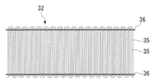
図1は、本発明の製造方法によって製造される中空糸膜モジュールの一例を示す断面図である。この中空糸膜モジュール30は、円筒状のケース31と、ケース31内に収納された、中空糸膜束32からなるロール33と、ロール33の端部をケース31内に固定する樹脂固定部34とから概略構成されるものである。ここで、ロール33は、複数の中空糸膜35をU字状に折り曲げ、折り曲げ部分を拘束糸条36によって結束した帯状の中空糸膜束32が、ストロー37を中心に巻き回された状態にあるものである。
【0015】
ケース31の材質としては、機械的強度および耐久性を有するものであればよく、例えばポリカーボネート、ポリスルフォン、ポリオレフィン、PVC(ポリ塩化ビニル)、アクリル樹脂、ABS樹脂、変成PPE(ポリフェニレンエーテル)等を用いることができる。
【0016】
中空糸膜35としては、種々のものが使用でき、例えばセルロース系、ポリオレフィン系、ポリビニルアルコール系、PMMA(ポリメタクリル酸メチル)系、ポリスルフォン系など、各種材科からなる中空糸膜が使用できる。中でも、ポリエチレン等の強伸度の高い材質からなる中空糸膜を用いることが好ましい。
なお、濾過膜として使用可能な中空糸膜であれば、その孔径、空孔率、膜厚、外径等は、特に限定されるものではないが、例えば、その外径は20〜2000μm、孔径は0.01〜1μm、空径率は20〜90%、膜厚は5〜300μmの範囲とされる。
【0017】
拘束糸条36は、図1に示されるように所定の位置でチェーンステッチ(鎖編み)により各中空糸膜35を結束するものである。拘束糸条36を構成する繊維の種類としては、ポリエステル繊維など耐水性を有する合成繊維製のマルチフィラメント糸や紡績糸を用いることができ、使用条件などにより適宜選択することが望ましい。糸条の最適な本数は、特に限定はされないが、例えば、2〜5本の範囲内とされる。
【0018】
この中空糸膜モジュール30は、以下のようにして製造される。
まず、図2に示すような、帯状の中空糸膜束32(編織物)を作製する。この中空糸膜束32は、いわゆるラッセル編みにより作製されるものであり、複数の中空糸膜35を、中空糸膜束32の幅の長さに複数回折り返し、この折り返し部分を、中空糸膜束32の長手方向に延びるチェーンステッチの拘束糸条36にて結束させたものである。
【0019】
次いで、この中空糸膜束32に気体を吹き付け、中空糸膜束32を解すことにより、各中空糸膜35を均一に分散させる(以下、この作業を開繊ともいう)。中空糸膜束32を開繊した後、これを、ストロー37を中心にして巻き回して図3に示すような中空糸膜束32からなるロール33とする。このロール33を、図4に示すように、底部に放射状に延びる複数の溝が形成された有底筒状のケース31に収納する。次いで、底部から樹脂注入管41が下方に延び、内部に液状の固定用樹脂42が充填された、有底円筒状の樹脂ポット40を、樹脂注入管41がストロー37に挿入されるようにして、ロール33上に配置する。
【0020】
次いで、ケース31内にロール33が収納され、ロール33上に樹脂ポット40が配置されたものを、遠心機(図示略)にセットし、遠心力によって樹脂ポット40中の固定用樹脂42を、ストロー37を通してケース31の底部に注入し、ケース31とロール33との間、そして各中空糸膜35間に流し込んで行き渡らせる。
固定用樹脂42を固化させて樹脂固定部34とした後、ロール33の底部側を、ケース31および樹脂固定部34ごと切断して、中空糸膜35の端部を開口させることにより、図1に示す中空糸膜モジュール30が製造される。
【0021】
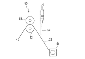
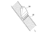
上述した中空糸膜束32の開繊は、具体的には、図5および図6に示すような開繊装置50を用いて行われる。この開繊装置50は、中空糸膜束32の先頭を一対のピンガイド(図示略)で把持しつつピンガイドを回転させて、ストロー37を中心にして中空糸膜束32を巻き取る巻取装置51(搬送手段)と、供給された中空糸膜束32を巻取装置51へと導くガイドローラ52と、ガイドローラ52との間で中空糸膜束32を挟み込む押さえローラ53と、気体を供給する気体供給手段(図示略)と、気体をコロナ放電によって処理する気体処理手段(図示略)と、巻取装置51へと搬送される中空糸膜束32に、コロナ放電によって処理された気体を吹き付けるノズル54(気体噴出手段)とから概略構成されるものである。
【0022】
気体処理手段としては、例えば、電極針に交流高電圧を印加して電極針にコロナ放電させ、電極針からプラスイオン、マイナスイオンを交互に発生させる除電器などが使用できる。気体供給手段としては、例えば、エアーコンプレッサなどが使用できる。
【0023】
ノズル54は、先端に複数の吹き出し口が、ノズルの幅方向に直線状に整列して設けられたフラットノズルであり、その幅方向が中空糸膜束32の幅方向と平行になるように設置されている。
ノズル54の吹き出し口の内径は0.1mm〜5mmの範囲であることが好ましく、より好ましくは、0.5mm〜2mmの範囲である。内径が0.1mm未満では、中空糸膜35の間隙を気体が通過してしまうために開繊効果は著しく低下するおそれがある。一方、内径が5mmを超えると、気体の圧力に関わらず、複数本の中空糸膜35に同時に気体が吹き付けられてしまうため、中空糸膜束32を開繊するには至らないおそれがある。前述の寸法範囲であれば中空糸膜35の間に気体が入り込み、従って極めて良好な開繊効果を発現することができる。
【0024】
ノズル54の位置は、その先端が中空糸膜束32に接触しない範囲で中空糸膜束32の近傍に配置されることが好ましく、ノズル54と中空糸膜束32との間の距離は、例えば、100mm以下とされ、好ましくは5〜50mmの範囲である。ノズル54の位置が中空糸膜束32から離れすぎると、ノズル54の吹き出し口の内径を前述の範囲としても、複数本の中空糸膜35に同時に気体が吹き付けられてしまい、中空糸膜束32を開繊するには至らないおそれがある。
【0025】
中空糸膜束32とノズル54との相対的な移動速度は、好ましくは1〜30m/minである。移動速度が1m/min未満では中空糸膜モジュールの生産性が著しく低下し、一方、30m/minを超えると、中空糸膜束32の開繊効果が低下する傾向となる。
中空糸膜束32に吹き付ける気体は、中空糸膜束32の平面に対して10〜80゜の角度で、かつ中空糸膜束32の搬送方向と同じ方向にノズル54より噴出させることが好ましい。中空糸膜束32に吹き付ける気体の角度が中空糸膜束32の平面に対して10゜未満では、気体が中空糸膜束32の外表面のみを通過してしまうために開繊効果が著しく低下するおそれがあり、一方、80゜を超えると、中空糸膜35の間隙を気体が通過してしまうために開繊効果は著しく低下するおそれがある。また、中空糸膜束32の搬送方向とは逆の方向にノズル54から気体を噴出させると、中空糸膜束32の搬送の妨げとなるおそれがある。
【0026】
中空糸膜束32に吹き付けられる気体の圧力は、中空糸膜束の表面において0.01〜0.5MPaの範囲であることが好ましく、より好ましくは、0.05〜0.2MPaの範囲である。気体の圧力が0.01MPa未満では、圧力が低すぎるため中空糸膜束32を開繊するには至らないおそれがある。一方、気体の圧力が0.5MPaを超えると、中空糸膜35が交絡するおそれが高くなるため好ましくない。前述の圧力範囲による気体供給によって、中空糸膜束32の良好な開繊効果が発現される。
【0027】
また、中空糸膜束32に吹き付けられる気体の流量は、0.1〜200L/minの範囲であることが好ましい。気体の流量が0.1L/min未満では、流量が少なすぎるため中空糸膜束32を開繊するには至らないおそれがある。一方、気体の流量が200L/minを超えると、中空糸膜35が交絡するおそれが高くなるため好ましくない。
【0028】
上述の固定用樹脂42としては、エポキシ樹脂、不飽和ポリエステル樹脂、ポリウレタン樹脂、シリコーン系充填材、各種ホットメルト樹脂等を用いることができ、適宜選定することが可能である。また、固化前の固定用樹脂42の粘度も、特に限定はされないが、500〜3000mPa・sが好ましい。固定用樹脂42の粘度が500mPa・s未満では、固定用樹脂42が中空糸膜35の外表面にて毛管現象による吸い上げが大きくなるおそれがある。固定用樹脂42の粘度が3000mPa・sを超えると、各中空糸膜35間に固定用樹脂42を行き渡らせることが困難となるので好ましくない。
【0029】
以上説明した中空糸膜モジュール30の製造方法にあっては、中空糸膜束32をロール33にしてケース31内に収納する前に、中空糸膜束32に気体を吹き付けているので、中空糸膜束32が開繊され、中空糸膜35が均一に分散される。これにより、固定用樹脂42が各中空糸膜35の間に行き渡り、固定用樹脂42を固化させた樹脂固定部34においてリークが発生することがない。また、製造された中空糸膜モジュール30を液体や気体の濾過処理に使用した場合、流体が中空糸膜35全体に均一に流れ、濾過性能を十分に発揮させることができる。
【0030】
また、中空糸膜束32に吹き付ける気体が、コロナ放電により処理されているので、この気体に含まれるプラスイオンまたはマイナスイオンによって中空糸膜35表面の静電気が中和され、中空糸膜35同士が交絡することがない。これにより、固定用樹脂42が各中空糸膜35の間にさらに行き渡り易くなる。また、製造された中空糸膜モジュール30を液体や気体の濾過処理に使用した場合、流体が中空糸膜35全体により均一に流れ、濾過性能を安定化させることができる。
【0031】
また、中空糸膜束32が、その幅の長さに折り返した中空糸膜35の折り返し部分を、中空糸膜束32の長手方向に延びる拘束糸条36にて結束させたものであるので、中空糸膜35を均一に整列させ、かつその状態を保持することができる。これにより、固定用樹脂42が各中空糸膜35の間にさらに行き渡り易くなる。また、製造された中空糸膜モジュール30を液体や気体の濾過処理に使用した場合、流体が中空糸膜35全体により均一に流れ、濾過性能をさらに安定化させることができる。
また、中空糸膜束32を巻回してロール33とし、このロール33をケース31内に収納しているので、中空糸膜35が均一にかつ高密度に整列された中空糸膜モジュール30を容易に製造することができる。
【0032】
なお、本発明の中空糸膜モジュールの製造方法は、図1に示す中空糸膜モジュール30の製造に限定されるものではなく、例えば、図10に示すような、中空糸膜束13の両端が樹脂固定部14にてケース11に固定された中空糸膜モジュール10の製造にも適用可能である。
【0033】
また、上述の開繊装置におけるノズルの形状は、図示例のような複数の吹き出し口を有するものに限定はされず、単管のノズルを用いても構わない。ただし、中空糸膜束32へ吹き付けられる気体の圧力および量は、中空糸膜束32表面全体において均一になることが好ましいことから、複数の吹き出し口を直線状に整列させたノズル、または複数の吹き出し口を円周状に配列させたノズルが好ましい。
また、ノズルの数も特に限定はされず、中空糸膜束32の搬送方向に図示したようなフラットノズルを複数配置しても構わない。
【0034】
ノズル54から噴出される気体の種類については、特に限定されるものではなく、中空糸膜35に対して悪影響を与えないものであれば適宜使用可能であるが、水分、ゴミ、油分が除去された気体が好ましい。
また、図示例では、搬送中の中空糸膜束32に対し、固定されたノズル54から空気を吹き付けているが、この形態には限定されず、中空糸膜束32またはノズル54のいずれか一方を移動させればよい。
また、開繊装置における搬送手段は、図示例の巻取装置51に限定はされず、単なる巻き取りローラなどを用いても構わない。
【0035】
(形態例2)
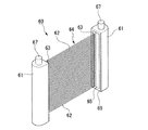
図7は、本発明の製造方法によって製造される中空糸膜モジュールの他の例を示す斜視図である。この中空糸膜モジュール60は、ハウジング61と、複数の中空糸膜62が拘束糸条63によってシート状に束ねられた中空糸膜束64と、中空糸膜束64の端部を、中空糸膜62端部の開口状態を保ったままハウジング61に固定する樹脂固定部65とから概略構成される。
【0036】
ハウジング61は、図8に示すように、内部に内部路66が形成された断面U字形の筒状体である。ハウジング61の少なくとも一端には、内部路66に連通し、外部に開口した配管67が設けられている。
また、ハウジング61の側面には、中空糸膜束64の端部を内部路66に収納するための挿入口となるスリット状の開口部68が形成され、この開口部68の周囲を囲むように、液状の固定用樹脂の垂れ防止のための堰69がハウジング61と一体になって形成されている。そして、この堰69に囲まれた部分が、固定用樹脂を注入するための樹脂注入部70となっている。
【0037】
ハウジング61の材質としては、機械的強度および耐久性を有するものであればよく、例えばポリカーボネート、ポリスルフォン、ポリオレフィン、PVC(ポリ塩化ビニル)、アクリル樹脂、ABS樹脂、変成PPE(ポリフェニレンエーテル)等を用いることができる。
中空糸膜62としては、上述の中空糸膜35と同じものを用いることができる。
拘束糸条63は、所定の位置でチェーンステッチにより各中空糸膜62を結束するものである。拘束糸条63を構成する繊維としては、上述の拘束糸条36と同じものを用いることができる。
【0038】
中空糸膜束64としては、中空糸膜62を単にひき揃えたものでもよいが、中空糸膜64を緯糸として用いて編み地としたもの、すなわち図2に示すようなラッセル編みの中空糸膜束、またはこの編み地を数枚積層して積層体としたものが、中空糸膜モジュール60の加工性の面から好適である。
ここでいう編み地を複数枚積層した中空糸膜束には、編み地を切断せずに適当な長さに折り畳み重ねたものも包含される。編み地の積層(折り畳み)枚数は、編み地の厚さ、すなわち中空糸膜62の太さや編み地を編成する際の中空糸膜62の合糸本数によっても変化するが、通常は5枚程度までがよい。
【0039】
次に、中空糸膜モジュール60の製造方法について説明する。
まず、複数の中空糸膜62を拘束糸条63によってシート状に束ねて、中空糸膜束64を作製する。この際、拘束糸条63は、中空糸膜束64をハウジング61の開口部68に挿入した際、開口部68の開口端部から開口部68外方2〜20mmに位置するように、かつ開口部68に対して略平行になるように、中空糸膜束64に設けられる。また、中空糸膜束64を構成している各中空糸膜62の端部をあらかじめカットして開口させておく。
【0040】
次いで、中空糸膜束64の端部を、ハウジング61の開口部68から中空糸膜62の開口端部がハウジング61の内部路66に位置するように挿入する。
中空糸膜束64の端部をハウジング61内に収納した後、図9に示すように、ハウジング61の開口部68付近の樹脂注入部70の中空糸膜62に、コンプレッサー等に接続されたノズル71から気体を吹き付け、中空糸膜束64を解すことにより、各中空糸膜62を均一に分散させる(以下、この作業を開繊ともいう)。気体の吹き付けは、ノズル71をハウジング61の開口部68のスリット長手方向に移動させながら行い、中空糸膜束64のすべての中空糸膜62に気体を吹き付ける。
【0041】
次いで、中空糸膜62の端部の開口状態を保ったまま、液状の固定用樹脂をハウジング61の外側から樹脂注入部70および開口部68に充填し、これを固化させて樹脂固定部65とし、中空糸膜束64をハウジング61に固定することにより、図7に示す中空糸膜モジュール60が製造される。
【0042】
中空糸膜束64の端部の開繊に使用されるノズル71は、中空の円筒形状のものであり、噴出する気体が広範囲に散乱しないように先端が細くされた先端構造であることが好ましい。また、その材質には限定はない。
ノズル71の寸法は、後述する気体の圧力により適宜決定することが可能である。
【0043】
ノズル71の吹き出し口の内径は0.1mm〜5mmの範囲であることが好ましく、より好ましくは、0.5mm〜2mmの範囲である。内径が0.1mm未満では、中空糸膜62の間隙を気体が通過してしまうために開繊効果は著しく低下するおそれがある。一方、内径が5mmを超えると、気体の圧力に関わらず、複数本の中空糸膜62に同時に気体が吹き付けられてしまうため、各々の中空糸膜束64を開繊するには至らないおそれがある。前述の寸法範囲であれば中空糸膜62の間に気体が入り込み、従って極めて良好な開繊効果を発現することができる。
【0044】
ノズル71の位置は、その先端が中空糸膜束64に接触しない範囲で中空糸膜束64の近傍に配置されることが好ましく、ノズル71と中空糸膜束64との間の距離は、例えば、5mm以下とされ、好ましくは0.1〜2.0mmの範囲である。ノズル71の位置が中空糸膜束64から離れすぎると、ノズル71の内径を前述の範囲としても、複数本の中空糸膜62に同時に気体が吹き付けられてしまい、中空糸膜束64を開繊するには至らないおそれがある。
【0045】
ノズル71の移動速度は、好ましくは0.1〜5.0m/minであり、より好ましくは0.5〜2.0m/minである。ノズル71の移動速度が0.1m/min未満では中空糸膜モジュールの生産性が著しく低下し、一方、5.0m/minを超えると、中空糸膜束64の開繊効果が低下する傾向となる。
【0046】
ノズル71から供給される気体は、気体処理手段(図示略)においてコロナ放電により処理された気体である。気体処理手段としては、例えば、電極針に交流高電圧を印加して電極針にコロナ放電させ、電極針からプラスイオン、マイナスイオンを交互に発生させる除電器などが使用できる
気体の種類は、特に限定されるものではなく、中空糸膜62に対して悪影響を与えぬものであれば適宜使用可能であるが、水分、ゴミ、油分が除去された気体が好ましい。
コンプレッサー等からノズル71に送られる気体の圧力は、前述のノズルの配置位置や直径によって適宜決定することが好ましい。
【0047】
中空糸膜束64に吹き付けられる気体の圧力は、中空糸膜束の表面において0.01〜0.5MPaの範囲であることが好ましく、より好ましくは、0.2〜0.4MPaの範囲である。気体の圧力が0.01MPa未満では、圧力が低すぎるため中空糸膜束64を開繊するには至らないおそれがある。一方、気体の圧力が0.5MPaを超えると、中空糸膜62が気体圧力により押し倒されることによる折れ曲がりの危険性が高くなるため好ましくない。前述の圧力範囲による気体供給によって、中空糸膜束64の良好な開繊効果が発現される。
【0048】
また、中空糸膜束64に吹き付けられる気体の流量は、0.1〜350L/minの範囲であることが好ましく、より好ましくは、10〜125L/minの範囲であり、さらに好ましくは、10〜40L/minの範囲である。気体の流量が0.1L/min未満では、流量が少なすぎるため中空糸膜束64を開繊するには至らないおそれがある。一方、気体の流量が350L/minを超えると、中空糸膜62が気体により押し倒されることによる折れ曲がりの危険性が高くなるため好ましくない。
【0049】
拘束糸条63は、中空糸膜62を解れやすくし、極めて良好な開繊効果を発現させるためのものである。また、拘束糸条63は、樹脂注入部70へ注入した液状の固定用樹脂の這い上がりを堰き止める効果を有し、かつ、固定用樹脂の這い上がりによる硬化部と中空糸膜62との界面を柔軟構造状に把持することにより、応力を分散吸収し、中空糸膜62の損傷を抑制する効果を有する。
【0050】
固定用樹脂としては、エポキシ樹脂、不飽和ポリエステル樹脂、ポリウレタン樹脂、シリコーン系充填材、各種ホットメルト樹脂等を用いることができ、適宜選定することが可能である。また、固化前の固定用樹脂の粘度も、特に限定はされないが、500〜5000mPa・sが好ましく、より好ましくは2000〜3000mPa・sの範囲である。固定用樹脂の粘度が500mPa・s未満では、固定用樹脂が中空糸膜62の開口端部まで流動し、該開口端部を閉塞する原因となるおそれがある。固定用樹脂の粘度が5000mPa・sを超えると、中空糸膜62間に含浸することが困難となるので好ましくない。
【0051】
以上説明した中空糸膜モジュール60の製造方法にあっては、中空糸膜束64に吹き付ける気体が、コロナ放電により処理されているので、この気体に含まれるプラスイオンまたはマイナスイオンによって中空糸膜62表面の静電気が中和され、中空糸膜62同士が交絡することがなく、中空糸膜62が均一に分散される。これにより、固定用樹脂が各中空糸膜62の間に行き渡り、固定用樹脂を固化させた樹脂固定部65においてリークが発生することがない。
【0052】
なお、図示例の中空糸膜モジュール60の製造方法では、あらかじめ中空糸膜62の端部をカットして開口し、中空糸膜62の端部の開口状態を保ったまま固定用樹脂を注入しているが、本発明の中空糸膜モジュールの製造方法はこれに限定されるものではない。例えば、中空糸膜62の端部をあらかじめカットしていない中空糸膜束64の端部をハウジング61内に挿入し、ハウジング61の樹脂注入部70近傍の中空糸膜束64に気体を吹き付けた後、中空糸膜62の端部をすべて覆うようにハウジング61の内部路66まで固定用樹脂を注入し、これが固化した後、内部路66内の樹脂固定部を中空糸膜62の端部と一緒にカットし、中空糸膜62端部を開口させる方法などが挙げられる。
【0053】
【実施例】
以下、本発明を実施例を示して詳しく説明する。
(実施例1)
図1に示すような、中空糸膜モジュールを以下のようにして製造した。
まず、三菱レイヨン(株)製のポリエチレン製中空糸膜(分画性能0.1μm、外径380μm)を5000本まとめた糸束を、65mmの長さで折り返しながら、その両側の折り返し部分を、ポリエステルフィラメント糸を用いたチェーンステッチにて結束させ、帯状の中空糸膜束とした。
【0054】
この中空糸膜束を、図5に示すような開繊装置内において5m/minの速度で搬送しながら、中空糸膜束の表面から先端が10mmの距離となり、中空糸膜束の平面に対して30゜の角度となるように設置されたノズルから、気体処理手段にてコロナ放電により処理された空気を、中空糸膜束の表面における圧力が0.1MPaとなるように、中空糸膜束表面に吹き付けた。ここで、ノズルとしては、内径0.8mmの吹き出し口を16個、3mm間隔で直線状に整列させたアルミニウム製のフラットノズル(スプレーイングシステムズジャパン(株)製)を用いた。また、気体処理手段としては、1本の電極針に交流高電圧(±0.7kV)を印加して電極針にコロナ放電させ、電極針からプラスイオン、マイナスイオンを交互に発生させる方式の除電器((株)キーエンス製、スポットタイプ除電器)を用いた。
【0055】
開繊後の中空糸膜束は、中空糸膜同士が交絡せず、各中空糸膜が離間するような状態でほぼ均一に分散されていた。また、中空糸膜束の平均帯電量を静電気センサ((株)キーエンス製)を用いて測定したところ、−0.2〜0kVであり、中空糸膜束表面は電気的にほぼ中和され、静電気はほぼ除去されていた。
次いで、この中空糸膜束を、中心にストローを配置した状態で巻取装置にて巻き取り、直径約38mmの中空糸膜束のロールを作製した。このロールを、中空糸膜束の側部がケースの底部に位置するように、有底円筒状のケース内に収納した。ここで、有底円筒状のケースとしては、内径40mm、高さ70mm、筒部の肉厚2mmのABS樹脂製の成形品を用いた。
【0056】
次いで、液状の固定用樹脂を、ストローを通して遠心力にてケースの底部に注入し、各中空糸膜間、およびロールとケースとの間に流し込み、行き渡らせた。ここで、固定用樹脂としては、粘度1500mPa・sのポリウレタン樹脂を用いた。
固定用樹脂を固化させた後、ケースの底部側端部から10mmの位置でケースの軸に直交して中空糸膜束をケースおよび樹脂固定部ごと切断し、中空糸膜の端部を開口させた。
このようにして得られた中空糸膜モジュールにおいては、固定用樹脂の充填不良による樹脂固定部におけるリークの発生はなかった。また、中空糸膜は、それら間に適度な隙間が形成された状態でケースに固定されており、中空糸膜モジュールは、良好な濾過性能を示した。
【0057】
(比較例1)
中空糸膜束に気体を吹き付けない以外は、実施例1と同様にして中空糸膜モジュールを得た。
得られた中空糸膜モジュール200本のうち3本に、樹脂固定部におけるリークが発生した。これらリーク品の樹脂固定部の切断面を観察したところ、中空糸膜の分布に粗密が生じており、密の部分における、中空糸膜同士が強く接触している部分においてリークが発生していることが特定された。
また、リークが発生していない中空糸膜モジュールについて、濾過試験を行ったところ、100本のうち1本に、比較的早期に濾過性能に不具合が生じた。
【0058】
【発明の効果】
以上説明したように、本発明の中空糸膜モジュールの製造方法は、中空糸膜を集束した中空糸膜束をケース内に収納し、中空糸膜束を固定用樹脂によってケース内に固定する中空糸膜モジュールの製造方法において、中空糸膜束をケース内に収納する前に、中空糸膜束に気体を吹き付ける方法であるので、中空糸膜の偏りが少なく、樹脂固定部においてリークが発生することがない中空糸膜モジュールを得ることができる。
【0059】
また、本発明の中空糸膜モジュールの製造方法において、前記中空糸膜束が、帯状の編織物であり、該編織物が、編織物の幅の長さに折り返した中空糸膜の折り返し部分を、編織物の長手方向に延びる拘束糸条にて結束させたものであれば、中空糸膜を均一に整列させ、かつその状態を保持することができる。
また、本発明の中空糸膜モジュールの製造方法において、前記編織物に気体を吹き付けた後にこれを巻回してロールとし、このロールを有底円筒状のケース内に収納するようにすれば、中空糸膜が均一にかつ高密度に整列された中空糸膜モジュールを容易に製造することができる。
また、中空糸膜束に吹き付ける気体が、コロナ放電により処理された気体であれば、中空糸膜の偏りをさらに少なくすることができる。
【0060】
また、本発明の中空糸膜モジュールの製造方法は、中空糸膜を収束した中空糸膜束の端部をハウジングの開口部からハウジング内に挿入し、開口部付近の中空糸膜束を固定用樹脂によってハウジングに固定する中空糸膜モジュールの製造方法において、ハウジングに中空糸膜束を固定用樹脂によって固定する前に、ハウジングの開口部付近の中空糸膜束に、コロナ放電により処理された気体を吹き付ける方法であるので、樹脂固定部においてリークが発生することがない中空糸膜モジュールを得ることができる。
【0061】
また、本発明の中空糸膜束の開繊装置は、中空糸膜を収束した中空糸膜束を搬送する搬送手段と、気体をコロナ放電により処理する気体処理手段と、搬送中の中空糸膜束に、コロナ放電により処理された気体を吹き付ける気体噴出手段とを具備するものであるので、容易に、中空糸膜束を開繊して、中空糸膜の偏りをなくすことができる。
【図面の簡単な説明】
【図1】本発明の製造方法によって得られる中空糸膜モジュールの一例を示す断面図である。
【図2】中空糸膜束の一例を示す正面図である。
【図3】図2の中空糸膜束を巻き回したロール体である。
【図4】中空糸膜モジュールの製造の一工程を示す断面図である。
【図5】本発明の中空糸膜束の開繊装置の一例を示す概略図である。
【図6】中空糸膜束にノズルから気体を吹き付ける様子を示す斜視図である。
【図7】本発明の製造方法によって得られる中空糸膜モジュールの他の例を示す断面図である。
【図8】図7の中空糸膜モジュールのハウジング部分の断面図である。
【図9】中空糸膜束にノズルから気体を吹き付ける様子を示す断面図である。
【図10】中空糸膜モジュールの一例を示す断面図である。
【図11】中空糸膜モジュールの他の例を示す断面図である。
【符号の説明】
30 中空糸膜モジュール
31 ケース
32 中空糸膜束
33 ロール
34 樹脂固定部(固定用樹脂)
35 中空糸膜
36 拘束糸条
42 固定用樹脂
51 巻取装置(搬送手段)
54 ノズル(気体噴出手段)
60 中空糸膜モジュール
61 ハウジング
62 中空糸膜
64 中空糸膜束
65 樹脂固定部(固定用樹脂)
68 開口部[0001]
TECHNICAL FIELD OF THE INVENTION
The present invention relates to a method for manufacturing a hollow fiber membrane module and a method for opening a hollow fiber membrane bundle.
[0002]
[Prior art]
2. Description of the Related Art Conventionally, hollow fiber membrane modules have been used in many applications such as production of aseptic water, drinking water, highly pure water, and purification of air.
As the hollow fiber membrane module, as shown in FIG. 10, a
[0003]
In such a hollow fiber membrane module, a hollow
In this hollow fiber membrane module, for example, in the case of a filtration treatment of water, the raw water side and the purified water side are separated so that raw water before passing through the
[0004]
JP-B-56-53405 and JP-B-2-37791 disclose that a hollow resin membrane is dispersed by spraying a gas onto an end of a hollow fiber membrane bundle housed in a case and then filled with a fixing resin. A method for doing so is disclosed.
However, the hollow fiber membrane bundle accommodated in the case is regulated by the case, and the gas blown to the end of the hollow fiber membrane bundle does not blow out from the outside to the inside of the case, and the hollow fiber membrane It only hits the end face of the membrane bundle.
[0005]
Therefore, the hollow fiber membrane at the end of the hollow fiber membrane bundle is hard to disperse, and partial bias tends to occur. Then, it becomes difficult for the fixing resin to flow into the portion where the hollow fiber membrane is dense, and a so-called leak state occurs in which the unfixed portion of the fixing resin causes insufficient partitioning by the resin fixing portion. It was frequent.
Further, the hollow fiber membrane inside the case to which the blown gas does not hit is not dispersed and has a large bias. Therefore, when the hollow fiber membrane module is used for filtering liquid or gas, the fluid does not flow uniformly throughout the hollow fiber membrane, and the filtration performance cannot be sufficiently exerted.
[0006]
In recent years, in addition to the above applications, hollow fiber membrane modules have been used in secondary and tertiary treatments in sewage treatment plants, solid-liquid separation in septic tanks, solid-liquid separation of SS (suspended substances) in industrial wastewater, etc. It is used for the treatment of highly polluted water.
As such a hollow fiber membrane module, as shown in FIG. 11, a hollow
[0007]
In such a hollow
Also in this hollow fiber membrane module, since it is necessary to partition the inside and the outside of the
[0008]
JP-A-2001-54724 discloses that before a hollow fiber membrane bundle is fixed to a housing by a fixing resin, a gas is blown onto the hollow fiber membrane bundle near an opening of the housing to disperse the hollow fiber membrane. A method of filling a fixing resin is disclosed.
However, simply blowing gas to the end of the hollow fiber membrane bundle may cause entanglement between the hollow fiber membranes, resulting in unevenness at the end of the hollow fiber membrane bundle. Therefore, it becomes difficult for the fixing resin to flow into the portion where the hollow fiber membrane is dense, and a leak state rarely occurs due to the unimpregnated portion of the fixing resin.
[0009]
[Patent Document 1]
JP-B-56-53405 (page 3-5, FIG. 7)
[Patent Document 2]
Japanese Patent Publication No. 2-37791 (Pages 2-4, Fig. 1)
[Patent Document 3]
JP 2001-226496 A (page 3-7, FIG. 3)
[0010]
[Problems to be solved by the invention]
Accordingly, an object of the present invention is to provide a method for manufacturing a hollow fiber membrane module in which the hollow fiber membrane is less biased and no leak occurs in the resin fixing portion, and a hollow fiber membrane bundle is opened to form a hollow fiber membrane. An object of the present invention is to provide an apparatus for opening a hollow fiber membrane bundle that eliminates bias.
[0011]
[Means for Solving the Problems]
That is, the method for producing a hollow fiber membrane module of the present invention is directed to a hollow fiber membrane module in which a hollow fiber membrane bundle in which hollow fiber membranes are bundled is housed in a case, and the hollow fiber membrane bundle is fixed in the case by a fixing resin. In the manufacturing method, a gas is blown to the hollow fiber membrane bundle before the hollow fiber membrane bundle is stored in the case.
[0012]
In the method for manufacturing a hollow fiber membrane module according to the present invention, the hollow fiber membrane bundle is a belt-shaped knitted fabric, and the knitted fabric is a folded portion of the hollow fiber membrane folded to the width of the knitted fabric. Are bound by a restraining thread extending in the longitudinal direction of the knitted fabric.
In the method for producing a hollow fiber membrane module of the present invention, it is preferable that a gas is blown onto the knitted fabric and then wound to form a roll, and the roll is housed in a bottomed cylindrical case.
The gas blown to the hollow fiber membrane bundle is preferably a gas treated by corona discharge.
[0013]
Further, the method for producing a hollow fiber membrane module of the present invention includes the steps of: inserting an end of the hollow fiber membrane bundle in which the hollow fiber membranes are converged into the housing from the opening of the housing; and fixing the hollow fiber membrane bundle near the opening. In the method for manufacturing a hollow fiber membrane module to be fixed to a housing by a resin, before the hollow fiber membrane bundle is fixed to the housing by the fixing resin, the hollow fiber membrane bundle near the opening of the housing is treated with a gas treated by corona discharge. Is sprayed.
In addition, the hollow fiber membrane bundle opening apparatus of the present invention includes a conveying unit that conveys the hollow fiber membrane bundle converging the hollow fiber membrane, a gas processing unit that processes gas by corona discharge, and a hollow fiber membrane that is being conveyed. The bundle is provided with gas jetting means for blowing gas treated by corona discharge.
[0014]
BEST MODE FOR CARRYING OUT THE INVENTION
Hereinafter, the present invention will be described in detail.
(Form example 1)
FIG. 1 is a sectional view showing an example of a hollow fiber membrane module manufactured by the manufacturing method of the present invention. The hollow
[0015]
The material of the
[0016]
As the
In addition, as long as it is a hollow fiber membrane that can be used as a filtration membrane, its pore size, porosity, film thickness, outer diameter, and the like are not particularly limited. For example, the outer diameter is 20 to 2000 μm, Is 0.01 to 1 μm, the porosity is 20 to 90%, and the film thickness is 5 to 300 μm.
[0017]
As shown in FIG. 1, the restraining
[0018]
This hollow
First, a band-shaped hollow fiber membrane bundle 32 (knitted fabric) as shown in FIG. 2 is prepared. The hollow
[0019]
Next, a gas is blown onto the hollow
[0020]
Next, the case where the
After the fixing
[0021]
The opening of the hollow
[0022]
As the gas treatment means, for example, a static eliminator that applies a high alternating voltage to the electrode needle to cause corona discharge to the electrode needle, and alternately generates positive ions and negative ions from the electrode needle can be used. As the gas supply means, for example, an air compressor can be used.
[0023]
The
The inner diameter of the outlet of the
[0024]
The position of the
[0025]
The relative moving speed between the hollow
The gas blown to the hollow
[0026]
The pressure of the gas blown to the hollow
[0027]
The flow rate of the gas blown to the hollow
[0028]
As the fixing
[0029]
In the method of manufacturing the hollow
[0030]
Further, since the gas blown to the hollow
[0031]
Further, since the hollow
Further, since the hollow
[0032]
In addition, the manufacturing method of the hollow fiber membrane module of the present invention is not limited to the manufacturing of the hollow
[0033]
In addition, the shape of the nozzle in the above-described fiber opening device is not limited to one having a plurality of outlets as in the illustrated example, and a single tube nozzle may be used. However, since the pressure and amount of gas blown to the hollow
In addition, the number of nozzles is not particularly limited, and a plurality of flat nozzles as shown in the figure may be arranged in the transport direction of the hollow
[0034]
The type of gas ejected from the
Further, in the illustrated example, air is blown from the fixed
Further, the conveying means in the fiber opening device is not limited to the winding
[0035]
(Form example 2)
FIG. 7 is a perspective view showing another example of the hollow fiber membrane module manufactured by the manufacturing method of the present invention. The hollow
[0036]
As shown in FIG. 8, the
In addition, a slit-shaped
[0037]
The material of the
As the
The restraining
[0038]
The hollow
The hollow fiber membrane bundle formed by laminating a plurality of knitted fabrics as described herein includes a fabric obtained by folding and knitting a knitted fabric to an appropriate length without cutting the knitted fabric. The number of knitted fabrics to be laminated (folded) varies depending on the thickness of the knitted fabric, that is, the thickness of the
[0039]
Next, a method for manufacturing the hollow
First, a plurality of
[0040]
Next, the end of the hollow
After the end of the hollow
[0041]
Next, while the open state of the end of the
[0042]
The
The size of the
[0043]
The inner diameter of the outlet of the
[0044]
The position of the
[0045]
The moving speed of the
[0046]
The gas supplied from the
The type of gas is not particularly limited, and any gas can be used as long as it does not adversely affect the
It is preferable that the pressure of the gas sent from the compressor or the like to the
[0047]
The pressure of the gas blown to the hollow
[0048]
The flow rate of the gas blown to the hollow
[0049]
The restraining
[0050]
As the fixing resin, an epoxy resin, an unsaturated polyester resin, a polyurethane resin, a silicone-based filler, various hot melt resins, and the like can be used, and can be appropriately selected. The viscosity of the fixing resin before solidification is not particularly limited, but is preferably 500 to 5000 mPa · s, and more preferably 2000 to 3000 mPa · s. If the viscosity of the fixing resin is less than 500 mPa · s, the fixing resin may flow to the open end of the
[0051]
In the manufacturing method of the hollow
[0052]
In the manufacturing method of the illustrated hollow
[0053]
【Example】
Hereinafter, the present invention will be described in detail with reference to examples.
(Example 1)
A hollow fiber membrane module as shown in FIG. 1 was manufactured as follows.
First, while folding a bundle of 5,000 polyethylene hollow fiber membranes (fractionation performance: 0.1 μm, outer diameter: 380 μm) manufactured by Mitsubishi Rayon Co., Ltd. at a length of 65 mm, the folded portions on both sides were folded. The bundle was tied by a chain stitch using polyester filament yarn to form a band-like hollow fiber membrane bundle.
[0054]
While the hollow fiber membrane bundle is being conveyed at a speed of 5 m / min in a fiber opening device as shown in FIG. 5, the tip is at a distance of 10 mm from the surface of the hollow fiber membrane bundle, Air treated by corona discharge with gas treatment means from a nozzle installed at an angle of 30 ° to the hollow fiber membrane bundle so that the pressure on the surface of the hollow fiber membrane bundle becomes 0.1 MPa. Sprayed on the surface. Here, as the nozzle, an aluminum flat nozzle (manufactured by Spraying Systems Japan Co., Ltd.) in which 16 air outlets having an inner diameter of 0.8 mm were linearly arranged at intervals of 3 mm was used. In addition, as a gas processing means, a method of applying a high alternating voltage (± 0.7 kV) to one electrode needle to cause a corona discharge to the electrode needle and alternately generating positive ions and negative ions from the electrode needle is used. An electric device (a spot type static eliminator manufactured by KEYENCE CORPORATION) was used.
[0055]
The hollow fiber membrane bundle after opening was almost uniformly dispersed in such a state that the hollow fiber membranes were not entangled and the hollow fiber membranes were separated. When the average charge amount of the hollow fiber membrane bundle was measured using an electrostatic sensor (manufactured by Keyence Corporation), it was -0.2 to 0 kV, and the surface of the hollow fiber membrane bundle was almost neutralized electrically. Static electricity was almost eliminated.
Next, the hollow fiber membrane bundle was wound up with a winding device in a state where a straw was arranged at the center, to produce a roll of a hollow fiber membrane bundle having a diameter of about 38 mm. The roll was housed in a bottomed cylindrical case so that the side of the hollow fiber membrane bundle was located at the bottom of the case. Here, as the bottomed cylindrical case, an ABS resin molded product having an inner diameter of 40 mm, a height of 70 mm, and a wall thickness of 2 mm was used.
[0056]
Next, the liquid fixing resin was injected into the bottom of the case with a centrifugal force through a straw, and was poured between the hollow fiber membranes and between the roll and the case to be spread. Here, a polyurethane resin having a viscosity of 1500 mPa · s was used as the fixing resin.
After the fixing resin is solidified, the hollow fiber membrane bundle is cut together with the case and the resin fixing portion perpendicularly to the axis of the case at a
In the hollow fiber membrane module thus obtained, no leakage occurred in the resin fixing portion due to the improper filling of the fixing resin. Moreover, the hollow fiber membrane was fixed to the case in a state where an appropriate gap was formed between them, and the hollow fiber membrane module showed good filtration performance.
[0057]
(Comparative Example 1)
A hollow fiber membrane module was obtained in the same manner as in Example 1, except that no gas was blown onto the hollow fiber membrane bundle.
Three out of 200 obtained hollow fiber membrane modules leaked in the resin fixing portion. Observation of the cut surface of the resin fixing portion of these leaked products revealed that the distribution of the hollow fiber membranes was coarse and dense, and a leak occurred in the dense part where the hollow fiber membranes were in strong contact with each other. It was identified.
In addition, when a filtration test was performed on a hollow fiber membrane module in which no leak occurred, one out of 100 modules had a relatively early failure in filtration performance.
[0058]
【The invention's effect】
As described above, the method for manufacturing a hollow fiber membrane module of the present invention includes a hollow fiber membrane bundle in which hollow fiber membranes are bundled and housed in a case, and the hollow fiber membrane bundle is fixed in the case by a fixing resin. In the method for manufacturing a fiber membrane module, a gas is blown to the hollow fiber membrane bundle before the hollow fiber membrane bundle is housed in the case. Therefore, the bias of the hollow fiber membrane is small, and a leak occurs in the resin fixing portion. It is possible to obtain a hollow fiber membrane module without any problem.
[0059]
Further, in the method for producing a hollow fiber membrane module of the present invention, the hollow fiber membrane bundle is a belt-shaped knitted fabric, and the knitted fabric has a folded portion of the hollow fiber membrane folded back to the width of the knitted fabric. If the knitted and woven fabrics are bound by restraining yarns extending in the longitudinal direction, the hollow fiber membranes can be uniformly aligned and maintained in that state.
Further, in the method for producing a hollow fiber membrane module of the present invention, a gas is blown onto the knitted fabric and then wound into a roll, and if the roll is housed in a bottomed cylindrical case, hollow A hollow fiber membrane module in which fiber membranes are uniformly and densely arranged can be easily manufactured.
Further, if the gas blown to the hollow fiber membrane bundle is a gas treated by corona discharge, the bias of the hollow fiber membrane can be further reduced.
[0060]
Further, the method for producing a hollow fiber membrane module of the present invention includes the steps of: inserting an end of the hollow fiber membrane bundle in which the hollow fiber membranes are converged into the housing from the opening of the housing; and fixing the hollow fiber membrane bundle near the opening. In the method for manufacturing a hollow fiber membrane module to be fixed to a housing by a resin, before the hollow fiber membrane bundle is fixed to the housing by the fixing resin, the hollow fiber membrane bundle near the opening of the housing is treated with a gas treated by corona discharge. Is sprayed, it is possible to obtain a hollow fiber membrane module in which no leak occurs in the resin fixing portion.
[0061]
In addition, the hollow fiber membrane bundle opening apparatus of the present invention includes a conveying unit that conveys the hollow fiber membrane bundle converging the hollow fiber membrane, a gas processing unit that processes gas by corona discharge, and a hollow fiber membrane that is being conveyed. Since the bundle is provided with gas ejection means for blowing gas treated by corona discharge, the bundle of hollow fiber membranes can be easily opened to eliminate the bias of the hollow fiber membrane.
[Brief description of the drawings]
FIG. 1 is a cross-sectional view showing one example of a hollow fiber membrane module obtained by a production method of the present invention.
FIG. 2 is a front view showing an example of a hollow fiber membrane bundle.
FIG. 3 is a roll obtained by winding the hollow fiber membrane bundle of FIG. 2;
FIG. 4 is a cross-sectional view showing one process of manufacturing the hollow fiber membrane module.
FIG. 5 is a schematic view showing an example of the hollow fiber membrane bundle opening apparatus of the present invention.
FIG. 6 is a perspective view showing a state in which gas is blown from a nozzle to a hollow fiber membrane bundle.
FIG. 7 is a cross-sectional view showing another example of the hollow fiber membrane module obtained by the production method of the present invention.
8 is a sectional view of a housing part of the hollow fiber membrane module of FIG.
FIG. 9 is a cross-sectional view showing how a gas is blown from a nozzle to a hollow fiber membrane bundle.
FIG. 10 is a cross-sectional view illustrating an example of a hollow fiber membrane module.
FIG. 11 is a sectional view showing another example of the hollow fiber membrane module.
[Explanation of symbols]
30 Hollow fiber membrane module
31 cases
32 Hollow fiber membrane bundle
33 rolls
34 resin fixing part (resin for fixing)
35 hollow fiber membrane
36 Restraining yarn
42 Fixing resin
51 Winding device (transportation means)
54 nozzles (gas blowing means)
60 Hollow fiber membrane module
61 Housing
62 hollow fiber membrane
64 hollow fiber membrane bundle
65 Resin fixing part (resin for fixing)
68 opening
Claims (6)
中空糸膜束をケース内に収納する前に、中空糸膜束に気体を吹き付けることを特徴とする中空糸膜モジュールの製造方法。In a method for manufacturing a hollow fiber membrane module in which a hollow fiber membrane bundle in which a hollow fiber membrane is bundled is housed in a case and the hollow fiber membrane bundle is fixed in the case by a fixing resin,
A method for manufacturing a hollow fiber membrane module, comprising blowing a gas onto the hollow fiber membrane bundle before storing the hollow fiber membrane bundle in the case.
該編織物は、編織物の幅の長さに折り返した中空糸膜の折り返し部分を、編織物の長手方向に延びる拘束糸条にて結束させたものであることを特徴とする請求項1記載の中空糸膜モジュールの製造方法。The hollow fiber membrane bundle is a belt-shaped knitted fabric,
2. The knitted fabric according to claim 1, wherein the folded portion of the hollow fiber membrane folded to the width of the knitted fabric is bound by a restraining thread extending in the longitudinal direction of the knitted fabric. The method for producing a hollow fiber membrane module of the present invention.
ハウジングに中空糸膜束を固定用樹脂によって固定する前に、ハウジングの開口部付近の中空糸膜束に、コロナ放電により処理された気体を吹き付けることを特徴とする中空糸膜モジュールの製造方法。In a method for manufacturing a hollow fiber membrane module, an end of a hollow fiber membrane bundle in which a hollow fiber membrane is converged is inserted into the housing from an opening of the housing, and the hollow fiber membrane bundle near the opening is fixed to the housing by a fixing resin. ,
A method of manufacturing a hollow fiber membrane module, comprising blowing a gas treated by corona discharge onto a hollow fiber membrane bundle near an opening of a housing before fixing the hollow fiber membrane bundle to a housing with a fixing resin.
気体をコロナ放電により処理する気体処理手段と、
搬送中の中空糸膜束に、コロナ放電により処理された気体を吹き付ける気体噴出手段とを具備することを特徴とする中空糸膜束の開繊装置。Conveying means for conveying the hollow fiber membrane bundle converging the hollow fiber membrane,
Gas processing means for processing the gas by corona discharge,
A fiber opening device for a hollow fiber membrane bundle, comprising: gas blowing means for blowing a gas treated by corona discharge onto a hollow fiber membrane bundle being conveyed.
Priority Applications (1)
| Application Number | Priority Date | Filing Date | Title |
|---|---|---|---|
| JP2002375707A JP4338393B2 (en) | 2002-12-26 | 2002-12-26 | Method for producing hollow fiber membrane module |
Applications Claiming Priority (1)
| Application Number | Priority Date | Filing Date | Title |
|---|---|---|---|
| JP2002375707A JP4338393B2 (en) | 2002-12-26 | 2002-12-26 | Method for producing hollow fiber membrane module |
Related Child Applications (1)
| Application Number | Title | Priority Date | Filing Date |
|---|---|---|---|
| JP2007321783A Division JP4338756B2 (en) | 2007-12-13 | 2007-12-13 | Hollow fiber membrane module manufacturing method and hollow fiber membrane bundle opening device |
Publications (2)
| Publication Number | Publication Date |
|---|---|
| JP2004202402A true JP2004202402A (en) | 2004-07-22 |
| JP4338393B2 JP4338393B2 (en) | 2009-10-07 |
Family
ID=32813350
Family Applications (1)
| Application Number | Title | Priority Date | Filing Date |
|---|---|---|---|
| JP2002375707A Expired - Fee Related JP4338393B2 (en) | 2002-12-26 | 2002-12-26 | Method for producing hollow fiber membrane module |
Country Status (1)
| Country | Link |
|---|---|
| JP (1) | JP4338393B2 (en) |
Cited By (2)
| Publication number | Priority date | Publication date | Assignee | Title |
|---|---|---|---|---|
| CN103239996A (en) * | 2012-02-03 | 2013-08-14 | 三菱丽阳可菱水株式会社 | Method for manufacturing hollow fiber membrane module and guide member |
| CN103239993A (en) * | 2012-02-03 | 2013-08-14 | 三菱丽阳可菱水株式会社 | Roll of hollow fiber membrane substance, rolling method, rolling apparatus, and wrapping way of hollow fiber membrane substance |
-
2002
- 2002-12-26 JP JP2002375707A patent/JP4338393B2/en not_active Expired - Fee Related
Cited By (2)
| Publication number | Priority date | Publication date | Assignee | Title |
|---|---|---|---|---|
| CN103239996A (en) * | 2012-02-03 | 2013-08-14 | 三菱丽阳可菱水株式会社 | Method for manufacturing hollow fiber membrane module and guide member |
| CN103239993A (en) * | 2012-02-03 | 2013-08-14 | 三菱丽阳可菱水株式会社 | Roll of hollow fiber membrane substance, rolling method, rolling apparatus, and wrapping way of hollow fiber membrane substance |
Also Published As
| Publication number | Publication date |
|---|---|
| JP4338393B2 (en) | 2009-10-07 |
Similar Documents
| Publication | Publication Date | Title |
|---|---|---|
| EP1270063B1 (en) | Hollow fiber membrane contactor | |
| US4430219A (en) | Hollow fiber package body and its production | |
| EP2448658B1 (en) | Non-braided, textile-reinforced hollow fiber membrane | |
| KR102370290B1 (en) | Membrane assembly for supporting a biofilm | |
| JP4338756B2 (en) | Hollow fiber membrane module manufacturing method and hollow fiber membrane bundle opening device | |
| EP0203489A2 (en) | Improved hollow fiber membrane device with inner wrap | |
| US20120261333A1 (en) | Filter element for fluid filtration system | |
| KR101806600B1 (en) | Hollow fibre membrane with compatible reinforcements | |
| JP6462131B2 (en) | Hollow fiber membrane module | |
| KR20190070930A (en) | Membrane element | |
| CN109126298A (en) | Row for coalescing filter rushes down medium | |
| JP4338393B2 (en) | Method for producing hollow fiber membrane module | |
| KR100842074B1 (en) | Hollow fiber membrane for internal hollow fiber | |
| JP2000288357A (en) | Method for manufacturing hollow fiber membrane module, hollow fiber membrane module, and hollow fiber membrane module unit using the same | |
| JP2004203564A (en) | Method for transporting hollow fiber membrane bundle, transport device, and method for manufacturing hollow fiber membrane module | |
| JP4498557B2 (en) | Hollow fiber membrane module, manufacturing method thereof, and hollow fiber membrane module unit | |
| JPH0426886B2 (en) | ||
| CN111229052B (en) | Penetrating carrier of column knitting structure | |
| JP4330497B2 (en) | Process for producing entangled polyolefin multifilament, entangled polyolefin multifilament and filter cloth | |
| KR101721992B1 (en) | The method of making nanofiber-maskpack with MD-direction different basis weights | |
| JP2001054724A (en) | Method for manufacturing hollow fiber membrane module, hollow fiber membrane module, and hollow fiber membrane module unit using the same | |
| JPH05245348A (en) | Spiral wound hollow fiber membrane fabric cartridge and module having integral turbulence promoter |
Legal Events
| Date | Code | Title | Description |
|---|---|---|---|
| A621 | Written request for application examination |
Free format text: JAPANESE INTERMEDIATE CODE: A621 Effective date: 20051226 |
|
| A977 | Report on retrieval |
Free format text: JAPANESE INTERMEDIATE CODE: A971007 Effective date: 20071012 |
|
| A131 | Notification of reasons for refusal |
Free format text: JAPANESE INTERMEDIATE CODE: A131 Effective date: 20071023 |
|
| A521 | Written amendment |
Free format text: JAPANESE INTERMEDIATE CODE: A523 Effective date: 20071213 |
|
| TRDD | Decision of grant or rejection written | ||
| A01 | Written decision to grant a patent or to grant a registration (utility model) |
Free format text: JAPANESE INTERMEDIATE CODE: A01 Effective date: 20090623 |
|
| A01 | Written decision to grant a patent or to grant a registration (utility model) |
Free format text: JAPANESE INTERMEDIATE CODE: A01 |
|
| A61 | First payment of annual fees (during grant procedure) |
Free format text: JAPANESE INTERMEDIATE CODE: A61 Effective date: 20090630 |
|
| R151 | Written notification of patent or utility model registration |
Ref document number: 4338393 Country of ref document: JP Free format text: JAPANESE INTERMEDIATE CODE: R151 |
|
| FPAY | Renewal fee payment (event date is renewal date of database) |
Free format text: PAYMENT UNTIL: 20120710 Year of fee payment: 3 |
|
| FPAY | Renewal fee payment (event date is renewal date of database) |
Free format text: PAYMENT UNTIL: 20120710 Year of fee payment: 3 |
|
| S531 | Written request for registration of change of domicile |
Free format text: JAPANESE INTERMEDIATE CODE: R313531 |
|
| R350 | Written notification of registration of transfer |
Free format text: JAPANESE INTERMEDIATE CODE: R350 |
|
| FPAY | Renewal fee payment (event date is renewal date of database) |
Free format text: PAYMENT UNTIL: 20120710 Year of fee payment: 3 |
|
| FPAY | Renewal fee payment (event date is renewal date of database) |
Free format text: PAYMENT UNTIL: 20130710 Year of fee payment: 4 |
|
| FPAY | Renewal fee payment (event date is renewal date of database) |
Free format text: PAYMENT UNTIL: 20130710 Year of fee payment: 4 |
|
| R250 | Receipt of annual fees |
Free format text: JAPANESE INTERMEDIATE CODE: R250 |
|
| R250 | Receipt of annual fees |
Free format text: JAPANESE INTERMEDIATE CODE: R250 |
|
| R250 | Receipt of annual fees |
Free format text: JAPANESE INTERMEDIATE CODE: R250 |
|
| R250 | Receipt of annual fees |
Free format text: JAPANESE INTERMEDIATE CODE: R250 |
|
| R250 | Receipt of annual fees |
Free format text: JAPANESE INTERMEDIATE CODE: R250 |
|
| S533 | Written request for registration of change of name |
Free format text: JAPANESE INTERMEDIATE CODE: R313533 |
|
| R350 | Written notification of registration of transfer |
Free format text: JAPANESE INTERMEDIATE CODE: R350 |
|
| R250 | Receipt of annual fees |
Free format text: JAPANESE INTERMEDIATE CODE: R250 |
|
| LAPS | Cancellation because of no payment of annual fees |