JP2004204845A - ガスタービンノズルを組み立てるための方法及び装置 - Google Patents
ガスタービンノズルを組み立てるための方法及び装置 Download PDFInfo
- Publication number
- JP2004204845A JP2004204845A JP2003421873A JP2003421873A JP2004204845A JP 2004204845 A JP2004204845 A JP 2004204845A JP 2003421873 A JP2003421873 A JP 2003421873A JP 2003421873 A JP2003421873 A JP 2003421873A JP 2004204845 A JP2004204845 A JP 2004204845A
- Authority
- JP
- Japan
- Prior art keywords
- airfoil
- vane
- band
- turbine nozzle
- airfoil vane
- Prior art date
- Legal status (The legal status is an assumption and is not a legal conclusion. Google has not performed a legal analysis and makes no representation as to the accuracy of the status listed.)
- Granted
Links
Images



Classifications
-
- F—MECHANICAL ENGINEERING; LIGHTING; HEATING; WEAPONS; BLASTING
- F01—MACHINES OR ENGINES IN GENERAL; ENGINE PLANTS IN GENERAL; STEAM ENGINES
- F01D—NON-POSITIVE DISPLACEMENT MACHINES OR ENGINES, e.g. STEAM TURBINES
- F01D5/00—Blades; Blade-carrying members; Heating, heat-insulating, cooling or antivibration means on the blades or the members
- F01D5/12—Blades
- F01D5/14—Form or construction
- F01D5/141—Shape, i.e. outer, aerodynamic form
- F01D5/145—Means for influencing boundary layers or secondary circulations
-
- Y—GENERAL TAGGING OF NEW TECHNOLOGICAL DEVELOPMENTS; GENERAL TAGGING OF CROSS-SECTIONAL TECHNOLOGIES SPANNING OVER SEVERAL SECTIONS OF THE IPC; TECHNICAL SUBJECTS COVERED BY FORMER USPC CROSS-REFERENCE ART COLLECTIONS [XRACs] AND DIGESTS
- Y02—TECHNOLOGIES OR APPLICATIONS FOR MITIGATION OR ADAPTATION AGAINST CLIMATE CHANGE
- Y02T—CLIMATE CHANGE MITIGATION TECHNOLOGIES RELATED TO TRANSPORTATION
- Y02T50/00—Aeronautics or air transport
- Y02T50/60—Efficient propulsion technologies, e.g. for aircraft
Landscapes
- Engineering & Computer Science (AREA)
- Physics & Mathematics (AREA)
- Fluid Mechanics (AREA)
- Mechanical Engineering (AREA)
- General Engineering & Computer Science (AREA)
- Turbine Rotor Nozzle Sealing (AREA)
- Structures Of Non-Positive Displacement Pumps (AREA)
Abstract
【解決手段】 ガスタービンエンジン(10)のタービンノズル(50)は、外側バンド(54)と、内側バンド(56)と、該外側バンド及び該内側バンドにより互いに結合された複数の翼形ベーン(52)とを含む。複数の翼形ベーンは、少なくとも第1の翼形ベーン(114)と第2の翼形ベーン(110)とを含む。第1の翼形ベーンは、該第1の翼形ベーンと外側バンドとの間で延びる複合半径フィレット(140)を含む。2の翼形ベーンは、単一半径フィレット(132)のみによって外側バンドに結合される。
【選択図】 図3
Description
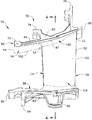
52 翼形ベーン
54 外側バンド
56 内側バンド
60 内側バンドの後方フランジ
62 内側バンドの内表面
64 内側バンドの前方フランジ
66 内側バンドの上流縁部
70 カンチレバー式支持システム
72 前方保持部
74 中間フック組立体
76 後方フック組立体
80 外側バンドの外表面
84 外側バンドの前縁部
86 外側バンドの後縁部
100 翼形ベーンの第1の側壁
102 翼形ベーンの第2の側壁
104 翼形ベーンの前縁
106 翼形ベーンの後縁
140 複合半径フィレット
142 単一半径フィレット
152 外側バンドの内表面
Claims (10)
- ガスタービンエンジン(10)のタービンノズル(50)であって、
外側バンド(54)と、
内側バンド(56)と、
前記外側バンド及び前記内側バンドにより互いに結合され、少なくとも第1の翼形ベーン(114)と第2の翼形ベーン(110)とを含む複数の翼形ベーン(52)と、を含み、
前記第1の翼形ベーンが、該第1の翼形ベーンと前記外側バンドとの間で延びる複合半径フィレット(140)を含み、
前記第2の翼形ベーンが、単一半径フィレット(132)のみにより前記外側バンドに結合されている、
ことを特徴とするタービンノズル(50)。 - 前記複合半径フィレット(140)が、第1の半径(R1)と第2の半径(R2)とを含み、前記第1の半径(R1)が前記第2の半径(R2)より小さいことを特徴とする、請求項1に記載のタービンノズル(50)。
- 前記第1の半径(R1)が、前記第2の半径(R2)と前記外側バンド(54)との間に位置することを特徴とする、請求項2に記載のタービンノズル(50)。
- 前記複合半径フィレット(140)が、前記タービンノズル内での応力集中を低減するのを可能にすることを特徴とする、請求項1に記載のタービンノズル(50)。
- 前記複数の翼形ベーン(52)の各々が、前縁(104)及び後縁(106)において接合された第1の側壁(100)と第2の側壁(102)とを含み、
前記複合半径フィレット(140)が、前記第1の翼形ベーンの第1及び第2の側壁の一方のみに沿って延びている、
ことを特徴とする、請求項1に記載のタービンノズル(50)。 - 前記複数の翼形ベーン(52)が、第3の翼形ベーン(112)を更に含み、
前記第2の翼形ベーンが、前記第1の翼形ベーンと第3の翼形ベーンとの間で前記タービンノズル内に結合され、
前記第3の翼形ベーンが、第2の複合半径フィレット(140)により前記外側バンド(54)に結合されている、
ことを特徴とする、請求項1に記載のタービンノズル(50)。 - 前記複数の翼形ベーン(52)の各々が、前縁(104)及び後縁(106)において接合された第1の側壁(100)と第2の側壁(102)とを含み、
前記複合半径フィレット(140)が、前記第1の翼形ベーンの第1の側壁及び前記第3の翼形ベーンの第2の側壁のみに沿って延びている、
ことを特徴とする、請求項6に記載のタービンノズル(50)。 - 前記複数の翼形ベーン(52)の各々が、単一半径フィレット(130)により前記内側バンド(56)に結合されていることを特徴とする、請求項1に記載のタービンノズル(50)。
- 少なくとも1つのタービンノズル組立体(50)を含むガスタービンエンジン(10)であって、
前記少なくとも1つのタービンノズル組立体が、外側バンド(54)と、内側バンド(56)と、前記外側バンド及び前記内側バンドにより互いに結合された複数の翼形ベーン(52)とを含み、
前記複数の翼形ベーンが、第1の翼形ベーン(114)と、前記第1の翼形ベーンに円周方向に隣接して配置された第2の翼形ベーン(110)とを含み、
前記第1の翼形ベーンが、該第1の翼形ベーンと前記外側バンドとの間で延びる少なくとも1つの複合半径フィレット(140)を含み、
前記第2の翼形ベーンが、該第2の翼形ベーンと前記外側バンドとの間で延びる単一半径フィレット(132)のみを含む、
ことを特徴とするガスタービンエンジン(10)。 - 前記第1の翼形ベーンの複合半径フィレット(140)が、前記タービンノズル(50)内での応力集中を低減するのを可能にすることを特徴とする、請求項9に記載のガスタービンエンジン(10)。
Applications Claiming Priority (1)
| Application Number | Priority Date | Filing Date | Title |
|---|---|---|---|
| US10/325,035 US6921246B2 (en) | 2002-12-20 | 2002-12-20 | Methods and apparatus for assembling gas turbine nozzles |
Publications (3)
| Publication Number | Publication Date |
|---|---|
| JP2004204845A true JP2004204845A (ja) | 2004-07-22 |
| JP2004204845A5 JP2004204845A5 (ja) | 2007-02-08 |
| JP3982628B2 JP3982628B2 (ja) | 2007-09-26 |
Family
ID=32393089
Family Applications (1)
| Application Number | Title | Priority Date | Filing Date |
|---|---|---|---|
| JP2003421873A Expired - Fee Related JP3982628B2 (ja) | 2002-12-20 | 2003-12-19 | ガスタービンノズルを組み立てるための方法及び装置 |
Country Status (5)
| Country | Link |
|---|---|
| US (1) | US6921246B2 (ja) |
| EP (1) | EP1431513B1 (ja) |
| JP (1) | JP3982628B2 (ja) |
| CN (1) | CN100429381C (ja) |
| DE (1) | DE60312466T2 (ja) |
Families Citing this family (24)
| Publication number | Priority date | Publication date | Assignee | Title |
|---|---|---|---|---|
| US6932568B2 (en) * | 2003-02-27 | 2005-08-23 | General Electric Company | Turbine nozzle segment cantilevered mount |
| US6969233B2 (en) * | 2003-02-27 | 2005-11-29 | General Electric Company | Gas turbine engine turbine nozzle segment with a single hollow vane having a bifurcated cavity |
| US7762761B2 (en) * | 2005-11-30 | 2010-07-27 | General Electric Company | Methods and apparatus for assembling turbine nozzles |
| US7360988B2 (en) * | 2005-12-08 | 2008-04-22 | General Electric Company | Methods and apparatus for assembling turbine engines |
| US20070134087A1 (en) * | 2005-12-08 | 2007-06-14 | General Electric Company | Methods and apparatus for assembling turbine engines |
| US7419352B2 (en) * | 2006-10-03 | 2008-09-02 | General Electric Company | Methods and apparatus for assembling turbine engines |
| US7771164B2 (en) * | 2006-12-18 | 2010-08-10 | General Electric Company | Method and system for assembling a turbine engine |
| US8051564B2 (en) | 2007-01-09 | 2011-11-08 | General Electric Company | Methods and apparatus for fabricating a turbine nozzle assembly |
| EP1975373A1 (en) * | 2007-03-06 | 2008-10-01 | Siemens Aktiengesellschaft | Guide vane duct element for a guide vane assembly of a gas turbine engine |
| US20110097205A1 (en) * | 2009-10-28 | 2011-04-28 | General Electric Company | Turbine airfoil-sidewall integration |
| US8454303B2 (en) * | 2010-01-14 | 2013-06-04 | General Electric Company | Turbine nozzle assembly |
| US8671691B2 (en) | 2010-05-26 | 2014-03-18 | General Electric Company | Hybrid prefilming airblast, prevaporizing, lean-premixing dual-fuel nozzle for gas turbine combustor |
| FR2961553B1 (fr) * | 2010-06-18 | 2012-08-31 | Snecma | Secteur angulaire de redresseur pour compresseur de turbomachine, redresseur de turbomachine et turbomachine comprenant un tel secteur |
| US8690530B2 (en) * | 2011-06-27 | 2014-04-08 | General Electric Company | System and method for supporting a nozzle assembly |
| FR2978197B1 (fr) * | 2011-07-22 | 2015-12-25 | Snecma | Distributeur de turbine de turbomachine et turbine comportant un tel distributeur |
| US8920117B2 (en) | 2011-10-07 | 2014-12-30 | Pratt & Whitney Canada Corp. | Fabricated gas turbine duct |
| US9574447B2 (en) * | 2013-09-11 | 2017-02-21 | General Electric Company | Modification process and modified article |
| US20150110617A1 (en) * | 2013-10-23 | 2015-04-23 | General Electric Company | Turbine airfoil including tip fillet |
| US10352180B2 (en) | 2013-10-23 | 2019-07-16 | General Electric Company | Gas turbine nozzle trailing edge fillet |
| US9745864B2 (en) * | 2014-04-16 | 2017-08-29 | United Technologies Corporation | Systems and methods for anti-rotational features |
| EP3186484B1 (en) | 2014-08-29 | 2019-06-05 | Siemens Aktiengesellschaft | Gas turbine engine |
| JP2017537255A (ja) * | 2014-10-28 | 2017-12-14 | シーメンス エナジー インコーポレイテッド | モジュール式のタービンベーン |
| US10107108B2 (en) | 2015-04-29 | 2018-10-23 | General Electric Company | Rotor blade having a flared tip |
| EP3650656A1 (en) * | 2017-09-15 | 2020-05-13 | General Electric Company Polska sp. z o.o. | Inner band assembly for a turbine nozzle |
Family Cites Families (30)
| Publication number | Priority date | Publication date | Assignee | Title |
|---|---|---|---|---|
| US4126405A (en) | 1976-12-16 | 1978-11-21 | General Electric Company | Turbine nozzle |
| US4297077A (en) | 1979-07-09 | 1981-10-27 | Westinghouse Electric Corp. | Cooled turbine vane |
| US4531289A (en) | 1983-01-28 | 1985-07-30 | F. M. Brick Industries, Inc. | High-power rescue tool |
| US4842249A (en) | 1983-09-16 | 1989-06-27 | Weigand George R | Spreader type rescue tool |
| US4522054A (en) | 1983-09-26 | 1985-06-11 | Power Pry Corporation | Emergency rescue apparatus |
| US4732029A (en) | 1985-09-17 | 1988-03-22 | Bertino Joseph E | Accident rescue tool |
| US4869465A (en) | 1986-06-24 | 1989-09-26 | Mordechai Yirmiyahu | Power-operated spreader tool |
| US5289711A (en) | 1991-05-15 | 1994-03-01 | Spiegel Leo J | Apparatus for spreading steel structures |
| US5243761A (en) | 1992-03-18 | 1993-09-14 | Hale Fire Pump Company | Portable rescue tool |
| US5249920A (en) | 1992-07-09 | 1993-10-05 | General Electric Company | Turbine nozzle seal arrangement |
| US5372476A (en) | 1993-06-18 | 1994-12-13 | General Electric Company | Turbine nozzle support assembly |
| US5425260A (en) | 1994-01-27 | 1995-06-20 | Gehron; Michael A. | Accident rescue tool |
| US5662160A (en) | 1995-10-12 | 1997-09-02 | General Electric Co. | Turbine nozzle and related casting method for optimal fillet wall thickness control |
| US5620300A (en) | 1995-11-16 | 1997-04-15 | General Electric Co. | Method of constructing a turbine nozzle to prevent structurally induced excitation forces |
| US5669757A (en) | 1995-11-30 | 1997-09-23 | General Electric Company | Turbine nozzle retainer assembly |
| US5732932A (en) | 1996-03-27 | 1998-03-31 | American Rescue Technology Incorporated | Hydraulic ram attachment for a rescue tool |
| US5875554A (en) | 1996-12-24 | 1999-03-02 | Rescue Technology, Inc. | Rescue tool |
| US5953822A (en) | 1996-12-24 | 1999-09-21 | Rescue Technology, Inc. | Rescue tool |
| US5810333A (en) | 1997-02-06 | 1998-09-22 | Curtiss Wright Flight Systems Inc. | Ram device |
| JP3316418B2 (ja) * | 1997-06-12 | 2002-08-19 | 三菱重工業株式会社 | ガスタービン冷却動翼 |
| EP1086298B1 (en) * | 1998-06-12 | 2004-10-20 | Ebara Corporation | Turbine nozzle vane |
| US6193465B1 (en) | 1998-09-28 | 2001-02-27 | General Electric Company | Trapped insert turbine airfoil |
| US6099245A (en) | 1998-10-30 | 2000-08-08 | General Electric Company | Tandem airfoils |
| US6311537B1 (en) | 1998-10-30 | 2001-11-06 | Orlando C. Vigil | Blade tip for a rescue tool |
| US6164656A (en) | 1999-01-29 | 2000-12-26 | General Electric Company | Turbine nozzle interface seal and methods |
| US6183192B1 (en) * | 1999-03-22 | 2001-02-06 | General Electric Company | Durable turbine nozzle |
| US6272900B1 (en) | 1999-04-21 | 2001-08-14 | Matthew Kobel | Extension ram tip |
| JP3794868B2 (ja) * | 1999-06-15 | 2006-07-12 | 三菱重工業株式会社 | ガスタービン静翼 |
| DE19941134C1 (de) * | 1999-08-30 | 2000-12-28 | Mtu Muenchen Gmbh | Schaufelkranz für eine Gasturbine |
| US6851924B2 (en) * | 2002-09-27 | 2005-02-08 | Siemens Westinghouse Power Corporation | Crack-resistance vane segment member |
-
2002
- 2002-12-20 US US10/325,035 patent/US6921246B2/en not_active Expired - Lifetime
-
2003
- 2003-12-16 EP EP03257927A patent/EP1431513B1/en not_active Expired - Lifetime
- 2003-12-16 DE DE60312466T patent/DE60312466T2/de not_active Expired - Lifetime
- 2003-12-19 JP JP2003421873A patent/JP3982628B2/ja not_active Expired - Fee Related
- 2003-12-22 CN CNB2003101131011A patent/CN100429381C/zh not_active Expired - Fee Related
Also Published As
| Publication number | Publication date |
|---|---|
| US6921246B2 (en) | 2005-07-26 |
| CN1512038A (zh) | 2004-07-14 |
| US20040120810A1 (en) | 2004-06-24 |
| DE60312466T2 (de) | 2007-11-29 |
| JP3982628B2 (ja) | 2007-09-26 |
| EP1431513A2 (en) | 2004-06-23 |
| CN100429381C (zh) | 2008-10-29 |
| EP1431513B1 (en) | 2007-03-14 |
| DE60312466D1 (de) | 2007-04-26 |
| EP1431513A3 (en) | 2005-09-28 |
Similar Documents
| Publication | Publication Date | Title |
|---|---|---|
| JP3982628B2 (ja) | ガスタービンノズルを組み立てるための方法及び装置 | |
| JP4515086B2 (ja) | ガスタービンノズルを組み立てるための方法及び装置 | |
| US8356975B2 (en) | Gas turbine engine with non-axisymmetric surface contoured vane platform | |
| US9976433B2 (en) | Gas turbine engine with non-axisymmetric surface contoured rotor blade platform | |
| US10822973B2 (en) | Shroud for a gas turbine engine | |
| US6932568B2 (en) | Turbine nozzle segment cantilevered mount | |
| JP4785507B2 (ja) | ブルノーズ段部付きタービンノズル | |
| JP6190874B2 (ja) | タービンノズルアウターバンドおよび翼形部冷却装置 | |
| EP1870563B1 (en) | Fluid injection system for a platform | |
| JP2017072128A (ja) | ステータ部品 | |
| US20220356805A1 (en) | Airfoil assembly with a fluid circuit | |
| US20180347375A1 (en) | Airfoil with tip rail cooling | |
| US11549377B2 (en) | Airfoil with cooling hole | |
| JP2017141825A (ja) | ガスタービンエンジン用の翼形部 | |
| CN107461225B (zh) | 用于燃气涡轮发动机的喷嘴冷却系统 | |
| US10443400B2 (en) | Airfoil for a turbine engine | |
| US20180016915A1 (en) | Turbomachine component having a platform cavity with a stress reduction feature | |
| US11377963B2 (en) | Component for a turbine engine with a conduit | |
| EP3822456A1 (en) | Airfoil having a turn channel with split and flow-through |
Legal Events
| Date | Code | Title | Description |
|---|---|---|---|
| A521 | Written amendment |
Free format text: JAPANESE INTERMEDIATE CODE: A523 Effective date: 20061218 |
|
| A621 | Written request for application examination |
Free format text: JAPANESE INTERMEDIATE CODE: A621 Effective date: 20061218 |
|
| A871 | Explanation of circumstances concerning accelerated examination |
Free format text: JAPANESE INTERMEDIATE CODE: A871 Effective date: 20061218 |
|
| A975 | Report on accelerated examination |
Free format text: JAPANESE INTERMEDIATE CODE: A971005 Effective date: 20070126 |
|
| A131 | Notification of reasons for refusal |
Free format text: JAPANESE INTERMEDIATE CODE: A131 Effective date: 20070206 |
|
| A521 | Written amendment |
Free format text: JAPANESE INTERMEDIATE CODE: A523 Effective date: 20070502 |
|
| TRDD | Decision of grant or rejection written | ||
| A01 | Written decision to grant a patent or to grant a registration (utility model) |
Free format text: JAPANESE INTERMEDIATE CODE: A01 Effective date: 20070529 |
|
| A61 | First payment of annual fees (during grant procedure) |
Free format text: JAPANESE INTERMEDIATE CODE: A61 Effective date: 20070627 |
|
| FPAY | Renewal fee payment (event date is renewal date of database) |
Free format text: PAYMENT UNTIL: 20100713 Year of fee payment: 3 |
|
| R150 | Certificate of patent or registration of utility model |
Free format text: JAPANESE INTERMEDIATE CODE: R150 |
|
| FPAY | Renewal fee payment (event date is renewal date of database) |
Free format text: PAYMENT UNTIL: 20110713 Year of fee payment: 4 |
|
| FPAY | Renewal fee payment (event date is renewal date of database) |
Free format text: PAYMENT UNTIL: 20120713 Year of fee payment: 5 |
|
| FPAY | Renewal fee payment (event date is renewal date of database) |
Free format text: PAYMENT UNTIL: 20120713 Year of fee payment: 5 |
|
| FPAY | Renewal fee payment (event date is renewal date of database) |
Free format text: PAYMENT UNTIL: 20130713 Year of fee payment: 6 |
|
| LAPS | Cancellation because of no payment of annual fees |