JP2004209111A - Ultrasonograph - Google Patents
Ultrasonograph Download PDFInfo
- Publication number
- JP2004209111A JP2004209111A JP2003001717A JP2003001717A JP2004209111A JP 2004209111 A JP2004209111 A JP 2004209111A JP 2003001717 A JP2003001717 A JP 2003001717A JP 2003001717 A JP2003001717 A JP 2003001717A JP 2004209111 A JP2004209111 A JP 2004209111A
- Authority
- JP
- Japan
- Prior art keywords
- count value
- transmission
- frequency
- delay
- clock
- Prior art date
- Legal status (The legal status is an assumption and is not a legal conclusion. Google has not performed a legal analysis and makes no representation as to the accuracy of the status listed.)
- Granted
Links
- 230000005540 biological transmission Effects 0.000 claims abstract description 99
- 238000006243 chemical reaction Methods 0.000 claims abstract description 64
- 230000006870 function Effects 0.000 description 18
- 238000010586 diagram Methods 0.000 description 6
- 238000000034 method Methods 0.000 description 6
- 230000000694 effects Effects 0.000 description 2
- 239000004065 semiconductor Substances 0.000 description 2
- 241000255777 Lepidoptera Species 0.000 description 1
- 230000017531 blood circulation Effects 0.000 description 1
- 230000003111 delayed effect Effects 0.000 description 1
- 238000003745 diagnosis Methods 0.000 description 1
Images

Landscapes
- Ultra Sonic Daignosis Equipment (AREA)
Abstract
Description
【0001】
【発明の属する技術分野】
本発明は超音波診断装置に係り、特に送信遅延時間を設定する超音波診断装置に関する。
【0002】
【従来の技術】
生体組織に超音波を送信し、そのエコー信号を処理し例えば断層画像、ドプラ情報等として表示する超音波診断装置では、複数の振動素子からなる超音波振動子により超音波ビームが形成され、この超音波ビームが電子的に走査される。この電子走査を行うため、各振動素子ごとに所定量遅延された送信信号が供給される。
【0003】
図4は、超音波診断装置の送信部10のブロック図である。送信部10は、図示されていない送受信制御部の制御の下で、超音波振動子11の複数の振動素子12a〜12nに、それぞれ対応する送信遅延時間を有する送信駆動信号を供給する。
【0004】
図4において、第1分周器32は、分周比を可変することで複数の周波数を生成する機能を有し、後述するCPU36の制御の下で選ばれた分周比に従ってクロック発生器30の出力を分周しクロック信号46として各カウンタ34a〜34nに対して出力する。例えばクロック発生器30の出力が120MHzのときは、クロック信号46の周波数として40MHz、30MHz、24MHz等を生成できる。
【0005】
各カウンタ34a〜34nは、第1分周器32から入力されるクロック信号46をカウントするカウンタで、初期化信号42によりカウント値をリセットするリセット端子と、送信遅延時間を規定する各遅延カウント値が設定される遅延カウント値設定部40a〜40nとを備えている。遅延カウント値設定部40a〜40nには、後述するCPU36の制御の下で、データ保持部38から各振動素子12a〜12nにそれぞれ対応する各遅延カウント値が出力され設定される。各カウンタ34a〜34nは、初期化信号42の入力後からクロック信号46のカウントを開始し、そのカウント値が設定された遅延カウント値と一致するとカウンタ出力信号48を出力する。
【0006】
第2分周器58はカウンタ出力信号48を分周して所期の送信周波数とする回路である。増幅器60は分周された信号を増幅し送信駆動信号として各振動素子12a〜12nに供給する回路である。第2分周器58を用いることで、クロック信号46の周波数をその分高くでき、遅延カウント値の分解能を上げることができる。
【0007】
CPU36は、各振動素子12a〜12nの送信遅延時間を規定する各遅延カウント値を算出する算出手段としての機能を有する。すなわち第1分周器32で生成可能なクロック信号46の周波数ごとに、各振動素子12a〜12nに対応する各遅延カウント値を算出し、データ保持部38に出力する。
【0008】
データ保持部38は、算出されたすべての遅延カウント値を記憶し保持する。例えば各振動素子12a〜12nに対応して算出された各遅延カウント値を、クロック信号46の周波数ごとに記憶し保持する。したがって、第1分周器32で生成可能な周波数が40MHz、30MHz、24MHz等N種類とすると、N種類の周波数に対応して各振動素子12a〜12nごとの各遅延カウント値がCPU36により算出され、その算出結果がデータ保持部38により記憶される。
【0009】
また、CPU36は、第1分周器32、第2分周器58、データ保持部38と接続され、図示されていない送信周波数選択手段により選択された送信周波数に応じ、第1分周器32、第2分周器58の分周比の指示、およびデータ保持部38の遅延カウント値設定部40a〜40nに対する出力の指示をする機能を有する。送信周波数の選択はユーザの入力で行うこともでき、また、あらかじめ設定された基準、例えば超音波診断装置の機能切り替え順序に従った基準により自動的に選択されてもよい。
【0010】
従来の超音波診断装置の送信部の上記構成においては、次のようにして、各振動素子12a〜12nにそれぞれ対応する送信遅延時間を有する送信駆動信号が供給される。例えば、図示されていない送信周波数選択手段により、超音波の送信周波数が5MHzと選択されたときは、CPU36により、第1分周器32に40MHzの周波数のクロック信号46を生成する指示が与えられ、第2分周器58に1/8分周の指示が与えられる。また、データ保持部38には、各遅延カウント値設定部40a〜40nに40MHzの周波数に対応する各遅延カウント値をそれぞれ出力し設定するよう指示が与えられる。こうして、各カウンタ34a〜34nにおいて、40MHzのクロック信号46をカウントし、そのカウント値が40MHzに対応する遅延カウント値に一致した場合に、各カウンタ出力信号48a〜48nが出力される。各出力信号は、第2分周器58により5MHzに分周され、増幅器60により増幅されて、各振動素子12a〜12nに、それぞれ対応する送信遅延時間を有する5MHzの送信駆動信号が供給される。
【0011】
同様にして、他の送信周波数、例えば3.75MHzの送信周波数が選ばれる場合も、第1分周器32と第2分周器58にそれぞれ適当な分周比の指示が与えられるとともに、データ保持部38に対して各遅延カウント値設定部40a〜40nにクロック信号の周波数に対応する各遅延カウント値をそれぞれ出力するよう指示が与えられる。
【0012】
【発明が解決しようとする課題】
超音波診断装置の機能上、電子走査に必要な各振動素子に対応する遅延カウント数の算出が少ない場合には、データ保持部を設けなくても、CPUが電子走査の速度に合わせて必要な各遅延カウント数を算出できる。また、電子走査に必要な各遅延カウント数の算出が多くて、CPUが電子走査の速度に合わせて必要な各遅延カウント数を算出するのが困難なときは、あらかじめ必要な各遅延カウント数を算出し、上記のデータ保持部に記憶し、必要に応じて読み出すことで電子走査の速度に合わせて必要な各遅延カウント数を得ることができる。
【0013】
ところで、超音波診断装置は、生体組織の断層画像を観察できるBモードのほか、ドプラ効果を用いて血流速度等を計測することができるドプラモードやカラードプラモード等複数の機能を持っているものが増えている。そして、これら複数の機能を切り替えつつ生体組織を診断することが行われる。この場合、それぞれの診断機能に合わせて送信周波数が選ばれるので、機能の切り替えに応じ送信周波数を切り替えるとともに、切り替えられた送信周波数に対応して、遅延カウント値の設定をリアルタイムで切り替える必要がある。
【0014】
このように、各遅延カウント値をリアルタイムで切り替えるためには、切り替えが想定される各機能に用いられる各遅延カウント値のすべてをデータ保持部に記憶し、切り替えに応じて迅速に読み出す必要がある。
【0015】
しかし、電子走査に必要な送信遅延時間のデータは非常に多い。例えば、電子セクタ走査の場合、各振動素子ごとの送信遅延時間は、電子走査の走査角度(ビームアドレス)ごとに必要で、さらにフォーカス位置を変更するためにはフォーカス位置(フォーカス番号)ごとに必要になる。また、超音波振動子の振動素子の構成が異なれば各振動素子ごとの送信遅延時間も異なってくる。そして、切り替えが想定される各機能のうちで最も分解能が高く要求される場合についてのデータを用意しておかなくてはならない。例えばビームアドレスについては、もっとも細かい走査角度ピッチの全ビームアドレスについての各送信遅延時間のデータを用意しておく必要があり、フォーカス位置、振動素子数等についても同様である。
【0016】
しかも、送信遅延時間が同じでも、送信周波数が異なれば、対応する遅延カウント値が相違し、データ保持部に記憶すべき遅延カウント値のデータ量は、送信周波数がN種類あると、N倍に増加する。したがって、データ保持部のメモリ容量は増大し、大容量のメモリが必要となる。また、データ保持部のメモリが大容量化するにつれ、データ読み出し時間が長くかかり、遅延カウント値の切り替えが迅速に行われない。
【0017】
本発明の目的は、かかる従来技術の課題を解決し、送信遅延時間を記憶するメモリの容量を小さくできる超音波診断装置を提供することである。他の目的は、送信遅延時間の設定を迅速に行うことができる超音波診断装置を提供することである。
【0018】
【課題を解決するための手段】
上記目的を達成するため、本発明に係る超音波診断装置は、複数の異なる周波数のクロックの中から選ばれた選定クロックをカウントし、そのカウント値と送信遅延時間を決定するために設定された遅延カウント値とが一致した場合に、前記選定クロックを出力し、その出力に基づいて送信周波数の送信パルスを生成する制御回路と、前記送信パルスに基づいて超音波振動子に供給する送信駆動パルスを生成する送信回路と、を有する送信部を含む超音波診断装置において、送信遅延時間を基準周波数のクロックのカウント値に置き換える算出手段と、基準カウント値が示す時間を前記選定クロックのカウント値に換算し、その換算されたカウント値を前記送信遅延時間の決定のための遅延カウント値として設定する手段と、を備えることを特徴とする。
【0019】
また、本発明に係る超音波診断装置は、超音波を送受波する複数の振動素子と、前記各振動素子ごとに、複数の異なる周波数のクロックの中から選ばれた選定クロックをカウントし、そのカウント値と、各振動素子に対応する各送信遅延時間を決定するために設定された各遅延カウント値とが一致した場合に、前記選定クロックをそれぞれ出力し、その各出力に基づいて送信周波数の各送信パルスを生成する制御回路と、各送信パルスに基づいて、前記各振動素子に供給する各送信駆動パルスを生成する送信回路と、を有する送信部を含む超音波診断装置において、前記各振動素子ごとに、各送信遅延時間を基準周波数のクロックのカウント値に置き換える算出手段と、前記各振動素子ごとに、基準周波数のクロックのカウント値が示す時間を前記選定クロックのカウント値に換算し、その換算されたカウント値を前記送信遅延時間の決定のための遅延カウント値として設定する手段と、を備えることを特徴とする。
【0020】
かかる構成により、基準周波数以外の周波数に対応した遅延カウント値に対しては、周波数の逓倍あるいは分周関係等の線形換算による換算手段を用いて基準周波数のクロックのカウント値から換算できるので、予め算出して記憶する必要があるのは、基準周波数に対応したカウント値だけになる。したがって送信遅延時間に関するメモリの容量を小さくできる。
【0021】
基準周波数は、前記複数の周波数の中のいずれかの周波数でもよく、また、それら以外の周波数を基準周波数と定めることもできる。
【0022】
また、前記遅延カウント値へ換算する手段は、前記基準周波数のクロックのカウント値と、前記複数の異なる周波数の各クロックに対応する遅延カウント値との間の換算テーブルであり、前記選定クロックの周波数と、前記基準周波数のクロックのカウント値とを入力し、前記選定クロックに対応する遅延カウント値を出力するメモリであることが好ましい。同じ送信遅延時間に対応する遅延カウント値のクロックの周波数による相違は、単に周波数の逓倍あるいは分周関係から定まる周波数の比のみである。したがって、遅延カウント値へ換算する手段には、基準周波数と選定周波数の比を基準周波数のクロックのカウント値に対応して換算するための換算テーブルあるいはメモリを用いることができる。例えばRAM等の半導体メモリを用いることができる。
【0023】
また、前記基準周波数のクロックのカウント値を表すビット数が、前記選定クロックに対応する遅延カウント値を表すビット数より多いことが好ましい。例えば、基準周波数のクロックのカウント値を表すビット数を選定周波数に対応する遅延カウント値を表すビット数よりmbit増やして用いることができる。mは1以上の整数の中で選ぶことができる。このことで、基準周波数と選定周波数との比が割り切れない等の場合でも、基準周波数のクロックのカウント値から選定周波数に対応する遅延カウント値への換算をより正確に行うことができる。
【0024】
【発明の実施の形態】
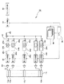
以下に図面を用いて、本発明の実施の形態につき詳細に説明する。図1は、超音波診断装置の送信部70のブロック図である。図4と共通の要素については同一の符号を付し、説明を省略する。
【0025】
図1において、第1分周器32は、CPU36の制御の下で選ばれた分周比に従ってクロック発生器30の出力を分周し、選定周波数のクロックを出力する機能を有する分周回路である。選定周波数のクロックは、クロック信号46として各カウンタ34a〜34nに入力される。例えばクロック発生器30の出力が120MHzのときは、選定周波数は、120MHzから分周可能な40MHz、30MHz、24MHz等の複数の周波数の中から選ばれる。
【0026】
各カウンタ34a〜34nは、第1分周器32から入力されるクロック信号46をカウントするカウンタで、初期化信号42によりカウント値をリセットするリセット端子と、送信遅延時間を規定する各遅延カウント値が設定される遅延カウント値設定部40a〜40nとを備えている。遅延カウント値設定部40a〜40nには、後述するCPU36の制御の下で、換算テーブル74から各振動素子12a〜12nにそれぞれ対応する各遅延カウント値が出力されてそれぞれ設定される。各カウンタ34a〜34nは、初期化信号42の入力後からクロック信号46のカウントを開始し、そのカウント値が設定された遅延カウント値と一致するとカウンタ出力信号48を出力する。
【0027】
第2分周器58はカウンタ出力信号48を分周して所期の送信周波数とする回路であり、増幅器60は分周された信号を増幅し送信駆動信号として各振動素子12a〜12nに供給する回路である。
【0028】
CPU36は、基準周波数に対応する基準遅延カウント値を算出する算出手段としての機能を有する。ここで、基準遅延カウント値とは、送信遅延時間を基準周波数のクロックのカウント値で示したものである。基準周波数は、第1分周器32により生成可能な複数の周波数の中のいずれかの周波数を選んで定めてもよく、あるいはそれら以外の周波数を基準周波数として定めてもよい。基準周波数は後述する換算テーブルの換算の基準となるので、周波数が高いほど換算を正確に行うことができる。例えば、40MHzを基準周波数として定めることができる。基準遅延カウント値は、各振動素子12a〜12nに対応して算出され、算出結果は基準遅延カウント値保持メモリ72に出力され、記憶される。基準遅延カウント値保持メモリ72は、CPU36の制御の下で、換算テーブル74の換算に際して、記憶した各基準遅延カウント値を換算テーブル74に出力する。
【0029】
また、CPU36は、第1分周器32、第2分周器58および換算テーブル74と接続され、図示されていない送信周波数選択手段により選択された送信周波数に応じ、第1分周器32、第2分周器58の分周比の指示、および換算テーブル74においてどの換算を用いるかの指示をする機能を有する。送信周波数の選択はユーザの入力で行うこともでき、また、あらかじめ設定された基準、例えば超音波診断装置の機能切り替え順序に従った基準により自動的に選択されてもよい。
【0030】
換算テーブル74は、基準遅延カウント値を選定周波数に対応した遅延カウント値に換算する換算手段としての機能を有する。すなわち、CPU36の制御の下で、基準遅延カウント値保持メモリ72から出力された各基準遅延カウント値を、選定周波数に対応した各遅延カウント値に換算し、その換算された各遅延カウント値を対応する各カウンタの遅延カウント値設定部40a〜40nにそれぞれ出力して設定する。選定周波数が基準周波数と同じ周波数に選ばれたときは、換算テーブル74は換算を行わず、基準遅延カウント値をそのまま各カウンタの各遅延カウント値設定部40a〜40nに出力し設定する。
【0031】
同じ送信遅延時間でも、クロックの周波数により遅延カウント値は異なるが、その相違は、単に周波数の逓倍あるいは分周関係による周波数の比であるので、線形換算を用いて容易に換算ができる。例えば上記の例で、基準周波数を40MHzとし、選定周波数については30MHzと24MHzの中から選ばれるとすると、40MHz−30MHz間の換算には30/40が換算定数として用いられ、40MHz−24MHz間の換算には24/40が換算定数として用いられる。換算テーブル74の具体的内容は後述する。
【0032】
本発明に係る実施の形態における超音波診断装置の送信部の上記構成においては、次のようにして、各振動素子12a〜12nにそれぞれ対応する送信遅延時間を有する送信駆動信号が供給される。例えば、図示されていない送信周波数選択手段により、超音波の送信周波数が5MHzと選択されたときは、CPU36により、第1分周器32に40MHzの周波数のクロック信号46を生成する指示が与えられ、第2分周器58に1/8分周の指示が与えられる。また、基準周波数が40MHzであるとすると、選定周波数は基準周波数と同じなので、この場合、換算テーブル74には、換算せずに基準遅延カウント値保持メモリ72の出力をそのまま各カウンタ34a〜34nの遅延カウント値設定部40a〜40nに設定する指示が出される。こうして、各カウンタ34a〜34nにおいて、40MHzのクロック信号46をカウントし、そのカウント値が40MHzに対応する遅延カウント値に一致した場合に、各カウンタ出力信号48a〜48nが出力される。各出力信号は、第2分周器58により5MHzに分周され、増幅器60により増幅されて、各振動素子12a〜12nには、それぞれ対応する送信遅延時間を有する5MHzの送信駆動信号が供給される。
【0033】
つぎに、超音波診断装置の機能が切り替わり、送信周波数を3.75MHzにする必要がある場合には、CPU36により、第1分周器32に30MHzの周波数のクロック信号46を生成する指示が与えられ、第2分周器58に1/8分周の指示が与えられる。また、換算テーブル74には40MHz−30MHzの換算の指示が出される。換算テーブル74は、40MHz−30MHzの線形換算により、基準遅延カウント値保持メモリ72から出力された各基準遅延カウント値を、30MHzに対応する遅延カウント値に換算し、その換算値を各カウンタ34a〜34nの遅延カウント値設定部40a〜40nに出力し設定する。こうして、各カウンタ34a〜34nにおいて、30MHzのクロック信号46をカウントし、そのカウント値が30MHzに対応する遅延カウント値に一致した場合に、各カウンタ出力信号48a〜48nが出力される。各出力信号は、第2分周器58により3.75MHzに分周され、増幅器60により増幅されて、各振動素子12a〜12nには、それぞれ対応する送信遅延時間を有する3.75MHzの送信駆動信号が供給される。
【0034】
同様にして、これ以外の送信周波数が選ばれる場合も、第1分周器32と第2分周器58に分周比の指示が与えられるとともに、換算テーブル74に基準遅延カウント値と選定周波数に対応する遅延カウント値との換算の指示が与えられる。
【0035】
このように、基準周波数に対応する基準遅延カウント値を、例えば、各振動素子ごと、各ビームアドレスごと、各フォーカス深さごと等につき予め算出してメモリに記憶しておけば、他の周波数に対応した遅延カウント値については、この基準遅延カウント値を用いて周波数の相違に応じて換算をするだけでよく、全ての周波数に対応する遅延カウント値をメモリに保持する必要がない。したがって送信遅延時間に関するメモリの容量を小さくできる。
【0036】
また、超音波装置の機能が切り替わったときも、換算テーブルにより、対応する遅延カウント値を換算するだけなので、迅速に遅延カウント値の設定を切り替えることができる。
【0037】
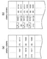
図2は、換算テーブル74の内容の例である。換算テーブル74は、基準周波数40MHzに対応する基準遅延カウント値と選定周波数30MHzに対応する遅延カウント値との間の換算に用いられる40MHz−30MHz用換算表90aと、基準周波数40MHzに対応する基準遅延カウント値と選定周波数24MHzに対応する遅延カウント値との間の換算に用いられる40MHz−24MHz用換算表90bとからなる。40MHz−30MHz用換算表90aも40MHz−24MHz用換算表90bも、左右2欄の構成を有し、左欄に基準遅延カウント値92が、右欄に基準遅延カウント値に対応する遅延カウント値94a,94bが示される。
【0038】
左欄には、基準遅延カウント値を表すビット数で表現できる最小値から最大値までの全ての値が示される。例えば、基準遅延カウント値を表すビット数を10bitsとすれば、2の10乗個の基準遅延カウント値が最小値から最大値まで順に並べられる。図では、説明の便宜上10進法の表記を用い、換算には四捨五入法を採用した。例えば、40MHz−30MHz用換算表90aで説明すると、基準遅延カウント値を20として、これに対応する遅延カウント値は15であるとして換算される。このときの送信遅延時間は、20*25nsec=15*33.3nsec=500nsecである。40MHz−24MHz用換算表90bも同様の構成で、例えば基準遅延カウント値を20として、これに対応する遅延カウント値は12であるとして換算される。
【0039】
図2の換算テーブルの内容は例示であって、換算テーブルを選定周波数ごとの換算表の集合とせずに、一つの表で、例えば最左欄に40MHzの基準遅延カウント値を並べ、左側から2番目の欄に30MHzに対応する遅延カウント値、左側から3番目の欄に24MHzに対応する遅延カウント値等を並べる形式でもよい。また、全ての基準遅延カウント値に対し換算できる万能換算形式のほか、現実に使用される基準遅延カウント値の種類が限定される等のときは、限定された基準遅延カウント値の種類についてのみの限定換算形式であってもよい。さらに、換算表のようなテーブル形式で、基準遅延カウント値を検索し、対応する遅延カウント値を出力するテーブル検索手段を用いるほか、選定周波数と基準遅延カウント値を入力して選定周波数に対応する遅延カウント値を出力するメモリ、例えばROM等の半導体メモリでもよい。
【0040】
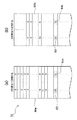
図3は、換算テーブルにおいて、基準遅延カウント値を表すビット数を、選定周波数に対応する遅延カウント値を表すビット数より多くしたときの例である。このようにすることで、換算がより正確になる。図においては説明の便宜上30MHzの選定周波数に対応する遅延カウント値を表すビット数を4bitsとし、40MHzの基準周波数に対応する基準遅延カウント値を表すビット数を(a)においては遅延カウント値を表すビット数と同じ4bits、(b)においては下位ビットを1bit多くして全体で5bitsとした。図3では、ビット数の説明のために2進法で表記したが、原理説明には10進法の表記によるほうが便利なので、10進法のときのカウント数を括弧で併記し、以下の説明でも、10進法で表記した値を用いる。但し、下位ビットの有無は、例えば(9+1ビット)と(9)等の違いで示した。
【0041】
例えば、基準遅延カウント値が9と10との間にあるときに、4bitsを用いる方法と5bitsを用いる方法を比較すると、前者では例えば四捨五入により基準遅延カウント値を10と丸めて、これについて換算するので、(a)に示すように、対応する遅延カウント値は8となる。これに対し、5bitsを用いる後者の方法では、基準遅延カウント値を丸めずにそのまま(9+1ビット)として、換算テーブルにより換算するので、(b)に示すように、対応する遅延カウント値は7となり、より正確な換算結果が得られる。同様に、基準遅延カウント値が8と9の間のときも、4bitsを用いる方法と5bitsを用いる方法で差が生じ、後者の方がより正確な換算結果となる。
【0042】
上記の説明では、基準遅延カウント値を表すビット数を、選定周波数に対応する遅延カウント値を表すビット数より1ビット増やした場合であるが、さらにビット数を増やすこともできる。このように、基準遅延カウント値を表すビット数を選定周波数に対応する遅延カウント数を表すビット数より大きくすることで、換算をより正確に行うことができる。
【0043】
【発明の効果】
本発明に係る超音波診断装置によれば、送信遅延時間を記憶するメモリの容量を小さくできる。
【図面の簡単な説明】
【図1】本発明に係る実施の形態の超音波診断装置の送信部のブロック図である。
【図2】換算テーブルの内容の例を示す図である。
【図3】基準遅延カウント値を表すビット数を増やした場合の換算を説明する図である。
【図4】従来技術の超音波装置の送信部のブロック図である。
【符号の説明】
10,70 超音波診断装置の送信部、11 超音波振動子、12a〜12n振動素子、32 分周器(選定クロック出力手段)、34a〜34n カウンタ、36 CPU(算出手段)、40a〜40n 遅延カウント値設定部、46クロック信号、48a〜48n カウンタ出力信号、72 基準遅延カウント値保持メモリ、74 換算テーブル(換算手段)、92 基準遅延カウント値、94a,94b 対応する遅延カウント値。[0001]
TECHNICAL FIELD OF THE INVENTION
The present invention relates to an ultrasonic diagnostic apparatus, and more particularly, to an ultrasonic diagnostic apparatus for setting a transmission delay time.
[0002]
[Prior art]
In an ultrasonic diagnostic apparatus that transmits an ultrasonic wave to a living tissue, processes the echo signal and displays the echo signal as, for example, a tomographic image, Doppler information, etc., an ultrasonic beam is formed by an ultrasonic vibrator including a plurality of vibrating elements. The ultrasonic beam is electronically scanned. In order to perform this electronic scanning, a transmission signal delayed by a predetermined amount is supplied to each vibration element.
[0003]
FIG. 4 is a block diagram of the
[0004]
In FIG. 4, a
[0005]
Each of the
[0006]
The
[0007]
The
[0008]
The data holding unit 38 stores and holds all calculated delay count values. For example, each delay count value calculated corresponding to each of the
[0009]
Further, the
[0010]
In the above configuration of the transmission unit of the conventional ultrasonic diagnostic apparatus, a transmission drive signal having a transmission delay time corresponding to each of the
[0011]
Similarly, when another transmission frequency, for example, a transmission frequency of 3.75 MHz is selected, an instruction of an appropriate frequency division ratio is given to the
[0012]
[Problems to be solved by the invention]
Due to the function of the ultrasonic diagnostic apparatus, if the calculation of the delay count corresponding to each vibration element required for electronic scanning is small, the CPU is required to match the electronic scanning speed without providing a data holding unit. Each delay count can be calculated. In addition, when the calculation of each delay count required for electronic scanning is large and it is difficult for the CPU to calculate each delay count required in accordance with the speed of electronic scanning, each delay count required in advance is calculated. By calculating, storing the data in the data holding unit, and reading out the data as needed, it is possible to obtain each required delay count in accordance with the speed of electronic scanning.
[0013]
Incidentally, the ultrasonic diagnostic apparatus has a plurality of functions such as a Doppler mode and a color Doppler mode in which a blood flow velocity or the like can be measured using the Doppler effect, in addition to a B mode in which a tomographic image of a living tissue can be observed. Things are increasing. Diagnosis of the living tissue is performed while switching these functions. In this case, since the transmission frequency is selected according to each diagnostic function, it is necessary to switch the transmission frequency in accordance with the switching of the function, and to switch the setting of the delay count value in real time according to the switched transmission frequency. .
[0014]
As described above, in order to switch each delay count value in real time, it is necessary to store all the delay count values used for each function to be switched in the data holding unit and quickly read out the data in accordance with the switching. .
[0015]
However, transmission delay time data necessary for electronic scanning is very large. For example, in the case of electronic sector scanning, a transmission delay time for each vibration element is required for each scanning angle (beam address) of electronic scanning, and further for each focus position (focus number) to change the focus position. become. Further, if the configuration of the vibration element of the ultrasonic transducer is different, the transmission delay time of each vibration element is also different. Then, it is necessary to prepare data on the case where the highest resolution is required among the functions that are assumed to be switched. For example, as for the beam address, it is necessary to prepare data of each transmission delay time for all beam addresses of the finest scanning angle pitch, and the same applies to the focus position, the number of vibrating elements, and the like.
[0016]
In addition, even if the transmission delay time is the same, if the transmission frequency is different, the corresponding delay count value will be different, and the data amount of the delay count value to be stored in the data holding unit will be N times as large as N transmission frequencies. To increase. Therefore, the memory capacity of the data holding unit increases, and a large-capacity memory is required. Further, as the capacity of the memory of the data holding unit increases, the data reading time increases, and the delay count value is not quickly switched.
[0017]
An object of the present invention is to solve the problem of the related art and to provide an ultrasonic diagnostic apparatus capable of reducing the capacity of a memory for storing a transmission delay time. Another object is to provide an ultrasonic diagnostic apparatus that can quickly set a transmission delay time.
[0018]
[Means for Solving the Problems]
To achieve the above object, the ultrasonic diagnostic apparatus according to the present invention counts a selected clock selected from a plurality of clocks of different frequencies, and is set to determine the count value and the transmission delay time. A control circuit that outputs the selected clock when the delay count value matches, generates a transmission pulse of a transmission frequency based on the output, and a transmission drive pulse that is supplied to an ultrasonic transducer based on the transmission pulse. A transmission circuit that generates a clock signal, a calculating unit that replaces a transmission delay time with a count value of a clock of a reference frequency, and a time indicated by the reference count value as a count value of the selected clock. Means for setting the converted count value as a delay count value for determining the transmission delay time. And butterflies.
[0019]
Further, the ultrasonic diagnostic apparatus according to the present invention, a plurality of vibrating elements for transmitting and receiving ultrasonic waves, and for each of the vibrating elements, count a selected clock selected from a plurality of clocks of different frequencies, the When the count value matches each delay count value set for determining each transmission delay time corresponding to each vibration element, the selected clock is output, and the transmission frequency is determined based on each output. In an ultrasonic diagnostic apparatus including a transmission unit having: a control circuit that generates each transmission pulse; and a transmission circuit that generates each transmission drive pulse to be supplied to each of the vibration elements based on each transmission pulse. Calculating means for replacing each transmission delay time with a reference frequency clock count value for each element; and a time indicated by the reference frequency clock count value for each vibrating element. The terms of the count value of the selected clock, characterized in that it comprises means for setting the converted count value as the delay count value for determining the transmission delay time, the.
[0020]
With this configuration, the delay count value corresponding to a frequency other than the reference frequency can be converted from the count value of the clock of the reference frequency by using a conversion unit that performs linear conversion such as frequency multiplication or frequency division. Only the count value corresponding to the reference frequency needs to be calculated and stored. Therefore, the capacity of the memory relating to the transmission delay time can be reduced.
[0021]
The reference frequency may be any one of the plurality of frequencies, and another frequency may be defined as the reference frequency.
[0022]
Further, the means for converting to the delay count value is a conversion table between a count value of the clock of the reference frequency and a delay count value corresponding to each of the plurality of clocks of different frequencies. And a count value of the clock of the reference frequency, and a memory that outputs a delay count value corresponding to the selected clock. The difference of the delay count value corresponding to the same transmission delay time depending on the clock frequency is only the frequency ratio determined from the frequency multiplication or frequency division relationship. Therefore, a conversion table or a memory for converting the ratio between the reference frequency and the selected frequency corresponding to the count value of the clock of the reference frequency can be used as the means for converting into the delay count value. For example, a semiconductor memory such as a RAM can be used.
[0023]
Further, it is preferable that the number of bits representing the count value of the clock of the reference frequency is larger than the number of bits representing the delay count value corresponding to the selected clock. For example, the number of bits representing the count value of the clock of the reference frequency can be used by increasing the number of bits representing the delay count value corresponding to the selected frequency by m bits. m can be selected from one or more integers. Thus, even when the ratio between the reference frequency and the selected frequency cannot be divided, the conversion of the clock count value of the reference frequency to the delay count value corresponding to the selected frequency can be performed more accurately.
[0024]
BEST MODE FOR CARRYING OUT THE INVENTION
Hereinafter, embodiments of the present invention will be described in detail with reference to the drawings. FIG. 1 is a block diagram of the
[0025]
In FIG. 1, a
[0026]
Each of the
[0027]
The
[0028]
The
[0029]
The
[0030]
The conversion table 74 has a function as conversion means for converting the reference delay count value into a delay count value corresponding to the selected frequency. That is, under the control of the
[0031]
Even for the same transmission delay time, the delay count value differs depending on the clock frequency, but the difference is simply the frequency ratio based on the frequency multiplication or frequency division relationship, so that the conversion can be easily performed using linear conversion. For example, in the above example, assuming that the reference frequency is 40 MHz and the selected frequency is selected from 30 MHz and 24 MHz, 30/40 is used as a conversion constant for conversion between 40 MHz and 30 MHz, and between 40 MHz and 24 MHz. For the conversion, 24/40 is used as a conversion constant. The specific contents of the conversion table 74 will be described later.
[0032]
In the above configuration of the transmission unit of the ultrasonic diagnostic apparatus according to the embodiment of the present invention, a transmission drive signal having a transmission delay time corresponding to each of the
[0033]
Next, when the function of the ultrasonic diagnostic apparatus is switched and the transmission frequency needs to be 3.75 MHz, the
[0034]
Similarly, when another transmission frequency is selected, an instruction of the division ratio is given to the
[0035]
In this way, if the reference delay count value corresponding to the reference frequency is calculated in advance for each of the vibrating elements, for each of the beam addresses, for each of the focus depths and the like and stored in the memory, the reference delay count value for other frequencies can be obtained. It is only necessary to convert the corresponding delay count value according to the difference in frequency using this reference delay count value, and it is not necessary to hold the delay count values corresponding to all frequencies in the memory. Therefore, the capacity of the memory relating to the transmission delay time can be reduced.
[0036]
Also, when the function of the ultrasonic apparatus is switched, only the corresponding delay count value is converted by the conversion table, so that the setting of the delay count value can be quickly switched.
[0037]
FIG. 2 is an example of the contents of the conversion table 74. The conversion table 74 includes a conversion table 90a for 40 MHz-30 MHz used for conversion between a reference delay count value corresponding to the reference frequency 40 MHz and a delay count value corresponding to the selected
[0038]
The left column shows all values from the minimum value to the maximum value that can be represented by the number of bits representing the reference delay count value. For example, if the number of bits representing the reference delay count value is 10 bits, 2 10 reference delay count values are arranged in order from the minimum value to the maximum value. In the figure, decimal notation is used for convenience of explanation, and rounding is used for conversion. For example, in the case of a conversion table 90a for 40 MHz-30 MHz, the reference delay count value is set to 20, and the corresponding delay count value is set to 15 for conversion. The transmission delay time at this time is 20 * 25 nsec = 15 * 33.3 nsec = 500 nsec. The conversion table 90b for 40 MHz to 24 MHz has the same configuration. For example, the reference delay count value is set to 20, and the corresponding delay count value is set to 12 for conversion.
[0039]
The content of the conversion table in FIG. 2 is an example. Instead of using the conversion table as a set of conversion tables for each selected frequency, in one table, for example, a reference delay count value of 40 MHz is arranged in the leftmost column, and 2 A format in which delay count values corresponding to 30 MHz are arranged in the third column and delay count values corresponding to 24 MHz in the third column from the left may be used. In addition to the universal conversion format that can convert all reference delay count values, when the type of reference delay count value actually used is limited, etc., only the type of the limited reference delay count value is used. The conversion format may be limited. Further, in addition to using a table search means for searching for a reference delay count value in a table format such as a conversion table and outputting a corresponding delay count value, a selected frequency and a reference delay count value are inputted to correspond to the selected frequency. A memory that outputs the delay count value, for example, a semiconductor memory such as a ROM may be used.
[0040]
FIG. 3 shows an example in which, in the conversion table, the number of bits representing the reference delay count value is larger than the number of bits representing the delay count value corresponding to the selected frequency. In this way, the conversion becomes more accurate. In the figure, for convenience of explanation, the number of bits representing the delay count value corresponding to the selected frequency of 30 MHz is 4 bits, and the number of bits representing the reference delay count value corresponding to the reference frequency of 40 MHz represents the delay count value in (a). In the case of 4 bits, which is the same as the number of bits, and in (b), the number of lower bits is increased by 1 bit to be 5 bits in total. In FIG. 3, the number of bits is described in binary notation, but it is more convenient to use decimal notation for explanation of the principle, so the count number in decimal notation is also written in parentheses, and the following description is given. However, a value expressed in a decimal system is used. However, the presence / absence of lower bits is indicated by, for example, a difference between (9 + 1 bit) and (9).
[0041]
For example, when the method using 4 bits is compared with the method using 5 bits when the reference delay count value is between 9 and 10, in the former, the reference delay count value is rounded to 10 by, for example, rounding, and this is converted. Therefore, the corresponding delay count value is 8, as shown in FIG. On the other hand, in the latter method using 5 bits, the reference delay count value is converted (9 + 1 bits) as it is without rounding using the conversion table, so that the corresponding delay count value becomes 7 as shown in (b). , A more accurate conversion result can be obtained. Similarly, when the reference delay count value is between 8 and 9, a difference occurs between the method using 4 bits and the method using 5 bits, and the latter results in a more accurate conversion result.
[0042]
In the above description, the number of bits representing the reference delay count value is increased by one bit from the number of bits representing the delay count value corresponding to the selected frequency. However, the number of bits can be further increased. By making the number of bits representing the reference delay count value larger than the number of bits representing the delay count number corresponding to the selected frequency, conversion can be performed more accurately.
[0043]
【The invention's effect】
According to the ultrasonic diagnostic apparatus of the present invention, the capacity of the memory that stores the transmission delay time can be reduced.
[Brief description of the drawings]
FIG. 1 is a block diagram of a transmission unit of an ultrasonic diagnostic apparatus according to an embodiment of the present invention.
FIG. 2 is a diagram showing an example of the contents of a conversion table.
FIG. 3 is a diagram illustrating conversion when the number of bits representing a reference delay count value is increased.
FIG. 4 is a block diagram of a transmission unit of a conventional ultrasonic device.
[Explanation of symbols]
10, 70 Transmitter of ultrasonic diagnostic apparatus, 11 ultrasonic transducer, 12a to 12n vibrating element, 32 frequency divider (selected clock output means), 34a to 34n counter, 36 CPU (calculation means), 40a to 40n delay Count value setting section, 46 clock signal, 48a to 48n counter output signal, 72 reference delay count value holding memory, 74 conversion table (conversion means), 92 reference delay count value, 94a, 94b corresponding delay count value.
Claims (4)
前記送信パルスに基づいて超音波振動子に供給する送信駆動パルスを生成する送信回路と、
を有する送信部を含む超音波診断装置において、
送信遅延時間を基準周波数のクロックのカウント値に置き換える算出手段と、
基準カウント値が示す時間を前記選定クロックのカウント値に換算し、その換算されたカウント値を前記送信遅延時間の決定のための遅延カウント値として設定する手段と、
を備えることを特徴とする超音波診断装置。Count a selected clock selected from a plurality of clocks of different frequencies, and when the count value matches the delay count value set for determining the transmission delay time, output the selected clock; A control circuit for generating a transmission pulse of a transmission frequency based on the output,
A transmission circuit that generates a transmission drive pulse to be supplied to the ultrasonic transducer based on the transmission pulse,
An ultrasonic diagnostic apparatus including a transmission unit having
Calculating means for replacing the transmission delay time with the count value of the clock of the reference frequency;
Means for converting a time indicated by a reference count value into a count value of the selected clock, and setting the converted count value as a delay count value for determining the transmission delay time;
An ultrasonic diagnostic apparatus comprising:
前記各振動素子ごとに、複数の異なる周波数のクロックの中から選ばれた選定クロックをカウントし、そのカウント値と、各振動素子に対応する各送信遅延時間を決定するために設定された各遅延カウント値とが一致した場合に、前記選定クロックをそれぞれ出力し、その各出力に基づいて送信周波数の各送信パルスを生成する制御回路と、
各送信パルスに基づいて、前記各振動素子に供給する各送信駆動パルスを生成する送信回路と、
を有する送信部を含む超音波診断装置において、
前記各振動素子ごとに、各送信遅延時間を基準周波数のクロックのカウント値に置き換える算出手段と、
前記各振動素子ごとに、基準周波数のクロックのカウント値が示す時間を前記選定クロックのカウント値に換算し、その換算されたカウント値を前記送信遅延時間の決定のための遅延カウント値として設定する手段と、
を備えることを特徴とする超音波診断装置。A plurality of vibrating elements for transmitting and receiving ultrasonic waves,
For each of the vibrating elements, count a selected clock selected from a plurality of clocks of different frequencies, count the value, and set each delay set to determine each transmission delay time corresponding to each of the vibrating elements. A control circuit that, when the count value matches, outputs the selected clock, and generates each transmission pulse of the transmission frequency based on each output;
A transmission circuit that generates each transmission drive pulse to be supplied to each of the vibration elements based on each transmission pulse,
An ultrasonic diagnostic apparatus including a transmission unit having
For each of the vibrating elements, a calculating unit that replaces each transmission delay time with a count value of a clock of a reference frequency,
For each of the vibrating elements, the time indicated by the count value of the clock of the reference frequency is converted into the count value of the selected clock, and the converted count value is set as a delay count value for determining the transmission delay time. Means,
An ultrasonic diagnostic apparatus comprising:
前記遅延カウント値へ換算する手段は、前記基準周波数のクロックのカウント値と、前記複数の異なる周波数の各クロックに対応する遅延カウント値との間の換算テーブルであり、前記選定クロックの周波数と、前記基準周波数のクロックのカウント値とを入力し、前記選定クロックに対応する遅延カウント値を出力するメモリであることを特徴とする超音波診断装置。In the ultrasonic diagnostic apparatus according to claim 1 or 2,
The means for converting to the delay count value is a conversion table between the count value of the clock of the reference frequency and the delay count value corresponding to each clock of the plurality of different frequencies, and the frequency of the selected clock, An ultrasonic diagnostic apparatus comprising: a memory for receiving a count value of a clock of the reference frequency and outputting a delay count value corresponding to the selected clock.
前記基準周波数のクロックのカウント値を表すビット数が、前記選定クロックに対応する遅延カウント値を表すビット数より多いことを特徴とする超音波診断装置。In the ultrasonic diagnostic apparatus according to claim 1 or 2,
An ultrasonic diagnostic apparatus, wherein the number of bits representing the count value of the clock of the reference frequency is larger than the number of bits representing the delay count value corresponding to the selected clock.
Priority Applications (1)
| Application Number | Priority Date | Filing Date | Title |
|---|---|---|---|
| JP2003001717A JP3944084B2 (en) | 2003-01-08 | 2003-01-08 | Ultrasonic diagnostic equipment |
Applications Claiming Priority (1)
| Application Number | Priority Date | Filing Date | Title |
|---|---|---|---|
| JP2003001717A JP3944084B2 (en) | 2003-01-08 | 2003-01-08 | Ultrasonic diagnostic equipment |
Publications (2)
| Publication Number | Publication Date |
|---|---|
| JP2004209111A true JP2004209111A (en) | 2004-07-29 |
| JP3944084B2 JP3944084B2 (en) | 2007-07-11 |
Family
ID=32819663
Family Applications (1)
| Application Number | Title | Priority Date | Filing Date |
|---|---|---|---|
| JP2003001717A Expired - Fee Related JP3944084B2 (en) | 2003-01-08 | 2003-01-08 | Ultrasonic diagnostic equipment |
Country Status (1)
| Country | Link |
|---|---|
| JP (1) | JP3944084B2 (en) |
Cited By (2)
| Publication number | Priority date | Publication date | Assignee | Title |
|---|---|---|---|---|
| WO2010029890A1 (en) * | 2008-09-09 | 2010-03-18 | オリンパスメディカルシステムズ株式会社 | Ultrasonographic device and ultrasonographic device focal point position control method |
| CN114848017A (en) * | 2021-01-20 | 2022-08-05 | 富士胶片医疗健康株式会社 | Ultrasonic imaging apparatus, signal processing apparatus, and signal processing method |
-
2003
- 2003-01-08 JP JP2003001717A patent/JP3944084B2/en not_active Expired - Fee Related
Cited By (3)
| Publication number | Priority date | Publication date | Assignee | Title |
|---|---|---|---|---|
| WO2010029890A1 (en) * | 2008-09-09 | 2010-03-18 | オリンパスメディカルシステムズ株式会社 | Ultrasonographic device and ultrasonographic device focal point position control method |
| JP2010063543A (en) * | 2008-09-09 | 2010-03-25 | Olympus Medical Systems Corp | Ultrasonic diagnostic device |
| CN114848017A (en) * | 2021-01-20 | 2022-08-05 | 富士胶片医疗健康株式会社 | Ultrasonic imaging apparatus, signal processing apparatus, and signal processing method |
Also Published As
| Publication number | Publication date |
|---|---|
| JP3944084B2 (en) | 2007-07-11 |
Similar Documents
| Publication | Publication Date | Title |
|---|---|---|
| JP3251696B2 (en) | Ultrasound diagnostic equipment | |
| KR102560033B1 (en) | Probe apparatus and the controlling method thereof | |
| JP3944084B2 (en) | Ultrasonic diagnostic equipment | |
| JPH057587A (en) | Ultrasonic receiver | |
| JP2004166745A (en) | Ultrasonic diagnostic equipment | |
| JP2000060851A (en) | Ultrasonograph | |
| JP2004195091A (en) | Ultrasonic diagnostic equipment | |
| JP4044467B2 (en) | Ultrasonic diagnostic equipment | |
| JPH07171152A (en) | Ultrasonic diagnostic device | |
| JPH08173431A (en) | Ultrasonic diagnostic device | |
| JP2854649B2 (en) | Ultrasound diagnostic equipment | |
| JP2004242986A (en) | Ultrasound diagnostic equipment | |
| JP2005334197A (en) | Ultrasonic diagnostic equipment | |
| JP2737703B2 (en) | Ultrasonic receiver | |
| JP6038259B1 (en) | Ultrasonic diagnostic equipment | |
| JP2004275265A (en) | Ultrasonic diagnostic apparatus | |
| JPH0515533A (en) | Ultrasonic diagnostic equipment | |
| JPH09276266A (en) | Ultrasound diagnostic equipment | |
| JP2004305236A (en) | Ultrasound diagnostic equipment | |
| JPH06277220A (en) | Ultrasonic diagnostic device | |
| JPH0221254B2 (en) | ||
| JP2001178716A (en) | Ultrasonic diagnostic apparatus | |
| JP2005124960A (en) | Transmitting section of ultrasonic diagnostic apparatus | |
| JPH10211202A (en) | Ultrasonic diagnostic device | |
| Kassem et al. | Perception SoC based on an ultrasonic array of sensors: Efficient DSP core implementation and subsequent experimental results |
Legal Events
| Date | Code | Title | Description |
|---|---|---|---|
| A621 | Written request for application examination |
Free format text: JAPANESE INTERMEDIATE CODE: A621 Effective date: 20040826 |
|
| A977 | Report on retrieval |
Free format text: JAPANESE INTERMEDIATE CODE: A971007 Effective date: 20070214 |
|
| TRDD | Decision of grant or rejection written | ||
| A01 | Written decision to grant a patent or to grant a registration (utility model) |
Free format text: JAPANESE INTERMEDIATE CODE: A01 Effective date: 20070403 |
|
| A61 | First payment of annual fees (during grant procedure) |
Free format text: JAPANESE INTERMEDIATE CODE: A61 Effective date: 20070406 |
|
| R150 | Certificate of patent (=grant) or registration of utility model |
Free format text: JAPANESE INTERMEDIATE CODE: R150 |
|
| FPAY | Renewal fee payment (prs date is renewal date of database) |
Free format text: PAYMENT UNTIL: 20100413 Year of fee payment: 3 |
|
| FPAY | Renewal fee payment (prs date is renewal date of database) |
Free format text: PAYMENT UNTIL: 20120413 Year of fee payment: 5 |
|
| FPAY | Renewal fee payment (prs date is renewal date of database) |
Free format text: PAYMENT UNTIL: 20120413 Year of fee payment: 5 |
|
| FPAY | Renewal fee payment (prs date is renewal date of database) |
Free format text: PAYMENT UNTIL: 20130413 Year of fee payment: 6 |
|
| FPAY | Renewal fee payment (prs date is renewal date of database) |
Free format text: PAYMENT UNTIL: 20130413 Year of fee payment: 6 |
|
| FPAY | Renewal fee payment (prs date is renewal date of database) |
Free format text: PAYMENT UNTIL: 20140413 Year of fee payment: 7 |
|
| R250 | Receipt of annual fees |
Free format text: JAPANESE INTERMEDIATE CODE: R250 |
|
| LAPS | Cancellation because of no payment of annual fees |