JP2004209559A - End mill with back taper - Google Patents
End mill with back taper Download PDFInfo
- Publication number
- JP2004209559A JP2004209559A JP2002379233A JP2002379233A JP2004209559A JP 2004209559 A JP2004209559 A JP 2004209559A JP 2002379233 A JP2002379233 A JP 2002379233A JP 2002379233 A JP2002379233 A JP 2002379233A JP 2004209559 A JP2004209559 A JP 2004209559A
- Authority
- JP
- Japan
- Prior art keywords
- blade
- end mill
- back taper
- corner
- less
- Prior art date
- Legal status (The legal status is an assumption and is not a legal conclusion. Google has not performed a legal analysis and makes no representation as to the accuracy of the status listed.)
- Pending
Links
- 230000002093 peripheral effect Effects 0.000 claims abstract description 30
- 239000002173 cutting fluid Substances 0.000 claims description 2
- 239000007787 solid Substances 0.000 claims description 2
- 238000005520 cutting process Methods 0.000 abstract description 24
- 238000003754 machining Methods 0.000 description 18
- 230000000694 effects Effects 0.000 description 10
- 238000010586 diagram Methods 0.000 description 7
- 230000003746 surface roughness Effects 0.000 description 5
- 238000005461 lubrication Methods 0.000 description 4
- 239000010730 cutting oil Substances 0.000 description 3
- 230000007423 decrease Effects 0.000 description 3
- 238000005728 strengthening Methods 0.000 description 3
- 230000006866 deterioration Effects 0.000 description 2
- 238000000034 method Methods 0.000 description 2
- 239000003921 oil Substances 0.000 description 2
- 238000007788 roughening Methods 0.000 description 2
- XLYOFNOQVPJJNP-UHFFFAOYSA-N water Substances O XLYOFNOQVPJJNP-UHFFFAOYSA-N 0.000 description 2
- 229910000997 High-speed steel Inorganic materials 0.000 description 1
- 238000005299 abrasion Methods 0.000 description 1
- 230000001154 acute effect Effects 0.000 description 1
- 230000002411 adverse Effects 0.000 description 1
- 238000005219 brazing Methods 0.000 description 1
- 238000001816 cooling Methods 0.000 description 1
- 230000002542 deteriorative effect Effects 0.000 description 1
- 239000007788 liquid Substances 0.000 description 1
- 239000000463 material Substances 0.000 description 1
Images


Landscapes
- Milling Processes (AREA)
Abstract
Description
【0001】
【発明の属する技術分野】
この発明は、ヘリカル加工での加工精度向上や工具寿命向上を図ったバックテーパ付きエンドミルに関する。
【0002】
【従来の技術】
ヘリカル加工を行うエンドミルの従来例としては、下記特許文献に示されるものなどがある。
【0003】
【特許文献1】
特公平6−4205号公報
【特許文献2】
実開平3−88620号公報
【特許文献3】
特開2002−29514号公報
【特許文献4】
特開2002−292515号公報
【0004】
これ等のうち、特許文献1のエンドミルは、スローアウェイチップで構成される半径方向切刃を本体先端部に備え、その切刃は工具軸と直角な線上から内端側が後退する方向を負として−5〜−15°の前切刃角(すかし角)を有し、かつ、外周部に0〜1°のバックテーパを有している。
【0005】
また、特許文献2のエンドミルは、刀身部と刀柄部とを一体に有し、刀身部は先端に刃口を有するとともに、その刃口から後端部方向に螺旋状に延びる側刃と溝を有して先端から後端部まで径が漸次減少され、刃口の両外端は刀身部の先端の最も突出する尖鋭角を形成している。
【0006】
特許文献3のエンドミルは、外周刃と、中低勾配を有する底刃と、これら外周刃と底刃との繋ぎ部にコーナR刃を形成した刃部を有する小径の等高線切削用ラジアスエンドミルであり、外周刃は片角が3°から30°の逆テーパ(バックテーパ)をもつように形成されている。
【0007】
さらに、特許文献4のエンドミルは、小径の等高線切削用であり、外周刃と底刃を備える刃部を有し、これら外周刃と底刃との繋ぎ部に、工具軸心と直交する直線との勾配が底刃の回転中心に向かう勾配と逆向きで工具軸心と直交する直線とのなす角が5〜30°の逆勾配刃を設けている。
【0008】
【発明が解決しようとする課題】
ヘリカル加工は、図7に示すように、エンドミルEを回転させながら螺旋状に移動させてワークWに形成する穴や溝を掘り進める。
【0009】
上記特許文献1のエンドミルは、スローアウェイ式であり、先端コーナがシャープになっているため、そのヘリカル加工において加工された穴や溝の側面に付く送りマーク(図8のM)が大きくなり、加工精度が悪くなる。
【0010】
特許文献2のエンドミルも、先端コーナがシャープなスクエアエンドミルであるので、上記と同様の問題が起こる。また、このエンドミルは先端コーナが欠け易い。
【0011】
また、特許文献3、4のエンドミルは、バックテーパが大き過ぎるため溝の終端部で直径が小さくなって工具剛性が低くなる。また、特許文献1、2のエンドミル程ではないが加工側面に送りマークが残る。
【0012】
この発明は、この問題を解決してヘリカル加工での加工面品位を高め、さらに、使用による摩耗や欠けなどを抑制して寿命なども向上させることを課題としている。
【0013】
【課題を解決するための手段】
上記の課題を解決するため、この発明においては、先端のコーナRが0.2mm以上のラジアスエンドミル、先端コーナ部にC0.2以上の面取り刃を設けた面取り刃付きエンドミル、または、ボール刃(球形底刃)の先端を除去して代わりにフラット底刃もしくはすかし角の付いた底刃を形成した底刃付きエンドミルを適用対象にして、そのエンドミルの先端コーナR、C面取り刃またはボール刃の外端部もしくはその外端部近傍から溝の後端に至る部分に0.2°以上、3°未満のバックテーパを付した。
【0014】
なお、この発明のエンドミルは、ソリッドまたはロウ付け式に限定する。切刃の材質は超硬合金、超高圧焼結体、高速度鋼を問わない。
【0015】
この発明のエンドミルは、先端コーナR、C面取り刃またはボール刃との外端部からバックテーパ付与部の始端までの間に、長さ10mm以下、バックテーパ0.1°以下のストレート側刃、もしくは長さ10mm以下の中心がエンドミルの外部に位置する大きな円弧の側刃を設けると好ましい。ここで言う側刃は外周刃であるが、バックテーパ付与部の外周刃と区別するために側刃と表現する。
【0016】
このほか、バックテーパ付与部に外周刃を形成し、その外周刃に、0.02mm以上の幅のマージンを付したもの、バックテーパ付与部の外周刃を省略したもの、側刃に0.02mm以上、0.3mm以下の幅のマージンを付したもの、軸心部に切削液またはエア供給用の貫通孔を備えさせたものなども好ましい形態として挙げることができる。
【0017】
【作用】
この発明のエンドミルは、コーナR、C面取り、もしくはボール刃のRを付けているので、先端コーナ部が強化されて欠け難くなる。
【0018】
また、外周にバックテーパを付けているので、ヘリカル加工時に切削に関与しない刃が仕上げ面に擦りつけられることによる弊害、例えば、仕上げ面の悪化や工具摩耗を防止することができる。
【0019】
さらに、バックテーパ付きスクエアエンドミルで軸方向に送りをかけて加工を行うと加工された穴や溝の側面に図8に示すように大きな送りマークMが残って仕上げ面の面粗さが悪くなるが、切刃にコーナRを付けると図9に示すように送りマークMが小さくなり、仕上げ面品位を向上させることができる。
【0020】
長さが10mm以下、バックテーパ0.1°以下のストレート側刃、もしくは長さ10mm以下の中心がエンドミルの外部に位置する大きな円弧の側刃を有するものは、工具軸方向送り量10mm以下の条件でヘリカル加工を実施すると側刃によるワイパー効果が得られ、送りマークが小さくなって加工する穴、溝の側面の仕上げ面粗さが向上する。
【0021】
また、バックテーパ付与部の外周刃にマージンを付けたものは、マージンによる強化効果が得られ、切り屑の噛み込みや所謂工具のビビリによる外周刃の欠損防止効果が生じる。
【0022】
バックテーパ付与部の外周刃を無くしたものも、外周刃の欠損の懸念がなくなる。
【0023】
側刃にマージンを付けたものは、マージンによるガイド効果が生じて加工中の工具のビビリが減少し、切削の安定性が高まる。
【0024】
このほか、エンドミルによる加工は通常外部給油方式でなされるが、ヘリカル加工で穴や溝を掘り込む場合、外部給油では切削油が切削部に届き難い。これに対し、軸心部に貫通穴を設けたものは内部給油による加工が可能であり、刃先の潤滑と冷却を確実に行える。また、供給した油やエアの流れを利用して切り屑を強制排出することができるため、切り屑詰まりによる加工面の荒れや加工トラブルが減少する。
【0025】
【発明の実施の形態】
以下、添付図に基づいてこの発明のエンドミルの実施形態を説明する。なお、図1以外のエンドミルは全て模式図にして示す。
【0026】
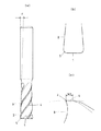
図1は先端に丸コーナ5をもつラジアスエンドミルである。図1(b)に模式図に示した丸コーナ5のコーナRは、0.2mm以上にしている。このコーナRが0.2mm以下ではコーナの強化効果が不足する。
【0027】
図1(a)の1は底刃、2は外周刃、3は溝、4は外周刃2のマージンを示す。マージン4(図1(c)参照、一点鎖線はマージンなし刃形)の幅W1は、0.02mm未満では強度が不足し、外周刃の強化効果が望めない。従って、その幅は0.02mm以上とする。このエンドミルには、丸コーナ5の外端部から溝3の後端に至る部分に、0.2°以上、3°以下のバックテーパθを付けている。
【0028】
そのバックテーパθが0.2°未満ではヘリカル加工時に切削に関与しない外周刃が仕上げ面を擦り、それによる加工面の性状悪化が起こり、工具の擦り摩耗も増加する。また、バックテーパθが3°以上では工具剛性が低下して加工中のビビリが生じやすくなる。前掲の特許文献3には、バックテーパが3°未満では側刃と仕上げ面との接触長さが長くなるため工具がビビリ易くなるとあるが(第3ページ、右下欄0011)、ヘリカル加工では工具半径方向の取り代に比べて工具軸方向の取り代(=工具が1公転する間の軸方向送り量)が小さいためワークとの接触によるビビリは発生し難い。むしろ、3°以上の方が溝3の後端部における直径が小さくなり、工具剛性が低下してビビリが生じ易くなる。
【0029】
図2は、先端のコーナ部にC0.2以上の面取り刃6を設けた面取り刃付きエンドミルである。このエンドミルも、面取り刃6の外端から溝(図示せず)の後端に至る部分の外周にバックテーパθを付けている。面取り刃6の面取り量は図1の丸コーナ5と同じ理由から0.2mm以上としている。また、バックテーパθも図1のエンドミルと同じ理由により0.2°以上、3°以下にしている。なお、このエンドミルも、バックテーパ付与部に設ける外周刃2には、0.02mm以上の幅W1を持つマージン(図1の4)をつけておくのがよい。
【0030】
図3は、ボールエンドミルのボール刃7の先端を除去し、これに代えてフラットな底刃8やすかし角を有する底刃を設けた底刃付きエンドミルであり、このエンドミルも、ボール刃7の外端から溝(図示せず)の後端に至る部分の外周にバックテーパθを付けている。このバックテーパθは図1のエンドミルと同じ理由により0.2°以上、3°以下とし、さらに、バックテーパ付与部に設ける外周刃2には、0.02mm以上の幅を持つマージン(図1の4)をつけている。
【0031】
図4は、ラジアスエンドミルの丸コーナ5(そのコーナRは0.2mm以上)の外端と、0.2°以上、3°以下のバックテーパθを付与した部分の始端aとの間にバックテーパ角が0.1°以下の図4(b)に示すストレート側刃9や、図4(c)に示す、中心Oがエンドミルの外部にある大円弧の側刃10を設けたものである。
【0032】
この側刃9(10)は、図2の面取り刃付きエンドミルや、図3の底刃付きエンドミルにも設けることができる。図3の底刃付きエンドミルに側刃9を設けた例を図5に示す。この側刃9(10)には、0.02mm以上、0.3mm以下の幅のマージン11(図4(d)参照)をつけておくのがよい。マージン幅が0.02mm未満では側刃が強度不足となり、また、0.3mmを超えると切削抵抗が増大して工がビビリ易くなる。
【0033】
ここで述べた側刃9や10を設けておくと、ヘリカル加工時に側刃がワイパー刃として働き(エンドミルが1公転する間の工具軸方向送り量が10mmを越えるとその作用は生じないが10mmを越えることはまず考えられない)、先行加工時に穴や溝の側面に付いた送りマークが次回以降の加工時に削り取られて仕上げ面の面粗度が向上する。
【0034】
なお、ここで述べた側刃9や10を有するエンドミルは、バックテーパ付与部の外周刃を省略することができる。その外周刃をつけることも勿論可能であるが、外周刃を付ける場合には、その刃の強化のために、0.02mm以上の幅のマージンを有する外周刃となすのがよい。
【0035】
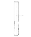
図6は、軸心部に貫通穴12を設けたエンドミルである。貫通穴12を除く構成は図1〜5に示したものと同様とする。貫通穴12を設けると、内部給油、内部給気方式にして切削油やエアを効率よく加工点に供給し、さらに、戻りの液流あるいは気流により切り屑の強制排出を行うことができ、工具摩耗、切り屑詰まりによる加工トラブルを低減できる。
【0036】
【発明の効果】
以上述べたように、この発明のエンドミルは、先端コーナが強化されているのでヘリカル加工でのコーナの欠けが減少する。また、小さ過ぎず、かつ大き過ぎないバックテーパを外周に付けて外周刃の仕上げ面への接触を防いでいるので、仕上げ面の悪化や工具の擦り摩耗が減少し、加工面の面粗度向上、工具の寿命向上の目的が達成される。
【0037】
なお、10mm以下の側刃を備えさせたものは、ヘリカル加工でワイパー効果が生じて加工された穴や溝の側面の送りマークが小さくなり、仕上げ面の面粗度が向上する。
【0038】
また、外周刃にマージンを付けたものは、外周への切り屑の噛み込みやビビリによる外周刃の欠損が減少する。
【0039】
さらに、側刃にマージンを付けたものは、工具のビビリが抑制されて加工の安定性が高まる。
【0040】
このほか、軸心部に貫通穴を設けたものは、切削油やエアを加工点に効率よく供給でき、工具寿命の向上、切り屑詰まりによる加工面の荒れの抑制、加工トラブルの抑制が図れる。
【図面の簡単な説明】
【図1】(a)この発明のエンドミルの実施形態をしめす側面図
(b)同上のエンドミルの模式図
(c)外周刃の断面図
【図2】他の実施形態の模式図
【図3】さらに他の実施形態の模式図
【図4】(a)さらに他の実施形態の模式図
(b)同上のエンドミルの先端側を拡大した模式図
(c)先端側の変形例をしめす模式図
(d)側刃の断面図
【図5】さらに他の実施形態の模式図
【図6】さらに他の実施形態の模式図
【図7】ヘリカル加工の解説図
【図8】ヘリカル加工で加工された穴や溝の側面に付く送りマークを誇張して示す図
【図9】先端コーナの除去による送りマークの減少状態を示す図
【符号の説明】
1 底刃
2 外周刃
3 溝
4、11 マージン
5 丸コーナ
6 面取り刃
7 ボール刃
8 フラットな底刃
9 ストレート側刃
10 大円弧の側刃
12 貫通穴
θ バックテーパ
M 送りマーク[0001]
TECHNICAL FIELD OF THE INVENTION
The present invention relates to an end mill with a back taper that improves machining accuracy and tool life in helical machining.
[0002]
[Prior art]
Conventional examples of end mills that perform helical machining include those disclosed in the following patent documents.
[0003]
[Patent Document 1]
Japanese Patent Publication No. 6-4205 [Patent Document 2]
JP-A-3-88620 [Patent Document 3]
Japanese Patent Application Laid-Open No. 2002-29514 [Patent Document 4]
Japanese Patent Application Laid-Open No. 2002-292515
Among these, the end mill of
[0005]
The end mill of
[0006]
The end mill of
[0007]
Furthermore, the end mill of Patent Document 4 is for cutting small-diameter contour lines, has a blade portion having an outer peripheral blade and a bottom blade, and a connecting portion between the outer peripheral blade and the bottom blade has a straight line perpendicular to the tool axis. The reverse gradient blade has an angle of 5 to 30 [deg.] With a straight line perpendicular to the tool axis in a direction opposite to the gradient toward the rotation center of the bottom blade.
[0008]
[Problems to be solved by the invention]
In the helical machining, as shown in FIG. 7, the end mill E is spirally moved while being rotated, and holes and grooves formed in the work W are dug.
[0009]
The end mill of
[0010]
The end mill of
[0011]
In the end mills of
[0012]
It is an object of the present invention to solve this problem and improve the quality of a machined surface in helical machining, and to further improve the life and the like by suppressing wear and chipping due to use.
[0013]
[Means for Solving the Problems]
In order to solve the above-mentioned problems, in the present invention, a radius end mill having a tip corner R of 0.2 mm or more, an end mill with a chamfering blade having a chamfering blade of C0.2 or more at a tip corner portion, or a ball blade ( The end mill with a flat bottom blade or a bottom blade having a bottom angle with a water mark is formed by removing the top of the spherical bottom blade and instead forming a flat bottom blade or a bottom edge with a water mark. A back taper of not less than 0.2 ° and less than 3 ° was provided at the outer end portion or a portion from the vicinity of the outer end portion to the rear end of the groove.
[0014]
The end mill of the present invention is limited to a solid or brazing type. The material of the cutting blade is not limited to a cemented carbide, an ultra-high pressure sintered body, and a high-speed steel.
[0015]
The end mill according to the present invention has a straight side blade having a length of 10 mm or less and a back taper of 0.1 ° or less between an outer end portion of the tip corner R, a C chamfering blade or a ball blade and a start end of the back taper applying portion. Alternatively, it is preferable to provide a large arc-shaped side blade whose center having a length of 10 mm or less is located outside the end mill. The side edge referred to here is an outer edge, but is referred to as a side edge to distinguish it from the outer edge of the back taper providing portion.
[0016]
In addition, an outer peripheral edge is formed in the back taper applying portion, and the outer peripheral edge is provided with a margin having a width of 0.02 mm or more, an outer peripheral edge of the back taper applying portion is omitted, and a side edge is 0.02 mm. As described above, those having a margin of 0.3 mm or less and those having a through hole for supplying a cutting fluid or air at the axis thereof can be cited as preferable embodiments.
[0017]
[Action]
In the end mill of the present invention, since the corner R, the C chamfer, or the R of the ball blade is provided, the tip corner portion is strengthened and is not easily chipped.
[0018]
Further, since the outer periphery is provided with a back taper, it is possible to prevent adverse effects due to a blade not involved in cutting during helical machining being rubbed against the finished surface, for example, deterioration of the finished surface and tool wear.
[0019]
Further, when processing is performed by feeding in the axial direction with a square end mill with a back taper, a large feed mark M remains on the side surface of the processed hole or groove, as shown in FIG. 8, and the finished surface has poor surface roughness. However, when the corner R is added to the cutting edge, the feed mark M becomes small as shown in FIG. 9, and the finished surface quality can be improved.
[0020]
A straight side blade with a length of 10 mm or less and a back taper of 0.1 ° or less, or a large arc side blade with a center of 10 mm or less located outside the end mill, has a tool axial feed amount of 10 mm or less. When the helical machining is performed under the conditions, the wiper effect by the side blade is obtained, and the feed mark is reduced, and the finished surface roughness of the side surface of the hole or groove to be machined is improved.
[0021]
In addition, in the case where a margin is provided on the outer peripheral edge of the back taper applying portion, the effect of strengthening by the margin is obtained, and an effect of preventing the outer peripheral edge from being lost due to biting of chips or so-called chatter of a tool is generated.
[0022]
In the case where the outer peripheral edge of the back taper applying portion is eliminated, there is no fear of the outer peripheral edge being damaged.
[0023]
When the side edge is provided with a margin, a guide effect is generated by the margin, so that chatter of the tool during machining is reduced, and cutting stability is enhanced.
[0024]
In addition, although machining by an end mill is usually performed by an external lubrication method, when digging a hole or a groove by helical processing, the cutting oil hardly reaches a cutting portion by external lubrication. On the other hand, those provided with through holes in the shaft center can be machined by internal lubrication, so that the lubrication and cooling of the cutting edge can be reliably performed. In addition, since chips can be forcibly discharged using the flow of the supplied oil or air, roughening of the processing surface and processing trouble due to chip clogging are reduced.
[0025]
BEST MODE FOR CARRYING OUT THE INVENTION
Hereinafter, an embodiment of an end mill of the present invention will be described with reference to the accompanying drawings. In addition, all end mills other than FIG. 1 are shown in a schematic diagram.
[0026]
FIG. 1 shows a radius end mill having a
[0027]
In FIG. 1A, 1 is a bottom blade, 2 is an outer peripheral blade, 3 is a groove, and 4 is a margin of the outer
[0028]
If the back taper θ is less than 0.2 °, the outer peripheral edge that is not involved in cutting during helical machining rubs the finished surface, thereby deteriorating the properties of the machined surface and increasing the rubbing wear of the tool. If the back taper θ is 3 ° or more, the tool rigidity decreases, and chatter during machining is likely to occur. According to
[0029]
FIG. 2 shows an end mill with a chamfered blade provided with a chamfered blade 6 of C0.2 or more at a corner portion at the tip. This end mill also has a back taper .theta. On the outer periphery of a portion from the outer end of the chamfering blade 6 to the rear end of a groove (not shown). The chamfering amount of the chamfering blade 6 is set to 0.2 mm or more for the same reason as the
[0030]
FIG. 3 shows an end mill with a bottom blade in which the tip of the
[0031]
FIG. 4 shows the back end between the outer end of the
[0032]
The side blade 9 (10) can be provided in the end mill with a chamfered blade in FIG. 2 and the end mill with a bottom blade in FIG. FIG. 5 shows an example in which the
[0033]
If the
[0034]
In the end mill having the
[0035]
FIG. 6 shows an end mill in which a through
[0036]
【The invention's effect】
As described above, in the end mill of the present invention, since the tip corner is strengthened, chipping of the corner in helical machining is reduced. A back taper that is not too small and not too large is attached to the outer circumference to prevent the outer blade from contacting the finished surface, which reduces the deterioration of the finished surface and the abrasion of the tool, and reduces the surface roughness of the machined surface. The purpose of improvement and tool life improvement is achieved.
[0037]
In the case of having a side blade of 10 mm or less, the feed mark on the side surface of the hole or groove processed by the helical processing due to the wiper effect is reduced, and the surface roughness of the finished surface is improved.
[0038]
In addition, when the outer peripheral edge is provided with a margin, chipping of the outer peripheral edge and loss of the outer peripheral edge due to chatter are reduced.
[0039]
Further, with the side edge having a margin, the chatter of the tool is suppressed, and the stability of machining is improved.
[0040]
In addition, those with a through hole in the shaft center can efficiently supply cutting oil and air to the processing point, improve tool life, suppress roughening of the processing surface due to clogging of chips, and suppress processing trouble. .
[Brief description of the drawings]
1A is a side view showing an embodiment of an end mill of the present invention. FIG. 1B is a schematic view of the end mill of the embodiment. FIG. 1C is a sectional view of an outer peripheral blade. FIG. 2 is a schematic view of another embodiment. FIG. 4 (a) is a schematic view of still another embodiment, FIG. 4 (b) is a schematic view of the end mill of the same embodiment, and FIG. 4 (c) is an enlarged schematic view of the end side of the end mill. d) Cross-sectional view of the side blade [Fig. 5] Schematic diagram of still another embodiment [Fig. 6] Schematic diagram of still another embodiment [Fig. 7] Explanatory diagram of helical machining [Fig. 8] Processed by helical machining Diagram showing exaggerated feed marks attached to the side surfaces of holes and grooves [FIG. 9] Diagram showing the reduced number of feed marks due to removal of tip corners [Description of reference numerals]
DESCRIPTION OF
Claims (6)
Priority Applications (1)
| Application Number | Priority Date | Filing Date | Title |
|---|---|---|---|
| JP2002379233A JP2004209559A (en) | 2002-12-27 | 2002-12-27 | End mill with back taper |
Applications Claiming Priority (1)
| Application Number | Priority Date | Filing Date | Title |
|---|---|---|---|
| JP2002379233A JP2004209559A (en) | 2002-12-27 | 2002-12-27 | End mill with back taper |
Publications (1)
| Publication Number | Publication Date |
|---|---|
| JP2004209559A true JP2004209559A (en) | 2004-07-29 |
Family
ID=32815791
Family Applications (1)
| Application Number | Title | Priority Date | Filing Date |
|---|---|---|---|
| JP2002379233A Pending JP2004209559A (en) | 2002-12-27 | 2002-12-27 | End mill with back taper |
Country Status (1)
| Country | Link |
|---|---|
| JP (1) | JP2004209559A (en) |
Cited By (18)
| Publication number | Priority date | Publication date | Assignee | Title |
|---|---|---|---|---|
| JP2006247774A (en) * | 2005-03-09 | 2006-09-21 | Mitsubishi Materials Corp | End mill |
| WO2007013447A1 (en) * | 2005-07-25 | 2007-02-01 | Mitsubishi Materials Corporation | Radius end mill and cutting method |
| KR100720745B1 (en) * | 2006-01-26 | 2007-05-23 | 이 트라운 엔터프라이즈 컴퍼니 리미티드 | Milling cutter |
| JP2007290105A (en) * | 2006-04-27 | 2007-11-08 | Tungaloy Corp | End mill |
| JP2008049450A (en) * | 2006-08-25 | 2008-03-06 | Osg Corp | Standing-wall machining method and end mill for machining standing-wall |
| JP2008537909A (en) * | 2005-03-31 | 2008-10-02 | ハニタ・メタル・ワークス・リミテッド | Track end mill |
| WO2008132859A1 (en) | 2007-04-23 | 2008-11-06 | Union Tool Co. | Rotary cutting tool |
| JP2009056587A (en) * | 2007-08-30 | 2009-03-19 | Snecma | Grooving milling cutter for machining with high feed and low cutting depth |
| JP2009532222A (en) * | 2006-04-04 | 2009-09-10 | ハニタ・メタル・ワークス・リミテッド | Face milling |
| KR101139119B1 (en) * | 2006-04-02 | 2012-04-30 | 이스카 엘티디. | End mill |
| CN104191008A (en) * | 2014-07-30 | 2014-12-10 | 常州创伟工具制造有限公司 | Chamfering cutter |
| JP2017159389A (en) * | 2016-03-08 | 2017-09-14 | トーヨーエイテック株式会社 | Drilling method using end mill |
| WO2018025349A1 (en) * | 2016-08-03 | 2018-02-08 | 株式会社Opmラボラトリー | Cutting tool and apparatus for producing three-dimensional additive manufacturing product |
| CN107824854A (en) * | 2017-12-11 | 2018-03-23 | 成都飞机工业(集团)有限责任公司 | A kind of new anti-mistake cuts milling cutter |
| JP2020146827A (en) * | 2019-03-06 | 2020-09-17 | 住友化学株式会社 | Manufacturing method of machined laminated film |
| CN111975074A (en) * | 2020-09-10 | 2020-11-24 | 西安昂达机电科技有限公司 | End milling cutter for machining side wall |
| JP2023137858A (en) * | 2022-03-18 | 2023-09-29 | ユニオンツール株式会社 | ball end mill |
| US11865629B2 (en) | 2021-11-04 | 2024-01-09 | Kennametal Inc. | Rotary cutting tool with high ramp angle capability |
Citations (12)
| Publication number | Priority date | Publication date | Assignee | Title |
|---|---|---|---|---|
| JPS52120487A (en) * | 1976-04-02 | 1977-10-08 | Kobe Steel Ltd | Rough cutting miller |
| JPS61163115U (en) * | 1985-03-30 | 1986-10-09 | ||
| JPH01316110A (en) * | 1988-06-13 | 1989-12-21 | Sumitomo Electric Ind Ltd | Drilling method |
| JPH02106211A (en) * | 1988-10-13 | 1990-04-18 | Toshiba Tungaloy Co Ltd | Finishing end mill |
| JPH10230407A (en) * | 1997-02-18 | 1998-09-02 | Shinko Kobelco Tool Kk | End mill |
| JPH11254231A (en) * | 1998-03-12 | 1999-09-21 | Sumikin Stainless Kokan Kk | Chamfering device for end surface circumferential corner part of workpiece |
| JP2000000716A (en) * | 1998-06-15 | 2000-01-07 | Osg Corp | End mill |
| JP2000190120A (en) * | 1998-12-28 | 2000-07-11 | Hitachi Tool Engineering Ltd | High helix end mill |
| JP2002046008A (en) * | 2000-08-03 | 2002-02-12 | Tsutsui Seiken:Kk | Cutting tool |
| JP2002052415A (en) * | 2000-05-30 | 2002-02-19 | Mitsubishi Materials Corp | Indexable inserts and indexable cutting tools |
| JP2002292514A (en) * | 2001-03-30 | 2002-10-08 | Hitachi Tool Engineering Ltd | End mill of small diameter for cutting contour line |
| JP2002292515A (en) * | 2001-03-29 | 2002-10-08 | Hitachi Tool Engineering Ltd | End mill for cutting contour line |
-
2002
- 2002-12-27 JP JP2002379233A patent/JP2004209559A/en active Pending
Patent Citations (12)
| Publication number | Priority date | Publication date | Assignee | Title |
|---|---|---|---|---|
| JPS52120487A (en) * | 1976-04-02 | 1977-10-08 | Kobe Steel Ltd | Rough cutting miller |
| JPS61163115U (en) * | 1985-03-30 | 1986-10-09 | ||
| JPH01316110A (en) * | 1988-06-13 | 1989-12-21 | Sumitomo Electric Ind Ltd | Drilling method |
| JPH02106211A (en) * | 1988-10-13 | 1990-04-18 | Toshiba Tungaloy Co Ltd | Finishing end mill |
| JPH10230407A (en) * | 1997-02-18 | 1998-09-02 | Shinko Kobelco Tool Kk | End mill |
| JPH11254231A (en) * | 1998-03-12 | 1999-09-21 | Sumikin Stainless Kokan Kk | Chamfering device for end surface circumferential corner part of workpiece |
| JP2000000716A (en) * | 1998-06-15 | 2000-01-07 | Osg Corp | End mill |
| JP2000190120A (en) * | 1998-12-28 | 2000-07-11 | Hitachi Tool Engineering Ltd | High helix end mill |
| JP2002052415A (en) * | 2000-05-30 | 2002-02-19 | Mitsubishi Materials Corp | Indexable inserts and indexable cutting tools |
| JP2002046008A (en) * | 2000-08-03 | 2002-02-12 | Tsutsui Seiken:Kk | Cutting tool |
| JP2002292515A (en) * | 2001-03-29 | 2002-10-08 | Hitachi Tool Engineering Ltd | End mill for cutting contour line |
| JP2002292514A (en) * | 2001-03-30 | 2002-10-08 | Hitachi Tool Engineering Ltd | End mill of small diameter for cutting contour line |
Cited By (26)
| Publication number | Priority date | Publication date | Assignee | Title |
|---|---|---|---|---|
| JP2006247774A (en) * | 2005-03-09 | 2006-09-21 | Mitsubishi Materials Corp | End mill |
| JP2008537909A (en) * | 2005-03-31 | 2008-10-02 | ハニタ・メタル・ワークス・リミテッド | Track end mill |
| WO2007013447A1 (en) * | 2005-07-25 | 2007-02-01 | Mitsubishi Materials Corporation | Radius end mill and cutting method |
| JP2007030074A (en) * | 2005-07-25 | 2007-02-08 | Mitsubishi Materials Kobe Tools Corp | Radius end mill and cutting method |
| KR101351727B1 (en) * | 2005-07-25 | 2014-01-14 | 미쓰비시 마테리알 가부시키가이샤 | Radius end mill and cutting method |
| US7997834B2 (en) | 2005-07-25 | 2011-08-16 | Mitsubishi Materials Corporation | Radius end mill and cutting method |
| KR100720745B1 (en) * | 2006-01-26 | 2007-05-23 | 이 트라운 엔터프라이즈 컴퍼니 리미티드 | Milling cutter |
| KR101139119B1 (en) * | 2006-04-02 | 2012-04-30 | 이스카 엘티디. | End mill |
| JP2009532222A (en) * | 2006-04-04 | 2009-09-10 | ハニタ・メタル・ワークス・リミテッド | Face milling |
| JP2007290105A (en) * | 2006-04-27 | 2007-11-08 | Tungaloy Corp | End mill |
| JP2008049450A (en) * | 2006-08-25 | 2008-03-06 | Osg Corp | Standing-wall machining method and end mill for machining standing-wall |
| US8186914B2 (en) | 2007-04-23 | 2012-05-29 | Union Tool Co. | Rotary cutting tool |
| WO2008132859A1 (en) | 2007-04-23 | 2008-11-06 | Union Tool Co. | Rotary cutting tool |
| JP2009056587A (en) * | 2007-08-30 | 2009-03-19 | Snecma | Grooving milling cutter for machining with high feed and low cutting depth |
| CN104191008A (en) * | 2014-07-30 | 2014-12-10 | 常州创伟工具制造有限公司 | Chamfering cutter |
| JP2017159389A (en) * | 2016-03-08 | 2017-09-14 | トーヨーエイテック株式会社 | Drilling method using end mill |
| JPWO2018025349A1 (en) * | 2016-08-03 | 2018-08-02 | 株式会社Opmラボラトリー | Cutting tool and 3D additive manufacturing apparatus |
| WO2018025349A1 (en) * | 2016-08-03 | 2018-02-08 | 株式会社Opmラボラトリー | Cutting tool and apparatus for producing three-dimensional additive manufacturing product |
| CN107824854A (en) * | 2017-12-11 | 2018-03-23 | 成都飞机工业(集团)有限责任公司 | A kind of new anti-mistake cuts milling cutter |
| JP2020146827A (en) * | 2019-03-06 | 2020-09-17 | 住友化学株式会社 | Manufacturing method of machined laminated film |
| JP7386674B2 (en) | 2019-03-06 | 2023-11-27 | 住友化学株式会社 | Manufacturing method of cut laminated film |
| TWI858026B (en) * | 2019-03-06 | 2024-10-11 | 日商住友化學股份有限公司 | Method for producing cutting-processed laminated film |
| CN111975074A (en) * | 2020-09-10 | 2020-11-24 | 西安昂达机电科技有限公司 | End milling cutter for machining side wall |
| US11865629B2 (en) | 2021-11-04 | 2024-01-09 | Kennametal Inc. | Rotary cutting tool with high ramp angle capability |
| JP2023137858A (en) * | 2022-03-18 | 2023-09-29 | ユニオンツール株式会社 | ball end mill |
| JP7516447B2 (en) | 2022-03-18 | 2024-07-16 | ユニオンツール株式会社 | Ball End Mill |
Similar Documents
| Publication | Publication Date | Title |
|---|---|---|
| JP2004209559A (en) | End mill with back taper | |
| KR101528936B1 (en) | Drill body | |
| KR101348459B1 (en) | Cutting tool and cutting insert | |
| KR101516826B1 (en) | Insert for drill and insert drill | |
| KR101351727B1 (en) | Radius end mill and cutting method | |
| TWI577472B (en) | Rotary milling tool | |
| JP4809306B2 (en) | Ball end mill | |
| KR102399372B1 (en) | drill | |
| KR101351128B1 (en) | End mill | |
| JP2010105093A (en) | Ball end mill | |
| JP6268809B2 (en) | drill | |
| JP2008254089A (en) | Deep hole cutting equipment | |
| JPWO2008001412A1 (en) | Drill | |
| CN113226606B (en) | Rotary tools with coolant holes | |
| WO2019188135A1 (en) | End mill main body and end mill | |
| JP2015226953A (en) | Small diameter end mill | |
| JP2023068305A (en) | Drill | |
| JP4431164B2 (en) | Inner diameter machining tool | |
| JP2005319544A (en) | Hole machining tool, and method of grinding outer periphery of the tool | |
| JPH0524218U (en) | Drilling tool | |
| JP2002301613A (en) | Drill with diamond sintered body | |
| JP2006326752A (en) | Drill | |
| JP5052399B2 (en) | Internal thread processing method | |
| JP2008142870A (en) | Cutting tool | |
| JP2005305618A (en) | Edge replaceable rotary tool |
Legal Events
| Date | Code | Title | Description |
|---|---|---|---|
| A711 | Notification of change in applicant |
Free format text: JAPANESE INTERMEDIATE CODE: A712 Effective date: 20060308 |
|
| A977 | Report on retrieval |
Free format text: JAPANESE INTERMEDIATE CODE: A971007 Effective date: 20060313 |
|
| A131 | Notification of reasons for refusal |
Free format text: JAPANESE INTERMEDIATE CODE: A131 Effective date: 20060425 |
|
| A521 | Written amendment |
Free format text: JAPANESE INTERMEDIATE CODE: A523 Effective date: 20060622 |
|
| A131 | Notification of reasons for refusal |
Free format text: JAPANESE INTERMEDIATE CODE: A131 Effective date: 20061010 |
|
| A02 | Decision of refusal |
Free format text: JAPANESE INTERMEDIATE CODE: A02 Effective date: 20070605 |