JP2004222003A - Image forming system and image forming apparatus - Google Patents
Image forming system and image forming apparatus Download PDFInfo
- Publication number
- JP2004222003A JP2004222003A JP2003007677A JP2003007677A JP2004222003A JP 2004222003 A JP2004222003 A JP 2004222003A JP 2003007677 A JP2003007677 A JP 2003007677A JP 2003007677 A JP2003007677 A JP 2003007677A JP 2004222003 A JP2004222003 A JP 2004222003A
- Authority
- JP
- Japan
- Prior art keywords
- job
- image
- image forming
- unit
- print job
- Prior art date
- Legal status (The legal status is an assumption and is not a legal conclusion. Google has not performed a legal analysis and makes no representation as to the accuracy of the status listed.)
- Pending
Links
Images


Landscapes
- Accessory Devices And Overall Control Thereof (AREA)
- Facsimiles In General (AREA)
Abstract
Description
【0001】
【発明の属する技術分野】
本発明は、電気的に接続可能な複数の画像形成装置を用いることにより、印刷機能を分担して連結印刷を可能とする画像形成システム及び画像形成装置に関する。
【0002】
【従来の技術】
従来からジョブ実行中に読み取りユニットや画像メモリが利用可能な状態で、ジョブを予約可能な画像形成装置が考えられている。一方、複数台のデジタル複写機を機能的に連結して使用する技術が知られている。親機側で連結モードを選択し、読み取った画像を連結されている子機とで分担し、印刷動作を並行して行わせることによってパフォーマンスの向上を得ている。たとえば、1枚の原稿を100枚コピーする際、連結状態にある画像形成装置が2台ある場合は1台あたり50枚ずつ印刷動作を行うことにより印刷時間を短縮することができる。
【0003】
従来技術例として、ジョブ予約と順序入れ替え機能を有する「画像形成装置、情報処理システム、画像形成方法及び記憶媒体」がある(例えば、特許文献1参照)。また、ジョブ予約機能を有する「画像形成装置」がある(例えば、特許文献2参照)。
【0004】
【特許文献1】
特開2000−47530号公報
【特許文献2】
特開平11−88570号公報
【0005】
【発明が解決しようとする課題】
しかしながら、上記従来の画像形成装置の連結機能とジョブの予約機能とを有するシステムにおいて、親機のジョブの予約時に子機のジョブを同時に予約した場合、親機の連結ジョブが完了するまで、以後の子機単独ジョブの実行が妨げられてしまったり、予約順序の入れ替え結果によっては双方の予約ジョブの実行がお互いに妨げられる結果になってしまったりする。
【0006】
本発明は上記問題に対して鑑みてなされたものであり、子機側が連結ジョブを実行する順番が来たときにジョブの予約(エントリ)を行うようにして、子機側の効率よい稼働と予約ジョブの入れ替えによる双方デッドロックを回避し、効率良く連結ジョブを制御する画像形成システム及び画像形成装置を提供することを目的としている。
【0007】
また、本発明は、子機側のジョブの最後ではなく、印刷中ジョブの最後にエントリすることによって、優先的に連結ジョブを動作させる画像形成システム及び画像形成装置を提供することを目的としている。
【0008】
また、本発明は、子機側の単独ジョブを優先するか、連結子機ジョブを優先するかを選択設定可能にして、ユーザの利用環境に合わせることを可能とし、また、設定情報を不揮発メモリに保持することにより、主電源投入時に再設定する必要を無くす画像形成システム及び画像形成装置を提供することを目的としている。
【0009】
【課題を解決するための手段】
かかる目的を達成するために、請求項1記載の画像形成システムは、画像の入力を行う画像入力手段と、画像入力手段にて入力された画像を記憶する第1の記憶手段と、第1の記憶手段から画像データを読み出して画像形成する第1の画像形成手段と、第1の記憶手段に保持されている画像データを他の画像形成装置に転送するための画像データ転送手段と、他の画像形成装置間でコマンドデータを送受信するコマンドデータ送受信手段と、上記各手段を制御する第1の制御手段とを有する第1の画像形成装置と、第1の画像形成装置から画像データ転送手段で送られた画像データを記憶する第2の記憶手段と、コマンドデータ送受信手段で受け取った要求に従って第2の記憶手段から画像データを読み出して画像形成する第2の画像形成手段と、上記各手段を制御する第2の制御手段とを有する複数の画像形成装置とが接続された連結画像形成システムであって、画像形成処理のジョブを、読み取りジョブと印刷ジョブとの組み合わせで管理するジョブ管理手段と、第1の印刷ジョブが稼働中に、第2の印刷単独ジョブを予約する、あるいは第1の印刷ジョブが稼働中に、第2のジョブの読み取りジョブを先行動作させ、第2の印刷ジョブを予約するジョブ予約手段と、投入されたジョブ順に画像形成する順序管理手段とを有し、第2の画像形成装置の印刷ジョブを順序登録する時期を、第1の画像形成装置の印刷ジョブ開始に同期させることを特徴としている。
【0010】
請求項2記載の画像形成システムは、請求項1記載の画像形成システムにおいて、第2の画像形成装置に順序登録される印刷ジョブは、第2の画像形成装置で印刷中のジョブとその後に予約されたジョブが存在する場合、印刷中のジョブの次に挿入予約されることを特徴としている。
【0011】
請求項3記載の画像形成システムは、請求項2記載の画像形成システムにおいて、第2の画像形成装置に順序登録される印刷ジョブを、印刷中のジョブの直後に挿入予約するか、全予約ジョブの最後に予約するか、選択する選択手段を有することを特徴としている。
【0012】
請求項4記載の画像形成システムは、請求項3記載の画像形成システムにおいて、設定情報を保持する不揮発メモリを有し、選択状態を不揮発メモリに保持することを特徴としている。
【0013】
請求項5記載の画像形成装置は、画像の入力を行う画像入力手段と、画像入力手段で入力された画像を記憶する入力画像記憶手段と、入力画像記憶手段から画像データを読み出して画像形成する第1の画像形成手段と、入力画像記憶手段に保持されている画像データを他の画像形成装置に転送するための画像データ転送手段と、他の画像形成装置とコマンドデータを送受信するコマンドデータ送受信手段と、他の画像形成装置から送信された画像データを記憶する送信画像データ記憶手段と、コマンドデータ送受信手段で受け取った要求に従って送信画像データ記憶手段から画像データを読み出して画像形成する第2の画像形成手段と、上記各手段を制御する制御手段と、画像形成処理のジョブを、読み取りジョブと印刷ジョブとの組み合わせで管理するジョブ管理手段と、第1の印刷ジョブが稼働中に、第2の印刷単独ジョブを予約する、あるいは第2の印刷ジョブの読み取りジョブを先行動作させ、前記第2の印刷ジョブを予約するジョブ予約手段と、投入されたジョブ順に画像形成する順序管理手段とを有することを特徴としている。
【0014】
【発明の実施の形態】
以下、本発明の実施の形態について、添付図面を参照にしながら詳細に説明する。
【0015】
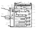
図1に本発明の画像形成装置を示す。自動原稿送り装置(以後ADF)1にある、原稿台2に原稿の画像面を上にして置かれた原稿束は、操作部30上のスタートキー34が押下されると、一番上の原稿から給送ローラ3、給送ベルト4によってコンタクトガラス6上の所定の位置に給送される。読み取りユニット50によってコンタクトガラス6上の原稿の画像データを読み取り後、読み取りが終了した原稿は、給送ベルト4及び排送ローラ5によって排出される。さらに、原稿セット検知7にて原稿台2に次の原稿が有ることを検知した場合、前原稿と同様にコンタクトガラス6上に給送される。給送ローラ3、給送ベルト4、排送ローラ5はモータによって駆動される。
【0016】
第1トレイ8、第2トレイ9、第3トレイ10に積載された転写紙は、各々第1給紙装置11、第2給紙装置12、第3給紙装置13によって給紙され、縦搬送ユニット14によって感光体15に当接する位置まで搬送される。読み取りユニット50にて読み込まれた画像データは、書き込みユニット57からのレーザによって感光体15に書き込まれ、現像ユニット27を通過することによってトナー像が形成される。そして、転写紙は感光体15の回転と等速で搬送ベルト16によって搬送されながら、感光体15上のトナー像が転写される。その後、定着ユニット17にて画像を定着させ、排紙ユニット18によって後処理装置のフィニシャ100に排出される。
【0017】
後処理装置のフィニシャ100は、通常排紙ローラ102方向と、ステープル処理部方向に導く事ができる。切り替え板101を上に切り替える事により、搬送ローラ103を経由して通常排紙トレイ104側に排紙する事ができる。また、切り替え板101を下方向に切り替える事で、搬送ローラ105、107を経由して、ステープル台108に搬送する事ができる。
【0018】
ステープル台108に積載された転写紙は、一枚排紙去れるごとに紙揃え用のジョガー109によって、紙端面が揃えられ、一部のコピー完了と共にステープラ106によって綴じられる。ステープラ106で綴じられた転写紙群は自重によって、ステープル完了排紙トレイ110に収納される。
【0019】
一方、通常の排紙トレイ104は前後に移動可能な排紙トレイである。前後に移動可能な排紙トレイ部104は、原稿毎、あるいは、画像メモリによってソーティングされたコピー部毎に、前後に移動し、簡易的に排出されてくるコピー紙を仕分けるものである。
【0020】
転写紙の両面に画像を作像する場合は、各給紙トレイ8〜10から給紙され作像された転写紙を排紙トレイ104側に導かないで、経路切り替えの為の分岐爪112を上側にセットする事で、一旦両面給紙ユニット111にストックする。
【0021】
その後、両面給紙ユニット111にストックされた転写紙は再び感光体15に作像されたトナー画像を転写するために、両面給紙ユニット111から再給紙され、経路切り替えの為の分岐爪112を下側にセットし、排紙トレイ104に導く。この様に転写紙の両面に画像を作成する場合に両面給紙ユニット111は使用される。
【0022】
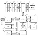
次に、図4に示すように、本実施形態で用いる画像形成装置の各構成部である、感光体15、搬送ベルト16、定着ユニット17、排紙ユニット18、現像ユニット27は、メインモータ25によって駆動される。メインコントローラ20は、前記各ユニットをプログラムに従って制御する。図1の各給紙装置11〜13はメインモータ25の駆動を各々給紙クラッチ22〜24によって伝達駆動される。縦搬送ユニット14はメインモータ25の駆動を中間クラッチ21によって伝達駆動される。
【0023】
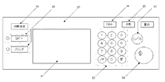
図2は、操作部30を示した図である。操作部30には、液晶タッチパネル31、テンキー32、クリア/ストップキー33、プリントキー34、予熱キー35、リセットキー36があり、液晶タッチパネル31には、後述するモード設定のためのキーや画像形成装置の状態を示すメッセージなどが表示される。
【0024】
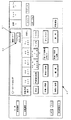
図3は操作部30の液晶タッチパネル31の表示一例を示した図である。オペレータが液晶タッチパネル31に表示されたキーにタッチする事で、選択された機能を示すキーが黒く反転する。また、機能の詳細を指定しなければならない場合(例えば変倍であれは変倍値等)は、キーにタッチする事で、詳細機能の設定画面が表示される。このように、液晶タッチパネルは、ドット表示器を使用している為、その時の最適な表示をグラフィカルに行う事が可能である。
【0025】
図3において左上は、「コピーできます」、「お待ちください」等のメッセージを表示するメッセージエリア、その右は、セットした枚数を表示するコピー枚数表示部、転写紙を自動的に選択する自動用紙選択キー、コピーを一部ずつページ順にそろえる処理を指定するソートキー、コピーをページ毎に仕分けする処理を指定するスタックキー、ソート処理されたものを一部ずつ綴じる処理を指定するステープルキー、倍率を等倍にセットする等倍キー、拡大/縮小倍率をセットする変倍キー、両面モードを設定する両面キー、とじ代モード等を設定する編集キー、表紙/合紙モードを設定する表紙/合紙キー、デジタル複写機のネットワークを介して多量のプリント動作を複数に分けてプリントアウトする連結モードキーである。
【0026】
また、給紙トレイ数に対応した給紙トレイ状態を示し、手動で給紙段を設定するためのキーが給紙段分表示されている。
【0027】
図1を用いて、本発明における画像読み取り手段、および画像を記録面上に潜像形成するまでの動作を説明する。潜像とは感光体面上に画像を光情報に変換して照射することにより生じる電位分布である。
【0028】
読み取りユニット50は、原稿を載置するコンタクトガラス6と光学走査系で構成されており、光学走査系には、露光ランプ51、第1ミラー52、レンズ53、CCDイメージセンサ54等々で構成されている。露光ランプ51及び第1ミラー52は図示しない第1キャリッジ上に固定され、第2ミラー55及び第3ミラー56は図示しない第2キャリッジ上に固定されている。原稿像を読み取るときには、光路長が変わらないように、第1キャリッジと第2キャリッジとが2対1の相対速度で機械的に走査される。この光学走査系は、図示しないスキャナ駆動モータにて駆動される。原稿画像は、CCDイメージセンサ54によって読み取られ、電気信号に変換されて処理される。レンズ53及びCCDイメージセンサ54を第1図において左右方向に移動させることにより、画像倍率が変わる。すなわち、指定された倍率に対応してレンズ53及びCCDイメージセンサ54の左右方向に位置が設定される。
【0029】
書き込みユニット57はレーザ出力ユニット58、結像レンズ59、ミラー60で構成され、レーザ出力ユニット58の内部には、レーザ光源であるレーザダイオード及びモータによって高速で定速回転する回転多面鏡(ポリゴンミラー)が備わっている。
【0030】
レーザ出力ユニット58より照射されるレーザ光は、定速回転するポリゴンミラーで偏光され、結像レンズ59を通り、ミラー60で折り返され、感光体面上に集光結像する。
【0031】
偏光されたレーザ光は感光体が回転する方向と直行する方向(主走査方向)に露光走査され、後述する画像処理部のセレクタ64より出力された画像信号のライン単位の記録を行う。感光体の回転速度と記録密度に対応した所定の周期で主走査を繰り返すことによって、感光体面上に画像(静電潜像)が形成される。
【0032】
上述のように、書き込みユニット57から出力されるレーザ光が、画像作像系の感光体15に照射される。図示しないが感光体15の一端近傍のレーザビームを照射される位置に、主走査同期信号を発生するビームセンサが配置されている。この主走査同期信号をもとに主走査方向の画像記録開始タイミングの制御、および後述する画像信号の入出力を行うための制御信号の生成を行う。
【0033】
本実施例における画像処理部(画像読み取り部と画像書き込み部)の構成について、図5を用いて説明する。露光ランプ51から照射された光は原稿面を照射し、原稿面からの反射光を、CCDイメージセンサ54にて結像レンズ(図示せず)により結像、受光して光電変換し、A/Dコンバータ61にてデジタル信号に変換する。デジタル信号に変換された画像信号は、シェーディング補正62がなされた後、画像処理部63にてMTF補正、γ補正等がなされる。セレクタ64では、画像信号の送り先を、書き込みγ補正部71または、画像メモリコントローラ65への切り替えが行われる。書き込みγ補正部71を経由した画像信号は書き込みユニット57に送られる。画像メモリコントローラ65とセレクタ64間は、双方向に画像信号を入出力可能な構成となっている。図5には特に明示していないが、画像処理部(IPU)には、読み取り部50から入力される画像データ以外にも外部から供給される画像データ(例えばパーソナルコンピュータ等のデータ処理装置から出力されるデータ)も処理できるよう、複数のデータの入出力の選択を行う機能を有している。
【0034】
画像メモリコントローラ65等への設定や、読み取り部50書き込み部57の制御を行うCPU68、及びそのプログラムやデータを格納するROM69、RAM70を備えている。更にCPU68は、メモリコントローラ65を介して、画像メモリ66のデータの書き込み、読み出しが行える。また画像メモリ66の内容を退避させたり、保存したりするためのHDD71を備えている。
【0035】
ここで、図6を用いて、セレクタ64における1ページ分の画像信号について説明する。
【0036】
/FGATEは、1ページの画像データの副走査方向の有効期間を表している。/LSYNCは、1ライン毎の主走査同期信号であり、この信号が立ち上がった後の所定クロックで、画像信号が有効となる。主走査方向の画像信号が有効であることを示す信号が、/LGATEである。これらの信号は、画素クロックVCLKに同期しており、VCLKの1周期に対し1画素のデータが送られてくる。画像処理部(IPU)49は、画像入力、出力それぞれに対して別個の/FGATE、/LSYNC、/LGATE、VCLKの発生機構を有しており、様々な画像入出力の組み合わせが実現可能になる。
【0037】
また、作業分担するために他のデジタル複写機と画像データやコマンドの送受信を行う必要があるが、これは、この実施例では画像データの送受信用にIEEE1394の連結インタフェースを、コマンドの送受信用にシリアル通信ラインを用いている。図5のメモリコントローラが連結インターフェースドライバ80を介してそれを実現している。
【0038】
次に、本画像形成装置内のソフトウェア制御モジュール構成と、画像転送、印刷制御について説明する。図7は、ソフトウェアのモジュール構成を示した図である。
【0039】
アプリケーション層で設定されたジョブ情報は、スタートキーなどをトリガーにコントロールサービス層に受け渡される。コントロールサービス層は、アプリからのジョブ情報を解釈し、ハンドラ層を動作させるためのプロセス情報をハンドラマネージャに要求する。ハンドラマネージャは、プロセス情報に従って個々のハンドラを動作させる。ハンドラには、読み取りユニットを制御するスキャナハンドラ、画像メモリへの画像データの入出力を制御する画像メモリハンドラ、書き込みユニットと用紙搬送、後処理周辺機を制御するプロッタハンドラが有り、これらのソフトウェアモジュールが連携して、読み取りから画像メモリへの蓄積と画像形成の処理が行われる。
【0040】
さらに本画像形成装置には、他の画像形成装置と連結するための、連結I/Fドライバを備え、このI/Fを介して画像データとコマンド情報の受け渡しが可能になっている。
【0041】
単体コピージョブでは、画像の読み取りと蓄積、蓄積画像の印刷という手順で行われるが、連結コピージョブでは、前記手順に加え以下の制御が加わる。
【0042】
親機側で発生した連結コピージョブは、親機のコントロールサービス内でジョブ情報が解釈された後、スキャナで読み取った画像を画像メモリに蓄積するプロセスと、その画像を子機の画像メモリに転送するプロセスに分けてそれぞれ実行される。
【0043】
必要な画像の転送が完了すると、子機のコントロールサービスは、親機のコントロールサービスから受け取った情報に従って、予め転送されている画像データを参照する印刷プロセスを生成し、子機のハンドラマネージャに印刷を要求する。
【0044】
そして子機のコントロールサービスは、親機に対して自機で処理した印刷ジョブを親機に逐次通知する。この情報に従って親機のコントロールサービスは、自機の印刷ジョブと子機側の印刷ジョブの経過を監視し、必要分の印刷を行う。
【0045】
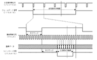
図8以降を用いて本発明の詳細を説明する。まず連結コピージョブを行うにあたっては、前述の説明の通り、親機では、読み取りジョブの実行と画像データの蓄積、親機印刷ジョブのエントリ(予約)と実行に分類され、親機から子機へは、画像データの転送と子機印刷ジョブのエントリ(予約)と実行という手続きに分けられる。そして、親機側が全印刷ジョブの分配制御を司るために、子機の印刷ジョブはすくなくとも親機の印刷ジョブ開始以降に実行される。これらを視覚化した図が、図8、図9である。なお、本発明による連結画像形成システムで、どの装置も親機としてコピージョブを実行することが可能である。
【0046】
図8、図9は、親機単独ジョブJOB11、JOB12の順でコピージョブを予約・実行し、連結コピージョブJOB13が予約された際の遷移について横軸を時間に見立てた図である。子機では、子機単独コピージョブJOB21、22、23が予約、実行されている。
【0047】
まず、従来の連結コピージョブの制御(図8)においては、読み取りジョブ開始に同期して親機と子機の印刷ジョブをエントリしていた(200)。一方、本発明の連結コピージョブの制御(図9)においては、親機の印刷ジョブの開始に同期して子機の印刷ジョブをエントリする(203)。
【0048】
従来の制御(図8)では、子機の連結ジョブはJOB22の後になるため、親機のJOB13が開始される迄待ち時間201を生じる事がある。一方、本発明の制御(図9)では、親機の印刷ジョブJOB13に同期して子機の印刷ジョブがエントリされるので、子機の連結ジョブは230のJOB23の後にエントリされる。ちなみに、202、203は、連結コピージョブの親子間の再分配量を指している。
【0049】
このような連結コピージョブ制御を行うことによって、全ジョブの完了に要する時間を207に示す分短縮できる。
【0050】
次に、図10から図13を用いて、子機の連結ジョブを後端にエントリする制御と、印刷中ジョブの直後に挿入する制御について説明する。
【0051】
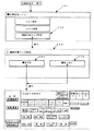
図10は、子機の連結印刷ジョブを優先するかしないかを設定する画面フローである。操作パネル30上の初期設定キー39を押下することにより、各種初期設定を行う画面251に遷移する。ここで「連結子機ジョブ設定」キー252を押下すると、設定画面253が表示される。この設定画面内で「優先する」キー254を押下すると、印刷中のジョブの直後にエントリ(予約)するモードが設定される。「優先しない」キー255が押下されると、全印刷ジョブの最後にエントリ(予約)するモードが設定される。そしてこの設定は、不揮発メモリに書き込まれ、次の電源再投入時にも有効になる。
【0052】
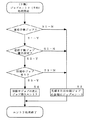
図11は、子機の印刷ジョブがエントリされた時の制御フローである。連結印刷ジョブであり(S1−Y)かつ連結ジョブ優先設定であり(S2−Y)かつ印刷中ジョブが有る(S3−Y)場合、印刷ジョブの次にこのジョブを挿入(エントリ)する(S4)。それ以外の条件では、全印刷ジョブの最後にエントリする(S5)。
【0053】
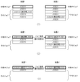
図12は、連結子機ジョブを全ジョブの後端にエントリする設定の場合の図である。子機の印刷ジョブはJOB22の印刷中にエントリされるが、既に子機のコピージョブJOB23がエントリされているため、連結子機ジョブはJOB23の後に印刷実行開始される。
【0054】
図13は、連結子機ジョブを印刷中ジョブの直後にエントリする設定の場合の図である。子機の印刷ジョブはJOB22の印刷中にエントリされると、既にエントリ済みのジョブJOB23の前に挿入され、JOB22が終了した後、印刷実行開始される。
【0055】
前者(図12)は、子機単体の印刷ジョブを優先したい要望に応じることが出来、後者(図13)は、連結コピージョブを優先したい要望に応じることが出来る。
【0056】
次に、印刷ジョブのエントリ状況を可視化した「ジョブリスト」の管理における本発明のメリットについて説明する。
【0057】
図14、図15は、左側が装置1、右側が装置2のジョブリストを示した図である。この図は操作パネルのLCD上にユーザに理解出来る形で表示することになるが、発明の本質には影響ないので説明は割愛する。図は、それぞれ時間の経過とともに、−1,−2,−3という順に並べている。
【0058】
まず、図14(1)は、ある時点の装置1,装置2のそれぞれのジョブエントリ(予約)状況を示している。装置1では、JOB11、JOB12、JOB13(連結親JOB)、JOB14、JOB15、JOB25(連結子JOB)という順にエントリされている。装置2では、JOB21、JOB22 、JOB23、JOB24、JOB13(連結子ジョブ)、JOB25(連結親ジョブ)という順にエントリされている。JOB13は、装置1で操作された連結コピージョブであり、JOB25は、装置2から操作された連結コピージョブである。
【0059】
この装置1、2にエントリされたジョブは、そのまま実行される場合には図8に示した通りの動作で実行され、なんら不具合を生じない。しかし、ジョブの順序を図14(2)のように入れ替えた場合、時間の経過と共に図14(3)で示す状態となって、どちらも連結親ジョブのジョブ順がまわってこず、デッドロックしてしまう。
【0060】
一方、本発明の方式で図14(1)と同じ手順のジョブを実行させようとした時のジョブリストの状態が、図15(1)である。本発明では、子機の印刷ジョブは親機の印刷ジョブの開始と同期するため、連結親ジョブの順番が回ってきた段階(図15(2)、図15(3))に初めて、子機の印刷ジョブがエントリ・実行要求される。
【0061】
このような制御によって、いつジョブリスト内のジョブ順を変更しても、図14で示すようなデッドロックが発生しないことが示される。
【0062】
【発明の効果】
以上説明したように、請求項1の画像形成システムによれば、子機側が連結ジョブを実行する順番が来たときにジョブの予約(エントリ)を行うようにして、子機側の効率よい稼働と予約ジョブの入れ替えによる双方デッドロックを回避できる。
【0063】
請求項2の画像形成システムによれば、請求項1記載の画像形成システムにおいて、子機側のジョブの最後ではなく、印刷中ジョブの直後に挿入エントリすることによって、優先的に連結ジョブを実行可能になる。
【0064】
請求項3の画像形成システムによれば、請求項2記載の画像形成システムにおいて、子機側の単独ジョブを優先するか、連結子機ジョブを優先するかを選択設定可能にして、ユーザの利用環境に合わせることが可能になる。
【0065】
請求項4の画像形成システムによれば、請求項3記載の画像形成システムにおいて、設定を不揮発メモリに保持することにより、主電源投入時に再設定する必要を無くすことができる。
【0066】
請求項5記載の画像形成装置によれば、画像の入力を行う画像入力手段と、画像入力手段で入力された画像を記憶する入力画像記憶手段と、入力画像記憶手段から画像データを読み出して画像形成する第1の画像形成手段と、入力画像記憶手段に保持されている画像データを他の画像形成装置に転送するための画像データ転送手段と、他の画像形成装置とコマンドデータを送受信するコマンドデータ送受信手段と、他の画像形成装置から送信された画像データを記憶する送信画像データ記憶手段と、コマンドデータ送受信手段で受け取った要求に従って送信画像データ記憶手段から画像データを読み出して画像形成する第2の画像形成手段と、上記各手段を制御する制御手段と、画像形成処理のジョブを、読み取りジョブと印刷ジョブとの組み合わせで管理するジョブ管理手段と、第1の印刷ジョブが稼働中に、第2の印刷単独ジョブを予約する、あるいは第2の印刷ジョブの読み取りジョブを先行動作させ、前記第2の印刷ジョブを予約するジョブ予約手段と、投入されたジョブ順に画像形成する順序管理手段とを有することを特徴としているので、子機側の効率よい稼働と予約ジョブの入れ替えによる双方デッドロックを回避できる。
【図面の簡単な説明】
【図1】本発明の実施形態である画像形成装置の内部構成を示す断面図である。
【図2】画像形成装置の操作部を示す外観図である。
【図3】操作部の液晶タッチパネルを示す外観図である。
【図4】の構成を示すブロック図である。
【図5】画像処理部の構成を示すブロック図である。
【図6】セレクタにおける1ページ分の画像信号について説明する。
【図7】ソフトウェアのモジュール構成を示す図である。
【図8】従来の連結コピージョブの制御を視覚化した説明図である。
【図9】本発明の連結コピージョブの制御を視覚化した説明図である。
【図10】子機の連結印刷ジョブの優先設定を行う画面フロー図である。
【図11】子機の印刷ジョブがエントリされた時の制御フロー図である。
【図12】連結子機ジョブを全ジョブの後端にエントリする設定の場合の図である。
【図13】連結子機ジョブを印刷中ジョブの直後にエントリする設定の場合の図である。
【図14】従来の連結コピージョブのジョブリストを示す図である。
【図15】本発明の連結コピージョブのジョブリストを示す図である。
【符号の説明】
1 自動原稿送り装置(ADF)
2 原稿台
3 給送ローラ
4 給送ベルト
5 排送ローラ
6 コンタクトガラス
7 原稿セット検知
8 第1トレイ
9 第2トレイ
10 第3トレイ
11 第1給紙ユニット
12 第2給紙ユニット
13 第3給紙ユニット
14 縦搬送ユニット
15 感光体
16 搬送ベルト
17 定着ユニット
18 排紙ユニット
20 メインコントローラ
21 中間クラッチ
30 操作部
31 液晶ディスプレイ
49 IPU
50 読み取りユニット
51 露光ランプ
52 第1ミラー
53 レンズ
54 CCDイメージセンサ
55 第2ミラー
56 第3ミラー
57 書き込みユニット
58 レーザ出力ユニット
59 結像レンズ
60 ミラー
100 フィニシャ
101 分岐偏向板
102 スタッカ搬送ローラ
103 スタッカ排紙ローラ
104 スタッカ・トレイ
105 ステープラ搬送ローラ
106 ステープラ
107 ステープラ排紙ローラ
108 ステープル・トレイ
109 落下ストッバ
110 落下トレイ
111 両面給紙ユニット
112 分岐爪[0001]
TECHNICAL FIELD OF THE INVENTION
The present invention relates to an image forming system and an image forming apparatus that use a plurality of electrically connectable image forming apparatuses to share a printing function and enable linked printing.
[0002]
[Prior art]
2. Description of the Related Art Conventionally, an image forming apparatus capable of reserving a job while a reading unit or an image memory is available during execution of the job has been considered. On the other hand, a technique is known in which a plurality of digital copying machines are functionally connected and used. The connection mode is selected on the parent device side, the read image is shared by the connected child devices, and the printing operation is performed in parallel, thereby improving the performance. For example, when copying 100 originals, if there are two image forming apparatuses in a connected state, the printing time can be reduced by performing the printing operation for 50 sheets per one.
[0003]
As an example of the related art, there is an “image forming apparatus, an information processing system, an image forming method, and a storage medium” having a job reservation and an order changing function (for example, see Patent Document 1). Further, there is an “image forming apparatus” having a job reservation function (for example, see Patent Document 2).
[0004]
[Patent Document 1]
Japanese Patent Application Laid-Open No. 2000-47530 [Patent Document 2]
JP-A-11-88570
[Problems to be solved by the invention]
However, in the system having the connection function of the conventional image forming apparatus and the job reservation function, when the job of the child device is reserved at the same time when the job of the parent device is reserved, until the connection job of the parent device is completed, Execution of the slave unit alone job may be hindered, or execution of both reservation jobs may be hindered by each other depending on the result of changing the reservation order.
[0006]
SUMMARY OF THE INVENTION The present invention has been made in view of the above-described problem, and makes a reservation (entry) of a job when the slave unit comes to execute a linked job, thereby achieving efficient operation of the slave unit. An object of the present invention is to provide an image forming system and an image forming apparatus that efficiently control a linked job while avoiding both deadlocks caused by replacement of a reserved job.
[0007]
It is another object of the present invention to provide an image forming system and an image forming apparatus in which a linked job is preferentially operated by making an entry at the end of a printing job, not at the end of a job on the slave side. .
[0008]
Further, the present invention enables selection and setting of whether to give priority to a single job on the slave unit side or to give priority to a linked slave unit job, to enable the user environment to be adjusted, and to store setting information in a non-volatile memory. The object of the present invention is to provide an image forming system and an image forming apparatus which eliminate the necessity of resetting when the main power is turned on.
[0009]
[Means for Solving the Problems]
In order to achieve the above object, an image forming system according to
[0010]
In the image forming system according to the second aspect, in the image forming system according to the first aspect, the print jobs registered in order in the second image forming apparatus are a job currently being printed by the second image forming apparatus and reserved thereafter. When there is a job that has been printed, insertion is reserved next to the job being printed.
[0011]
An image forming system according to a third aspect of the present invention is the image forming system according to the second aspect, wherein a print job to be sequentially registered in the second image forming apparatus is reserved for insertion immediately after the job being printed, or the entire reserved job is set. Is characterized in that it has a selection means for making a reservation or selecting at the end of.
[0012]
An image forming system according to a fourth aspect of the present invention is the image forming system according to the third aspect, further comprising a non-volatile memory for storing setting information, and storing a selected state in the non-volatile memory.
[0013]
According to a fifth aspect of the present invention, there is provided an image forming apparatus for inputting an image, input image storing means for storing an image input by the image input means, and reading image data from the input image storing means to form an image. First image forming means, image data transfer means for transferring image data held in the input image storage means to another image forming apparatus, and command data transmission / reception for sending / receiving command data to / from another image forming apparatus Means, image data storage means for storing image data transmitted from another image forming apparatus, and second means for reading out image data from the image data storage means in accordance with a request received by the command data transmitting / receiving means and forming an image. An image forming unit, a control unit that controls the above units, and a job of the image forming process, which is a combination of a read job and a print job. And a job management unit that manages the second print job while the first print job is in operation, or reserves the second print job by preliminarily operating a read job of the second print job. It is characterized by having a job reserving means for executing the job and an order managing means for forming an image in the order of the input jobs.
[0014]
BEST MODE FOR CARRYING OUT THE INVENTION
Hereinafter, embodiments of the present invention will be described in detail with reference to the accompanying drawings.
[0015]
FIG. 1 shows an image forming apparatus of the present invention. When the start key 34 on the
[0016]
The transfer sheets stacked on the first tray 8, the
[0017]
The
[0018]
The transfer paper stacked on the staple table 108 is aligned with the
[0019]
On the other hand, the normal
[0020]
When images are formed on both sides of the transfer sheet, the transfer sheet fed and imaged from each of the paper feed trays 8 to 10 is not guided to the
[0021]
Thereafter, the transfer paper stocked in the duplex paper supply unit 111 is re-fed from the duplex paper supply unit 111 in order to transfer the toner image formed on the photoconductor 15 again, and a branch claw 112 for switching the path. Is set on the lower side, and guided to the
[0022]
Next, as shown in FIG. 4, the photoconductor 15, the conveyance belt 16, the fixing unit 17, the
[0023]
FIG. 2 is a diagram illustrating the
[0024]
FIG. 3 is a diagram illustrating an example of a display on the liquid crystal touch panel 31 of the
[0025]
In FIG. 3, the upper left is a message area for displaying a message such as "Ready to copy" or "Please wait", and the right is a copy number display for displaying the number of sheets set, and an automatic sheet for automatically selecting a transfer sheet. Selection key, sort key to specify the process to arrange copies one by one in the page order, stack key to specify the process to sort copies by page, staple key to specify the process to bind the sorted items one by one, The same-size key for setting the same size, the scaling key for setting the enlargement / reduction ratio, the two-sided key for setting the duplex mode, the edit key for setting the binding margin mode, etc., and the cover / interleaf for setting the cover / interleaf mode The key is a link mode key for printing out a large number of print operations by dividing them into a plurality of print operations via a digital copier network.
[0026]
Further, the state of the paper feed tray corresponding to the number of paper feed trays is shown, and a key for manually setting the paper feed tray is displayed for each paper feed tray.
[0027]
With reference to FIG. 1, the image reading means and the operation up to the formation of a latent image on a recording surface according to the present invention will be described. A latent image is a potential distribution generated by converting an image into optical information and irradiating the image on the photoreceptor surface.
[0028]
The reading unit 50 includes a
[0029]
The
[0030]
The laser light emitted from the laser output unit 58 is polarized by a polygon mirror that rotates at a constant speed, passes through the imaging lens 59, is turned back by the mirror 60, and forms a focused image on the surface of the photoconductor.
[0031]
The polarized laser light is exposed and scanned in a direction (main scanning direction) orthogonal to the direction in which the photoconductor rotates, and performs recording in units of lines of an image signal output from a selector 64 of an image processing unit described later. An image (electrostatic latent image) is formed on the photoconductor surface by repeating main scanning at a predetermined cycle corresponding to the rotation speed of the photoconductor and the recording density.
[0032]
As described above, the laser light output from the
[0033]
The configuration of the image processing unit (image reading unit and image writing unit) in the present embodiment will be described with reference to FIG. The light emitted from the exposure lamp 51 irradiates the original surface, and the reflected light from the original surface is imaged and received by an image forming lens (not shown) by the
[0034]
A CPU 68 for setting the image memory controller 65 and the like and controlling the reading unit 50 and the
[0035]
Here, an image signal for one page in the selector 64 will be described with reference to FIG.
[0036]
/ FGATE indicates the effective period of one page of image data in the sub-scanning direction. / LSYNC is a main scanning synchronization signal for each line, and the image signal becomes valid at a predetermined clock after this signal rises. A signal indicating that the image signal in the main scanning direction is valid is / LGATE. These signals are synchronized with the pixel clock VCLK, and data of one pixel is sent for one cycle of VCLK. The image processing unit (IPU) 49 has a separate / FGATE, / LSYNC, / LGATE, and VCLK generation mechanism for image input and output, respectively, and enables various combinations of image input / output. .
[0037]
Further, in order to share work, it is necessary to transmit and receive image data and commands to and from another digital copying machine. In this embodiment, the connection interface of IEEE 1394 is used for transmitting and receiving image data. A serial communication line is used. The memory controller of FIG. 5 realizes this via the connection interface driver 80.
[0038]
Next, a software control module configuration in the image forming apparatus, image transfer, and print control will be described. FIG. 7 is a diagram illustrating a software module configuration.
[0039]
The job information set in the application layer is transferred to the control service layer with a start key or the like as a trigger. The control service layer interprets job information from the application and requests process information for operating the handler layer from the handler manager. The handler manager operates individual handlers according to the process information. Handlers include a scanner handler that controls the reading unit, an image memory handler that controls the input and output of image data to and from the image memory, and a plotter handler that controls the writing unit, paper transport, and post-processing peripherals. In cooperation with each other, the processes from reading to storage in the image memory and image formation are performed.
[0040]
Further, the image forming apparatus is provided with a connection I / F driver for connecting with another image forming apparatus, so that image data and command information can be exchanged via this I / F.
[0041]
In the case of a single copy job, the procedure of reading and storing an image and the procedure of printing a stored image are performed. In the case of a linked copy job, the following control is added in addition to the above procedure.
[0042]
For the linked copy job that occurred on the parent machine, the job information is interpreted in the control service of the parent machine, then the process of storing the image read by the scanner in the image memory and transferring the image to the image memory of the child machine To be executed separately.
[0043]
When the required image transfer is completed, the control service of the slave unit generates a print process that refers to the image data that has been transferred in advance, according to the information received from the control service of the master unit, and prints the print process on the handler manager of the slave unit. Request.
[0044]
Then, the control service of the slave unit notifies the master unit of the print job processed by the master unit sequentially. According to this information, the control service of the master unit monitors the progress of the print job of its own unit and the print job of the slave unit, and performs printing as needed.
[0045]
The details of the present invention will be described with reference to FIG. First, when a linked copy job is performed, as described above, the master machine is categorized into execution of a reading job, accumulation of image data, entry (reservation) and execution of a master machine print job, and Is divided into procedures of transferring image data, and entering (reserving) and executing a slave device print job. Since the master unit controls distribution of all print jobs, the print job of the slave unit is executed at least after the start of the print job of the master unit. FIGS. 8 and 9 show these visualizations. In the linked image forming system according to the present invention, any device can execute a copy job as a parent device.
[0046]
FIGS. 8 and 9 are diagrams in which a copy job is reserved and executed in the order of the master unit independent jobs JOB11 and JOB12, and the horizontal axis represents time when the linked copy job JOB13 is transitioned. In the slave unit, the slave unit alone copy jobs JOB21, 22, and 23 are reserved and executed.
[0047]
First, in the control of the conventional linked copy job (FIG. 8), the print jobs of the master unit and the slave unit are entered in synchronization with the start of the reading job (200). On the other hand, in the control of the linked copy job of the present invention (FIG. 9), the print job of the slave unit is entered in synchronization with the start of the print job of the master unit (203).
[0048]
In the conventional control (FIG. 8), since the connection job of the slave unit is performed after the
[0049]
By performing such linked copy job control, the time required to complete all jobs can be reduced by the amount indicated by 207.
[0050]
Next, the control for entering the linked job of the slave unit at the rear end and the control for inserting immediately after the printing job will be described with reference to FIGS.
[0051]
FIG. 10 is a screen flow for setting whether to prioritize the linked print job of the slave unit. When the
[0052]
FIG. 11 is a control flow when a print job of a slave unit is entered. If the job is a linked print job (S1-Y), the linked job priority setting is set (S2-Y), and there is a job being printed (S3-Y), this job is inserted (entry) next to the print job (S4). ). Otherwise, the entry is made at the end of all print jobs (S5).
[0053]
FIG. 12 is a diagram illustrating a case in which the setting is made such that the linked slave job is entered at the end of all jobs. The print job of the slave unit is entered during the printing of JOB22, but since the copy job JOB23 of the slave unit has already been entered, the linked slave unit job starts printing after the job23.
[0054]
FIG. 13 is a diagram illustrating a case where a setting is made such that a linked slave job is entered immediately after a printing job. When the print job of the slave unit is entered during the printing of the
[0055]
The former (FIG. 12) can respond to a request to give priority to a print job of the slave unit alone, and the latter (FIG. 13) can respond to a request to give priority to a linked copy job.
[0056]
Next, advantages of the present invention in managing a “job list” in which the entry status of a print job is visualized will be described.
[0057]
14 and 15 are diagrams illustrating a job list of the
[0058]
First, FIG. 14A shows the job entry (reservation) status of each of the
[0059]
When the jobs entered in the
[0060]
On the other hand, FIG. 15A shows the state of the job list when the job of the same procedure as that of FIG. 14A is executed by the method of the present invention. In the present invention, since the print job of the slave unit is synchronized with the start of the print job of the master unit, the slave unit first starts at the stage when the order of the linked parent job comes (FIGS. 15 (2) and 15 (3)). Print job is requested for entry and execution.
[0061]
By such control, it is shown that deadlock does not occur as shown in FIG. 14 even when the order of the jobs in the job list is changed.
[0062]
【The invention's effect】
As described above, according to the image forming system of the first aspect, the slave unit makes a reservation (entry) for the job when the turn to execute the linked job comes, so that the slave unit can operate efficiently. Deadlock due to replacement of reserved jobs and reserved jobs can be avoided.
[0063]
According to the image forming system of the second aspect, in the image forming system of the first aspect, the linked job is preferentially executed by inserting the entry immediately after the job being printed, not at the end of the job on the slave side. Will be possible.
[0064]
According to the image forming system of the third aspect, in the image forming system of the second aspect, it is possible to selectively set whether to give priority to a single job on the slave unit side or to give priority to a linked slave unit job, and use by a user. It can be adjusted to the environment.
[0065]
According to the image forming system of the fourth aspect, in the image forming system of the third aspect, it is possible to eliminate the necessity of resetting when the main power is turned on by holding the setting in the nonvolatile memory.
[0066]
According to the image forming apparatus of the present invention, an image input means for inputting an image, an input image storage means for storing an image input by the image input means, and an image data read from the input image storage means. First image forming means for forming, image data transfer means for transferring image data held in the input image storage means to another image forming apparatus, and a command for transmitting and receiving command data to and from another image forming apparatus A data transmission / reception unit, a transmission image data storage unit for storing image data transmitted from another image forming apparatus, and an image forming unit which reads out image data from the transmission image data storage unit in accordance with a request received by the command data transmission / reception unit and forms an image. Image forming means, control means for controlling each of the above means, and a job of image forming processing as a set of a read job and a print job. A job management unit that manages the second print job while the first print job is operating, reserves the second print job alone, or precedes the read job of the second print job to execute the second print job. It is characterized by having a job reserving means for reserving and an order managing means for forming images in the order of input jobs, so that both the efficient operation on the slave side and deadlock due to replacement of the reserved job can be avoided.
[Brief description of the drawings]
FIG. 1 is a cross-sectional view illustrating an internal configuration of an image forming apparatus according to an embodiment of the present invention.
FIG. 2 is an external view illustrating an operation unit of the image forming apparatus.
FIG. 3 is an external view showing a liquid crystal touch panel of an operation unit.
FIG. 4 is a block diagram showing the configuration of FIG.
FIG. 5 is a block diagram illustrating a configuration of an image processing unit.
FIG. 6 illustrates an image signal for one page in a selector.
FIG. 7 is a diagram showing a module configuration of software.
FIG. 8 is an explanatory diagram visualizing control of a conventional linked copy job.
FIG. 9 is an explanatory diagram visualizing control of a linked copy job according to the present invention.
FIG. 10 is a screen flow diagram for performing priority setting of a linked print job of a slave unit.
FIG. 11 is a control flowchart when a print job of a slave unit is entered.
FIG. 12 is a diagram illustrating a case where a setting is made such that a linked slave job is entered at the end of all jobs.
FIG. 13 is a diagram illustrating a case where a setting is made so that a linked slave job is entered immediately after a printing job.
FIG. 14 is a diagram showing a job list of a conventional linked copy job.
FIG. 15 is a diagram illustrating a job list of a linked copy job according to the present invention.
[Explanation of symbols]
1 Automatic Document Feeder (ADF)
2 Document table 3
Reference numeral 50 Reading unit 51
Claims (5)
前記画像入力手段にて入力された前記画像を記憶する第1の記憶手段と、
前記第1の記憶手段から画像データを読み出して画像形成する第1の画像形成手段と、
前記第1の記憶手段に保持されている前記画像データを他の画像形成装置に転送するための画像データ転送手段と、
他の画像形成装置間でコマンドデータを送受信するコマンドデータ送受信手段と、
上記各手段を制御する第1の制御手段とを有する第1の画像形成装置と、
前記第1の画像形成装置から前記画像データ転送手段で送られた前記画像データを記憶する第2の記憶手段と、
前記コマンドデータ送受信手段で受け取った要求に従って前記第2の記憶手段から前記画像データを読み出して画像形成する第2の画像形成手段と、
上記各手段を制御する第2の制御手段とを有する複数の画像形成装置とが接続された連結画像形成システムであって、
画像形成処理のジョブを、読み取りジョブと印刷ジョブとの組み合わせで管理するジョブ管理手段と、
第1の印刷ジョブが稼働中に、第2の印刷単独ジョブを予約する、あるいは第1の印刷ジョブが稼働中に、第2の印刷ジョブの読み取りジョブを先行動作させ、前記第2の印刷ジョブを予約するジョブ予約手段と、
投入されたジョブ順に画像形成する順序管理手段とを有し、
第2の画像形成装置の印刷ジョブを順序登録する時期を、第1の画像形成装置の印刷ジョブ開始に同期させることを特徴とする画像形成システム。Image input means for inputting an image,
First storage means for storing the image input by the image input means,
First image forming means for reading out image data from the first storage means and forming an image;
Image data transfer means for transferring the image data held in the first storage means to another image forming apparatus;
Command data transmitting and receiving means for transmitting and receiving command data between other image forming apparatuses,
A first image forming apparatus having first control means for controlling each of the above means,
A second storage unit for storing the image data transmitted by the image data transfer unit from the first image forming apparatus;
A second image forming unit that reads the image data from the second storage unit and forms an image according to a request received by the command data transmitting / receiving unit;
A linked image forming system in which a plurality of image forming apparatuses having a second control unit for controlling each of the above units are connected;
A job management unit that manages a job of the image forming process by a combination of a read job and a print job;
Reserving a second print-only job while the first print job is running, or pre-operating a read job of the second print job while the first print job is running, Means for reserving a job,
Sequence management means for forming images in the order of the input jobs,
An image forming system comprising: synchronizing a timing of orderly registering a print job of a second image forming apparatus with a start of a print job of the first image forming apparatus.
前記画像入力手段で入力された前記画像を記憶する入力画像記憶手段と、
前記入力画像記憶手段から画像データを読み出して画像形成する第1の画像形成手段と、
前記入力画像記憶手段に保持されている前記画像データを他の画像形成装置に転送するための画像データ転送手段と、
前記他の画像形成装置とコマンドデータを送受信するコマンドデータ送受信手段と、
他の画像形成装置から送信された前記画像データを記憶する送信画像データ記憶手段と、
前記コマンドデータ送受信手段で受け取った要求に従って前記送信画像データ記憶手段から前記画像データを読み出して画像形成する第2の画像形成手段と、
上記各手段を制御する制御手段と、
画像形成処理のジョブを、読み取りジョブと印刷ジョブとの組み合わせで管理するジョブ管理手段と、
第1の印刷ジョブが稼働中に、第2の印刷単独ジョブを予約する、あるいは第2の印刷ジョブの読み取りジョブを先行動作させ、前記第2の印刷ジョブを予約するジョブ予約手段と、
投入されたジョブ順に画像形成する順序管理手段と、
を有することを特徴とする画像形成装置。Image input means for inputting an image,
Input image storage means for storing the image input by the image input means,
First image forming means for reading out image data from the input image storage means and forming an image,
Image data transfer means for transferring the image data held in the input image storage means to another image forming apparatus,
Command data transmitting and receiving means for transmitting and receiving command data to and from the other image forming apparatus,
Transmission image data storage means for storing the image data transmitted from another image forming apparatus,
A second image forming unit that reads out the image data from the transmission image data storage unit and forms an image according to a request received by the command data transmission / reception unit;
Control means for controlling each of the above means,
A job management unit that manages a job of the image forming process by a combination of a read job and a print job;
A job reservation unit for reserving the second print job while the first print job is running, or preliminarily operating the read job of the second print job to reserve the second print job;
Order management means for forming images in the order of the input jobs;
An image forming apparatus comprising:
Priority Applications (1)
| Application Number | Priority Date | Filing Date | Title |
|---|---|---|---|
| JP2003007677A JP2004222003A (en) | 2003-01-15 | 2003-01-15 | Image forming system and image forming apparatus |
Applications Claiming Priority (1)
| Application Number | Priority Date | Filing Date | Title |
|---|---|---|---|
| JP2003007677A JP2004222003A (en) | 2003-01-15 | 2003-01-15 | Image forming system and image forming apparatus |
Publications (1)
| Publication Number | Publication Date |
|---|---|
| JP2004222003A true JP2004222003A (en) | 2004-08-05 |
Family
ID=32897701
Family Applications (1)
| Application Number | Title | Priority Date | Filing Date |
|---|---|---|---|
| JP2003007677A Pending JP2004222003A (en) | 2003-01-15 | 2003-01-15 | Image forming system and image forming apparatus |
Country Status (1)
| Country | Link |
|---|---|
| JP (1) | JP2004222003A (en) |
Cited By (1)
| Publication number | Priority date | Publication date | Assignee | Title |
|---|---|---|---|---|
| JP2011155466A (en) * | 2010-01-27 | 2011-08-11 | Kyocera Mita Corp | Image processing apparatus |
-
2003
- 2003-01-15 JP JP2003007677A patent/JP2004222003A/en active Pending
Cited By (1)
| Publication number | Priority date | Publication date | Assignee | Title |
|---|---|---|---|---|
| JP2011155466A (en) * | 2010-01-27 | 2011-08-11 | Kyocera Mita Corp | Image processing apparatus |
Similar Documents
| Publication | Publication Date | Title |
|---|---|---|
| JP2006184940A (en) | Image forming apparatus, software upgrade control method and program, and computer-readable information recording medium on which the same is recorded | |
| JP4056402B2 (en) | Image forming apparatus network system, image forming apparatus, connection operation method, and program | |
| JP2000047536A (en) | Coupling method of copier network system | |
| JP4121020B2 (en) | Image forming system | |
| JP4121019B2 (en) | Image forming apparatus network system | |
| JP3858192B2 (en) | Image forming system and image forming method | |
| JP4004412B2 (en) | Image forming apparatus | |
| JP4171348B2 (en) | Image forming system | |
| JP4039954B2 (en) | Image forming system | |
| JP2004222003A (en) | Image forming system and image forming apparatus | |
| JP4366090B2 (en) | Image forming system and image forming apparatus | |
| JP4012827B2 (en) | Image forming system, image forming apparatus, and image forming method | |
| JP2000276310A (en) | Image forming system | |
| JP3614657B2 (en) | Image forming apparatus | |
| JP4074201B2 (en) | Image forming apparatus | |
| JP4113818B2 (en) | Image forming connection system | |
| JP2004220092A (en) | Image forming device | |
| JP2005074678A (en) | Image forming system | |
| JPH10322533A (en) | Copier and copier network system | |
| JP2005094707A (en) | Image forming system and image forming apparatus | |
| JP2005333388A (en) | Image forming system and image forming apparatus | |
| JPH10153928A (en) | Copier network system | |
| JP2005094525A (en) | Image forming system | |
| JP2004215029A (en) | Image forming apparatus and image forming system | |
| JP2006256154A (en) | Image forming apparatus and image forming method |
Legal Events
| Date | Code | Title | Description |
|---|---|---|---|
| A621 | Written request for application examination |
Free format text: JAPANESE INTERMEDIATE CODE: A621 Effective date: 20050822 |
|
| A131 | Notification of reasons for refusal |
Free format text: JAPANESE INTERMEDIATE CODE: A131 Effective date: 20070605 |
|
| A521 | Written amendment |
Free format text: JAPANESE INTERMEDIATE CODE: A523 Effective date: 20070803 |
|
| A02 | Decision of refusal |
Free format text: JAPANESE INTERMEDIATE CODE: A02 Effective date: 20070911 |