【0001】
【発明の属する技術分野】
本発明は、エアバッグ展開時に開くエアバッグドアがインストルメントパネル本体に一体に形成されたエアバッグドア一体型インストルメントパネルに関する。
【0002】
【従来の技術】
従来、下記特許文献1に記載のような、インストルメントパネル本体に、エアバッグ側から表面に至らない破断線によってエアバッグドアを区画し、このエアバッグドアのヒンジ部を前記パネル本体にエアバッグ側から設けられた薄肉部によって形成するエアバッグドア一体方インストルメントパネルが知られている。
【0003】
また、下記特許文献2に記載のような、エアバッグドアのヒンジ部を、前記パネル本体にエアバッグ側から設けられた薄肉部と、前記パネル本体内に埋設された金属製長繊維集合体とによって形成するエアバッグドア一体型インストルメントパネルが知られている。
【0004】
【特許文献1】
特開平11−240404号公報(段落0016、段落0017、図1)
【特許文献2】
特開平09−286293号公報(第楽0022、図1)
【0005】
【発明が解決しようとする課題】
特許文献1のものでは、パネル本体にエアバッグ側から設けられる薄肉部だけでヒンジ部を形成するため、確実に機能するヒンジ部が形成しにくいという問題点がある。
【0006】
特許文献2のものでは、パネル本体に金属製長繊維集合体を埋設してヒンジ部を形成するため、部品点数が増えるとともに、パネル本体の成形が難しくなるという問題点である。
【0007】
本発明は、前記課題に鑑みなされたものであり、パネル本体に一体にエアバッグドアを形成する場合であっても、簡単な構成で確実に機能するヒンジ部を形成することができるエアバッグドア一体型インストルメントパネルを提供することを目的とする。
【0008】
【課題を解決するための手段】
上記課題を解決する請求項1に係る発明は、エアバッグ展開時に開くエアバッグドアがインストルメントパネル本体に一体に形成されたエアバッグドア一体型インストルメントパネルであって、前記エアバッグドアは、前記パネル本体のエアバッグ側から設けられ、表面側から見えない破断部によって区画されており、前記エアバッグドア周囲のパネル本体と前記エアバッグドアとを連結するとともに、ヒンジ部を有する構造体が、前記エアバッグドア裏面と前記エアバッグドア周囲のパネル本体裏面とに接合により固定されていることを特徴とするものである。
【0009】
上記構成によると、パネル本体に破断部によってエアバッグドアが区画され、エアバッグドア裏面とその周囲のパネル本体裏面とが、ヒンジ部を有する構造体により固定されているため、構造体はヒンジ部として機能する。エアバッグがエアバッグドアを押す力で、エアバッグドアは破断部を起点としてバネル本体から開裂し、開裂したドアパネルは構造体に固定されているため、構造体のヒンジ部を起点として開く。パネル本体はエアバッグドアを破断部によって区画するだけであるため、パネル本体の構造及び材質に関する選択の自由度が広がる。
【0010】
請求項2に係る発明は、請求項1において、前記構造体は、前記エアバッグドア周囲に位置する枠体と、前記エアバッグドア裏面に位置するドア支持体と、このドア支持体と枠体とを連結するとともにヒンジ部が設けられた変形可能な連結部とを一体に成形したものである。
上記構成によると、ヒンジ部を有する連結部によりドア支持体が変位するため、開裂するドアパネルが展開し易い。また、エアバッグドアの周囲は枠体によって固定されているため、エアバッグドアの開裂は一層確実となる。
【0011】
請求項3に係る発明は、請求項2において、前記連結部は、エアバッグ側に向かって延在しながら、前記枠体に向かって湾曲するように形成されている。
上記構成によると、連結部が容易に変形できため、開裂するドアパネルは確実に展開する。
【0012】
請求項4に係る発明は、請求項2において、前記枠体に、エアバッグモジュールの係止部が設けられている。
上記構成によると、エアバッグドア周囲のパネル本体に固定された枠体にエアバッグモジュールの係止部を設けることにより、エアバッグモジュールの取り付けを兼ねた構造体とすることができる。
【0013】
請求項5に係る発明は、請求項2〜3のいずれかにおいて、前記構造体は、弾性体により形成されている。
上記構成によると、構造体は一体成形しやすく、連結部の変形を確保できる。また、パネル本体と同種の材料を選択することも可能になる。
【0014】
請求項6に係る発明は、請求項1において、前記インストルメントパネル本体は、樹脂の単層構造で形成されている。
上記構成によると、樹脂の単層構造のパネル本体であるため、ポリプロピレン樹脂のように傷つきにくく且つ熱変形の少ない樹脂を選択して、インビジブルなエアバッグドアをパネル本体に形成しても、エアバッグドアを構造体が確実に支持して展開可能とする。
【0015】
請求項7に係る発明は、請求項1において、前記接合は、振動溶着又は接着により面同士を突き合わせて行われている。
上記構成によると、面同士を突き合わせての振動溶着又は接着であるため、パネル本体と構造体との接合が容易且つ確実にできる。
【0016】
【発明の実施の形態】
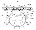
以下、図面を参照しつつ本発明の実施形態の一例を説明する。図1は、エアバッグドアをパネル本体に一体に有するエアバッグドア一体型インストルメントパネルの縦方向の部分断面図である。
【0017】
図1に示されるインストルメントパネル10は、車両の車室内に設けられている。その助手席側に位置するパネル本体21にはエアバッグドア11が一体に形成されている。このエアバッグドア11に対応するパネル本体21の裏面には構造体12が接合により固定されている。構造体12にはエアバッグ装置13が取り付けられている。
【0018】
インストルメントパネル10は、パネルを形成する樹脂製のパネル本体21からなる単層構造である。前記樹脂は、例えばポリプロピレンである。前記パネル本体21は、例えば射出成形により形成される。
【0019】
図示例のエアバッグドア11は、両開きドア式である。パネル本体21の裏面(エアバッグ側)から表面に至らない破断線である破断部22により、エアバッグドア11が区画されている。破断部22は、図2の二点鎖線に示すように、日の字型となっている。この日の字型の破断部22により、両側に開く一対の部分11a,11bからなるエアバッグドア11が形成される。破断部22を形成する破断線は、例えばレーザ加工による表面に達しない小孔の列で形成される。レーザ加工で破断部22を形成する場合、パネル本体21を形成した後に、別途のレーザ加工が施される。なお、破断部22は、レーザ加工による長手方向に連続した開先であってもよいし、射出成形時に同時に形成される連続又は不連続なV状ノッチであってもよい。また、日の字型破断部22のうち、H型の基本線を深くし、残りを浅くして、エアバッグドア11の一対の部分11a,11bの合わせ部分をより開き易くすることができる。
【0020】
このように、表面に至らない破断部22により、エアバッグドア11は、インストルメントパネル10の車室側から見えないインビジブルエアバッグドアとなっている。このエアバッグドア11は、パネル本体21に破断部22だけで区画されているため、パネル本体21の構造を単層とし、その材質として傷つきにくく且つ熱変形の少ないポリプロピレン等の硬質樹脂を選択することができる。
【0021】
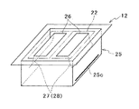
図2の斜視図に示されるように、構造体12は、エアバッグドア11の周囲に位置する枠体25と、エアバッグドア11の裏面に位置するドア支持体26と、ドア支持体26と枠体25とを連結すると共にヒンジ部28を有する連結部27とを、射出成形等で一体に成形したものである。この構造体12は、前記ヒンジ部28が機能するような弾性体で形成されている。この弾性体は、熱可塑性オレフィン又はポリカーボネイトから選ばれた一つであることが好ましい。
【0022】
図1において、枠体25は、4面を有する四角筒25aの先端にフランジ25bを形成したものである。四角筒25aには、後述するエアバッグ装置13を取り付ける係止孔(係止部)25cが設けられている。
【0023】
図1において、ドア支持体26は、エアバッグドア11の第1部分11aの裏面に突き合わされるように上面が平らな第1ドア支持体26aと、エアバッグドア11の第2部分11bの裏面に突き合わされるように上面が平らな第2ドア支持体26bとからなる。
【0024】
図1において、連結部27は、第1ドア支持体26aの端からエアバッグ側に延在しながら、四角筒25aの一面に向かって湾曲するように形成されている第1連結部27aと、第2ドア支持体26bの端からエアバッグ側に延在しながら、四角筒25aの一面に向かって湾曲するように形成されている第2連結部27bとからなる。
【0025】
第1連結部27aの第1ドア支持体26a側の端に薄肉部271aが形成されている。また、第1連結部27aは第1ドア支持体26aに向かって片持ち状となっており、その先端は四角枠筒25aに対して変形可能となっている。この変形可能な第1連結部27aと薄肉部271aとが第1ヒンジ部28aを形成する。
【0026】
第2連結部27bの第2ドア支持体26b側の端に薄肉部271bが形成されている。また、第2連結部27bは第2ドア支持体26bに向かって片持ち状となっており、その先端は四角枠筒25aに対して変形可能となっている。この変形可能な第2連結部27bと薄肉部271bとが第2ヒンジ部28bを形成する。
【0027】
図1において、エアバッグ装置13は、枠体4の係止部25cに係止されるエアバッグケース14を備えている。このエアバッグケース14の底部にはインフレータ15が配設されている。また、エアバッグケース14の開口部側には、エアバッグ16が展開可能に折り畳まれた状態で収納されている。
【0028】
構造体12のフランジ25bの上面と、パネル本体21のエアバッグドア11周囲の裏面とは、面同士を突き合わせ、接合により固定されている。構造体12の第1ドア支持体26aの上面と、エアバッグドア11の第1部分11aの裏面とは、面同士が突き合わせられた状態であり、両者は接合により固定されている。構造体12の第2ドア支持体26bの上面と、エアバッグドア11の第2部分11bの裏面とは、その面同士が突き合わせられた状態であり、両者は接合により固定されている。
【0029】
上記接合は、面同士を突き合わせて相対移動させ、摩擦熱で溶かして着ける振動溶着又は高周波溶着により行われる。パネル本体21の裏面に対して構造体12を押し付けつつ相対移動させると、接合が容易にできる。また、バネル本体21の材質と構造体12の材質とが共に熱可塑性樹脂である場合、上記振動溶着又は高周波溶着が容易且つ確実にできる。
【0030】
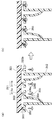
面同士を突き合わせての上記接合は、図4のように、熱かしめ接合とすることもできる。この場合、パネル本体221の材質は熱可塑性樹脂が選択される。
図4(a)において、エアバッグドア211周囲のパネル本体221に沿ってピン251を列状に突設するとともに、構造体212のフランジ225bにピン251に対応する位置に孔252を設ける。また、エアバッグドア211の第1部分211aと第2部分211bの各々にもピン253を突設するとともに、構造体212の第1ドア支持部226aと第2ドア支持部226bの各々にもピン253に対応する孔254を設ける。そして、図4(b)において、ピン251,253に孔252,254を通し、ピン251,254の頭を熱ゴテ等により押しつぶして接合する。
【0031】
また、上記接合は、図5のように、面同士を突き合わせることなく、ボルト接合とすることもできる。この場合、パネル本体321の材質と構造体312の材質に制限はなくなる。
図5(a)において、エアバッグドア311周囲のパネル本体321に沿って円柱状台座351を列状に突設するとともに、構造体212のフランジ225bに円柱状台座351に対応する位置に小孔352を設ける。また、エアバッグドア311の第1部分311aと第2部分311bの各々にも円柱状台座353を突設するとともに、構造体312の第1ドア支持部326aと第2ドア支持部326bの各々にも円柱状台座353に対応する小孔354を設ける。そして、図5(b)において、円柱状台座351,353の上に小孔352,354を位置させ、タップネジ355を円柱状台座351,353にねじ込み、構造体312をパネル本体321とエアバッグドア311の両方に対して接合状態で固定する。
【0032】
上記構成のエアバッグドア一体型インストルメントパネルの製造方法は以下の工程により行われる。
まず、パネル本体21を射出成形により形成する。この射出成形後又は射出成形と同時にインビジブルな破断部22を設けて、エアバッグドア11を形成する。この破断部22を、パネル本体21が射出成形され後に設ける場合でも、パネル本体21には構造体12が無い状態であるため、破断部22によるインビジブルなエアバッグドア11の形成は容易にできる。
このパネル本体21の成形とは別に、構造体12を射出成形により一体に形成する。
そして、エアバッグドア11を形成されたパネル本体21に対して構造体12を面同士が突き合わされる状態にし、振動溶着又は高周波溶着により両者を接合して固定する。
【0033】
以上のように、開裂可能なエアバッグドア11が形成されたパネル本体21と、ヒンジ部を有する構造体12の2部品を別々に成形し、両者を合わせて接合するという工程だけでエアバッグドア一体型インストルメントパネルが得られる。
また、部品点数も二つと最小限であるため、安価に製作することが可能になる。更に、エアバッグドア11が形成されたパネル本体21と、構造体12とをそれぞれ樹脂にすると、接合箇所も含めて、金属がないため、リサイクルし易いという利点を有する。
【0034】
上記構成のエアバッグドア一体型インストルメントパネルの作動を図3に基づいて説明する。
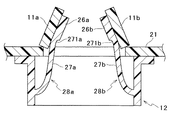
図示されないエアバッグが膨張すると、エアバッグドア11a,11bは、ドア支持体26a,26bを介して押し上げられる。エアバッグドア11a,11bは、破断部22を起点として裂けパネル本体21から分離される。一方、分離されたエアバッグドア11a,11bは、ドア支持部26a,26bに接合固定されているため、ヒンジ部28a,28bにより、図示のような開裂状態に維持される。
【0035】
ヒンジ部28a,28bは、薄肉部271a,271bと、変形可能な湾曲形状の連結部27a,27bとからなるため、構造体12に一体に形成されたヒンジ部28a,28bであっても、ヒンジ機能が確実に発揮される。
【0036】
上記構成のエアバッグドア一体型インストルメントパネルの実施形態は以下のように変更して実施することができる。
(1)パネル本体は、硬質樹脂の単層構造であるものが好ましいが、この構造に限られない。硬質樹脂のベース層に対して表面層を重ねた2層構造、または、硬質樹脂のベース層と表面層との間に発泡層を設けた3層構造であってもよい。このような2層構造又は3層構造の場合、インビジブルな破断部は、レーザ孔の列で形成し、ベース層を部分的に残し、レーザ孔の先端が表面層に至るようなもので形成することが好ましい。
【0037】
(2)エアバッグドアは、両開きが一般的であるが、片開きであってもよい。この場合、エアバッグドアは一部品となり、構造体のヒンジ部は図1のいずれか一方だけが備えられるものとすることができる。
【0038】
(3)構造体のヒンジ部は、薄肉部と変形可能な湾曲構造の連結部とで形成するものが好ましいがこれに限られない。ストレートな連結部と薄肉部との組み合わせ、薄肉部を有しない変形可能な湾曲構造の連結部だけでヒンジ部を構成するものであってもよい。
【0039】
(4)エアバッグドア11は、エアバッグの展開時にはパネル本体21から完全に分離される場合を説明したが、これに限らない。例えば、エアバッグドア11の破断部がH字状に設けられるともに、エアバッグドア11がパネル本体21にヒンジ部を有して設けられ、エアバッグドア11がパネル本体21に対して分離することなく開くものであってよい。
【0040】
【発明の効果】
上述した請求項1〜7によると、パネル本体と構造体の2点の部品点数により、確実に展開するエアバッグドア一体型インストルメントパネルとすることができる。構造体がパネル本体から切り離されているため、パネル本体に形成されるエアバッグドアは簡単な構造で形成できる。その結果、傷つきにくく且つ熱変形の少ない材料、例えばポリプロピレン樹脂でインビジブルエアバッグドアを形成することが可能になる。
【図面の簡単な説明】
【図1】本発明のエアバッグドア一体型インストルメントパネルの断面図である。
【図2】模式的に表された構造体の斜視図である。
【図3】本発明のエアバッグドア一体型インストルメントパネルの開裂時状態を示す断面図である。
【図4】パネル本体と構造体との他の接合方法を示す図である。
【図5】パネル本体と構造体との更に他の接合方法を示す図である。
【符号の説明】
10 インストルメントパネル
11 エアバッグドア
12 構造体
21 パネル本体
22 破断部
25 枠体
25c 係止孔(係止部)
26 ドア支持体
27 連結部
28 ヒンジ部[0001]
TECHNICAL FIELD OF THE INVENTION
The present invention relates to an instrument panel integrated with an airbag door in which an airbag door that opens when the airbag is deployed is formed integrally with an instrument panel body.
[0002]
[Prior art]
2. Description of the Related Art Conventionally, an airbag door is defined by a break line not extending from the airbag side to the surface in an instrument panel body as described in Patent Document 1 below, and a hinge portion of the airbag door is attached to the panel body by an airbag. 2. Description of the Related Art An instrument panel integrated with an airbag door formed by a thin portion provided from the side is known.
[0003]
Further, as described in Patent Literature 2 below, a hinge portion of an airbag door includes a thin portion provided on the panel body from the airbag side, and a metal long fiber aggregate embedded in the panel body. There is known an instrument panel integrated with an airbag door.
[0004]
[Patent Document 1]
JP-A-11-240404 (paragraph 0016, paragraph 0017, FIG. 1)
[Patent Document 2]
JP-A-09-286293 (No. 0022, FIG. 1)
[0005]
[Problems to be solved by the invention]
In Patent Document 1, since the hinge portion is formed only by the thin portion provided from the airbag side in the panel body, there is a problem that it is difficult to form a hinge portion that functions reliably.
[0006]
In Patent Document 2, the metal long fiber aggregate is buried in the panel body to form the hinge portion, so that the number of components increases and molding of the panel body becomes difficult.
[0007]
SUMMARY OF THE INVENTION The present invention has been made in view of the above-described problems, and even when an airbag door is formed integrally with a panel main body, an airbag door capable of forming a hinge portion that reliably functions with a simple configuration. It is an object to provide an integrated instrument panel.
[0008]
[Means for Solving the Problems]
The invention according to claim 1 that solves the above problem is an airbag door integrated type instrument panel in which an airbag door that opens when an airbag is deployed is formed integrally with an instrument panel body, wherein the airbag door includes: A structure that is provided from the airbag side of the panel main body and is partitioned by a broken portion that is not visible from the surface side, connects the panel main body around the airbag door and the airbag door, and has a hinge body. The airbag door is fixed to the backside of the airbag door and the backside of the panel body around the airbag door by bonding.
[0009]
According to the above configuration, the airbag door is partitioned by the break portion in the panel body, and the back surface of the airbag door and the back surface of the panel body around the airbag door are fixed by the structure having the hinge portion. Function as Due to the force of the airbag pushing the airbag door, the airbag door is torn from the panel body starting from the rupture portion, and the opened door panel is fixed to the structure, and thus opens from the hinge portion of the structure. Since the panel body only partitions the airbag door by the break, the degree of freedom in selecting the structure and material of the panel body is increased.
[0010]
According to a second aspect of the present invention, in the first aspect, the structure includes a frame positioned around the airbag door, a door support positioned on the back surface of the airbag door, and the door support and the frame. And a deformable connecting portion provided with a hinge portion is integrally formed.
According to the above configuration, since the door support is displaced by the connecting portion having the hinge portion, the door panel to be torn is easily deployed. In addition, since the periphery of the airbag door is fixed by the frame, the airbag door can be more reliably split.
[0011]
According to a third aspect of the present invention, in the second aspect, the connecting portion is formed so as to be curved toward the frame while extending toward the airbag.
According to the above configuration, the connecting portion can be easily deformed, so that the door panel that is torn can be reliably deployed.
[0012]
According to a fourth aspect of the present invention, in the second aspect, the frame is provided with a locking portion of the airbag module.
According to the above configuration, by providing the locking portion of the airbag module on the frame fixed to the panel body around the airbag door, it is possible to provide a structure that also serves to attach the airbag module.
[0013]
According to a fifth aspect of the present invention, in any one of the second to third aspects, the structure is formed of an elastic body.
According to the above configuration, the structure can be easily formed integrally, and deformation of the connecting portion can be ensured. It is also possible to select the same type of material as the panel body.
[0014]
According to a sixth aspect of the present invention, in the first aspect, the instrument panel main body is formed of a resin single-layer structure.
According to the above configuration, since the panel main body has a single-layer structure of resin, even if a resin that is hardly damaged and has low thermal deformation, such as a polypropylene resin, is selected and an invisible airbag door is formed in the panel main body, the air can be removed. The structure surely supports the bag door and enables the bag door to be deployed.
[0015]
According to a seventh aspect of the present invention, in the first aspect, the joining is performed by abutting surfaces by vibration welding or adhesion.
According to the above configuration, vibration welding or bonding is performed by abutting the surfaces, so that the panel body and the structure can be easily and reliably joined.
[0016]
BEST MODE FOR CARRYING OUT THE INVENTION
Hereinafter, an example of an embodiment of the present invention will be described with reference to the drawings. FIG. 1 is a vertical partial cross-sectional view of an airbag door-integrated instrument panel having an airbag door integrally with a panel body.
[0017]
The instrument panel 10 shown in FIG. 1 is provided in a vehicle cabin of a vehicle. An airbag door 11 is formed integrally with a panel body 21 located on the passenger seat side. The structure 12 is fixed to the back surface of the panel body 21 corresponding to the airbag door 11 by joining. An airbag device 13 is attached to the structure 12.
[0018]
The instrument panel 10 has a single-layer structure including a panel body 21 made of resin which forms the panel. The resin is, for example, polypropylene. The panel main body 21 is formed by, for example, injection molding.
[0019]
The airbag door 11 in the illustrated example is a double-door type. The airbag door 11 is defined by a break portion 22 which is a break line not extending from the back surface (airbag side) of the panel body 21 to the front surface. The break portion 22 has a sun-shape as shown by a two-dot chain line in FIG. The sun-shaped broken portion 22 forms the airbag door 11 including a pair of portions 11a and 11b that open to both sides. The break line forming the break portion 22 is formed by a row of small holes that do not reach the surface by, for example, laser processing. When forming the break part 22 by laser processing, a separate laser processing is performed after the panel main body 21 is formed. The break portion 22 may be a groove that is continuous in the longitudinal direction by laser processing, or may be a continuous or discontinuous V-shaped notch that is formed simultaneously during injection molding. Further, in the sun-shaped broken portion 22, the H-shaped basic line is made deep and the rest is made shallow, so that the joint portion of the pair of portions 11a and 11b of the airbag door 11 can be more easily opened.
[0020]
Thus, the airbag door 11 is an invisible airbag door that cannot be seen from the vehicle compartment side of the instrument panel 10 due to the broken portion 22 that does not reach the surface. Since the airbag door 11 is partitioned by the panel main body 21 only with the break portion 22, the panel main body 21 has a single-layer structure, and a hard resin such as polypropylene which is hardly damaged and has low thermal deformation is selected. be able to.
[0021]
As shown in the perspective view of FIG. 2, the structure 12 includes a frame 25 located around the airbag door 11, a door support 26 located on the back surface of the airbag door 11, and a door support 26. A connection part 27 having a hinge part 28 which is connected to the frame 25 and is integrally formed by injection molding or the like. The structure 12 is formed of an elastic body such that the hinge 28 functions. This elastic body is preferably one selected from thermoplastic olefin or polycarbonate.
[0022]
In FIG. 1, the frame 25 is formed by forming a flange 25b at the tip of a square tube 25a having four surfaces. The rectangular cylinder 25a is provided with a locking hole (locking portion) 25c for mounting the airbag device 13 described later.
[0023]
In FIG. 1, the door support 26 includes a first door support 26 a having a flat upper surface so as to abut against a back surface of the first portion 11 a of the airbag door 11, and a back surface of the second portion 11 b of the airbag door 11. And a second door support 26b having a flat upper surface so as to abut against the second door support 26b.
[0024]
In FIG. 1, the connecting portion 27 extends from the end of the first door support 26a toward the airbag, and is curved toward one surface of the square tube 25a. The second connecting portion 27b is formed so as to be curved toward one surface of the square cylinder 25a while extending from the end of the second door support 26b toward the airbag.
[0025]
A thin portion 271a is formed at an end of the first connecting portion 27a on the first door support 26a side. The first connecting portion 27a is cantilevered toward the first door support 26a, and its tip is deformable with respect to the square frame 25a. The deformable first connecting portion 27a and the thin portion 271a form a first hinge portion 28a.
[0026]
A thin portion 271b is formed at an end of the second connecting portion 27b on the side of the second door support 26b. The second connecting portion 27b is cantilevered toward the second door support 26b, and its tip is deformable with respect to the square frame 25a. The deformable second connecting portion 27b and the thin portion 271b form a second hinge portion 28b.
[0027]
In FIG. 1, the airbag device 13 includes an airbag case 14 locked by the locking portion 25 c of the frame 4. An inflator 15 is provided at the bottom of the airbag case 14. An airbag 16 is stored in the opening side of the airbag case 14 in a state where the airbag 16 can be deployed.
[0028]
The upper surface of the flange 25b of the structure 12 and the back surface around the airbag door 11 of the panel body 21 abut each other and are fixed by joining. The upper surface of the first door support 26a of the structure 12 and the back surface of the first portion 11a of the airbag door 11 are in a state where the surfaces abut each other, and both are fixed by joining. The upper surface of the second door support 26b of the structure 12 and the back surface of the second portion 11b of the airbag door 11 are in a state where the surfaces are butted together, and both are fixed by joining.
[0029]
The joining is performed by vibration welding or high-frequency welding in which the surfaces are butted relative to each other and are fused by friction heat. When the structure 12 is relatively moved while being pressed against the back surface of the panel main body 21, joining can be facilitated. When both the material of the panel body 21 and the material of the structural body 12 are thermoplastic resins, the above-described vibration welding or high-frequency welding can be performed easily and reliably.
[0030]
The joining in which the surfaces are butted with each other may be heat caulking as shown in FIG. In this case, the material of the panel body 221 is selected from a thermoplastic resin.
In FIG. 4A, pins 251 are provided in a row along the panel body 221 around the airbag door 211, and holes 252 are provided in the flange 225 b of the structure 212 at positions corresponding to the pins 251. Also, pins 253 protrude from each of the first portion 211a and the second portion 211b of the airbag door 211, and pins are also provided on each of the first door support portion 226a and the second door support portion 226b of the structure 212. A hole 254 corresponding to 253 is provided. Then, in FIG. 4B, the holes 252 and 254 are passed through the pins 251 and 253, and the heads of the pins 251 and 254 are crushed with a hot iron or the like to be joined.
[0031]
In addition, as shown in FIG. 5, the above-mentioned joining can be bolt joining without abutting the surfaces. In this case, the material of the panel body 321 and the material of the structure 312 are not limited.
In FIG. 5A, columnar pedestals 351 are provided in a row along the panel body 321 around the airbag door 311, and small holes are formed in the flanges 225 b of the structure 212 at positions corresponding to the columnar pedestals 351. 352 are provided. Further, a columnar pedestal 353 is also protruded from each of the first portion 311a and the second portion 311b of the airbag door 311. Each of the first and second door support portions 326a and 326b of the structure 312 is provided. Also, a small hole 354 corresponding to the cylindrical pedestal 353 is provided. In FIG. 5B, the small holes 352 and 354 are positioned on the cylindrical pedestals 351 and 353, and the tap screws 355 are screwed into the cylindrical pedestals 351 and 353, and the structure 312 is connected to the panel body 321 and the airbag door. 311 is fixed in a joined state.
[0032]
The method for manufacturing the airbag door integrated instrument panel having the above configuration is performed by the following steps.
First, the panel main body 21 is formed by injection molding. After or at the same time as the injection molding, an invisible break portion 22 is provided to form the airbag door 11. Even when the break portion 22 is provided after the panel main body 21 is injection-molded, since the panel body 21 has no structure 12, the breakable portion 22 can easily form the invisible airbag door 11.
Apart from the molding of the panel body 21, the structure 12 is integrally formed by injection molding.
Then, the structure 12 is brought into a state where the surfaces thereof abut against the panel main body 21 on which the airbag door 11 is formed, and the two are joined and fixed by vibration welding or high frequency welding.
[0033]
As described above, the airbag door is formed only by the steps of separately forming the two parts of the panel body 21 having the cleavable airbag door 11 formed thereon and the structure 12 having the hinge portion, and joining the two together. An integrated instrument panel is obtained.
Further, since the number of parts is as small as two, it can be manufactured at low cost. Furthermore, when the panel body 21 on which the airbag door 11 is formed and the structure 12 are made of resin, respectively, there is an advantage that there is no metal including the joints, so that it is easy to recycle.
[0034]
The operation of the airbag door integrated instrument panel having the above configuration will be described with reference to FIG.
When an airbag (not shown) is inflated, the airbag doors 11a and 11b are pushed up through the door supports 26a and 26b. The airbag doors 11 a and 11 b are separated from the tear panel main body 21 starting from the break portion 22. On the other hand, since the separated airbag doors 11a and 11b are joined and fixed to the door support portions 26a and 26b, the airbag doors 11a and 11b are maintained in a split state as illustrated by the hinge portions 28a and 28b.
[0035]
Since the hinge portions 28a and 28b include the thin portions 271a and 271b and the deformable and curved connecting portions 27a and 27b, the hinge portions 28a and 28b formed integrally with the structure 12 can be hinged. Functions are reliably demonstrated.
[0036]
The embodiment of the airbag door-integrated instrument panel having the above configuration can be modified and implemented as follows.
(1) The panel body preferably has a single layer structure of hard resin, but is not limited to this structure. It may have a two-layer structure in which a surface layer is overlaid on a hard resin base layer, or a three-layer structure in which a foam layer is provided between the hard resin base layer and the surface layer. In the case of such a two-layer structure or a three-layer structure, an invisible break is formed by a row of laser holes, leaving a base layer partially, and forming such that the tip of the laser hole reaches the surface layer. Is preferred.
[0037]
(2) The airbag door is generally a two-sided door, but may be a one-sided door. In this case, the airbag door is one piece, and only one of the hinge portions of the structure shown in FIG. 1 can be provided.
[0038]
(3) The hinge portion of the structure is preferably formed by a thin portion and a connecting portion having a deformable curved structure, but is not limited thereto. The hinge part may be constituted by a combination of a straight connecting part and a thin part, or a connecting part having a deformable curved structure having no thin part.
[0039]
(4) Although the case where the airbag door 11 is completely separated from the panel main body 21 when the airbag is deployed has been described, the invention is not limited to this. For example, the break portion of the airbag door 11 is provided in an H shape, the airbag door 11 is provided with a hinge portion on the panel main body 21, and the airbag door 11 is separated from the panel main body 21. It may open without opening.
[0040]
【The invention's effect】
According to the first to seventh aspects described above, an instrument panel integrated with an airbag door can be reliably deployed by using two parts, that is, a panel body and a structural body. Since the structure is separated from the panel body, the airbag door formed in the panel body can be formed with a simple structure. As a result, it is possible to form the invisible airbag door with a material that is not easily damaged and has little thermal deformation, for example, a polypropylene resin.
[Brief description of the drawings]
FIG. 1 is a sectional view of an airbag door integrated instrument panel of the present invention.
FIG. 2 is a perspective view of a structure schematically represented.
FIG. 3 is a cross-sectional view showing the airbag door-integrated instrument panel of the present invention when it is split.
FIG. 4 is a view showing another joining method of the panel body and the structure.
FIG. 5 is a view showing still another joining method of the panel body and the structure.
[Explanation of symbols]
DESCRIPTION OF SYMBOLS 10 Instrument panel 11 Airbag door 12 Structure 21 Panel main body 22 Breaking part 25 Frame 25c Locking hole (locking part)
26 door support 27 connecting part 28 hinge part