JP2004231966A - High-luminance fluorescent material blends for generating white light from near-ultraviolet / blue light-emitting devices - Google Patents
High-luminance fluorescent material blends for generating white light from near-ultraviolet / blue light-emitting devices Download PDFInfo
- Publication number
- JP2004231966A JP2004231966A JP2004022389A JP2004022389A JP2004231966A JP 2004231966 A JP2004231966 A JP 2004231966A JP 2004022389 A JP2004022389 A JP 2004022389A JP 2004022389 A JP2004022389 A JP 2004022389A JP 2004231966 A JP2004231966 A JP 2004231966A
- Authority
- JP
- Japan
- Prior art keywords
- fluorescent material
- blend
- wavelength
- mgal
- light
- Prior art date
- Legal status (The legal status is an assumption and is not a legal conclusion. Google has not performed a legal analysis and makes no representation as to the accuracy of the status listed.)
- Granted
Links
Images




Classifications
-
- C—CHEMISTRY; METALLURGY
- C09—DYES; PAINTS; POLISHES; NATURAL RESINS; ADHESIVES; COMPOSITIONS NOT OTHERWISE PROVIDED FOR; APPLICATIONS OF MATERIALS NOT OTHERWISE PROVIDED FOR
- C09K—MATERIALS FOR MISCELLANEOUS APPLICATIONS, NOT PROVIDED FOR ELSEWHERE
- C09K11/00—Luminescent materials, e.g. electroluminescent or chemiluminescent
- C09K11/08—Luminescent materials, e.g. electroluminescent or chemiluminescent containing inorganic luminescent materials
- C09K11/77—Luminescent materials, e.g. electroluminescent or chemiluminescent containing inorganic luminescent materials containing rare earth metals
- C09K11/7728—Luminescent materials, e.g. electroluminescent or chemiluminescent containing inorganic luminescent materials containing rare earth metals containing europium
- C09K11/7734—Aluminates
-
- C—CHEMISTRY; METALLURGY
- C09—DYES; PAINTS; POLISHES; NATURAL RESINS; ADHESIVES; COMPOSITIONS NOT OTHERWISE PROVIDED FOR; APPLICATIONS OF MATERIALS NOT OTHERWISE PROVIDED FOR
- C09K—MATERIALS FOR MISCELLANEOUS APPLICATIONS, NOT PROVIDED FOR ELSEWHERE
- C09K11/00—Luminescent materials, e.g. electroluminescent or chemiluminescent
- C09K11/08—Luminescent materials, e.g. electroluminescent or chemiluminescent containing inorganic luminescent materials
- C09K11/66—Luminescent materials, e.g. electroluminescent or chemiluminescent containing inorganic luminescent materials containing germanium, tin or lead
- C09K11/664—Halogenides
- C09K11/665—Halogenides with alkali or alkaline earth metals
-
- C—CHEMISTRY; METALLURGY
- C09—DYES; PAINTS; POLISHES; NATURAL RESINS; ADHESIVES; COMPOSITIONS NOT OTHERWISE PROVIDED FOR; APPLICATIONS OF MATERIALS NOT OTHERWISE PROVIDED FOR
- C09K—MATERIALS FOR MISCELLANEOUS APPLICATIONS, NOT PROVIDED FOR ELSEWHERE
- C09K11/00—Luminescent materials, e.g. electroluminescent or chemiluminescent
- C09K11/08—Luminescent materials, e.g. electroluminescent or chemiluminescent containing inorganic luminescent materials
- C09K11/77—Luminescent materials, e.g. electroluminescent or chemiluminescent containing inorganic luminescent materials containing rare earth metals
- C09K11/7728—Luminescent materials, e.g. electroluminescent or chemiluminescent containing inorganic luminescent materials containing rare earth metals containing europium
- C09K11/7737—Phosphates
- C09K11/7738—Phosphates with alkaline earth metals
-
- C—CHEMISTRY; METALLURGY
- C09—DYES; PAINTS; POLISHES; NATURAL RESINS; ADHESIVES; COMPOSITIONS NOT OTHERWISE PROVIDED FOR; APPLICATIONS OF MATERIALS NOT OTHERWISE PROVIDED FOR
- C09K—MATERIALS FOR MISCELLANEOUS APPLICATIONS, NOT PROVIDED FOR ELSEWHERE
- C09K11/00—Luminescent materials, e.g. electroluminescent or chemiluminescent
- C09K11/08—Luminescent materials, e.g. electroluminescent or chemiluminescent containing inorganic luminescent materials
- C09K11/77—Luminescent materials, e.g. electroluminescent or chemiluminescent containing inorganic luminescent materials containing rare earth metals
- C09K11/7728—Luminescent materials, e.g. electroluminescent or chemiluminescent containing inorganic luminescent materials containing rare earth metals containing europium
- C09K11/7737—Phosphates
- C09K11/7738—Phosphates with alkaline earth metals
- C09K11/7739—Phosphates with alkaline earth metals with halogens
-
- H—ELECTRICITY
- H01—ELECTRIC ELEMENTS
- H01J—ELECTRIC DISCHARGE TUBES OR DISCHARGE LAMPS
- H01J2211/00—Plasma display panels with alternate current induction of the discharge, e.g. AC-PDPs
- H01J2211/20—Constructional details
- H01J2211/34—Vessels, containers or parts thereof, e.g. substrates
- H01J2211/42—Fluorescent layers
-
- Y—GENERAL TAGGING OF NEW TECHNOLOGICAL DEVELOPMENTS; GENERAL TAGGING OF CROSS-SECTIONAL TECHNOLOGIES SPANNING OVER SEVERAL SECTIONS OF THE IPC; TECHNICAL SUBJECTS COVERED BY FORMER USPC CROSS-REFERENCE ART COLLECTIONS [XRACs] AND DIGESTS
- Y02—TECHNOLOGIES OR APPLICATIONS FOR MITIGATION OR ADAPTATION AGAINST CLIMATE CHANGE
- Y02B—CLIMATE CHANGE MITIGATION TECHNOLOGIES RELATED TO BUILDINGS, e.g. HOUSING, HOUSE APPLIANCES OR RELATED END-USER APPLICATIONS
- Y02B20/00—Energy efficient lighting technologies, e.g. halogen lamps or gas discharge lamps
Landscapes
- Chemical & Material Sciences (AREA)
- Inorganic Chemistry (AREA)
- Engineering & Computer Science (AREA)
- Materials Engineering (AREA)
- Organic Chemistry (AREA)
- Luminescent Compositions (AREA)
Abstract
【課題】波長範囲約315〜約480nmの電磁放射線によって励起可能で、波長範囲約490〜約770nmの可視光を放出する蛍光材料ブレンドを提供する。
【解決手段】蛍光材料ブレンドは、Ba、Zn、Ca、及びMgから成る群から選ばれた少なくとも1つの元素がストロンチウムと部分的に置換した、Sr2P2O7:Eu2+,Mn2+を含む第1の蛍光材料と、Sr4Al14O25:Eu2+、(Ba,Sr,Ca)MgAl10O17:Eu2+、(Ba,Sr,Ca)MgAl10O17:Eu2+,Mn2+、(Sr,Ba,Ca,Mg)5(PO4)3Cl:Eu2+、及び3.5MgO・0.5MgF2・GeO2:Mn4+から成る群から選ばれた少なくとも1つである第2の蛍光材料を含む。
【選択図】なしA phosphor blend capable of being excited by electromagnetic radiation in the wavelength range of about 315 to about 480 nm and emitting visible light in the wavelength range of about 490 to about 770 nm.
The fluorescent material blend includes Sr 2 P 2 O 7 : Eu 2+ , Mn 2 in which at least one element selected from the group consisting of Ba, Zn, Ca, and Mg is partially substituted with strontium. + A first fluorescent material, Sr 4 Al 14 O 25 : Eu 2+ , (Ba, Sr, Ca) MgAl 10 O 17 : Eu 2+ , (Ba, Sr, Ca) MgAl 10 O 17 : Eu 2+ , Mn 2+ , (Sr, Ba, Ca, Mg) 5 (PO 4 ) 3 Cl: Eu 2+ , and 3.5MgO.0.5MgF 2 .GeO 2 : Mn 4+ And at least one second fluorescent material.
[Selection diagram] None
Description
本発明は、近紫外(「近−UV」)から青までの波長範囲の電磁放射線を白色光に変換する蛍光材料のブレンドに関する。より具体的には、本発明は、UV発光装置によって放出された電磁放射線を白色光に変換する蛍光材料ブレンドに関する。本発明はまた、そのような蛍光材料ブレンドを使用した光源に関する。 The present invention relates to a blend of fluorescent materials that converts electromagnetic radiation in the near ultraviolet ("near-UV") to blue wavelength range to white light. More specifically, the present invention relates to a fluorescent material blend that converts electromagnetic radiation emitted by a UV light emitting device to white light. The invention also relates to a light source using such a blend of fluorescent materials.
蛍光材料は、電磁スペクトルのある部分の放射線エネルギーを吸収して、電磁スペクトルの別の部分のエネルギーを放出する発光物質である。1つの重要な部類の蛍光材料は、少量の他の元素(「活性化物質」と呼ばれる)を加えてそれらを有効蛍光物質に変換させた、極めて高化学純度のかつ調整された組成の結晶無機化合物である。活性化物質と母体無機化合物とを正しく組合せることによって、発光色及び光度を制御することができる。最も有用かつ周知の蛍光材料は、可視範囲外の電磁放射線による励起に応答して電磁スペクトルの可視部分の放射線を放出する。周知の蛍光材料は、励起水銀蒸気によって放出された紫外(「UV」)放射線を可視光に変換するために、水銀蒸気放電ランプで使用されてきた。その他の蛍光材料は、電子(陰極線管で使用される)又はX線(例えば、X線検出システムにおけるシンチレータ)によって励起されたとき、可視光を放出することができる。 Fluorescent materials are luminescent materials that absorb radiation energy in one part of the electromagnetic spectrum and emit energy in another part of the electromagnetic spectrum. One important class of fluorescent materials are crystalline inorganic materials of very high chemical purity and tuned composition that add small amounts of other elements (called "activators") to convert them into effective fluorescent materials. Compound. By properly combining the activating substance and the parent inorganic compound, the emission color and luminous intensity can be controlled. Most useful and well-known fluorescent materials emit radiation in the visible portion of the electromagnetic spectrum in response to excitation by electromagnetic radiation outside the visible range. Known fluorescent materials have been used in mercury vapor discharge lamps to convert ultraviolet ("UV") radiation emitted by excited mercury vapor into visible light. Other fluorescent materials can emit visible light when excited by electrons (used in cathode ray tubes) or X-rays (eg, scintillators in X-ray detection systems).
蛍光材料を使用する照明装置の効率は、励起放射線の波長と放出された放射線の波長との差が狭まるにつれて増大する。従って、白色光源の効率改善を求めて、UV放射線の波長よりも長い波長を有する刺激放射線源と、それら波長に対応する蛍光材料とを探し出すことに努力が払われてきた。発光ダイオード(「LED」)技術における最近の進歩により、近UVから青までの範囲で発光する有効なLEDがもたらされた。本明細書で使用する「LED」という用語には、レーザダイオードも含まれる。これら照明装置は、高い演色指数(CRI)値を有する発光スペクトルを生成するが、該装置から得られる光度は、所望の光度よりも低い。例えば自動車の計器盤のような一部の用途においては、高いCRI値が望まれるが、光度は重要でない。近UV/青色LED放射線源から放出された放射線によって刺激されることができる様々な蛍光材料を提供して、許容可能なCRI水準で高光度を有する放出光を発生させることに対して蛍光材料の柔軟性のある使用を可能にすることは、照明技術に対する進歩と言えるであろう。このような蛍光材料は、近UV/青色LEDからの発光と組合された場合には、明るくかつ効率的な、電力を殆ど消費しない照明装置を提供することができる。
従って、近UVから青までの範囲で励起可能であり、可視範囲で発光し、それらを使用して高光度を有する光源を柔軟に設計することができるような蛍光材料組成物を提供する必要性が存在する。 Accordingly, there is a need to provide a fluorescent material composition that can be excited in the near UV to blue range, emits in the visible range, and can be used to flexibly design light sources with high luminosity. Exists.
本発明は、近UVから青までの範囲(約315nmから約480nmまでの)の波長を有する電磁放射線によって励起可能であって、約490nmから約770nmまでの波長範囲の可視光を放出する蛍光材料ブレンドを提供する。本発明の蛍光材料ブレンドは、少なくとも2つの蛍光材料の混合物を含む。この混合物の第1の蛍光材料は、Ba、Zn、Ca、及びMgから成る群から選ばれた少なくとも1つの元素がストロンチウムと部分的に置換した、Sr2P2O7:Eu2+,Mn2+(以降「SPP」)を含む。第2の蛍光材料は、Sr4Al14O25:Eu2+(以降「SAE」)、(Ba,Sr,Ca)MgAl10O17:Eu2+(以降「BAM」)、(Ba,Sr,Ca)MgAl10O17:Eu2+,Mn2+(以降「BAMn」)、(Sr,Ba,Ca,Mg)5(PO4)3Cl:Eu2+(以降「SECA」)、及び3.5MgO・0.5MgF2・GeO2:Mn4+(以降「MFG」)から成る群から選ばれた少なくとも1つである。 The present invention relates to a fluorescent material that can be excited by electromagnetic radiation having a wavelength in the near UV to blue range (from about 315 nm to about 480 nm) and emits visible light in the wavelength range from about 490 nm to about 770 nm. Provide a blend. The fluorescent material blend of the present invention comprises a mixture of at least two fluorescent materials. A first fluorescent material of this mixture is Sr 2 P 2 O 7 : Eu 2+ , Mn in which at least one element selected from the group consisting of Ba, Zn, Ca, and Mg has been partially substituted with strontium. 2+ (hereinafter “SPP”). The second fluorescent materials are Sr 4 Al 14 O 25 : Eu 2+ (hereinafter “SAE”), (Ba, Sr, Ca) MgAl 10 O 17 : Eu 2+ (hereinafter “BAM”), (Ba, Sr , Ca) MgAl 10 O 17 : Eu 2+ , Mn 2+ (hereinafter “BAMn”), (Sr, Ba, Ca, Mg) 5 (PO 4 ) 3 Cl: Eu 2+ (hereinafter “SECA”), and 3.5MgO · 0.5MgF 2 · GeO 2: at least is one selected from the group consisting of Mn 4+ (hereinafter "MFG").
これら蛍光材料を好適な割合で混合することによって、広範囲な可視スペクトル色をもたらす、発光スペクトルの合成を作りだすことができる。特に、近UVから青色までのLEDと本発明の蛍光材料ブレンドとの組合せにより、高光度、異なった相関色温度(「CCT」)、及びCRIを有する白色光源を作りだすことができる。 By mixing these fluorescent materials in appropriate proportions, a synthesis of the emission spectrum can be created that results in a wide range of visible spectral colors. In particular, the combination of near-UV to blue LEDs with the phosphor blends of the present invention can create white light sources with high luminosity, different correlated color temperatures ("CCT"), and CRI.
本発明の1つの態様によると、白色光照明システムは、発光ダイオード、レーザダイオード、ガス放電装置から成る群から選ばれた少なくとも1つの発光要素を含み、これら発光要素は、近紫外から青までの範囲の波長を有する電磁放射線を放出することができる。このシステムは更に、第1の蛍光材料と第2の蛍光材料とを含む蛍光材料ブレンドを含む。この蛍光材料ブレンドは、約315nmから約480nmまでの範囲の波長を有する電磁放射線を吸収し、かつ可視スペクトルの波長を有する光を放出することができる。第1の蛍光材料は、Ba、Zn、Ca、及びMgから成る群から選ばれた少なくとも1つの元素がストロンチウムと部分的に置換した、Sr2P2O7:Eu2+,Mn2+を含む。第2の蛍光材料は、Sr4Al14O25:Eu2+、(Ba,Sr,Ca)MgAl10O17:Eu2+、(Ba,Sr,Ca)MgAl10O17:Eu2+,Mn2+、(Sr,Ba,Ca,Mg)5(PO4)3Cl:Eu2+、及び3.5MgO・0.5MgF2・GeO2:Mn4+から成る群から選ばれた少なくとも1つである。 According to one aspect of the present invention, a white light illumination system includes at least one light emitting element selected from the group consisting of a light emitting diode, a laser diode, and a gas discharge device, wherein the light emitting elements include near ultraviolet to blue light. Electromagnetic radiation having a range of wavelengths can be emitted. The system further includes a fluorescent material blend including the first fluorescent material and the second fluorescent material. The fluorescent material blend is capable of absorbing electromagnetic radiation having a wavelength in the range of about 315 nm to about 480 nm and emitting light having a wavelength in the visible spectrum. The first fluorescent material is Sr 2 P 2 O 7 : Eu 2+ , Mn 2+ in which at least one element selected from the group consisting of Ba, Zn, Ca, and Mg is partially substituted with strontium. Including. The second fluorescent material includes Sr 4 Al 14 O 25 : Eu 2+ , (Ba, Sr, Ca) MgAl 10 O 17 : Eu 2+ , (Ba, Sr, Ca) MgAl 10 O 17 : Eu 2+ , At least one selected from the group consisting of Mn 2+ , (Sr, Ba, Ca, Mg) 5 (PO 4 ) 3 Cl: Eu 2+ , and 3.5MgO.0.5MgF 2 .GeO 2 : Mn 4+ One.
本発明の他の態様、利点及び顕著な特徴は、付随する図面と関連させてなされた、本発明の実施形態を開示している以下の詳細な説明を熟読ことにより明らかになるであろう。 Other aspects, advantages and salient features of the present invention will become apparent upon reading the following detailed description, which discloses embodiments of the invention, taken in conjunction with the accompanying drawings.
本発明は、近UVから青までの範囲の波長(約315nmから約480nmまでの)を有する電磁放射線によって励起可能であって、約490nmから約770nmまでの波長範囲の可視光を放出する蛍光材料ブレンドを提供する。本発明の1つの実施形態においては、励起放射線の波長は、約350nmから約450nmまでの範囲内にある。本発明の別の実施形態においては、励起放射線の波長は、約370nmから約410nmまでの範囲内にある。本発明の蛍光材料ブレンドと共に使用する好適な近UV/青色LEDは、米国特許第5,777,350号に開示されているようなInGaN活性層を有するものである。「近UV/青色LED」という用語は、約315nmから約480nmまでの波長範囲で発光するLEDを意味する。GaN層有するか又はGaN層中に極めて少量のみのインドーパント(In dopant)を有するLEDは、主に約400nmよりも短い波長範囲で放射線を放出することになるので、これらのLEDは特に有効である。 The present invention relates to a fluorescent material that can be excited by electromagnetic radiation having a wavelength in the near UV to blue range (from about 315 nm to about 480 nm) and emits visible light in the wavelength range from about 490 nm to about 770 nm. Provide a blend. In one embodiment of the present invention, the wavelength of the excitation radiation is in a range from about 350 nm to about 450 nm. In another embodiment of the present invention, the wavelength of the excitation radiation is in a range from about 370 nm to about 410 nm. Suitable near UV / blue LEDs for use with the phosphor blends of the present invention are those having an InGaN active layer as disclosed in US Pat. No. 5,777,350. The term “near UV / blue LED” means an LED that emits in the wavelength range from about 315 nm to about 480 nm. LEDs having a GaN layer or having only a very small amount of In dopant in the GaN layer will emit radiation mainly in the wavelength range shorter than about 400 nm, so these LEDs are particularly effective. is there.
本発明の1つの実施形態においては、本発明の蛍光材料ブレンドは、第1の蛍光材料と第2の蛍光材料とを含む。第1の蛍光材料は、ストロンチウムがBa、Zn、Ca、及びMgから成る群から選ばれた少なくとも1つの元素によって部分的に置換された、Sr2P2O7:Eu2+,Mn2+を含む。第2の蛍光材料は、Sr4Al14O25:Eu2+、(Ba,Sr,Ca)MgAl10O17:Eu2+、(Ba,Sr,Ca)MgAl10O17:Eu2+,Mn2+、(Sr,Ba,Ca,Mg)5(PO4)3Cl:Eu2+、及び3.5MgO・0.5MgF2・GeO2:Mn4+から成る群から選ばれる。蛍光材料の化学式においては、コロンに続く元素は、活性化物質(アクチベータ)又は増感物質(センシタイザ)を表し、金属と比べて、例えば約20パーセントよりも小さいような低い原子比率で存在している。一組の括弧内でコンマによって区切られた一群の元素は、同一格子位置でこれらの元素のいずれを用いてもよいことを表している。一組の括弧内にある群の1つの元素又は全ての元素が、そのような蛍光材料内に存在することができる。 In one embodiment of the present invention, the fluorescent material blend of the present invention includes a first fluorescent material and a second fluorescent material. The first fluorescent material is Sr 2 P 2 O 7 : Eu 2+ , Mn 2+ in which strontium is partially replaced by at least one element selected from the group consisting of Ba, Zn, Ca, and Mg. including. The second fluorescent material includes Sr 4 Al 14 O 25 : Eu 2+ , (Ba, Sr, Ca) MgAl 10 O 17 : Eu 2+ , (Ba, Sr, Ca) MgAl 10 O 17 : Eu 2+ , Mn 2+ , (Sr, Ba, Ca, Mg) 5 (PO 4 ) 3 Cl: Eu 2+ , and 3.5MgO.0.5MgF 2 .GeO 2 : Mn 4+ In the chemical formula of the fluorescent material, the elements following the colon represent activators or sensitizers (sensitizers) and are present in a lower atomic ratio, eg, less than about 20 percent, as compared to the metal. I have. A group of elements separated by commas within a set of parentheses indicates that any of these elements may be used at the same lattice location. One or all elements of the group within a set of parentheses can be present in such a fluorescent material.
蛍光材料ブレンドは、約315nmから約480nmまでの範囲の波長を有する電磁放射線を吸収し、かつ可視スペクトルの波長を有する光を放出することができる。一般的に、可視スペクトルの発光は、約490nmから約770nmまでの範囲の波長を有する電磁放射線を含む。電磁放射線及び光という用語は、本明細書において区別なく使用されていることに注意されたい。 The fluorescent material blend is capable of absorbing electromagnetic radiation having a wavelength ranging from about 315 nm to about 480 nm and emitting light having a wavelength in the visible spectrum. Generally, visible spectrum emissions include electromagnetic radiation having a wavelength in the range of about 490 nm to about 770 nm. Note that the terms electromagnetic radiation and light are used interchangeably herein.
Sr2P2O7:Eu2+,Mn2+は、活性化物質としてユーロピウム(Eu)とマンガン(Mn)とを含むピロリン酸ストロンチウム蛍光材料である。ストロンチウム即ちSrは、バリウム(Ba)、マグネシウム(Mg)、カルシウム(Ca)、及び亜鉛(Zn)のうちの少なくとも1つによって部分的に置換されて、「ドープされたSPP」と呼ばれる蛍光材料を形成することできる。マグネシウムがドープされたSPPは、(Sr1-x-y-zEuxMnyMgz)2P2O7として表すことができ、ここで、0<x≦0.1、0<y≦0.1、0<z≦0.05、並びにx、y及びzは、蛍光材料内において指示元素で置換されたSrの原子分率を表す。SPPは、例えばLEDによって放出されたような、約360nmと約420nmとの間のピーク波長を有する入射光に対する高い効力と高い量子効率とを有する。Euイオンは一般的に、増感物質として作用し、Mnイオンは一般的に、活性化物質として作用する。従って、Euイオンは、放射線源によって放出された入射エネルギー(即ち、光子)を吸収し、その吸収されたエネルギーをMnイオンに移入する。Mnイオンは、この吸収され移入されたエネルギーによって励起状態になり、蛍光材料中にMgが存在しない場合には約575nmから約595nmまでの範囲内に位置するピーク波長を有する広放射線帯域を放出する。約1原子パーセントから約10原子パーセントまでの範囲のSr量がMgで置換されている場合には、Mn2+発光の青方向シフト(ブルーシフト)及びEu2+発光の増大が観察される。このことは、Mnイオンによって放出された放射線帯域のピーク波長が、Mgが存在しない場合の波長よりも短い波長において発生することを意味する。この作用により、ドープされたSPP蛍光材料を含む蛍光材料ブレンドにおける高光度をもたらす。Ba、Ca、又はZnによるSrの部分的置換もまた、同様の作用を生じる。 Sr 2 P 2 O 7 : Eu 2+ , Mn 2+ is a strontium pyrophosphate fluorescent material containing europium (Eu) and manganese (Mn) as activating substances. Strontium or Sr is partially replaced by at least one of barium (Ba), magnesium (Mg), calcium (Ca), and zinc (Zn) to form a fluorescent material called "doped SPP". Can be formed. SPP doped with magnesium can be represented as (Sr 1-xyz Eu x Mn y Mg z) 2 P 2 O 7, where, 0 <x ≦ 0.1,0 <y ≦ 0.1, 0 <z ≦ 0.05, and x, y, and z represent the atomic fraction of Sr substituted with the indicator element in the fluorescent material. SPPs have high potency and high quantum efficiency for incident light having a peak wavelength between about 360 nm and about 420 nm, such as emitted by LEDs. Eu ions generally act as sensitizers, and Mn ions generally act as activators. Thus, Eu ions absorb the incident energy (ie, photons) emitted by the radiation source and transfer the absorbed energy to Mn ions. The Mn ions are excited by this absorbed and transferred energy and emit a broad radiation band having a peak wavelength located in the range from about 575 nm to about 595 nm in the absence of Mg in the fluorescent material. . When the amount of Sr in the range from about 1 atomic percent to about 10 atomic percent is replaced with Mg, a blue shift of Mn 2+ emission (blue shift) and an increase in Eu 2+ emission are observed. This means that the peak wavelength of the radiation band emitted by the Mn ions occurs at a shorter wavelength than in the absence of Mg. This effect results in high luminosity in the phosphor blend including the doped SPP phosphor. Partial replacement of Sr by Ba, Ca, or Zn also produces a similar effect.
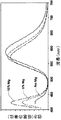
図1は、SPPと、Srの5原子%及び10原子%がMgで置換されているSPPとの発光スペクトルを示す。ブルーシフトが、明確に分かる。 FIG. 1 shows the emission spectra of SPP and SPP in which 5 at% and 10 at% of Sr are substituted by Mg. The blue shift is clearly visible.
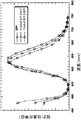
図2は、SPPと、Srの1原子%及び5原子%がMgで置換されているSPPとの発光スペクトルを示す。1原子%に過ぎないMgドーパントが青色発光の実質的な増大を示し始めていることに注目されたい。 FIG. 2 shows emission spectra of SPP and SPP in which 1 atomic% and 5 atomic% of Sr are substituted with Mg. Note that only 1 atomic% Mg dopant is beginning to show a substantial increase in blue emission.
図3は、Sr2P2O7:Eu2+,Mn2+蛍光材料と、Mg、Ba、及びZnでドープされたSr2P2O7:Eu2+,Mn2+蛍光材料との発光スペクトルを示す。Mn2+発光のブルーシフト及びEu2+発光の増大を明らかに見ることができる。 FIG. 3 shows the Sr 2 P 2 O 7 : Eu 2+ , Mn 2+ fluorescent material and the Sr 2 P 2 O 7 : Eu 2+ , Mn 2+ fluorescent material doped with Mg, Ba, and Zn. 3 shows an emission spectrum. The blue shift in Mn 2+ emission and the increase in Eu 2+ emission are clearly visible.
ドープされたSPPを、他の蛍光材料とブレンドして、光度、CRI、及びCCTに関して所望の特性を提供する合成発光スペクトルを作りだすことができる。SPPと共にそのようなブレンドを作るのに好適な蛍光材料には、SAE、BAM、BAMn、SECA、及びMFGが含まれる。本発明の1つの実施形態においては、蛍光材料ブレンドは、例えばMgがドープされたSPPのようなドープされたSPPと、SAE、BAM、BAMn、SECA、及びMFGから成る群から選ばれた少なくとも1つの蛍光材料とを含む。本発明の別の実施形態においては、蛍光材料ブレンドは、ドープされたSPPと、SAEと、BAM、BAMn、SECA、及びMFGから成る群から選ばれた少なくとも1つの蛍光材料とを含む。本発明の別の実施形態においては、蛍光材料ブレンドは、ドープされたSPPと、BAMと、SAE、BAMn、SECA、及びMFGから成る群から選ばれた少なくとも1つの蛍光材料とを含む。本発明の別の実施形態においては、蛍光材料ブレンドは、ドープされたSPPと、SECAと、BAM、BAMn、SAE、及びMFGから成る群から選ばれた少なくとも1つの蛍光材料とを含む。本発明の別の実施形態においては、蛍光材料ブレンドは、ドープされたSPPと、BAMnと、BAM、SAE、SECA、及びMFGから成る群から選ばれた少なくとも1つの蛍光材料とを含む。本発明の別の実施形態においては、蛍光材料ブレンドは、ドープされたSPPと、MFGと、BAM、BAMn、SECA、及びSAEから成る群から選ばれた少なくとも1つの蛍光材料とを含む。これら蛍光材料ブレンドの全ては、約315nmから約480nmまでの範囲の波長を有する電磁放射線を吸収し、かつ可視スペクトルの波長を有する光を放出することができる。 The doped SPP can be blended with other fluorescent materials to create a composite emission spectrum that provides the desired properties with respect to luminosity, CRI, and CCT. Suitable fluorescent materials for making such blends with SPP include SAE, BAM, BAMn, SECA, and MFG. In one embodiment of the present invention, the fluorescent material blend comprises a doped SPP, for example, a Mg-doped SPP, and at least one selected from the group consisting of SAE, BAM, BAMn, SECA, and MFG. And two fluorescent materials. In another embodiment of the present invention, the phosphor blend comprises doped SPP, SAE, and at least one phosphor selected from the group consisting of BAM, BAMn, SECA, and MFG. In another embodiment of the present invention, the phosphor blend comprises doped SPP, BAM, and at least one phosphor selected from the group consisting of SAE, BAMn, SECA, and MFG. In another embodiment of the present invention, the phosphor blend comprises doped SPP, SECA, and at least one phosphor selected from the group consisting of BAM, BAMn, SAE, and MFG. In another embodiment of the present invention, a phosphor blend comprises doped SPP, BAMn, and at least one phosphor selected from the group consisting of BAM, SAE, SECA, and MFG. In another embodiment of the present invention, the phosphor blend comprises doped SPP, MFG, and at least one phosphor selected from the group consisting of BAM, BAMn, SECA, and SAE. All of these fluorescent material blends are capable of absorbing electromagnetic radiation having a wavelength in the range of about 315 nm to about 480 nm and emitting light having wavelengths in the visible spectrum.
これら蛍光材料を適当な割合で混合することによって、最大光度(放射線入力エネルギーのワット当りのルーメン、つまり「lm/Wrad」によって定義されるような)を有する所望のCCT及びCRIを提供する、ブレンドの合成発光スペクトルを作りだすことができる。光源のCCTは、同一色を有する黒体放射体の温度である。白熱電球は、約2000KのCCTを有する。3000Kと5000Kとの間で、光源は真っ白に見える。太陽光は、約5000KのCCTを有する。CCTが8000Kと10000Kとの間まで増大すると、光源は青く見える。試験光源のCRIは、同一温度の標準ランプ下での試験対象物の色と比較した、その試験光源の下での試験対象物について得られた色ずれ(カラーシフト)の度合を示す等級である。CRI値が100の場合、その試験対象物は、それが標準光源によって照らされた場合と同一の色を有すると思われる。蛍光材料ブレンドの組成は、国際照明委員会(「CIE」)の色度図の黒体軌跡に近い座標値を有する白色光の発光を提供するように選ぶことができる。 Mixing these fluorescent materials in appropriate proportions provides the desired CCT and CRI with maximum luminous intensity (lumen per watt of radiation input energy, or as defined by "lm / W rad "). A composite emission spectrum of the blend can be created. The CCT of a light source is the temperature of a blackbody radiator having the same color. Incandescent lamps have a CCT of about 2000K. Between 3000K and 5000K, the light source looks pure white. Sunlight has a CCT of about 5000K. As the CCT increases to between 8000K and 10000K, the light source appears blue. The CRI of a test light source is a rating of the degree of color shift (color shift) obtained for the test object under the test light source compared to the color of the test object under a standard lamp at the same temperature. . If the CRI value is 100, the test object will have the same color as if it were illuminated by a standard light source. The composition of the fluorescent material blend can be selected to provide a white light emission having coordinate values near the blackbody locus of the International Commission on Illumination ("CIE") chromaticity diagram.
ブレンド中の各蛍光材料の量は、蛍光材料の種類及び使用される放射線源の種類によって決まる。個々の蛍光材料は、照明の色、光度、及び演色指数に関して異なった特性を有する。本発明の1つの実施形態においては、ブレンドにおける各蛍光材料のそれぞれの量は、蛍光材料ブレンドからの発光の組合せが人間観察者にとって白く見えるように選ばれる。白色光に加えて、前述の蛍光材料ブレンドを別なように選択することで、他の色の光を発生させることができる。SAE、SECA、BAM、BAMn、及びMFGのような好適な蛍光材料とブレンドされたドープされたSPPは、放出された光の光度が約350lm/Wよりも大きくかつCRIが約60よりも大きくなるような、該ブレンドの合成発光スペクトルを生じる。 The amount of each fluorescent material in the blend depends on the type of fluorescent material and the type of radiation source used. Individual fluorescent materials have different properties with respect to illumination color, luminosity, and color rendering index. In one embodiment of the present invention, the respective amount of each fluorescent material in the blend is selected such that the emission combination from the fluorescent material blend appears white to a human observer. In addition to white light, other colors of light can be generated by differently selecting the aforementioned fluorescent material blend. Doped SPP blended with suitable fluorescent materials, such as SAE, SECA, BAM, BAMn, and MFG, have an emitted light intensity greater than about 350 lm / W and a CRI greater than about 60 Such results in a composite emission spectrum of the blend.
蛍光材料は、任意の従来の固相反応によって作ることができる。例えば、所望の元素の適当量の酸化物及び/又は塩が、互いに十分に混合される。その量は、蛍光材料の所望の最終組成を達成するように選択される。この混合物を、例えば900℃よりも高いような適当な高温で焼成して、酸化物又は塩前駆体を所望の化合物に分解する。この焼成は、蛍光材料に応じて酸化性雰囲気又は還元性雰囲気中で行われる。この焼成は、2つ又はそれ以上の温度段階で行うことができ、各段階は、異なった雰囲気で行うことができる。 The fluorescent material can be made by any conventional solid state reaction. For example, appropriate amounts of oxides and / or salts of the desired elements are thoroughly mixed with each other. The amount is selected to achieve the desired final composition of the fluorescent material. The mixture is calcined at a suitable elevated temperature, for example, above 900 ° C., to decompose the oxide or salt precursor into the desired compound. This firing is performed in an oxidizing atmosphere or a reducing atmosphere depending on the fluorescent material. This calcination can be performed in two or more temperature stages, and each stage can be performed in a different atmosphere.
これに代わる実施形態においては、所望の元素の酸化物及び/又は塩の酸性溶液が、このような酸化物及び/又は塩を無機又は有機酸中に溶解させることによって準備される。選択された元素の化合物を析出させるために、析出が完了するまで水酸化アンモニウム溶液又はアミンがその酸性溶液中にゆっくりと加えられる。一般的に、この段階は、溶液の混合物のpHが約8に上昇すると完了である。析出物は、濾過され、洗浄されて空気中で乾燥される。乾燥された析出物は、上述のように焼成される。 In an alternative embodiment, an acidic solution of an oxide and / or salt of the desired element is prepared by dissolving such an oxide and / or salt in an inorganic or organic acid. Ammonium hydroxide solution or amine is slowly added into the acidic solution until the precipitation is completed to precipitate the compound of the selected element. Generally, this step is complete when the pH of the mixture of solutions rises to about 8. The precipitate is filtered, washed and dried in air. The dried precipitate is fired as described above.
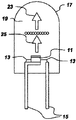
図4に示すように、本発明の1つの実施形態においては、発光ダイオード11は、約315nmから約480nmまでの範囲の近UVから青色までの光を放出する。本発明の別の実施形態においては、発光ダイオード11は、約370nmから約410nmまでの範囲の近UV光を放出する。照明システム100は、発光ダイオードチップ11と、該発光ダイオードチップに対して電気的に取付けられた導線13とを含む。導線13は、厚めの導線フレーム15によって支持された薄いワイヤを含むことができ、或いは、導線は、自己支持式の電極を含み、導線フレームを省略することができる。導線13は、発光ダイオードチップ11に電流を供給し、従って、発光ダイオードチップ11に放射線を放出させることができる。
As shown in FIG. 4, in one embodiment of the present invention,
発光ダイオードチップ11は、該発光ダイオードチップ11と封入材料19とを囲むシェル17内に封入される。本発明の1つの実施形態においては、封入材料19は、耐UVエポキシを含む。シェル17は、例えばガラス又はプラスチックとすることができる。封入材料19は、例えばエポキシ、又はシリコンのような高分子材料とすることができる。発光ダイオードチップ11は、例えば導線フレーム15、自己支持式の電極、シェル17の底部、或いはシェル又は導線フレームに対して取付けられた受台によって、支持されることができる。蛍光材料ブレンド21は、発光ダイオードチップ11の発光表面を覆って、又は直接その上に配置されることができる。シェル17及び封入材料19は、光23がそれら要素を透過することができるように実質的に透明でなければならない。
The light emitting
図5に示すように、本発明の別の実施形態においては、蛍光材料ブレンド21は、発光ダイオードチップ11を覆って配置されるのではなくて、封入材料19内に散在される。蛍光材料ブレンド21は、例えば蛍光材料を高分子前駆体に加え、その後その高分子前駆体を硬化させて高分子材料を固化することによって、封入材料19内に散在させることができる。それに代えて、蛍光材料は、封入材料に加えてもよい。他の蛍光材料散在法も同様に使用することができる。
As shown in FIG. 5, in another embodiment of the present invention, the
図6に示すように、本発明の別の実施形態においては、蛍光材料ブレンド21は、発光ダイオードチップ11を覆って形成されるのではなくて、シェル17上に形成される。本発明の1つの実施形態においては、蛍光材料層は、シェル17の内側表面上に形成されることができるが、蛍光材料層はまた、シェルの外側表面上に形成されてもよい。
As shown in FIG. 6, in another embodiment of the present invention, the
勿論、図4、図5、及び図6は、組合せることができ、蛍光材料は、任意の2箇所又は3箇所全てに、或いは、例えばシェルから切り離された又は発光ダイオード内に一体化されたような任意のその他の好適な箇所に配置することができる。 Of course, FIGS. 4, 5 and 6 can be combined and the fluorescent material can be combined in any two or all three places, for example, separated from the shell or integrated in a light emitting diode And any other suitable location.
本発明の別の実施形態によると、蛍光材料は、蛍光ランプ放射線源を含む白色光照明システム内に配置される。蛍光ランプの一部を、図7に概略的に示している。ランプ31は、蛍光材料のブレンドを含む蛍光材料コーティング35をランプカバー33の表面上、好ましくは内側表面上に含む。本発明の1つの実施形態においては、蛍光ランプ31は、ランプベース37と陰極39とを含む。ランプカバー33は、例えば水銀などのガスを同封し、このガスが、陰極39に印加された電圧に応答して紫外放射線を放出する。
According to another embodiment of the present invention, the fluorescent material is located in a white light illumination system that includes a fluorescent lamp radiation source. A portion of a fluorescent lamp is schematically illustrated in FIG. The
本発明の別の実施形態によると、蛍光材料ブレンドは、プラズマディスプレイ装置を含む白色光照明システム内に配置される。例えばAC又はDCプラズマディスプレイパネルのような任意のプラズマディスプレイ装置を使用することができる。図8は、DCディスプレイ装置41の1つのセルを概略的に示す。このセルは、第1のガラス板42と、第2のガラス板43と、少なくとも1つの陰極44と、少なくとも1つの陽極45と、蛍光材料ブレンドを含む蛍光材料層46と、バリアリブ47と、希ガス空間48とを含む。ACプラズマディスプレイ装置においては、付加的な誘電体層が陰極とガス空間48との間に追加される。陽極45と陰極44との間に電圧を印加することにより、空間48内の希ガスが短波長の真空紫外放射線を放出し、この放射線が、蛍光材料層46を励起して白色光を放出するようになる。
According to another embodiment of the present invention, the fluorescent material blend is located in a white light illumination system that includes a plasma display device. Any plasma display device such as, for example, an AC or DC plasma display panel can be used. FIG. 8 schematically shows one cell of the DC display device 41. The cell includes a
本明細書に記載した高光度蛍光材料ブレンド及び照明システムの用途は、それに限定をするのではないが、例えば夜間の自動車、離着陸間の航空機、押入れ、屋根裏部屋、及び倉庫のような、明かりが十分でない区域を含む。より広い区域をより良好な光度でもって照明するためには、複数のそのような装置が使用される。 Applications of the high intensity phosphor blends and lighting systems described herein include, but are not limited to, lighting, such as night cars, take-off and landing aircraft, closets, attics, and warehouses. Includes areas that are not sufficient. To illuminate a larger area with better luminosity, several such devices are used.
例
8つの蛍光材料ブレンドが、前に説明した従来の固相反応プロセスによって作られた蛍光材料を使用して、又は市販の蛍光材料を使用して準備された。これらブレンドは、約4000Kの相関色温度と座標値x=0.390、y=0.415に近い色点として準備された。下の表1は、ブレンド中の蛍光材料と、指定の色温度、CRI、光度、及び黒体軌跡からの距離を得るために個々の蛍光材料からの発光が果たさなければならない合成スペクトルの割合とを要約している。光度、CRI、黒体軌跡からの距離、及びCIE色座標もまた、表1中に列挙されており、この表において「xxx」は、「存在しない」ことを意味している。
Example 8 Eight fluorescent material blends were prepared using fluorescent materials made by the conventional solid state reaction process described above or using commercially available fluorescent materials. These blends were prepared as correlated color temperatures of about 4000 K and color points near x = 0.390 and y = 0.415. Table 1 below shows the fluorescent materials in the blend and the percentage of the composite spectrum that the emission from each fluorescent material must fulfill to obtain the specified color temperature, CRI, luminosity, and distance from the blackbody locus. Is summarized. Luminous intensity, CRI, distance from blackbody locus, and CIE color coordinates are also listed in Table 1, where "xxx" means "absent".

表1から理解できるように、例7及び例8は、SPP中にドーパント材料を含まない、SPP及びSAEブレンドと、SPP、SECA、及びBAMnブレンドとをそれぞれ示している。例7を例1、例3、及び例5と比較して、SPP中のドーパント材料としての約1重量パーセントのMg、Ba、及びZnのそれぞれの効果を判定することができる。ドーパント材料としてMg、Ba、及びZnを使用することことによる光度の増大が、明確に分かる。例8を例2、例4、及び例6と比較して、SPP中のドーパント材料としての約1重量パーセントのMg、Ba、及びZnのそれぞれの効果を判定することができる。ドーパント材料としてMg、Ba、及びZnを使用することによる光度の増大が、ここでも明確に分かる。 As can be seen from Table 1, Examples 7 and 8 show SPP and SAE blends and SPP, SECA, and BAMn blends, respectively, with no dopant material in the SPP. Example 7 can be compared with Examples 1, 3, and 5 to determine the effect of each of about 1 weight percent Mg, Ba, and Zn as a dopant material in the SPP. The increase in luminosity by using Mg, Ba and Zn as dopant materials is clearly seen. Example 8 can be compared to Examples 2, 4, and 6 to determine the effect of each of about 1 weight percent Mg, Ba, and Zn as a dopant material in the SPP. Again, the increase in luminosity due to the use of Mg, Ba, and Zn as dopant materials is clearly seen here.
図9は、(Sr0.75Eu0.1Mn0.1Mg0.05)2P2O7、BAM、及びBAMnのブレンドの合成発光スペクトルを示す。この発光スペクトルは、ブレンド中の各蛍光材料についての発光スペクトルを合成したものである。 FIG. 9 shows a composite emission spectrum of a blend of (Sr 0.75 Eu 0.1 Mn 0.1 Mg 0.05 ) 2 P 2 O 7 , BAM, and BAMn. This emission spectrum is obtained by synthesizing the emission spectrum of each fluorescent material in the blend.
本明細書において様々な実施形態を説明しているが、要素の様々な組合せ、変更、均等物、又はその改良を当業者が行うことができ、それらは依然として特許請求範囲に記載した本発明の技術的範囲内にあることは、本明細書から明らかであろう。 Although various embodiments are described herein, various combinations, changes, equivalents, or improvements of the elements can be made by those skilled in the art, which are still within the scope of the claimed invention. It will be clear from the present description that it is within the technical scope.
11 発光ダイオードチップ
13 導線
15 導線フレーム
17 シェル
19 封入材料
21 蛍光材料ブレンド
23 光
100 光源
DESCRIPTION OF
Claims (10)
前記第1の蛍光材料が、ストロンチウムがBa、Zn、Ca、及びMgから成る群から選ばれた少なくとも1つの元素によって部分的に置換された、Sr2P2O7:Eu2+,Mn2+を含み、
前記少なくとも第2の蛍光材料が、Sr4Al14O25:Eu2+、(Ba,Sr,Ca)MgAl10O17:Eu2+、(Ba,Sr,Ca)MgAl10O17:Eu2+,Mn2+、(Sr,Ba,Ca,Mg)5(PO4)3Cl:Eu2+、及び3.5MgO・0.5MgF2・GeO2:Mn4+から成る群から選ばれ、
該蛍光材料ブレンドが、約315nmから約480nmまでの範囲の波長を有する電磁放射線を吸収し、かつ可視スペクトルの波長を有する光を放出することができる、
ことを特徴とする蛍光材料ブレンド。 A fluorescent material blend comprising a first fluorescent material and at least a second fluorescent material,
It said first fluorescent material, strontium Ba, Zn, Ca, and was partially substituted by at least one element selected from the group consisting of Mg, Sr 2 P 2 O 7 : Eu 2+, Mn 2 Including + ,
The at least second fluorescent material is Sr 4 Al 14 O 25 : Eu 2+ , (Ba, Sr, Ca) MgAl 10 O 17 : Eu 2+ , (Ba, Sr, Ca) MgAl 10 O 17 : Eu 2 + , Mn 2+ , (Sr, Ba, Ca, Mg) 5 (PO 4 ) 3 Cl: Eu 2+ , and 3.5MgO.0.5MgF 2 .GeO 2 : Mn 4+
The fluorescent material blend is capable of absorbing electromagnetic radiation having a wavelength ranging from about 315 nm to about 480 nm and emitting light having a wavelength in the visible spectrum;
A fluorescent material blend, characterized in that:
前記第1の蛍光材料が、ストロンチウムがBa、Ca、Zn、及びMgから成る群から選ばれた少なくとも1つの元素によって部分的に置換された、Sr2P2O7:Eu2+,Mn2+を含み、
前記第2の蛍光材料が、(Ba,Sr,Ca)MgAl10O17:Eu2+、(Ba,Sr,Ca)MgAl10O17:Eu2+,Mn2+、(Sr,Ba,Ca,Mg)5(PO4)3Cl:Eu2+、及び3.5MgO・0.5MgF2・GeO2:Mn4+から成る群から選ばれ、
前記第3の蛍光材料が、Sr4Al14O25:Eu2+を含み、
該蛍光材料ブレンドが、約315nmから約480nmまでの範囲の波長を有する電磁放射線を吸収し、かつ可視スペクトルの波長を有する光を放出することができる、
ことを特徴とする蛍光材料ブレンド。 A fluorescent material blend including a first fluorescent material, a second fluorescent material, and a third fluorescent material,
Sr 2 P 2 O 7 : Eu 2+ , Mn 2 wherein the first fluorescent material is strontium partially replaced by at least one element selected from the group consisting of Ba, Ca, Zn, and Mg. Including + ,
The second fluorescent material is (Ba, Sr, Ca) MgAl 10 O 17 : Eu 2+ , (Ba, Sr, Ca) MgAl 10 O 17 : Eu 2+ , Mn 2+ , (Sr, Ba, Ca) , Mg) 5 (PO 4 ) 3 Cl: Eu 2+ , and 3.5 MgO · 0.5 MgF 2 • GeO 2 : Mn 4+
The third fluorescent material contains Sr 4 Al 14 O 25 : Eu 2+ ,
The fluorescent material blend is capable of absorbing electromagnetic radiation having a wavelength ranging from about 315 nm to about 480 nm and emitting light having a wavelength in the visible spectrum;
A fluorescent material blend, characterized in that:
前記第1の蛍光材料が、ストロンチウムがBa、Ca、Zn、及びMgから成る群から選ばれた少なくとも1つの元素によって部分的に置換された、Sr2P2O7:Eu2+,Mn2+を含み、
前記第2の蛍光材料が、Sr4Al14O25:Eu2+、(Ba,Sr,Ca)MgAl10O17:Eu2+,Mn2+、(Sr,Ba,Ca,Mg)5(PO4)3Cl:Eu2+、及び3.5MgO・0.5MgF2・GeO2:Mn4+から成る群から選ばれ、
前記第3の蛍光材料が、(Ba,Sr,Ca)MgAl10O17:Eu2+を含み、
該蛍光材料ブレンドが、約315nmから約480nmまでの範囲の波長を有する電磁放射線を吸収し、かつ可視スペクトルの波長を有する光を放出することができる、
ことを特徴とする蛍光材料ブレンド。 A fluorescent material blend including a first fluorescent material, a second fluorescent material, and a third fluorescent material,
Sr 2 P 2 O 7 : Eu 2+ , Mn 2 wherein the first fluorescent material is strontium partially replaced by at least one element selected from the group consisting of Ba, Ca, Zn, and Mg. Including + ,
The second fluorescent material is Sr 4 Al 14 O 25 : Eu 2+ , (Ba, Sr, Ca) MgAl 10 O 17 : Eu 2+ , Mn 2+ , (Sr, Ba, Ca, Mg) 5 ( PO 4 ) 3 Cl: Eu 2+ , and 3.5 MgO.0.5 MgF 2 .GeO 2 : Mn 4+
The third fluorescent material includes (Ba, Sr, Ca) MgAl 10 O 17 : Eu 2+ ,
The fluorescent material blend is capable of absorbing electromagnetic radiation having a wavelength ranging from about 315 nm to about 480 nm and emitting light having a wavelength in the visible spectrum;
A fluorescent material blend, characterized in that:
前記第1の蛍光材料が、ストロンチウムがBa、Ca、Zn、及びMgから成る群から選ばれた少なくとも1つの元素によって部分的に置換された、Sr2P2O7:Eu2+,Mn2+を含み、
前記第2の蛍光材料が、(Ba,Sr,Ca)MgAl10O17:Eu2+、(Ba,Sr,Ca)MgAl10O17:Eu2+,Mn2+、Sr4Al14O25:Eu2+、及び3.5MgO・0.5MgF2・GeO2:Mn4+から成る群から選ばれ、
前記第3の蛍光材料が、(Sr,Ba,Ca,Mg)5(PO4)3Cl:Eu2+を含み、
該蛍光材料ブレンドが、約315nmから約480nmまでの範囲の波長を有する電磁放射線を吸収し、かつ可視スペクトルの波長を有する光を放出することができる、
ことを特徴とする蛍光材料ブレンド。 A fluorescent material blend including a first fluorescent material, a second fluorescent material, and a third fluorescent material,
Sr 2 P 2 O 7 : Eu 2+ , Mn 2 wherein the first fluorescent material is strontium partially replaced by at least one element selected from the group consisting of Ba, Ca, Zn, and Mg. Including + ,
The second fluorescent material is (Ba, Sr, Ca) MgAl 10 O 17 : Eu 2+ , (Ba, Sr, Ca) MgAl 10 O 17 : Eu 2+ , Mn 2+ , Sr 4 Al 14 O 25 : Eu 2+ , and 3.5MgO.0.5MgF 2 .GeO 2 : Mn 4+ , selected from the group consisting of:
The third fluorescent material, (Sr, Ba, Ca, Mg) 5 (PO 4) 3 Cl: includes Eu 2+,
The fluorescent material blend is capable of absorbing electromagnetic radiation having a wavelength ranging from about 315 nm to about 480 nm and emitting light having a wavelength in the visible spectrum;
A fluorescent material blend, characterized in that:
前記第1の蛍光材料が、ストロンチウムがBa、Ca、Zn、及びMgから成る群から選ばれた少なくとも1つの元素によって部分的に置換された、Sr2P2O7:Eu2+,Mn2+を含み、
前記第2の蛍光材料が、(Ba,Sr,Ca)MgAl10O17:Eu2+、Sr4Al14O25:Eu2+、(Sr,Ba,Ca,Mg)5(PO4)3Cl:Eu2+、及び3.5MgO・0.5MgF2・GeO2:Mn4+から成る群から選ばれ、
前記第3の蛍光材料が、(Ba,Sr,Ca)MgAl10O17:Eu2+,Mn2+を含み、
該蛍光材料ブレンドが、約315nmから約480nmまでの範囲の波長を有する電磁放射線を吸収し、かつ可視スペクトルの波長を有する光を放出することができる、
ことを特徴とする蛍光材料ブレンド。 A fluorescent material blend including a first fluorescent material, a second fluorescent material, and a third fluorescent material,
Sr 2 P 2 O 7 : Eu 2+ , Mn 2 wherein the first fluorescent material is strontium partially replaced by at least one element selected from the group consisting of Ba, Ca, Zn, and Mg. Including + ,
The second fluorescent material is (Ba, Sr, Ca) MgAl 10 O 17 : Eu 2+ , Sr 4 Al 14 O 25 : Eu 2+ , (Sr, Ba, Ca, Mg) 5 (PO 4 ) 3 Cl: Eu 2+ , and 3.5 MgO · 0.5 MgF 2 · GeO 2 : selected from the group consisting of Mn 4+ ;
The third fluorescent material contains (Ba, Sr, Ca) MgAl 10 O 17 : Eu 2+ , Mn 2+ ,
The fluorescent material blend is capable of absorbing electromagnetic radiation having a wavelength ranging from about 315 nm to about 480 nm and emitting light having a wavelength in the visible spectrum;
A fluorescent material blend, characterized in that:
前記第1の蛍光材料が、ストロンチウムがBa、Ca、Zn、及びMgから成る群から選ばれた少なくとも1つの元素によって部分的に置換された、Sr2P2O7:Eu2+,Mn2+を含み、
前記第2の蛍光材料が、(Ba,Sr,Ca)MgAl10O17:Eu2+、(Ba,Sr,Ca)MgAl10O17:Eu2+,Mn2+、(Sr,Ba,Ca,Mg)5(PO4)3Cl:Eu2+、及びSr4Al14O25:Eu2+から成る群から選ばれ、
前記第3の蛍光材料が、3.5MgO・0.5MgF2・GeO2:Mn4+を含み、
該蛍光材料ブレンドが、約315nmから約480nmまでの範囲の波長を有する電磁放射線を吸収し、かつ可視スペクトルの波長を有する光を放出することができる、
ことを特徴とする蛍光材料ブレンド。 A fluorescent material blend including a first fluorescent material, a second fluorescent material, and a third fluorescent material,
Sr 2 P 2 O 7 : Eu 2+ , Mn 2 wherein the first fluorescent material is strontium partially replaced by at least one element selected from the group consisting of Ba, Ca, Zn, and Mg. Including + ,
The second fluorescent material is (Ba, Sr, Ca) MgAl 10 O 17 : Eu 2+ , (Ba, Sr, Ca) MgAl 10 O 17 : Eu 2+ , Mn 2+ , (Sr, Ba, Ca) , Mg) 5 (PO 4 ) 3 Cl: Eu 2+ , and Sr 4 Al 14 O 25 : Eu 2+
The third fluorescent material, 3.5MgO · 0.5MgF 2 · GeO 2 : include Mn 4+,
The fluorescent material blend is capable of absorbing electromagnetic radiation having a wavelength ranging from about 315 nm to about 480 nm and emitting light having a wavelength in the visible spectrum;
A fluorescent material blend, characterized in that:
(b)前記発光要素によって放出された前記電磁放射線を受けるように配置された蛍光材料ブレンド(21)と、
を含み、前記蛍光材料ブレンドが、
(1)ストロンチウムがBa、Ca、Zn、及びMgから成る群から選ばれた少なくとも1つの元素によって部分的に置換された、Sr2P2O7:Eu2+,Mn2+を含む第1の蛍光材料と、
(2)Sr4Al14O25:Eu2+、(Ba,Sr,Ca)MgAl10O17:Eu2+、(Ba,Sr,Ca)MgAl10O17:Eu2+,Mn2+、(Sr,Ba,Ca,Mg)5(PO4)3Cl:Eu2+、及び3.5MgO・0.5MgF2・GeO2:Mn4+から成る群から選ばれた少なくとも第2の蛍光材料と、を含み、
約315nmから約480nmまでの範囲の波長を有する電磁放射線を吸収し、かつ可視スペクトルの波長を有する光を放出することができる、
ことを特徴とする光源(100)。 (A) at least one light emitting element (11) capable of emitting electromagnetic radiation having a wavelength in the range from near ultraviolet to blue, selected from the group consisting of light emitting diodes, laser diodes, and gas discharge devices;
(B) a fluorescent material blend (21) arranged to receive the electromagnetic radiation emitted by the light emitting element;
Wherein the fluorescent material blend comprises:
(1) strontium Ba, Ca, Zn, and was partially substituted by at least one element selected from the group consisting of Mg, Sr 2 P 2 O 7 : Eu 2+, first containing Mn 2+ A fluorescent material,
(2) Sr 4 Al 14 O 25 : Eu 2+ , (Ba, Sr, Ca) MgAl 10 O 17 : Eu 2+ , (Ba, Sr, Ca) MgAl 10 O 17 : Eu 2+ , Mn 2+ , At least a second fluorescent material selected from the group consisting of (Sr, Ba, Ca, Mg) 5 (PO 4 ) 3 Cl: Eu 2+ and 3.5MgO.0.5MgF 2 .GeO 2 : Mn 4+ And
Capable of absorbing electromagnetic radiation having a wavelength in the range of about 315 nm to about 480 nm and emitting light having a wavelength in the visible spectrum;
A light source (100), characterized in that:
(b)前記発光要素によって放出された前記電磁放射線を受けるように配置された、第1の蛍光材料と第2の蛍光材料と第3の蛍光材料とを含む蛍光材料ブレンド(21)と、を含み、
前記第1の蛍光材料が、(Sr1-x-y-zEuxMnyMgz)2P2O7:Eu2+,Mn2+を含み、その場合、0<x≦0.1、0<y≦0.1、0<z≦0.05であり、前記第2の蛍光材料が、(Ba,Sr,Ca)MgAl10O17:Eu2+,Mn2+を含み、前記第3の蛍光材料が、(Sr,Ba,Ca,Mg)5(PO4)3Cl:Eu2+を含み、
前記蛍光材料ブレンドが、約315nmから約480nmまでの範囲の波長を有する電磁放射線を吸収し、かつ可視スペクトルの波長を有する光を放出することができる、
ことを特徴とする光源(100)。 (A) at least one light emitting element (11) capable of emitting electromagnetic radiation having a wavelength in the range from near ultraviolet to blue, selected from the group consisting of light emitting diodes, laser diodes, and gas discharge devices;
(B) a fluorescent material blend (21) comprising a first fluorescent material, a second fluorescent material and a third fluorescent material, arranged to receive the electromagnetic radiation emitted by the light emitting element. Including
It said first fluorescent material, (Sr 1-xyz Eu x Mn y Mg z) 2 P 2 O 7: Eu 2+, comprises Mn 2+, in which case, 0 <x ≦ 0.1,0 <y ≦ 0.1, 0 <z ≦ 0.05, the second fluorescent material contains (Ba, Sr, Ca) MgAl 10 O 17 : Eu 2+ , Mn 2+ , and the third fluorescent material material, (Sr, Ba, Ca, Mg) 5 (PO 4) 3 Cl: includes Eu 2+,
The fluorescent material blend is capable of absorbing electromagnetic radiation having a wavelength ranging from about 315 nm to about 480 nm and emitting light having a wavelength in the visible spectrum;
A light source (100), characterized in that:
Applications Claiming Priority (1)
| Application Number | Priority Date | Filing Date | Title |
|---|---|---|---|
| US10/356,163 US6844671B2 (en) | 2003-01-31 | 2003-01-31 | High luminosity phosphor blends for generating white light from near-UV/blue light-emitting devices |
Publications (2)
| Publication Number | Publication Date |
|---|---|
| JP2004231966A true JP2004231966A (en) | 2004-08-19 |
| JP3975298B2 JP3975298B2 (en) | 2007-09-12 |
Family
ID=32770727
Family Applications (1)
| Application Number | Title | Priority Date | Filing Date |
|---|---|---|---|
| JP2004022389A Expired - Fee Related JP3975298B2 (en) | 2003-01-31 | 2004-01-30 | High intensity fluorescent material blend for generating white light from near ultraviolet / blue light emitting devices |
Country Status (2)
| Country | Link |
|---|---|
| US (1) | US6844671B2 (en) |
| JP (1) | JP3975298B2 (en) |
Cited By (5)
| Publication number | Priority date | Publication date | Assignee | Title |
|---|---|---|---|---|
| CZ308769B6 (en) * | 2020-03-17 | 2021-05-05 | Crytur, Spol. S.R.O. | Compact light module |
| US12310921B2 (en) | 2020-07-21 | 2025-05-27 | Icu Medical, Inc. | Fluid transfer devices and methods of use |
| US12333201B2 (en) | 2017-12-27 | 2025-06-17 | Icu Medical, Inc. | Synchronized display of screen content on networked devices |
| US12346879B2 (en) | 2011-08-19 | 2025-07-01 | Icu Medical, Inc. | Systems and methods for a graphical interface including a graphical representation of medical data |
| US12350233B2 (en) | 2021-12-10 | 2025-07-08 | Icu Medical, Inc. | Medical fluid compounding systems with coordinated flow control |
Families Citing this family (18)
| Publication number | Priority date | Publication date | Assignee | Title |
|---|---|---|---|---|
| US6501100B1 (en) * | 2000-05-15 | 2002-12-31 | General Electric Company | White light emitting phosphor blend for LED devices |
| DE10326755A1 (en) * | 2003-06-13 | 2006-01-26 | Patent-Treuhand-Gesellschaft für elektrische Glühlampen mbH | Discharge lamp with dual band phosphor |
| US7327078B2 (en) * | 2004-03-30 | 2008-02-05 | Lumination Llc | LED illumination device with layered phosphor pattern |
| TWI242893B (en) * | 2004-05-07 | 2005-11-01 | Lite On Technology Corp | White light-emitting apparatus |
| CN101562227B (en) * | 2005-05-30 | 2010-12-08 | 夏普株式会社 | Light emitting device and method of manufacturing the same |
| US8333907B2 (en) | 2007-01-17 | 2012-12-18 | Utc Fire & Security Corporation | Articles using persistent phosphors |
| US7959827B2 (en) * | 2007-12-12 | 2011-06-14 | General Electric Company | Persistent phosphor |
| US7608829B2 (en) * | 2007-03-26 | 2009-10-27 | General Electric Company | Polymeric composite scintillators and method for making same |
| US7625502B2 (en) * | 2007-03-26 | 2009-12-01 | General Electric Company | Nano-scale metal halide scintillation materials and methods for making same |
| US7708968B2 (en) * | 2007-03-26 | 2010-05-04 | General Electric Company | Nano-scale metal oxide, oxyhalide and oxysulfide scintillation materials and methods for making same |
| US8545723B2 (en) * | 2007-12-12 | 2013-10-01 | General Electric Company | Persistent phosphor |
| US7955875B2 (en) * | 2008-09-26 | 2011-06-07 | Cree, Inc. | Forming light emitting devices including custom wavelength conversion structures |
| US8329060B2 (en) * | 2008-10-22 | 2012-12-11 | General Electric Company | Blue-green and green phosphors for lighting applications |
| US8703016B2 (en) | 2008-10-22 | 2014-04-22 | General Electric Company | Phosphor materials and related devices |
| TWI456027B (en) * | 2010-03-03 | 2014-10-11 | Hitachi Ltd | Closed material sheet with wavelength conversion material and solar cell using the same |
| US9337010B2 (en) | 2014-09-05 | 2016-05-10 | Lawrence Livermore National Security, Llc | Fluorescent lighting with aluminum nitride phosphors |
| CN108410452B (en) * | 2017-02-09 | 2021-03-19 | 有研稀土新材料股份有限公司 | Light-emitting material composition and light-emitting device |
| EP4379825A4 (en) * | 2021-07-29 | 2024-11-06 | Panasonic Intellectual Property Management Co., Ltd. | ELECTROLUMINESCENT DEVICE AND ELECTRONIC APPARATUS |
Family Cites Families (5)
| Publication number | Priority date | Publication date | Assignee | Title |
|---|---|---|---|---|
| US5777350A (en) | 1994-12-02 | 1998-07-07 | Nichia Chemical Industries, Ltd. | Nitride semiconductor light-emitting device |
| US6621211B1 (en) * | 2000-05-15 | 2003-09-16 | General Electric Company | White light emitting phosphor blends for LED devices |
| US6501100B1 (en) * | 2000-05-15 | 2002-12-31 | General Electric Company | White light emitting phosphor blend for LED devices |
| US6685852B2 (en) * | 2001-04-27 | 2004-02-03 | General Electric Company | Phosphor blends for generating white light from near-UV/blue light-emitting devices |
| US6903505B2 (en) * | 2001-12-17 | 2005-06-07 | General Electric Company | Light-emitting device with organic electroluminescent material and photoluminescent materials |
-
2003
- 2003-01-31 US US10/356,163 patent/US6844671B2/en not_active Expired - Fee Related
-
2004
- 2004-01-30 JP JP2004022389A patent/JP3975298B2/en not_active Expired - Fee Related
Cited By (5)
| Publication number | Priority date | Publication date | Assignee | Title |
|---|---|---|---|---|
| US12346879B2 (en) | 2011-08-19 | 2025-07-01 | Icu Medical, Inc. | Systems and methods for a graphical interface including a graphical representation of medical data |
| US12333201B2 (en) | 2017-12-27 | 2025-06-17 | Icu Medical, Inc. | Synchronized display of screen content on networked devices |
| CZ308769B6 (en) * | 2020-03-17 | 2021-05-05 | Crytur, Spol. S.R.O. | Compact light module |
| US12310921B2 (en) | 2020-07-21 | 2025-05-27 | Icu Medical, Inc. | Fluid transfer devices and methods of use |
| US12350233B2 (en) | 2021-12-10 | 2025-07-08 | Icu Medical, Inc. | Medical fluid compounding systems with coordinated flow control |
Also Published As
| Publication number | Publication date |
|---|---|
| US6844671B2 (en) | 2005-01-18 |
| JP3975298B2 (en) | 2007-09-12 |
| US20040150316A1 (en) | 2004-08-05 |
Similar Documents
| Publication | Publication Date | Title |
|---|---|---|
| JP3975298B2 (en) | High intensity fluorescent material blend for generating white light from near ultraviolet / blue light emitting devices | |
| US6685852B2 (en) | Phosphor blends for generating white light from near-UV/blue light-emitting devices | |
| US6621211B1 (en) | White light emitting phosphor blends for LED devices | |
| US7077978B2 (en) | Phosphors containing oxides of alkaline-earth and group-IIIB metals and white-light sources incorporating same | |
| US7015510B2 (en) | White light emitting phosphor blend for LED devices | |
| CN100530708C (en) | Phosphor for LED and mixture thereof | |
| WO2005033247A1 (en) | Oxynitride phosphor and light-emitting device | |
| JP2004269845A (en) | Blue-green phosphor for fluorescent lighting | |
| JP4836229B2 (en) | Phosphor and light emitting device | |
| JP2016176017A (en) | Phosphor and light emitting device using the same | |
| JP4309242B2 (en) | Red phosphor material, white light emitting diode using red phosphor material, and lighting device using white light emitting diode | |
| JP2008500422A (en) | Low pressure mercury vapor discharge lamp with UV-A phosphor | |
| JP2015221843A (en) | Phosphor and light emitting device using the same | |
| KR101072572B1 (en) | Red phosphor and its forming method for use in solid state lighting | |
| US8362689B2 (en) | Phosphors and light-emitting devices using the same | |
| JP3754701B2 (en) | Phosphor and light emitting device using the same | |
| CN101743613A (en) | Discharge lamp and illuminant compound for a discharge lamp | |
| JP5521247B2 (en) | Phosphor and light emitting device | |
| JP6099089B2 (en) | Oxynitride phosphor and light emitting device | |
| KR20050027986A (en) | Yellow light-emitting halophosphate phosphors and light sources incorporating the same |
Legal Events
| Date | Code | Title | Description |
|---|---|---|---|
| A621 | Written request for application examination |
Free format text: JAPANESE INTERMEDIATE CODE: A621 Effective date: 20070126 |
|
| A871 | Explanation of circumstances concerning accelerated examination |
Free format text: JAPANESE INTERMEDIATE CODE: A871 Effective date: 20070126 |
|
| A975 | Report on accelerated examination |
Free format text: JAPANESE INTERMEDIATE CODE: A971005 Effective date: 20070219 |
|
| A131 | Notification of reasons for refusal |
Free format text: JAPANESE INTERMEDIATE CODE: A131 Effective date: 20070227 |
|
| A521 | Request for written amendment filed |
Free format text: JAPANESE INTERMEDIATE CODE: A523 Effective date: 20070406 |
|
| TRDD | Decision of grant or rejection written | ||
| A01 | Written decision to grant a patent or to grant a registration (utility model) |
Free format text: JAPANESE INTERMEDIATE CODE: A01 Effective date: 20070508 |
|
| A61 | First payment of annual fees (during grant procedure) |
Free format text: JAPANESE INTERMEDIATE CODE: A61 Effective date: 20070604 |
|
| FPAY | Renewal fee payment (event date is renewal date of database) |
Free format text: PAYMENT UNTIL: 20100629 Year of fee payment: 3 |
|
| R150 | Certificate of patent or registration of utility model |
Free format text: JAPANESE INTERMEDIATE CODE: R150 |
|
| FPAY | Renewal fee payment (event date is renewal date of database) |
Free format text: PAYMENT UNTIL: 20100629 Year of fee payment: 3 |
|
| FPAY | Renewal fee payment (event date is renewal date of database) |
Free format text: PAYMENT UNTIL: 20110629 Year of fee payment: 4 |
|
| FPAY | Renewal fee payment (event date is renewal date of database) |
Free format text: PAYMENT UNTIL: 20120629 Year of fee payment: 5 |
|
| FPAY | Renewal fee payment (event date is renewal date of database) |
Free format text: PAYMENT UNTIL: 20130629 Year of fee payment: 6 |
|
| LAPS | Cancellation because of no payment of annual fees |