JP2004232000A - Cemented carbide, method of manufacturing the same, and rotary tool using the cemented carbide - Google Patents
Cemented carbide, method of manufacturing the same, and rotary tool using the cemented carbide Download PDFInfo
- Publication number
- JP2004232000A JP2004232000A JP2003019541A JP2003019541A JP2004232000A JP 2004232000 A JP2004232000 A JP 2004232000A JP 2003019541 A JP2003019541 A JP 2003019541A JP 2003019541 A JP2003019541 A JP 2003019541A JP 2004232000 A JP2004232000 A JP 2004232000A
- Authority
- JP
- Japan
- Prior art keywords
- cemented carbide
- particles
- average particle
- particle size
- powder
- Prior art date
- Legal status (The legal status is an assumption and is not a legal conclusion. Google has not performed a legal analysis and makes no representation as to the accuracy of the status listed.)
- Granted
Links
Images
Landscapes
- Drilling Tools (AREA)
- Powder Metallurgy (AREA)
Abstract
Description
【0001】
【発明の属する技術分野】
本発明は、切削工具等に使用される高強度かつ高靭性を有し、プリント基板穴開け用のマイクロドリル等においても、耐折損性、耐摩耗性に優れ高精度で長寿命の穴開けが可能な優れた性能を発揮する超硬合金およびその製造方法、並びにその超硬合金を用いた回転工具に関する。
【0002】
【従来の技術】
従来より、金属の切削加工に広く用いられている超硬合金は、六方晶形からなり、断面が三角形や四角形等の多角形形状をなす角ばったWC粒子を主体とする硬質相と、Co等の鉄族金属の結合相からなるWC−Co系合金、もしくは上記WC−Co系に周期律表第4a、5a、6a族金属の炭化物、窒化物、炭窒化物等の固溶体相を分散せしめた系が知られている。
【0003】
これらの超硬合金は、切削工具として、主に鋳鉄や炭素鋼等の切削に利用されているが、最近ではステンレス鋼といった難削材の加工やプリント基板の小径穴あけ加工等、切削の更なる効率化を求めて高速切削・高送り切削への利用も進められている。
【0004】
一方、プリント基板加工用の素材としては、Cr(クロム)やV(バナジウム)等の粒成長抑制剤を添加したWC粒子の粒径が1μmより小さい、いわゆる超微粒超硬合金が主として用いられ、高硬度、高強度であることを活かして、耐欠損性および耐摩耗性に優れ、かつ穴位置精度の高いドリルが公用されている。
【0005】
かかるプリント基板加工用のドリルについては、最近、プリント基板の高密度化に伴って加工される穴径が微細化する傾向にあり、ドリル径も小径化することが要求されている。
【0006】
【発明が解決しようとする課題】
しかしながら、上記従来の超微粒超硬合金では、ドリル径が小径化するにしたがってドリルの強度が低下し、ドリル先端の刃先が摩耗する前にドリルの根元から折損する結果、安定して穴開けできる加工数が減じ工具寿命が短くなり頻繁にドリル交換をしなければならないという問題があった。
【0007】
したがって、本発明の目的は、小径ドリル等に用いる場合においても耐折損性に優れた超硬合金を提供すること、かつこれを用いて、小径の穴あけ加工や高送り切削に対しても優れた耐折損性を有する回転工具を提供することにある。
【0008】
【課題を解決するための手段】
本発明者は、上記課題に対して検討した結果、平均粒径が0.5μm以下のWC粒子とコバルトからなる超硬合金中に、TaおよびCrを添加、含有せしめての所定条件で焼成することによって、WC粒子が角部のない丸みのある形状となりやすく、この微粒で丸いWC粒子を所定量超硬合金中に分散せしめた組織とすることによって、合金中に衝撃がかかった際WC粒子の角部に応力が集中して角部にクラックが生じ、折損してしまうことなく耐折損性に優れた超硬合金となることを知見した。
【0009】
すなわち、本発明の超硬合金は、平均粒径が0.5μm以下のWC粒子間を鉄属金属を主体とする結合相にて結合するとともに、TaおよびCrを含有してなる超硬合金であって、該超硬合金の透過型電子顕微鏡観察において、前記WC粒子が概略多角形形状で、かつ、長径に対してなす2つの角部の曲率半径が50nm以上の丸みを呈する粒子の数が粒子全体に対して50面積%以上の割合で含まれていることを特徴とするものである。
【0010】
ここで、前記TaおよびCrの含有量が前記超硬合金総量に対して0.7〜3質量%であることにより、超硬合金中に前記丸いWC粒子を上記所定の割合で含有せしめることができる。
【0011】
また、平均粒径0.2μm以下のTaC粒子を含むこと、前記超硬合金の走査型電子顕微鏡観察において、前記TaC粒子の面積が前記超硬合金全体の面積に対して0.1〜3体積%の割合で分散していることによって、超硬合金の高温特性を維持することができる。
【0012】
さらに、前記該超硬合金を粉砕し、#20メッシュを通した粉砕粉末を50℃の希塩酸(HCl:H2O=1:1)中で24時間溶解してろ過したろ液中に、W、TaおよびCrの総量が3〜30質量%の割合で含まれていることによって、結合相の硬度を高めて、超硬合金全体としての硬度および強度を高めることができる。
【0013】
さらに、本発明の超硬合金の製造方法は、平均粒径0.05〜0.5μmのWC粉末と、平均粒径0.1〜0.8μmの金属Co粉末と、平均粒径0.1〜1μmのTaC粉末と、平均粒径0.3〜1μmのCr3C2粉末と、溶媒とを混合し、成形後、1380〜1430℃で0.5〜1時間真空焼成し、該焼成温度よりも5〜30℃低い温度で0.5〜1時間SinterHIPして3〜6℃/minにて冷却することを特徴とする。
【0014】
また、上記記載の超硬合金からなる回転工具は耐欠損性、耐摩耗性に優れるとともに、小径化しても耐折損性が高く、微細で高精度な穴を長寿命に加工できるものである。
【0015】
【発明の実施の形態】
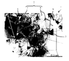
本発明の超硬合金について、その内部の透過型電子顕微鏡写真である図1を基に説明する。
図1によれば、超硬合金1は、WC相2と、少なくとも1種の鉄属金属を主成分として含有する結合相5とから構成されている。
【0016】
本発明によれば、超硬合金1内部断面の透過型電子顕微鏡観察において、WC粒子を平均粒径0.5μm以下、特に0.1〜0.4μm、さらに0.2〜0.3μmの概略多角形形状とすることにより、超硬合金1の硬度を向上させることができ、耐摩耗性の高いドリルとなる。また、長径(WC粒子の外周2点間の最大長さ)に対してなす2つの角部の曲率半径r1、r2の平均値が50nm以上、特に70nm以上、さらには0.1μm以上の丸みを呈する粒子(以下、角部が丸い粒子と略す。)8がWC粒子2全体に対して50体積%以上、特に70体積%以上、さらに80体積%以上であることが大きな特徴であり、これによって超硬合金1の抗折強度を高めることができ、さらに耐折損性の優れた回転工具となる。
【0017】
ここで、角部が丸い粒子8は、前記角部の曲率半径が0.1μm以上である粒子がWC粒子2全体に対して20体積%以上、特に30体積%以上、さらに50体積%以上であることが超硬合金1の耐折損性を高める上で望ましい。
【0018】
また、WC粒子2のうち、長径に対してなす2つの角部の曲率半径が50nm以上の丸みを呈する角部が丸い粒子8がWC粒子2全体に対して50体積%より少ないと、長径に対してなす2つの角部の曲率半径が50nm以下の先端部からなる角部が鋭利なWC粒子(以下、角状粒子と呼ぶ)での応力集中が起こりやすく、切削中にクラックの起点となり折損を生じやすくなり超硬合金1の耐折損性が低下する恐れがある。
【0019】
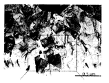
なお、本発明において、図2に示すように長径とは超硬合金1の内部断面の透過型電子顕微鏡観察において、WC粒子2の内部に引き得る最も長い線分Lの長さ(2点間最大長さ)を指し、また、長径に対してなす2つの角部の曲率半径とは、上記線分Lの端部、すなわち2つの角部におけるそれぞれの曲率半径rの平均値を指す。ここで、該曲率半径rが50nmより小さくなると急激に耐折損性が低下する。
【0020】
また、本発明によれば、超硬合金1中にCrとTaをともに含有することが重要であり、これによって、WC粒子2のうち、長径に対してなす2つの角部の曲率半径が50nm以上の丸みを呈する角部が丸い粒子8の割合をWC粒子2全体に対して50体積%以上とすることができる。すなわち、CrおよびTaのいずれかが所定の範囲から外れると所定の丸みを呈するWC粒子の割合が50体積%より少なくなって直径が0.2mmφ以下の極小径ドリルについての耐折損性が低下してしまう。なお、CrとTaとの望ましい含有割合はWC粒子2の形状を制御し、かつ合金1の強度を損なわない点で、Crを0.2〜1.5質量%、Taを0.5〜1.5質量%である。
【0021】
また、本発明によれば、超硬合金1中にTaC粒子3が存在することが、超硬合金1の高温特性、特に高温における耐酸化性を維持する点で望ましく、またTaC粒子3はB−1型であるため結晶は粒状になり、本発明における応力集中による耐折損性の低下は起こしにくいが、TaC粒子3が破壊源となり、合金1の強度が低下して耐折損性が低下することを防ぐため、TaC粒子3の平均粒径は0.01〜0.2μm、特に0.03〜0.1μmであることが望ましい。
【0022】
また、TaC粒子3の含有量は、高温における耐酸化性と超硬合金1の強度および硬度を両立させるという点で、超硬合金1の任意5箇所においての走査型電子顕微鏡観察の面積比率で0.1〜3面積%、特に0.3〜1面積%であることが望ましい。なお、走査型電子顕微鏡観察における面積比率は公知の画像解析法を用いて行うことができる。
【0023】
さらに、結合相5の硬度を高めて、合金1全体の硬度および強度を高めるために、前記該超硬合金を粉砕し、#20メッシュを通した粉砕粉末を50℃の希塩酸(HCl:H2O=1:1)中で24時間溶解してろ過したろ液中に、W、TaおよびCrの総量が3〜30質量%の割合で含まれていることが望ましい。
【0024】
前記ろ液中には超硬合金の炭化タングステン粒子以外の大部分が含まれ、すなわち、主として結合相が含まれ、また、炭化タングステン粒子の結合相との界面部および第3相の一部または全部が溶出したものが含まれる。本発明によれば、結合相および炭化タングステン粒子や第3相の硬質相の界面部分に所定量のW、TaおよびCrを含有せしめることにより、超硬合金の硬度と抗折力とを両立させて、加工時の工具の寿命を高めることができる。
【0025】
(製造方法)
また、上述した超硬合金を製造するには、まず、例えば平均粒径0.05〜0.7μmの炭化タングステン粉末を80〜90質量%、平均粒径0.1〜2μmのTaC粉末を0.5〜2質量%、平均粒径0.1〜2μmのCr3C2粉末を0.2〜1質量%、平均粒径0.5〜1μmの鉄族金属を5〜15質量%、さらには所望により、金属タングステン(W)粉末、あるいはカーボンブラック(C)を混合する。
【0026】
本発明によれば、上記原料組成とともに、上記混合に際して、メタノール等の有機溶媒を加え、粉砕メディアとして平均粒径が2〜6μmの超硬合金からなるボールを用いて、50〜80時間振動ミル粉砕すること、あるいは40〜60時間アトライタ粉砕することが重要であり、さらに後述する工程を経ることによって、上述した所定の大きさを有するとともに、角の丸い粒子を所定量分散させることができる。
【0027】
次に、上記混合粉末を用いて、プレス成形、鋳込成形、押出成形、冷間静水圧プレス成形等の公知の成形方法によって所定形状に成形した後、1380〜1430℃で0.5〜1時間真空焼成し、該焼成温度よりも5〜100℃低い温度で0.5〜1時間熱間静水圧プレス処理をして3〜6℃/minにて冷却することにより上述した超硬合金を得ることができる。
【0028】
ここで、上記工程のうち、焼成温度が1380℃より低いと超硬合金の焼結性が低下してしまい、逆に焼成温度が1430℃より高いと炭化タングステン粒子が粒成長してしまい強度が低下する。さらに、SinterHIP温度が最高保持温度より5℃以上低くないと焼結が進行しすぎて、合金のヤング率および抗磁力が高くなりすぎてドリルが早期に折損しやすくなり、逆にSinterHIP温度が最高保持温度と比較して100℃より低いと焼結性が低下してドリル寿命が低下する。
【0029】
また、上述した本発明の超硬合金は、高硬度、高強度に優れるとともに、優れた耐折損性を有することから、回転工具、特にプリント基板加工用ドリルとして好適に使用可能である。
【0030】
また、本発明の切削工具は、上述した超硬合金の表面に、周期律表第4a、5a、6a族金属の炭化物、窒化物、炭窒化物、TiAlN、TiZrN、ダイヤモンドおよびAl2O3の群から選ばれる少なくとも1種の被覆層を単層または複数層形成したものであってもよい。
【0031】
なお、超硬合金に前記被覆層を形成するには、所望により、超硬合金の表面を研磨、洗浄した後、従来公知のPVD法やCVD法等の薄膜形成法を用いればよい。また、被覆層の厚みは0.1〜20μmであることが望ましい。
【0032】
また、上記超硬合金を用いてプリント基板加工用ドリルを作製するには、上述した原料および成形用混合粉末を用いて棒状成形体を作製し、上述した焼成方法に従って焼成した後、焼結体に加工を施して所望のドリル形状に加工することによって作製できる。さらに、ドリルの少なくとも一部に上述したコーティング膜を成膜してもよい。
【0033】
【実施例】
(実施例)
表1に示す平均粒径の炭化タングステン(WC)粉末、平均粒径0.6μmの金属コバルト(Co)粉末および平均粒径1.0μmのTaC粉末、平均粒径1.1μmのCr3C2粉末、平均粒径0.5μmのVC粒子を表1に示す比率で添加し、溶媒としてメタノールを、メディアとしてメディア径4mmでWC粒子の平均粒径0.3μmの超硬合金製ボールを加えて、68時間振動ミル混合し、混合粉末を作製した後、有機バインダとしてパラフィンワックス1.6質量%添加し、金型プレス成形し、表1に示す条件で真空焼成およびそれに引き続いてsinterHIP処理して超硬合金を50本ずつ作製した。
【0034】
なお、焼成温度までの昇温速度:5℃/min、焼成時間:1時間、熱間静水圧処理の条件はアルゴン圧力6MPa、時間:0.5時間で一定とした。また、表中、真空焼成温度とsinterHIP温度との温度差をΔT(℃)、sinterHIP後の冷却速度を冷却速度と表記した。
【0035】
【表1】

得られた超硬合金の任意断面5箇所について、透過型電子顕微鏡により図1に示すような64000倍の反射電子像を観察し、2μm×2μmの任意領域について、WC粒子の形状(WC粒子の平均粒径、WC粒子の長径をなす線分Lの角部について曲率半径50nm以上の丸い粒子の比率)を測定し、また、WC粒子および結合相の含有面積比率、固溶体相の平均粒径をルーゼックス画像解析法によって算出した。結果を表2に示す。
【0037】
また、前記超硬合金について、2枚刃形状のドリル形状に加工し、下記条件によってプリント基板の孔あけ加工テストを行い、試料が折損するまでの加工穴数を測定した。
<条件>
被削材 :FR4・6層板、1.6mm厚、3枚重ね
ドリル形状:φ0.15mmアンダーカットタイプ
回転数:120kr.p.m.
送り速度:2.4m/min.
【0038】
【表2】
表1,2の結果より、CrとTaをともには添加しない試料No.6,7は、WC粒子中、角部が丸い粒子の割合が50体積%より少なくほとんどが角ばった形状からなり、耐折損性が低下した。また、焼成温度が1430℃を超える試料No.4およびsinterHIP後の冷却速度が3℃/分より遅い試料No.8でもWC粒子中、角部が丸い粒子の割合が50体積%より少なくほとんどが角ばった形状からなり、耐折損性が低下した。
【0040】
これに対して、本発明に従い、CrとTaをともに添加するとともに所定の条件にて製造した試料No.1〜3では、いずれもWC粒子中、角部が丸い粒子の割合が50体積%より高くなり、かつ極小径である直径が0.15mmφのドリルについての穴開け試験にて加工穴数2000穴以上の優れた耐折損性を示すものであった。
【0041】
【発明の効果】
以上詳述したとおり、本発明の超硬合金によれば、WC粒子の平均粒径を0.5μm以下とし、かつ、角部のない丸みのあるWC粒子を所定量超硬合金中に分散せしめた組織とすることによって、衝撃がかかった際でも角部にクラックが生じることなく、衝撃を粒子全体で吸収することができることから、耐折損性に優れた超硬合金となり、これを回転工具として用いることによって、小径穴あけ加工や高送り切削等の過酷な切削条件に対しても優れた耐折損性を有する回転工具を得ることができる。
【0042】
また、本発明の超硬合金の製造方法によれば、平均粒径0.05〜0.5μmのWC粉末と、平均粒径0.1〜0.8μmの金属Co粉末と、平均粒径0.1〜1μmのTaC粉末と、平均粒径0.3〜1μmのCr3C2粉末と、溶媒とを混合し、成形後、1380〜1430℃で0.5〜1時間真空焼成し、該焼成温度よりも5〜30℃低い温度で0.5〜1時間SinterHIPして3〜6℃/minにて冷却することから、角部のない丸みのあるWC粒子を所定量超硬合金中に分散せしめた組織とすることができ、もって衝撃がかかった際でも角部にクラックが生じることなく、衝撃を粒子全体で吸収することができることから、耐折損性に優れた超硬合金を製造することができる。
【図面の簡単な説明】
【図1】本発明のプリント基板加工用超硬合金の一例を示す図面代用透過電子顕微鏡写真である。
【図2】従来のプリント基板加工用超硬合金の一例を示す図面代用透過電子顕微鏡写真である。
【符号の説明】
1:超硬合金
2:炭化タングステン粒子
3:TaC粒子
5:結合相
7:角状粗粒子
8:角部が丸い粒子
9:角部
L:長径2μm以上の炭化タングステン粒子の内部に引きうる最も長い線分
r:線分Lに対してなす角部の曲率半径[0001]
TECHNICAL FIELD OF THE INVENTION
The present invention has high strength and high toughness used for cutting tools and the like, and also has excellent breakage resistance, wear resistance, and high precision and long life drilling even in micro drills for drilling printed circuit boards. The present invention relates to a cemented carbide exhibiting possible and excellent performance, a method for producing the same, and a rotary tool using the cemented carbide.
[0002]
[Prior art]
Conventionally, cemented carbides widely used for metal cutting are composed of hexagonal, and have a hard phase mainly composed of angular WC particles having a polygonal shape such as a triangle or a quadrangle in cross section, and Co or the like. WC-Co-based alloy composed of a bonded phase of an iron group metal, or a system in which a solid solution phase such as a carbide, nitride or carbonitride of a Group 4a, 5a or 6a metal of the periodic table is dispersed in the WC-Co system. It has been known.
[0003]
These cemented carbides are mainly used as cutting tools for cutting cast iron and carbon steel. Recently, however, they have been used for cutting difficult-to-cut materials such as stainless steel and drilling small holes in printed circuit boards. Use for high-speed cutting and high-feed cutting is also being pursued in order to increase efficiency.
[0004]
On the other hand, as a material for processing a printed circuit board, a so-called ultrafine-grained cemented carbide in which a WC particle added with a grain growth inhibitor such as Cr (chromium) or V (vanadium) is smaller than 1 μm is mainly used, Utilizing high hardness and high strength, drills having excellent fracture resistance and wear resistance and high hole position accuracy are used in public.
[0005]
With regard to such a drill for processing a printed circuit board, recently, the hole diameter to be processed tends to be reduced in accordance with the increase in the density of the printed circuit board, and it is required to reduce the drill diameter.
[0006]
[Problems to be solved by the invention]
However, in the conventional ultrafine-grained cemented carbide described above, the strength of the drill decreases as the diameter of the drill decreases, and as a result, the drill is broken from the root of the drill before the edge of the drill is worn, so that the hole can be stably drilled. There has been a problem that the number of machining operations is reduced, the tool life is shortened, and frequent drill replacement is required.
[0007]
Therefore, an object of the present invention is to provide a cemented carbide having excellent breakage resistance even when used in a small-diameter drill or the like, and is also excellent in small-diameter drilling or high-feed cutting using the same. An object of the present invention is to provide a rotary tool having breakage resistance.
[0008]
[Means for Solving the Problems]
As a result of studying the above problem, the present inventor has found that, in a cemented carbide consisting of WC particles having an average particle diameter of 0.5 μm or less and cobalt, Ta and Cr are added and sintered under predetermined conditions. As a result, the WC particles tend to have a rounded shape without corners, and by forming a structure in which a predetermined amount of the round WC particles are dispersed in a cemented carbide, the WC particles are subjected to an impact in the alloy. It has been found that stress concentrates on the corners of the alloy and cracks occur at the corners, and the cemented carbide is excellent in breakage resistance without being broken.
[0009]
That is, the cemented carbide of the present invention is a cemented carbide containing WC particles having an average particle diameter of 0.5 μm or less with a binder phase mainly composed of an iron group metal and containing Ta and Cr. In a transmission electron microscope observation of the cemented carbide, the number of particles in which the WC particles have a substantially polygonal shape and a radius of curvature of two corners with respect to the major axis is 50 nm or more is round. It is characterized in that it is contained in a proportion of 50% by area or more with respect to the whole particles.
[0010]
Here, when the content of the Ta and Cr is 0.7 to 3% by mass based on the total amount of the cemented carbide, the round WC particles can be contained in the cemented carbide at the above-described predetermined ratio. it can.
[0011]
Further, it contains TaC particles having an average particle diameter of 0.2 μm or less, and in observation of the cemented carbide with a scanning electron microscope, the area of the TaC particles is 0.1 to 3 vol. %, The high-temperature characteristics of the cemented carbide can be maintained.
[0012]
Further, the cemented carbide was pulverized, and the pulverized powder passed through # 20 mesh was dissolved in dilute hydrochloric acid (HCl: H 2 O = 1: 1) at 50 ° C. for 24 hours. , Ta and Cr are contained at a ratio of 3 to 30% by mass, whereby the hardness of the binder phase can be increased, and the hardness and strength of the cemented carbide as a whole can be increased.
[0013]
Furthermore, the method for producing a cemented carbide according to the present invention comprises the steps of: WC powder having an average particle size of 0.05 to 0.5 μm, metal Co powder having an average particle size of 0.1 to 0.8 μm, 11 μm TaC powder, Cr 3 C 2 powder having an average particle diameter of 0.3-1 μm, and a solvent were mixed, molded, and then vacuum-fired at 1380-1430 ° C. for 0.5-1 hour. SinterHIP at a temperature lower by 5 to 30 ° C. for 0.5 to 1 hour and cooling at 3 to 6 ° C./min.
[0014]
The rotary tool made of the cemented carbide described above is excellent in fracture resistance and abrasion resistance, and has high breakage resistance even if the diameter is reduced, so that a fine and highly accurate hole can be machined for a long life.
[0015]
BEST MODE FOR CARRYING OUT THE INVENTION
The cemented carbide of the present invention will be described with reference to FIG. 1 which is a transmission electron microscope photograph of the inside.
According to FIG. 1, the cemented carbide 1 is composed of a WC phase 2 and a binder phase 5 containing at least one type of iron group metal as a main component.
[0016]
According to the present invention, in observation of the internal cross section of the cemented carbide 1 by a transmission electron microscope, the average particle diameter of the WC particles is 0.5 μm or less, particularly 0.1 to 0.4 μm, and furthermore approximately 0.2 to 0.3 μm. By making the polygonal shape, the hardness of the cemented carbide 1 can be improved, and a drill having high wear resistance can be obtained. In addition, the average value of the radii of curvature r 1 and r 2 of the two corners with respect to the major axis (the maximum length between the two outer peripheral points of the WC particles) is 50 nm or more, particularly 70 nm or more, and more preferably 0.1 μm or more. It is a major feature that the
[0017]
Here, in the
[0018]
In the WC particles 2, when the radius of curvature of two corners formed with respect to the major axis is 50 nm or more and the
[0019]
In the present invention, as shown in FIG. 2, the long diameter refers to the length of the longest line segment L that can be drawn inside the WC particles 2 (between two points) in a transmission electron microscope observation of the internal cross section of the cemented carbide 1. The maximum radius) and the radius of curvature of the two corners with respect to the major axis refer to the average value of the respective radii of curvature r at the end of the line segment L, that is, at the two corners. Here, when the radius of curvature r is smaller than 50 nm, the breakage resistance rapidly decreases.
[0020]
Further, according to the present invention, it is important that both Cr and Ta are contained in the cemented carbide 1, whereby the radius of curvature of two corners of the WC particles 2 with respect to the major axis is 50 nm. The ratio of the
[0021]
Further, according to the present invention, it is desirable that the
[0022]
In addition, the content of the
[0023]
Further, in order to increase the hardness of the binder phase 5 and increase the hardness and strength of the entire alloy 1, the cemented carbide is pulverized, and the pulverized powder passed through # 20 mesh is diluted with dilute hydrochloric acid (HCl: H 2) at 50 ° C. The total amount of W, Ta and Cr is desirably contained in the filtrate obtained by dissolving and filtering in O = 1: 1) for 24 hours in a ratio of 3 to 30% by mass.
[0024]
In the filtrate, most of the cemented carbide other than the tungsten carbide particles is included, that is, mainly the binder phase is included, and the interface with the binder phase of the tungsten carbide particles and a part of the third phase or Includes all eluted. According to the present invention, a predetermined amount of W, Ta and Cr is contained in the interface between the binder phase and the tungsten carbide particles and the hard phase of the third phase, so that the hardness of the cemented carbide is compatible with the transverse rupture strength. Thus, the life of the tool during machining can be increased.
[0025]
(Production method)
In order to manufacture the above-mentioned cemented carbide, first, for example, 80 to 90% by mass of tungsten carbide powder having an average particle size of 0.05 to 0.7 μm and TaC powder having an average particle size of 0.1 to 2 μm 0.5 to 2% by mass, 0.2 to 1% by mass of Cr 3 C 2 powder having an average particle size of 0.1 to 2 μm, 5 to 15% by mass of an iron group metal having an average particle size of 0.5 to 1 μm, If desired, metal tungsten (W) powder or carbon black (C) is mixed.
[0026]
According to the present invention, an organic solvent such as methanol is added at the time of the mixing together with the raw material composition, and a ball made of a cemented carbide having an average particle size of 2 to 6 μm is used as a grinding media for 50 to 80 hours using a vibration mill. It is important to carry out pulverization or attritor pulverization for 40 to 60 hours. Further, by passing through the steps described later, particles having the above-mentioned predetermined size and having a rounded corner can be dispersed in a predetermined amount.
[0027]
Next, using the above-mentioned mixed powder, after molding into a predetermined shape by a known molding method such as press molding, cast molding, extrusion molding, cold isostatic press molding, etc., at 1380 to 1430 ° C., 0.5 to 1 ° C. The above-mentioned cemented carbide is baked in vacuum for 5 hours, subjected to hot isostatic pressing at a temperature 5 to 100 ° C. lower than the firing temperature for 0.5 to 1 hour, and cooled at 3 to 6 ° C./min. Obtainable.
[0028]
Here, in the above steps, if the firing temperature is lower than 1380 ° C., the sinterability of the cemented carbide decreases, and if the firing temperature is higher than 1430 ° C., the tungsten carbide particles grow and the strength decreases. descend. Further, if the SinterHIP temperature is not lower than the maximum holding temperature by 5 ° C. or more, sintering proceeds too much, the Young's modulus and coercive force of the alloy become too high, and the drill is easily broken at an early stage. If the temperature is lower than 100 ° C. as compared with the holding temperature, the sinterability decreases and the life of the drill decreases.
[0029]
In addition, the above-mentioned cemented carbide of the present invention is excellent in high hardness and high strength and has excellent breakage resistance, so that it can be suitably used as a rotary tool, particularly a drill for processing a printed circuit board.
[0030]
In addition, the cutting tool of the present invention provides a carbide, nitride, carbonitride, TiAlN, TiZrN, diamond and Al 2 O 3 metal of Group 4a, 5a, 6a of the periodic table on the surface of the cemented carbide described above. A single layer or a plurality of layers of at least one kind of coating layer selected from the group may be formed.
[0031]
In order to form the coating layer on the cemented carbide, if necessary, the surface of the cemented carbide is polished and washed, and then a conventionally known thin film forming method such as a PVD method or a CVD method may be used. Further, the thickness of the coating layer is desirably 0.1 to 20 μm.
[0032]
Further, in order to produce a drill for processing a printed board using the above-mentioned cemented carbide, a rod-shaped molded body is produced using the above-described raw material and the mixed powder for molding, and after firing according to the above-described firing method, And a desired drill shape. Further, the above-described coating film may be formed on at least a part of the drill.
[0033]
【Example】
(Example)
Tungsten carbide (WC) powder having an average particle size shown in Table 1, metal cobalt (Co) powder having an average particle size of 0.6 μm, TaC powder having an average particle size of 1.0 μm, and Cr 3 C 2 having an average particle size of 1.1 μm Powder, VC particles having an average particle diameter of 0.5 μm are added at the ratio shown in Table 1, methanol is used as a solvent, and a cemented carbide ball having a medium diameter of 4 mm and a WC particle having an average particle diameter of 0.3 μm is added as a medium. After mixing with a vibration mill for 68 hours to prepare a mixed powder, 1.6% by mass of paraffin wax was added as an organic binder, and the resulting mixture was press-molded, vacuum-baked under the conditions shown in Table 1, and subsequently subjected to a sinterHIP treatment. Fifty pieces of cemented carbide were produced.
[0034]
The heating rate up to the sintering temperature: 5 ° C./min, the sintering time: 1 hour, the conditions of the hot isostatic pressure treatment were constant at an argon pressure of 6 MPa and the time: 0.5 hour. In the table, the temperature difference between the vacuum firing temperature and the sinterHIP temperature is represented by ΔT (° C.), and the cooling rate after the sinterHIP is represented by the cooling rate.
[0035]
[Table 1]
A transmission electron microscope observes a reflection electron image at a magnification of 64000 as shown in FIG. 1 with respect to five arbitrary cross sections of the obtained cemented carbide, and, for an arbitrary region of 2 μm × 2 μm, forms WC particles (of WC particles). The average particle diameter, the ratio of the round particles having a radius of curvature of 50 nm or more at the corners of the line segment L forming the major axis of the WC particles) were measured, and the content area ratio of the WC particles and the binder phase and the average particle diameter of the solid solution phase were measured. Calculated by Luzex image analysis method. Table 2 shows the results.
[0037]
Further, the cemented carbide was machined into a two-blade drill shape, and a drilling test was performed on a printed circuit board under the following conditions, and the number of machined holes until the sample was broken was measured.
<Condition>
Work material: FR 4 / 6-layer plate, 1.6 mm thickness, 3-ply drill shape: φ0.15 mm undercut type Rotation speed: 120 kr. p. m.
Feed speed: 2.4 m / min.
[0038]
[Table 2]
From the results of Tables 1 and 2, Sample No. to which both Cr and Ta were not added was used. In Nos. 6 and 7, the ratio of the particles having rounded corners in the WC particles was less than 50% by volume, and almost all had a rounded shape, and the breakage resistance was reduced. In addition, Sample No. whose firing temperature exceeded 1430 ° C. Sample No. 4 and the cooling rate after sinterHIP were lower than 3 ° C./min. Also in No. 8, the ratio of particles having rounded corners in the WC particles was less than 50% by volume, and almost all had a square shape, and the breakage resistance was reduced.
[0040]
On the other hand, according to the present invention, both of Cr and Ta were added and the sample No. manufactured under predetermined conditions. In each of 1-3, the ratio of particles having rounded corners in the WC particles was higher than 50% by volume, and the number of drilled holes was 2,000 in the drilling test for a drill having a diameter of 0.15 mmφ, which is an extremely small diameter. It showed the above excellent breakage resistance.
[0041]
【The invention's effect】
As described in detail above, according to the cemented carbide of the present invention, the average particle diameter of the WC particles is set to 0.5 μm or less, and a predetermined amount of rounded WC particles without corners is dispersed in the cemented carbide. By having a texture that does not cause cracks in the corners even when impact is applied, the impact can be absorbed by the entire particle, making it a cemented carbide with excellent breakage resistance, which is used as a rotary tool By using this, it is possible to obtain a rotary tool having excellent breakage resistance even under severe cutting conditions such as small diameter drilling and high feed cutting.
[0042]
According to the method of manufacturing a cemented carbide according to the present invention, a WC powder having an average particle size of 0.05 to 0.5 μm, a metal Co powder having an average particle size of 0.1 to 0.8 μm, 0.1-1 μm TaC powder, Cr 3 C 2 powder having an average particle diameter of 0.3-1 μm, and a solvent were mixed, molded, and then vacuum-baked at 1380-1430 ° C. for 0.5-1 hour. Since SinterHIP is performed at a temperature of 5 to 30 ° C. lower than the firing temperature for 0.5 to 1 hour and cooling is performed at a rate of 3 to 6 ° C./min, a predetermined amount of rounded WC particles having no corners is contained in the cemented carbide. Produces a cemented carbide with excellent breakage resistance because it can have a dispersed structure and can absorb shocks throughout the particles without cracking at corners even when impact is applied. be able to.
[Brief description of the drawings]
FIG. 1 is a transmission electron micrograph instead of a drawing showing an example of a hard metal for processing a printed circuit board according to the present invention.
FIG. 2 is a transmission electron micrograph instead of a drawing showing an example of a conventional cemented carbide for processing a printed circuit board.
[Explanation of symbols]
1: Cemented carbide 2: Tungsten carbide particles 3: TaC particles 5: Bound phase 7: Coarse coarse particles 8: Particles with rounded corners 9: Corners L: Most likely to be drawn into tungsten carbide particles having a major axis of 2 μm or more. Long line segment r: radius of curvature of a corner formed with line segment L
Claims (7)
Priority Applications (1)
| Application Number | Priority Date | Filing Date | Title |
|---|---|---|---|
| JP2003019541A JP4351451B2 (en) | 2003-01-28 | 2003-01-28 | Cemented carbide and method for manufacturing the same, and rotary tool using the cemented carbide |
Applications Claiming Priority (1)
| Application Number | Priority Date | Filing Date | Title |
|---|---|---|---|
| JP2003019541A JP4351451B2 (en) | 2003-01-28 | 2003-01-28 | Cemented carbide and method for manufacturing the same, and rotary tool using the cemented carbide |
Publications (2)
| Publication Number | Publication Date |
|---|---|
| JP2004232000A true JP2004232000A (en) | 2004-08-19 |
| JP4351451B2 JP4351451B2 (en) | 2009-10-28 |
Family
ID=32949381
Family Applications (1)
| Application Number | Title | Priority Date | Filing Date |
|---|---|---|---|
| JP2003019541A Expired - Fee Related JP4351451B2 (en) | 2003-01-28 | 2003-01-28 | Cemented carbide and method for manufacturing the same, and rotary tool using the cemented carbide |
Country Status (1)
| Country | Link |
|---|---|
| JP (1) | JP4351451B2 (en) |
Cited By (9)
| Publication number | Priority date | Publication date | Assignee | Title |
|---|---|---|---|---|
| JP2007313569A (en) * | 2006-05-23 | 2007-12-06 | Hitachi Tool Engineering Ltd | Coated drill with very small diameter |
| JP2009024214A (en) * | 2007-07-19 | 2009-02-05 | Tungaloy Corp | Hard metal and manufacturing method therefor |
| JP2012117100A (en) * | 2010-11-30 | 2012-06-21 | Sumitomo Electric Ind Ltd | Cemented carbide |
| JP2015145533A (en) * | 2015-02-04 | 2015-08-13 | 住友電気工業株式会社 | Cemented carbide and machining tools |
| JP2016180183A (en) * | 2016-04-20 | 2016-10-13 | 住友電気工業株式会社 | Cemented carbide, and working tool |
| JP2024543099A (en) * | 2021-11-20 | 2024-11-19 | ハイペリオン マテリアルズ アンド テクノロジーズ インコーポレイテッド | Improved Cemented Carbide |
| US12337390B1 (en) | 2024-01-30 | 2025-06-24 | Sumitomo Electric Hardmetal Corp. | Cemented carbide and cutting tool |
| US12370608B1 (en) | 2024-01-30 | 2025-07-29 | Sumitomo Electric Hardmetal Corp. | Cemented carbide and cutting tool |
| WO2025163758A1 (en) * | 2024-01-30 | 2025-08-07 | 住友電工ハードメタル株式会社 | Cemented carbide and cutting tool |
-
2003
- 2003-01-28 JP JP2003019541A patent/JP4351451B2/en not_active Expired - Fee Related
Cited By (16)
| Publication number | Priority date | Publication date | Assignee | Title |
|---|---|---|---|---|
| JP2007313569A (en) * | 2006-05-23 | 2007-12-06 | Hitachi Tool Engineering Ltd | Coated drill with very small diameter |
| JP2009024214A (en) * | 2007-07-19 | 2009-02-05 | Tungaloy Corp | Hard metal and manufacturing method therefor |
| JP2012117100A (en) * | 2010-11-30 | 2012-06-21 | Sumitomo Electric Ind Ltd | Cemented carbide |
| JP2015145533A (en) * | 2015-02-04 | 2015-08-13 | 住友電気工業株式会社 | Cemented carbide and machining tools |
| JP2016180183A (en) * | 2016-04-20 | 2016-10-13 | 住友電気工業株式会社 | Cemented carbide, and working tool |
| JP2024543099A (en) * | 2021-11-20 | 2024-11-19 | ハイペリオン マテリアルズ アンド テクノロジーズ インコーポレイテッド | Improved Cemented Carbide |
| JP7788554B2 (en) | 2021-11-20 | 2025-12-18 | ハイペリオン マテリアルズ アンド テクノロジーズ インコーポレイテッド | Improved Cemented Carbide |
| WO2025163756A1 (en) * | 2024-01-30 | 2025-08-07 | 住友電工ハードメタル株式会社 | Cemented carbide and cutting tool |
| US12370608B1 (en) | 2024-01-30 | 2025-07-29 | Sumitomo Electric Hardmetal Corp. | Cemented carbide and cutting tool |
| WO2025163758A1 (en) * | 2024-01-30 | 2025-08-07 | 住友電工ハードメタル株式会社 | Cemented carbide and cutting tool |
| WO2025163757A1 (en) * | 2024-01-30 | 2025-08-07 | 住友電工ハードメタル株式会社 | Cemented carbide and cutting tool |
| JP7732103B1 (en) * | 2024-01-30 | 2025-09-01 | 住友電工ハードメタル株式会社 | cutting tools |
| JP7732102B1 (en) * | 2024-01-30 | 2025-09-01 | 住友電工ハードメタル株式会社 | cutting tools |
| JP7732101B1 (en) * | 2024-01-30 | 2025-09-01 | 住友電工ハードメタル株式会社 | cutting tools |
| US12409498B2 (en) | 2024-01-30 | 2025-09-09 | Sumitomo Electric Hardmetal Corp. | Cemented carbide and cutting tool |
| US12337390B1 (en) | 2024-01-30 | 2025-06-24 | Sumitomo Electric Hardmetal Corp. | Cemented carbide and cutting tool |
Also Published As
| Publication number | Publication date |
|---|---|
| JP4351451B2 (en) | 2009-10-28 |
Similar Documents
| Publication | Publication Date | Title |
|---|---|---|
| JP6796266B2 (en) | Cemented carbide and cutting tools | |
| JP5732663B2 (en) | Cubic boron nitride sintered tool | |
| CN113179647B (en) | Cemented carbide and cutting tools including it as a base material | |
| JP5289532B2 (en) | Cemented carbide and rotary tool using the same | |
| JP2004076049A (en) | Hard metal of ultra-fine particles | |
| JP2017024165A (en) | Wc-based hard metal cutting tool and manufacturing method thereof | |
| JP2016020540A (en) | Cemented carbide and cutting tools | |
| WO2010104094A1 (en) | Cermet and coated cermet | |
| JP4351451B2 (en) | Cemented carbide and method for manufacturing the same, and rotary tool using the cemented carbide | |
| JP4331958B2 (en) | Cemented carbide manufacturing method | |
| JP4351453B2 (en) | Cemented carbide and drill using the same | |
| JP4084690B2 (en) | Cutting blade | |
| JP4889198B2 (en) | Cemented carbide, method for producing the same, and rotary tool using the same | |
| JP2006144089A (en) | Hard metal made of superfine particle | |
| JP5170836B2 (en) | Cemented carbide miniature drill with excellent breakage resistance | |
| JP2008238354A (en) | Drill and cutting method | |
| CN110785504A (en) | Composite sintered body | |
| JP4336120B2 (en) | Cutting tool and manufacturing method thereof | |
| JP4313567B2 (en) | Cutting tool and manufacturing method thereof | |
| JP2008133508A (en) | Cemented carbide | |
| JP2022548040A (en) | Sintered polycrystalline cubic boron nitride material | |
| JP4127651B2 (en) | Drill for printed circuit board processing | |
| JP2004256862A (en) | Cemented carbide, its manufacturing method, and cutting tool using the same | |
| JP5057751B2 (en) | Cemented carbide and method for producing the same | |
| JP2005068515A (en) | Hard metal containing fine particles |
Legal Events
| Date | Code | Title | Description |
|---|---|---|---|
| A621 | Written request for application examination |
Free format text: JAPANESE INTERMEDIATE CODE: A621 Effective date: 20050810 |
|
| A131 | Notification of reasons for refusal |
Free format text: JAPANESE INTERMEDIATE CODE: A131 Effective date: 20081118 |
|
| A521 | Request for written amendment filed |
Free format text: JAPANESE INTERMEDIATE CODE: A523 Effective date: 20090107 |
|
| TRDD | Decision of grant or rejection written | ||
| A01 | Written decision to grant a patent or to grant a registration (utility model) |
Free format text: JAPANESE INTERMEDIATE CODE: A01 Effective date: 20090630 |
|
| A01 | Written decision to grant a patent or to grant a registration (utility model) |
Free format text: JAPANESE INTERMEDIATE CODE: A01 |
|
| A61 | First payment of annual fees (during grant procedure) |
Free format text: JAPANESE INTERMEDIATE CODE: A61 Effective date: 20090724 |
|
| FPAY | Renewal fee payment (event date is renewal date of database) |
Free format text: PAYMENT UNTIL: 20120731 Year of fee payment: 3 |
|
| R150 | Certificate of patent or registration of utility model |
Free format text: JAPANESE INTERMEDIATE CODE: R150 |
|
| FPAY | Renewal fee payment (event date is renewal date of database) |
Free format text: PAYMENT UNTIL: 20120731 Year of fee payment: 3 |
|
| FPAY | Renewal fee payment (event date is renewal date of database) |
Free format text: PAYMENT UNTIL: 20130731 Year of fee payment: 4 |
|
| LAPS | Cancellation because of no payment of annual fees |