【0001】
【発明の属する技術分野】
本発明は操舵補助力の発生源としてモータを用いてなる電動式パワーステアリング装置に関する。
【0002】
【従来の技術】
車両用の電動式パワーステアリング装置としては、例えば操舵輪に繋がる入力軸及び該入力軸にトーションバーを介して同軸的に繋がる出力軸の相対角変位量によって前記入力軸に加わる操舵トルクを検出し、検出したトルクに基づいて操舵補助用のモータを駆動し、該モータの回転力を減速歯車機構を介して舵取機構に伝動することにより操舵輪の回転に応じた舵取機構の動作を前記モータの回転により補助し、舵取りのための運転者の労力負担を軽減するように構成されている(例えば、特許文献1。)。
【0003】
減速歯車機構としては前記モータの駆動軸に結合された小歯車としてのウォームと、該ウォームに噛合する大歯車としてのウォームホイールとを備え、該ウォームホイールが前記出力軸の途中に嵌合固定されている。
【0004】
ウォームはその両端部を一対の玉軸受で支持し、ウォームの回転性を高めてあるが、玉軸受には複数の球体を介して嵌合された内輪及び外輪間にアキシアルすきまがあるため、玉軸受に軸長方向の予圧を加えて前記アキシアルすきまをなくしている。例えば、ウォームの一端を支持する一方の玉軸受の外輪の一端に当接するねじ環を回転操作することにより一方の玉軸受の外輪及び内輪を軸長方向へ相対移動させ、さらにウォームを介して他方の転がり軸受の内輪及び外輪を軸長方向へ相対移動させることによりアキシアルすきまをなくしていた。
【0005】
ところで、以上のように構成された電動式パワーステアリング装置のウォームは、両端部を支持する玉軸受に対して軸長方向への移動ができないように支持されているため、前記操舵輪が操舵中立位置から左又は右方向へ操舵されることにより、操舵初期から前記モータが回転し、操舵補助が行われるように構成された場合、車両の高速走行時に操舵角が例えば1°程度に小さいときにおいても操舵補助が行われることになり、操舵フィーリングの低下を来すことになる。このため、一般には操舵角が1°程度に小さいときはモータが駆動されず、適度の操舵角を超えたときにモータが駆動されるように構成されている。
【0006】
【特許文献1】
特開2002−21943号公報
【0007】
【発明が解決しようとする課題】
ところが、このように適度の操舵角を超えるまでの間モータが駆動されないように構成された場合、モータが駆動されない操舵領域、即ち、操舵中立位置の近傍領域での操舵時、操舵輪の操舵力が前記入力軸、トーションバー、出力軸、ウォームホイール及びウォームを介してモータの駆動軸に伝動され、該駆動軸が回転されることになる。この結果、モータの駆動軸を回転させるための負荷がウォーム、ウォームホイール、出力軸、トーションバー及び入力軸を介して操舵輪に加わり、操舵負荷が大きくなる。
【0008】
ところで、モータが駆動されない操舵領域での操舵負荷を低減するには、例えば特開平11−43062号公報に記載されているように、モータの駆動軸に結合されたウォームを軸長方向に離隔する2個の玉軸受がウォームの軸長方向への移動を可能に支持し、この2個の玉軸受の内輪と前記ウォームとの間に2個の皿ばね及びばね受部を設け、各皿ばねの弾性復元力により各内輪を外輪に対して軸長方向へ付勢し、玉軸受のアキシアルすきまをなくするとともに、ウォームの軸長方向両方への移動を抑制するように構成することにより達成することが可能である。
【0009】
この構成にあっては、モータが駆動されない操舵領域で操舵されることによって操舵輪の操舵力がウォームホイールからウォームに伝動されたとき、該ウォームに加わる軸長方向への分力によってウォームが皿ばねの弾性復元力に打ち勝って軸長方向へ移動し、ウォームの回転角は小さくなり、ウォームからモータの駆動軸への伝動は緩和される。
【0010】
しかしながら、特開平11−43062号公報に記載されているように構成された場合、玉軸受のアキシアルすきまをなくするために2個の皿ばねと、2つのばね受部とを必要とし、構造が複雑となるし、また、特別の機構が付加されるため、ウォーム部分が大形化することになる。
【0011】
本発明は斯かる事情に鑑みてなされたものであり、操舵補助用のモータが駆動されない操舵領域での操舵負荷を、特別の機構を付加することなく前記モータによって回転される小歯車を支持する玉軸受により低減することができる電動式パワーステアリング装置を提供することを目的とする。
【0012】
【課題を解決するための手段】
第1発明に係る電動式パワーステアリング装置は、モータによって回転され、玉軸受により支持された小歯車と、該小歯車に噛合し舵取手段に繋がる大歯車とを備え、前記モータの回転によって操舵補助するようにした電動式パワーステアリング装置において、前記玉軸受はアキシアル内部隙間の値を日本工業規格(JISとも称する。)の規格値よりも大きくしてあることを特徴とする。
【0013】
第1発明にあっては、小歯車を支持する玉軸受のアキシアル内部隙間の値を規格値よりも大きくしてあるため、JIS規格品に比較してさらに小歯車を軸長方向へ移動させることができ、さらに、この小歯車の軸長方向への移動量を、アキシアル内部隙間の値がJIS規格値である玉軸受を用いた場合に比べて多くすることができる。従って、モータが駆動されない操舵領域での操舵負荷を低減することができ、操舵フィーリングを良好にできる。しかも、特別の機構を付加することなく構成してあるため、モータが駆動されない操舵領域での操舵負荷を低減することができるにも拘らず、構造を簡素にでき、小歯車部分の小形化を図ることができる。
【0014】
第2発明に係る電動式パワーステアリング装置は、前記玉軸受の内輪及び外輪の軸長方向への相対移動を抑制する抑制手段を備えていることを特徴とする。
【0015】
第2発明にあっては、内輪及び外輪の軸長方向への相対移動を抑制しているため、小歯車及び玉軸受を組み込む場合、内輪の外輪に対する軸長方向の位置及び小歯車の玉軸受に対する軸長方向の位置を容易に設定することができ、組込作業性を向上できる。
【0016】
第3発明に係る電動式パワーステアリング装置は、前記抑制手段は弾性環であることを特徴とする。
【0017】
第3発明にあっては、弾性環を小歯車の周りに挿入することにより抑制手段を構成することができるため、組込作業性をより一層向上できる。
【0018】
【発明の実施の形態】
以下本発明をその実施の形態を示す図面に基づいて詳述する。
実施の形態1
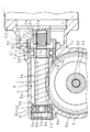
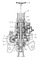
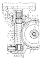
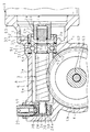
図1は本発明に係る電動式パワーステアリング装置の減速歯車機構部分の構成を示す拡大断面図、図2は電動式パワーステアリング装置の全体構成を示す断面図である。
【0019】
電動式パワーステアリング装置は、操舵補助用のモータ1と、該モータ1の駆動軸1aに雄形継手部2a及び雌形継手部2bを有する軸継手2を介して連結された小歯車としてのウォーム3及び該ウォーム3に噛合する大歯車としてのウォームホイール4を有する減速歯車機構Aと、該減速歯車機構Aを収容して支持する支持部材としてのハウジング5と、減速歯車機構Aに繋がる舵取手段6とを備えている。
【0020】
この舵取手段6は、一端部が舵取りのための操舵輪Bに繋がり、他端部に筒部61aを有する入力軸61と、筒部61a内に挿入されてその一端部が入力軸61の筒部61aに連結され、操舵輪Bに加わる操舵トルクの作用によって捩れるトーションバー62と、他端部がトーションバー62の他端部に連結され、減速歯車機構Aに繋がる出力軸63とを備えており、該出力軸63がユニバーサルジョイントを介して例えばラックピニオン式の舵取機構(不図示)に繋がる。
【0021】
ハウジング5は歯部3aの両端に軸部3b,3cを有するウォーム3を収容し、該ウォーム3の軸部3b,3cを、玉軸受7,8を介して回転自在に支持した第1収容部5aと、ウォームホイール4を収容し、該ウォームホイール4を出力軸63及び該出力軸63に嵌合された2つの玉軸受9,10を介して支持した第2収容部5bとを有する。
【0022】
第1収容部5aはウォーム3の軸長方向に長くなっており、その長手方向一端部には玉軸受7の外輪7aを嵌合支持する支持孔51と、該支持孔51の一端に連なるねじ孔52及びモータ取付部53と、支持孔51の他端に連なり玉軸受7の移動を規制する規制部54とが設けられている。そして、支持孔51に玉軸受7の外輪7aが嵌合され、該外輪7aの一端に当接するねじ環11がねじ孔52に螺着され、外輪7aの他端を前記規制部54に押付けている。また、モータ取付部53にモータ1が取付けられている。
【0023】
第1収容部5aの他端部には玉軸受8の外輪8aを嵌合支持する支持孔55及び該支持孔55の一端に連なり玉軸受8の外輪8aの移動を規制する規制部56が設けられている。支持孔55の他端部は外部に開放されており、開放部に蓋体13が螺着され、外輪8aの他端を前記規制部56に押付けている。
【0024】
減速歯車機構Aのウォーム3は複数条の歯を有する歯部3aの一端に設けられた軸部3bが玉軸受7の内輪7bに軸長方向への移動を可能に挿入され、玉軸受7を介して支持孔51に回転自在に支持されている。歯部3aの他端に設けられた軸部3cは玉軸受8の内輪8bに軸長方向への移動を可能に挿入され、玉軸受8を介して支持孔55に回転自在に支持されている。各内輪7b,8bは歯部3aの両端に当接しており、ウォーム3が軸長方向一方(右方)へ移動する場合は内輪7bを軸長方向一方へ押圧し、ウォーム3が軸長方向他方(左方)へ移動する場合は内輪8bを軸長方向他方へ押圧するようにしてある。
ウォームホイール4は出力軸63の途中に嵌合固定されている。
【0025】
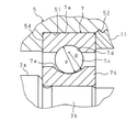
図3は玉軸受の一部を拡大した断面図である。
このようにウォーム3を支持する玉軸受7,8はアキシアル内部隙間の値を日本工業規格の規格値よりも大きくしてある。詳しくは、転動体7c,8cの直径をdとし、内輪7b,8bの軌道溝7d,8dの半径をRとした場合、転動体7c,8cに対する軌道溝7d,8dの曲率d/Rを、日本工業規格で定められた値(53%)よりも大きい値(例えば60〜80%)とすることにより、アキシアル内部隙間の値を日本工業規格の規格値よりも大きくし、玉軸受7,8が支持したウォーム3を外輪7a,8aに対して軸長方向へ移動させることができるようにしてある。尚、転動体7c,8c及び外輪7a,8aの軌道溝7e,8eの半径は規格値にしてある。さらに、アキシアル内部隙間はJISによりラジアル隙間との関係が定義づけられている。
【0026】
モータ1の駆動軸1aとウォーム3の軸部3bとはセレーションを有する雄形継手部2a及び雌形継手部2bを介して軸長方向への相対移動を可能に結合されている。雄形継手部2aは軸部3bの周面にセレーションを設けることにより構成されており、また、雌形継手部2bは駆動軸1aに嵌合固定された筒部材2cの内側にセレーションを設けることにより構成されており、雄形継手部2a及び雌形継手部2bがセレーション嵌合されている。
【0027】
尚、ハウジング5内には、トーションバー62の捩れに応じた入力軸61及び出力軸63の相対回転変位量によって操舵輪Bに加わる操舵トルクを検出するトルクセンサ12が内装されており、該トルクセンサ12が検出したトルク等に基づいてモータ1が駆動制御されるように構成されている。
【0028】
図4はウォームの軸長方向への移動量と軌道溝7d,8dに加わる荷重との関係を示す図である。図4において、移動量及び荷重が正の場合は、ウォーム3に軸長方向一方(右方)の力が加わり、軸長方向一方(右方)へ移動したことを示しており、移動量及び荷重が負の場合は、ウォーム3に軸長方向他方(左方)の力が加わり、軸長方向他方(左方)へ移動したことを示している。
【0029】
以上のように構成された電動式パワーステアリング装置は、一端の軸部3bがモータ1の駆動軸1aに軸継手2を介して結合されたウォーム3の軸部3bを玉軸受7により、また、軸部3cを玉軸受8により夫々回転自在に支持し、ウォーム3を内輪7b,8bに対して軸長方向へ移動可能としてある。また、玉軸受7,8の転動体7c,8cは外輪7a,8a及び内輪7b,8bの軌道溝7d,8d、7e,8eの中央部に位置している。玉軸受7,8はアキシアル内部隙間の値をJIS規格値よりも大きくしてあるため、ウォーム3を外輪7a,8aに対して軸長方向へ移動させることができ、さらに、このウォーム3の軸長方向への移動量を、図4の(a) に示すようにアキシアル内部隙間の値がJIS規格値である従来の玉軸受を用いた場合の移動量(b) に比べて多くすることができる。
【0030】
しかして、モータ1が駆動されない操舵領域、即ち、車両の高速走行時の操舵角が例えば1°程度に小さい操舵領域で操舵されることにより、操舵輪Bの操舵力が入力軸61、トーションバー62、出力軸63及びウォームホイール4を介してウォーム3に伝動されたとき、該ウォーム3に加わる軸長方向への分力によってウォーム3は内輪7bを押圧しつつ外輪7aに対して軸長方向一方(右方)へ移動、又は、内輪8bを押圧しつつ外輪8aに対して軸長方向他方(左方)へ移動し、ウォーム3の回転角が小さくなり、ウォーム3からモータ1の駆動軸1aへの伝動を緩和することができ、モータ1が駆動されない操舵領域での操舵負荷を低減でき、操舵フィーリングを良好にできる。尚、ウォーム3が軸長方向一方(右方)へ移動する場合、軸部3cと内輪8bとは相対移動し、また、ウォーム3が軸長方向他方(左方)へ移動する場合、軸部3bと内輪7bとは相対移動する。
【0031】
しかも、特別の機構を付加することなくウォーム3を支持するための玉軸受7,8を改良した構成であるため、モータ1が駆動されない操舵領域での操舵負荷を低減することができるに拘らず、構造を簡素にでき、ウォーム3部分の小形化を図ることができる。
【0032】
実施の形態2
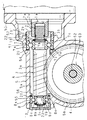
図5は実施の形態2の減速歯車機構部分の構成を示す断面図である。
この実施の形態2の電動式パワーステアリング装置は、実施の形態1の玉軸受7,8の内輪7bと外輪7a、及び内輪8bと外輪8aとの軸長方向への相対移動を抑制する抑制手段としての弾性環14,15を設けたものである。尚、ウォーム3は内輪7b,8bに対して軸長方向へ移動可能になっている。
【0033】
実施の形態2において、軸部3b,3cの途中には止め輪16,17が設けられており、該止め輪16,17と内輪7b,8bとの間に皿ばね、ばね座金、ゴム板等の弾性環14,15が設けられており、該弾性環14,15が内輪7b,8bを外輪7a,8aに対して歯部3a側へ変位させ、内輪7b,8bの外輪7a,8aに対する軸長方向への遊動を防いでいる。
【0034】
実施の形態2にあっては、モータ1が駆動されない操舵領域でウォーム3が軸長方向一方(右方)へ移動する場合、ウォーム3の歯部3aが内輪7bを押圧し、弾性環13を撓ませつつウォーム3が内輪7bとともに右方へ移動し、内輪7bと外輪7aとの軸長方向への相対移動を抑制する。そして、弾性環14の撓み量が増加するに従ってウォーム3の移動量が減少する。また、ウォーム3が軸長方向他方(左方)へ移動する場合、ウォーム3の歯部3aが内輪8bを押圧し、弾性環15を撓ませつつウォーム3が内輪8bとともに左方へ移動し、内輪8bと外輪8aとの軸長方向への相対移動を抑制する。そして、弾性環15の撓み量が増加するに従ってウォーム3の移動量が減少する。尚、ウォーム3が軸長方向一方(右方)へ移動する場合、止め輪17を介して弾性環15が撓むことになるが、内輪8bは移動しない。また、ウォーム3が軸長方向他方(左方)へ移動する場合、止め輪16を介して弾性環14が撓むことになるが、内輪7bは移動しない。
【0035】
また、内輪7b,8b及び外輪7a,8aの軸長方向への相対移動を抑制しているため、ウォーム3及び玉軸受7,8を組み込む場合、内輪7b,8bの外輪7a,8aに対する軸長方向の位置及びウォーム3の玉軸受7,8に対する軸長方向の位置を容易に設定することができ、組込作業性を向上できる。
その他の構成及び作用は実施の形態1と同様であるため、同様の部品については同じ符号を付し、その詳細な説明及び作用効果の説明を省略する。
【0036】
実施の形態3
図6は実施の形態3の減速歯車機構部分の構成を示す断面図である。
この実施の形態3の電動式パワーステアリング装置は、実施の形態1の玉軸受7,8の外輪7a,8aを軸長方向へ移動可能とし、内輪7b,8b及び外輪7a,8aの軸長方向への相対移動を抑制する抑制手段としての弾性環18,19、20,21を設けたものである。尚、ウォーム3は内輪7b,8bに対して軸長方向へ移動可能になっている。
【0037】
実施の形態3において、外輪7a,8aは支持孔51,55に軸長方向への移動を可能に嵌合されており、該外輪7a,8a及び規制部54,56の間に皿ばね、ばね座金、ゴム板等の弾性環20,21が設けられている。軸部3b,3cの途中には止め輪22,23が設けられており、該止め輪22,23と内輪7b,8bとの間に皿ばね、ばね座金、ゴム板等の弾性環18,19が設けられており、該弾性環18,19が内輪7b,8bを外輪7a,8aに対して歯部3a側へ変位させ、内輪7b,8bの外輪7a,8aに対する軸長方向への遊動を防いでいる。
【0038】
実施の形態3にあっては、モータ1が駆動されない操舵領域でウォーム3が軸長方向一方(右方)へ移動する場合、ウォーム3の歯部3aが内輪7bを押圧し、弾性環18を撓ませつつウォーム3が内輪7bとともに右方へ移動し、内輪7bと外輪7aとの軸長方向への相対移動を抑制する。そして、弾性環18の撓み量が増加するに従ってウォーム3の移動量が減少する。また、ウォーム3が軸長方向他方(左方)へ移動する場合、ウォーム3の歯部3aが内輪8bを押圧し、弾性環19を撓ませつつウォーム3が内輪8bとともに左方へ移動し、内輪8b及び外輪8aの軸長方向への相対移動を抑制する。そして、弾性環19の撓み量が増加するに従ってウォーム3の移動量が減少する。尚、ウォーム3が軸長方向一方(右方)へ移動する場合、止め輪23を介して弾性環19が撓み、さらに内輪8b、転動体8c及び外輪8aを介して弾性環21が撓むことになり、玉軸受8の全体が軸長方向一方(右方)へ移動する。また、ウォーム3が軸長方向他方(左方)へ移動する場合、止め輪22を介して弾性環18が撓み、さらに内輪7b、転動体7c及び外輪7aを介して弾性環20が撓むことになり、玉軸受7の全体が軸長方向他方(左方)へ移動する。
また、内輪7b,8b及び外輪7a,8aの軸長方向への相対移動を抑制しているため、ウォーム3及び玉軸受7,8を組み込む場合、内輪7b,8bの外輪7a,8aに対する軸長方向の位置及びウォーム3の玉軸受7,8に対する軸長方向の位置を容易に設定することができ、組込作業性を向上できる。
その他の構成及び作用は実施の形態1、2と同様であるため、同様の部品については同じ符号を付し、その詳細な説明及び作用効果の説明を省略する。
【0039】
実施の形態4
図7は実施の形態4の減速歯車機構部分の構成を示す断面図である。
この実施の形態4の電動式パワーステアリング装置は、反モータ側の玉軸受8に代えて、ウォーム3及びウォームホイール4の回転中心間距離を調整可能として軸部3cを支持する軸受部材24を設け、さらに、モータ側に配置された実施の形態1の玉軸受7の内輪7b及び外輪7aの軸長方向への相対移動を抑制する抑制手段としての弾性環25,26を内輪7bの両端側に設けたものであり、軸部3cは軸受部材24に対して軸長方向へ移動可能としてある。
【0040】
実施の形態4において、ウォーム3は軸受部材24に対して軸長方向へ移動可能としてある。軸部3bの途中には止め輪27が設けられており、該止め輪27と内輪7bとの間、及び歯部3aと内輪7bとの間に夫々皿ばね、ばね座金、ゴム板等の弾性環25,26が設けられており、該弾性環25,26が内輪7bを外輪7aの軸長方向中央に位置させ、内輪7bの外輪7aに対する軸長方向への遊動を防いでいる。
【0041】
第1収容部5aの他端部は支持孔55に代えて、軸部3cが挿入される凹孔57及び該凹孔57の内面に臨み、軸部3cの径方向に向けて穿設、換言すればウォーム3をウォームホイール4に向けて押付ける方向に穿設された円柱形の収容孔58が設けられている。この収容孔58には軸部3cが回転自在に嵌合される軸受部材24と、該軸受部材24を前記押付ける方向へ付勢するコイルバネからなる弾性体28と、収容孔58の外部への開放部を閉じる閉孔部材29とが収容されている。この閉孔部材29は収容孔58の外部への開放側に螺着されている。
【0042】
軸受部材24はその軸長方向の途中、換言すれば収容孔58に沿って移動する移動方向の途中に前記移動方向と直交するように穿設された軸受孔24a及び該軸受孔24aに挿入固定されたすべり軸受30が設けられており、該すべり軸受30を介して軸部3cを軸受部材24に軸長方向へ移動可能に支持してある。
【0043】
実施の形態4にあっては、モータ1が駆動されない操舵領域でウォーム3が軸長方向一方(右方)へ移動する場合、ウォーム3の歯部3aが弾性環26を押圧し、該弾性環26を撓ませつつウォーム3が内輪7bとともに右方へ移動し、内輪7b及び外輪7aの軸長方向への相対移動を抑制する。そして、弾性環26の撓み量が増加するに従ってウォーム3の移動量が減少する。また、ウォーム3が軸長方向他方(左方)へ移動する場合、止め輪27が内輪7bを押圧し、弾性環25を撓ませつつウォーム3が内輪7bとともに左方へ移動し、内輪7b及び外輪7aの軸長方向への相対移動を抑制する。そして、弾性環25の撓み量が増加するに従ってウォーム3の移動量が減少する。
また、内輪7b及び外輪7aの軸長方向への相対移動を抑制しているため、ウォーム3及び玉軸受7を組み込む場合、内輪7bの外輪7aに対する軸長方向の位置及びウォーム3の玉軸受7に対する軸長方向の位置を容易に設定することができ、組込作業性を向上できる。
その他の構成及び作用は実施の形態1、2、3と同様であるため、同様の部品については同じ符号を付し、その詳細な説明及び作用効果の説明を省略する。
【0044】
実施の形態5
図8は実施の形態5の減速歯車機構部分の構成を示す断面図である。
この実施の形態5の電動式パワーステアリング装置は、実施の形態4のようにウォーム3のモータ側を玉軸受7で支持し、反モータ側を軸受部材24で支持した構成において、外輪7aを軸長方向へ移動可能とし、内輪7bとウォーム3との軸長方向への相対移動を阻止し、内輪7bと外輪7aとの軸長方向への相対移動を抑制する抑制手段としての弾性環31,32を外輪7aの両端側に設けたものである。
【0045】
実施の形態5において、転動体7c及び内輪7bの軌道溝7dの半径は規格値とし、外輪7aの軌道溝7eを実施の形態1の内輪7bの軌道溝7dと同様に形成し、玉軸受7のアキシアル内部隙間の値を日本工業規格の規格値よりも大きくし、ウォーム3を外輪7a、ハウジング5に対して軸長方向へ移動させることができるようにしてある。外輪7aは支持孔51に軸長方向への移動を可能に嵌合されており、該外輪7aと規制部54との間、及び外輪7aとねじ環11との間に夫々皿ばね、ばね座金、ゴム板等の弾性環31,32が設けられており、該弾性環31,32が外輪7aを内輪7bの軸長方向中央に位置させ、外輪7aの内輪7bに対する軸長方向への遊動を防いでいる。
軸部3bの途中には内輪7bの軸長方向への移動を規制する止め輪33が設けられている。
【0046】
実施の形態5にあっては、モータ1が駆動されない操舵領域でウォーム3が軸長方向一方(右方)へ移動する場合、ウォーム3の歯部3aが内輪7bを押圧し、該内輪7bがウォーム3とともに移動するとともに、内輪7b及び転動体7cを介して外輪7aを押圧し、弾性環31を撓ませつつウォーム3がさらに右方へ移動し、内輪7bと外輪7aとの軸長方向への相対移動を抑制する。そして、弾性環31の撓み量が増加するに従ってウォーム3の移動量が減少する。また、ウォーム3が軸長方向他方(左方)へ移動する場合、止め輪33が内輪7bを押圧し、該内輪7bがウォーム3とともに移動するとともに、内輪7b及び転動体7cを介して外輪7aを押圧し、弾性環32を撓ませつつウォーム3がさらに左方へ移動し、内輪7b及び外輪7aの軸長方向への相対移動を抑制する。そして、弾性環32の撓み量が増加するに従ってウォーム3の移動量が減少する。
また、内輪7b及び外輪7aの軸長方向への相対移動を抑制しているため、ウォーム3及び玉軸受7を組み込む場合、内輪7bの外輪7aに対する軸長方向の位置及びウォーム3の玉軸受7に対する軸長方向の位置を容易に設定することができ、組込作業性を向上できる。
その他の構成及び作用は実施の形態1、4と同様であるため、同様の部品については同じ符号を付し、その詳細な説明及び作用効果の説明を省略する。
【0047】
尚、以上説明した実施の形態1〜4において、内輪7b,8bの軌道溝7d,8dは円弧面とする他、軌道溝7d,8dの幅方向中央部に直線的な非円弧面を有する構成としてもよい。また、実施の形態5において、外輪7a,8aの軌道溝7e,8eは円弧面とする他、軌道溝7e,8eの幅方向中央部に直線的な非円弧面を有する構成としてもよい。
【0048】
また、玉軸受7,8のアキシアル内部隙間の値を大きくする手段として、実施の形態1〜4にように内輪7b,8b又は内輪7bの軌道溝7d、8dの形状を変えるか、又は、実施の形態5にように外輪7a,8a又は外輪7aの軌道溝7e、8eの形状を変える他、内輪及び外輪の軌道溝の形状を変えてもよい。
【0049】
【発明の効果】
以上詳述したように第1発明によれば、特別の機構を付加することなくモータが駆動されない操舵領域での操舵負荷を低減することができ、操舵フィーリングを良好にできるのであり、しかも、前記操舵負荷を低減することができるに拘らず、構造を簡素にでき、小歯車部分の小形化を図ることができる。
【0050】
第2発明によれば、小歯車及び玉軸受を組み込む場合、内輪の外輪に対する軸長方向の位置及び小歯車の玉軸受に対する軸長方向の位置を容易に設定することができ、組込作業性を向上できる。
【0051】
第3発明によれば、弾性環を小歯車の周りに挿入することにより抑制手段を構成することができるため、組込作業性をより一層向上できる。
【図面の簡単な説明】
【図1】本発明に係る電動式パワーステアリング装置の減速歯車機構部分の構成を示す拡大断面図である。
【図2】本発明に係る電動式パワーステアリング装置の全体構成を示す断面図である。
【図3】本発明に係る電動式パワーステアリング装置の玉軸受の一部を拡大した断面図である。
【図4】ウォームの軸長方向への移動量と軌道溝に加わる荷重との関係を示す図である。
【図5】実施の形態2の減速歯車機構部分の構成を示す断面図である。
【図6】実施の形態3の減速歯車機構部分の構成を示す断面図である。
【図7】実施の形態4の減速歯車機構部分の構成を示す断面図である。
【図8】実施の形態5の減速歯車機構部分の構成を示す断面図である。
【符号の説明】
1 モータ
3 ウォーム(小歯車)
4 ウォームホイール(大歯車)
7,8 玉軸受
7a,8a 外輪
7b,8b 内輪
14,15,18〜21,25,26,31,32 弾性環(抑制手段)[0001]
TECHNICAL FIELD OF THE INVENTION
The present invention relates to an electric power steering device using a motor as a source of a steering assist force.
[0002]
[Prior art]
As an electric power steering device for a vehicle, for example, a steering torque applied to the input shaft is detected by a relative angular displacement of an input shaft connected to a steered wheel and an output shaft coaxially connected to the input shaft via a torsion bar. Driving the steering assist motor based on the detected torque, and transmitting the rotational force of the motor to the steering mechanism via the reduction gear mechanism, thereby controlling the operation of the steering mechanism according to the rotation of the steered wheels. It is configured to assist by the rotation of the motor and to reduce the labor burden on the driver for steering (for example, Patent Document 1).
[0003]
The reduction gear mechanism includes a worm as a small gear coupled to the drive shaft of the motor, and a worm wheel as a large gear meshing with the worm, and the worm wheel is fitted and fixed in the middle of the output shaft. ing.
[0004]
The worm is supported at both ends by a pair of ball bearings to enhance the rotation of the worm.However, since the ball bearing has an axial clearance between the inner ring and the outer ring fitted via a plurality of spheres, The axial clearance is eliminated by applying a preload in the axial direction to the bearing. For example, the outer ring and the inner ring of one ball bearing are relatively moved in the axial direction by rotating a screw ring abutting on one end of the outer ring of one ball bearing that supports one end of the worm, and the other is further connected via the worm. The axial clearance has been eliminated by relatively moving the inner ring and outer ring of the rolling bearing in the axial direction.
[0005]
By the way, the worm of the electric power steering apparatus configured as described above is supported so as not to be able to move in the axial direction with respect to the ball bearings supporting both ends, so that the steering wheel is in a steering neutral state. When the motor is rotated from the initial steering by being steered to the left or right from the position, and the steering assist is performed, when the steering angle is small, for example, about 1 ° when the vehicle is running at high speed, Also, the steering assist is performed, and the steering feeling is degraded. Therefore, in general, the motor is not driven when the steering angle is as small as about 1 °, and the motor is driven when the steering angle exceeds an appropriate steering angle.
[0006]
[Patent Document 1]
Japanese Patent Application Laid-Open No. 2002-21943
[Problems to be solved by the invention]
However, in the case where the motor is not driven until the steering angle exceeds the appropriate steering angle, the steering force of the steered wheels during steering in the steering region where the motor is not driven, that is, in the region near the steering neutral position. Is transmitted to the drive shaft of the motor via the input shaft, torsion bar, output shaft, worm wheel, and worm, and the drive shaft is rotated. As a result, a load for rotating the drive shaft of the motor is applied to the steered wheels via the worm, worm wheel, output shaft, torsion bar, and input shaft, and the steering load increases.
[0008]
By the way, in order to reduce the steering load in the steering region where the motor is not driven, for example, as described in JP-A-11-43062, the worm coupled to the drive shaft of the motor is separated in the axial direction. Two ball bearings movably support the worm in the axial direction, and two disc springs and a spring receiving portion are provided between the inner ring of the two ball bearings and the worm. This is achieved by arranging each inner ring in the axial direction against the outer ring by the elastic restoring force, eliminating the axial clearance of the ball bearing, and suppressing the movement of the worm in both the axial direction. It is possible.
[0009]
With this configuration, when the steering force of the steered wheels is transmitted from the worm wheel to the worm by being steered in the steering region where the motor is not driven, the worm is displaced by the axial force applied to the worm. The spring moves in the axial direction by overcoming the elastic restoring force of the spring, the rotation angle of the worm is reduced, and the transmission from the worm to the drive shaft of the motor is reduced.
[0010]
However, in the case of the structure described in Japanese Patent Application Laid-Open No. 11-43062, two disc springs and two spring receiving portions are required to eliminate the axial clearance of the ball bearing. The worm part becomes large because it becomes complicated and a special mechanism is added.
[0011]
The present invention has been made in view of such circumstances, and supports a small gear rotated by a motor for steering in a steering region in which a steering assist motor is not driven without adding a special mechanism. An object of the present invention is to provide an electric power steering device that can be reduced by a ball bearing.
[0012]
[Means for Solving the Problems]
An electric power steering apparatus according to a first aspect of the present invention includes a small gear rotated by a motor and supported by a ball bearing, and a large gear meshed with the small gear and connected to steering means. In the assisted electric power steering device, the ball bearing is characterized in that the value of the axial internal clearance is larger than the standard value of Japanese Industrial Standard (JIS).
[0013]
In the first invention, since the value of the axial internal clearance of the ball bearing that supports the small gear is larger than the standard value, it is necessary to move the small gear further in the axial direction direction as compared with the JIS standard product. Further, the amount of movement of the small gear in the axial direction can be increased as compared with the case where a ball bearing whose axial internal gap value is a JIS standard value is used. Therefore, the steering load in the steering region where the motor is not driven can be reduced, and the steering feeling can be improved. In addition, since it is configured without adding a special mechanism, it is possible to reduce the steering load in the steering region where the motor is not driven, but to simplify the structure and reduce the size of the small gear portion. Can be planned.
[0014]
An electric power steering apparatus according to a second aspect of the present invention is characterized in that the electric power steering apparatus further includes a suppression unit that suppresses relative movement of the inner race and the outer race of the ball bearing in the axial direction.
[0015]
In the second invention, since the relative movement of the inner ring and the outer ring in the axial direction is suppressed, when the small gear and the ball bearing are incorporated, the position of the inner ring in the axial direction with respect to the outer ring and the ball bearing of the small gear Can be easily set in the axial length direction with respect to, and the assembling workability can be improved.
[0016]
An electric power steering apparatus according to a third aspect is characterized in that the suppression means is an elastic ring.
[0017]
According to the third aspect of the present invention, the suppressing means can be configured by inserting the elastic ring around the small gear, so that the assembling workability can be further improved.
[0018]
BEST MODE FOR CARRYING OUT THE INVENTION
Hereinafter, the present invention will be described in detail with reference to the drawings showing the embodiments.
Embodiment 1
FIG. 1 is an enlarged cross-sectional view showing a configuration of a reduction gear mechanism portion of an electric power steering device according to the present invention, and FIG. 2 is a cross-sectional view showing an entire configuration of the electric power steering device.
[0019]
The electric power steering apparatus comprises a worm as a small gear connected to a steering assist motor 1 and a drive shaft 1a of the motor 1 via a shaft joint 2 having a male joint 2a and a female joint 2b. 3, a reduction gear mechanism A having a worm wheel 4 as a large gear meshing with the worm 3, a housing 5 as a support member for housing and supporting the reduction gear mechanism A, and a steering connected to the reduction gear mechanism A Means 6.
[0020]
One end of the steering means 6 is connected to the steered wheel B for steering, and the other end of the input shaft 61 having a cylindrical portion 61a and the other end of the input shaft 61 which is inserted into the cylindrical portion 61a. A torsion bar 62 connected to the cylindrical portion 61a and twisted by the action of the steering torque applied to the steering wheel B, and an output shaft 63 connected at the other end to the other end of the torsion bar 62 and connected to the reduction gear mechanism A. The output shaft 63 is connected to, for example, a rack and pinion type steering mechanism (not shown) via a universal joint.
[0021]
The housing 5 houses a worm 3 having shaft portions 3b and 3c at both ends of a tooth portion 3a, and a first housing portion rotatably supporting the shaft portions 3b and 3c of the worm 3 via ball bearings 7 and 8. 5a and a second housing portion 5b that houses the worm wheel 4 and supports the worm wheel 4 via an output shaft 63 and two ball bearings 9 and 10 fitted to the output shaft 63.
[0022]
The first housing portion 5a is elongated in the axial direction of the worm 3. A support hole 51 for fitting and supporting the outer ring 7a of the ball bearing 7 at one longitudinal end thereof, and a screw connected to one end of the support hole 51 are provided. A hole 52 and a motor mounting portion 53 are provided, and a restricting portion 54 which is connected to the other end of the support hole 51 and restricts the movement of the ball bearing 7 is provided. The outer ring 7a of the ball bearing 7 is fitted into the support hole 51, the screw ring 11 abutting on one end of the outer ring 7a is screwed into the screw hole 52, and the other end of the outer ring 7a is pressed against the regulating portion 54. I have. Further, the motor 1 is mounted on the motor mounting portion 53.
[0023]
A support hole 55 for fitting and supporting the outer ring 8a of the ball bearing 8 and a restricting portion 56 connected to one end of the support hole 55 for restricting the movement of the outer ring 8a of the ball bearing 8 are provided at the other end of the first housing portion 5a. Have been. The other end of the support hole 55 is open to the outside, and the lid 13 is screwed to the open portion to press the other end of the outer ring 8 a against the restricting portion 56.
[0024]
In the worm 3 of the reduction gear mechanism A, a shaft portion 3b provided at one end of a tooth portion 3a having a plurality of teeth is inserted into an inner ring 7b of a ball bearing 7 so as to be able to move in the axial direction. It is rotatably supported by the support hole 51 through the. The shaft portion 3c provided at the other end of the tooth portion 3a is inserted into the inner ring 8b of the ball bearing 8 so as to be movable in the axial direction, and is rotatably supported by the support hole 55 via the ball bearing 8. . Each of the inner rings 7b and 8b is in contact with both ends of the tooth portion 3a. When the worm 3 moves in one axial direction (to the right), the inner ring 7b is pressed in one axial direction, and the worm 3 is moved in the axial direction. When moving to the other side (left side), the inner ring 8b is pressed in the other axial direction.
The worm wheel 4 is fitted and fixed in the middle of the output shaft 63.
[0025]
FIG. 3 is an enlarged sectional view of a part of the ball bearing.
As described above, the ball bearings 7 and 8 supporting the worm 3 have a larger value of the axial internal clearance than the standard value of Japanese Industrial Standard. Specifically, when the diameter of the rolling elements 7c and 8c is d and the radius of the raceway grooves 7d and 8d of the inner races 7b and 8b is R, the curvature d / R of the raceway grooves 7d and 8d with respect to the rolling elements 7c and 8c is: By setting a value (for example, 60 to 80%) larger than the value (53%) specified by the Japanese Industrial Standard, the value of the axial internal gap is made larger than the standard value of the Japanese Industrial Standard, and the ball bearings 7, 8 Can be moved in the axial direction with respect to the outer rings 7a and 8a. The radius of the raceway grooves 7e, 8e of the rolling elements 7c, 8c and the outer rings 7a, 8a is set to a standard value. Further, the relationship between the axial internal gap and the radial gap is defined by JIS.
[0026]
The drive shaft 1a of the motor 1 and the shaft 3b of the worm 3 are connected via a male joint 2a and a female joint 2b having serrations so as to be relatively movable in the axial direction. The male joint portion 2a is formed by providing serrations on the peripheral surface of the shaft portion 3b, and the female joint portion 2b is provided with serrations inside a cylindrical member 2c fitted and fixed to the drive shaft 1a. The male joint 2a and the female joint 2b are serrated.
[0027]
The housing 5 includes a torque sensor 12 that detects a steering torque applied to the steered wheels B based on a relative rotational displacement of the input shaft 61 and the output shaft 63 in accordance with the torsion of the torsion bar 62. The drive of the motor 1 is controlled based on the torque and the like detected by the sensor 12.
[0028]
FIG. 4 is a diagram showing the relationship between the amount of movement of the worm in the axial direction and the load applied to the track grooves 7d and 8d. In FIG. 4, when the movement amount and the load are positive, it indicates that a force in one axial direction (rightward) is applied to the worm 3 and the worm 3 moves in one axial direction (rightward). When the load is negative, it indicates that the worm 3 is applied with a force in the other axial direction (left) and moved in the other axial direction (left).
[0029]
In the electric power steering apparatus configured as described above, the shaft portion 3b of the worm 3 in which the shaft portion 3b at one end is coupled to the drive shaft 1a of the motor 1 via the shaft coupling 2 by the ball bearing 7, and The shaft portion 3c is rotatably supported by a ball bearing 8, and the worm 3 is movable in the axial direction with respect to the inner rings 7b, 8b. The rolling elements 7c, 8c of the ball bearings 7, 8 are located at the center of the raceway grooves 7d, 8d, 7e, 8e of the outer rings 7a, 8a and the inner rings 7b, 8b. Since the ball bearings 7 and 8 have a larger axial internal clearance value than the JIS standard value, the worm 3 can be moved in the axial direction with respect to the outer rings 7a and 8a. As shown in FIG. 4 (a), the amount of movement in the longitudinal direction can be made larger than the amount of movement (b) when a conventional ball bearing whose axial internal gap value is a JIS standard value is used. it can.
[0030]
Thus, by steering in a steering region where the motor 1 is not driven, that is, in a steering region where the steering angle during high-speed running of the vehicle is small, for example, about 1 °, the steering force of the steered wheels B is reduced by the input shaft 61 and the torsion bar. When the worm 3 is transmitted to the worm 3 via the output shaft 63 and the worm wheel 4, the worm 3 is pressed against the inner ring 7 b by the component force in the axial direction applied to the worm 3 while being pressed against the outer ring 7 a in the axial direction. The worm 3 moves to one side (to the right) or moves to the other side (to the left) in the axial direction with respect to the outer ring 8a while pressing the inner ring 8b. The transmission to 1a can be reduced, the steering load in the steering region where the motor 1 is not driven can be reduced, and the steering feeling can be improved. When the worm 3 moves in one axial direction (to the right), the shaft 3c and the inner ring 8b move relative to each other. When the worm 3 moves in the other axial direction (to the left), the shaft 3 3b and the inner ring 7b move relatively.
[0031]
In addition, since the ball bearings 7, 8 for supporting the worm 3 are improved without adding a special mechanism, the steering load in the steering region where the motor 1 is not driven can be reduced. The structure can be simplified, and the worm 3 can be reduced in size.
[0032]
Embodiment 2
FIG. 5 is a sectional view showing a configuration of a reduction gear mechanism portion according to the second embodiment.
The electric power steering apparatus according to the second embodiment is a suppression means for suppressing relative movement of the inner ring 7b and the outer ring 7a and the inner ring 8b and the outer ring 8a of the ball bearings 7 and 8 of the first embodiment in the axial direction. The elastic rings 14 and 15 are provided. The worm 3 is movable in the axial direction with respect to the inner rings 7b, 8b.
[0033]
In the second embodiment, retaining rings 16, 17 are provided in the middle of the shaft portions 3b, 3c, and disc springs, spring washers, rubber plates, etc. are provided between the retaining rings 16, 17 and the inner rings 7b, 8b. The elastic rings 14 and 15 displace the inner rings 7b and 8b toward the teeth 3a with respect to the outer rings 7a and 8a, and the shafts of the inner rings 7b and 8b with respect to the outer rings 7a and 8a. Prevents movement in the long direction.
[0034]
In the second embodiment, when the worm 3 moves in one axial direction (to the right) in the steering region where the motor 1 is not driven, the teeth 3a of the worm 3 press the inner ring 7b and the elastic ring 13 is moved. The worm 3 moves to the right together with the inner ring 7b while bending, thereby suppressing the relative movement of the inner ring 7b and the outer ring 7a in the axial direction. Then, as the amount of deflection of the elastic ring 14 increases, the amount of movement of the worm 3 decreases. When the worm 3 moves in the other axial direction (to the left), the teeth 3a of the worm 3 press the inner ring 8b, and the worm 3 moves to the left together with the inner ring 8b while bending the elastic ring 15, The relative movement of the inner ring 8b and the outer ring 8a in the axial direction is suppressed. Then, as the amount of deflection of the elastic ring 15 increases, the amount of movement of the worm 3 decreases. When the worm 3 moves in one axial direction (rightward), the elastic ring 15 bends via the retaining ring 17, but the inner ring 8b does not move. When the worm 3 moves in the other axial direction (to the left), the elastic ring 14 bends via the retaining ring 16, but the inner ring 7b does not move.
[0035]
Further, since the relative movement of the inner rings 7b, 8b and the outer rings 7a, 8a in the axial direction is suppressed, when the worm 3 and the ball bearings 7, 8 are incorporated, the axial length of the inner rings 7b, 8b with respect to the outer rings 7a, 8a. The position of the worm 3 and the position of the worm 3 in the axial direction with respect to the ball bearings 7 and 8 can be easily set, and the assembling workability can be improved.
Since other configurations and operations are the same as those of the first embodiment, the same reference numerals are given to the same components, and the detailed description and the description of the operation and effects are omitted.
[0036]
Embodiment 3
FIG. 6 is a sectional view showing a configuration of a reduction gear mechanism portion according to the third embodiment.
The electric power steering apparatus according to the third embodiment enables the outer rings 7a, 8a of the ball bearings 7, 8 according to the first embodiment to move in the axial direction, and the axial directions of the inner rings 7b, 8b and the outer rings 7a, 8a. The elastic rings 18, 19, 20, and 21 are provided as suppression means for suppressing relative movement of the elastic members. The worm 3 is movable in the axial direction with respect to the inner rings 7b, 8b.
[0037]
In the third embodiment, the outer races 7a and 8a are fitted into the support holes 51 and 55 so as to be movable in the axial direction, and a disc spring and a spring are provided between the outer races 7a and 8a and the regulating portions 54 and 56. Elastic rings 20, 21 such as washers and rubber plates are provided. Retaining rings 22, 23 are provided in the middle of the shaft portions 3b, 3c, and elastic rings 18, 19, such as disc springs, spring washers, and rubber plates, are provided between the retaining rings 22, 23 and the inner rings 7b, 8b. The elastic rings 18 and 19 displace the inner rings 7b and 8b toward the teeth 3a with respect to the outer rings 7a and 8a, and allow the inner rings 7b and 8b to move in the axial direction with respect to the outer rings 7a and 8a. I'm preventing.
[0038]
In the third embodiment, when the worm 3 moves in one axial direction (to the right) in the steering region where the motor 1 is not driven, the teeth 3a of the worm 3 press the inner ring 7b and the elastic ring 18 is moved. The worm 3 moves to the right together with the inner ring 7b while bending, thereby suppressing the relative movement of the inner ring 7b and the outer ring 7a in the axial direction. Then, as the amount of deflection of the elastic ring 18 increases, the amount of movement of the worm 3 decreases. When the worm 3 moves in the other axial direction (to the left), the teeth 3a of the worm 3 press the inner ring 8b, and the worm 3 moves to the left together with the inner ring 8b while bending the elastic ring 19, The relative movement of the inner ring 8b and the outer ring 8a in the axial direction is suppressed. Then, as the amount of deflection of the elastic ring 19 increases, the amount of movement of the worm 3 decreases. When the worm 3 moves in one direction (rightward) in the axial direction, the elastic ring 19 is bent via the retaining ring 23, and the elastic ring 21 is further bent via the inner ring 8b, the rolling element 8c and the outer ring 8a. , And the entire ball bearing 8 moves in one axial direction (rightward). When the worm 3 moves in the other axial direction (to the left), the elastic ring 18 bends via the retaining ring 22 and further the elastic ring 20 bends via the inner ring 7b, the rolling element 7c and the outer ring 7a. , And the entire ball bearing 7 moves in the other axial direction (to the left).
Further, since the relative movement of the inner rings 7b, 8b and the outer rings 7a, 8a in the axial direction is suppressed, when the worm 3 and the ball bearings 7, 8 are incorporated, the axial length of the inner rings 7b, 8b with respect to the outer rings 7a, 8a. The position of the worm 3 and the position of the worm 3 in the axial direction with respect to the ball bearings 7 and 8 can be easily set, and the assembling workability can be improved.
Other configurations and operations are the same as those of the first and second embodiments. Therefore, the same reference numerals are given to the same components, and the detailed description and the description of the effects are omitted.
[0039]
Embodiment 4
FIG. 7 is a cross-sectional view showing a configuration of a reduction gear mechanism portion according to the fourth embodiment.
The electric power steering apparatus according to the fourth embodiment includes a bearing member 24 that supports the shaft portion 3c so that the distance between the rotation centers of the worm 3 and the worm wheel 4 can be adjusted, instead of the ball bearing 8 on the side opposite to the motor. Further, elastic rings 25 and 26 as restraining means for suppressing relative movement of the inner ring 7b and the outer ring 7a of the ball bearing 7 of the first embodiment arranged in the motor side in the axial direction are provided on both ends of the inner ring 7b. The shaft portion 3c is movable in the axial direction with respect to the bearing member 24.
[0040]
In the fourth embodiment, the worm 3 is movable with respect to the bearing member 24 in the axial direction. A retaining ring 27 is provided in the middle of the shaft portion 3b. The elasticity of a disc spring, a spring washer, a rubber plate, or the like is provided between the retaining ring 27 and the inner ring 7b and between the tooth portion 3a and the inner ring 7b. Rings 25 and 26 are provided, and the elastic rings 25 and 26 position the inner ring 7b at the center of the outer ring 7a in the axial direction, thereby preventing the inner ring 7b from moving in the axial direction with respect to the outer ring 7a.
[0041]
The other end of the first housing portion 5a faces the concave hole 57 into which the shaft portion 3c is inserted and the inner surface of the concave hole 57 instead of the support hole 55, and is bored in the radial direction of the shaft portion 3c. In this case, a cylindrical accommodation hole 58 formed in a direction in which the worm 3 is pressed toward the worm wheel 4 is provided. A bearing member 24 into which the shaft portion 3 c is rotatably fitted, an elastic body 28 made of a coil spring for urging the bearing member 24 in the pressing direction, A closing member 29 for closing the opening is accommodated. The closing member 29 is screwed on the opening side of the housing hole 58 to the outside.
[0042]
The bearing member 24 is provided with a bearing hole 24a formed in the axial direction thereof, in other words, in a moving direction of moving along the housing hole 58 so as to be orthogonal to the moving direction, and inserted and fixed in the bearing hole 24a. A slide bearing 30 is provided, and the shaft portion 3c is supported by the bearing member 24 via the slide bearing 30 so as to be movable in the axial direction.
[0043]
In the fourth embodiment, when the worm 3 moves in one axial direction (to the right) in the steering region where the motor 1 is not driven, the teeth 3a of the worm 3 press the elastic ring 26, The worm 3 moves to the right together with the inner ring 7b while bending 26, thereby suppressing the relative movement of the inner ring 7b and the outer ring 7a in the axial direction. Then, as the amount of deflection of the elastic ring 26 increases, the amount of movement of the worm 3 decreases. When the worm 3 moves in the other axial direction (to the left), the retaining ring 27 presses the inner ring 7b, and the worm 3 moves to the left together with the inner ring 7b while bending the elastic ring 25. The relative movement of the outer ring 7a in the axial direction is suppressed. Then, as the amount of deflection of the elastic ring 25 increases, the amount of movement of the worm 3 decreases.
Further, since the relative movement of the inner ring 7b and the outer ring 7a in the axial direction is suppressed, when the worm 3 and the ball bearing 7 are incorporated, the position of the inner ring 7b in the axial direction with respect to the outer ring 7a and the ball bearing 7 of the worm 3 Can be easily set in the axial length direction with respect to, and the assembling workability can be improved.
Other configurations and operations are the same as those of the first, second, and third embodiments. Therefore, the same components are denoted by the same reference numerals, and the detailed description and the description of the operation and effects are omitted.
[0044]
Embodiment 5
FIG. 8 is a sectional view showing a configuration of a reduction gear mechanism portion according to the fifth embodiment.
The electric power steering apparatus according to the fifth embodiment has a configuration in which the motor side of the worm 3 is supported by the ball bearing 7 and the opposite side to the motor is supported by the bearing member 24 as in the fourth embodiment, and The elastic ring 31 as a restraining means that can move in the longitudinal direction, prevents relative movement of the inner ring 7b and the worm 3 in the axial direction, and suppresses relative movement of the inner ring 7b and the outer ring 7a in the axial direction. 32 are provided at both ends of the outer ring 7a.
[0045]
In the fifth embodiment, the radius of the raceway groove 7d of the rolling element 7c and the inner ring 7b is a standard value, and the raceway groove 7e of the outer ring 7a is formed in the same manner as the raceway groove 7d of the inner ring 7b of the first embodiment. The value of the axial internal clearance is made larger than the standard value of the Japanese Industrial Standard so that the worm 3 can be moved in the axial direction with respect to the outer ring 7a and the housing 5. The outer ring 7a is fitted in the support hole 51 so as to be movable in the axial direction, and a disc spring and a spring washer are provided between the outer ring 7a and the restricting portion 54 and between the outer ring 7a and the screw ring 11, respectively. And elastic rings 31 and 32 such as rubber plates. The elastic rings 31 and 32 position the outer ring 7a at the center of the inner ring 7b in the axial length direction, and allow the outer ring 7a to move in the axial direction with respect to the inner ring 7b. I'm preventing.
In the middle of the shaft portion 3b, there is provided a retaining ring 33 for restricting the movement of the inner ring 7b in the axial direction.
[0046]
In the fifth embodiment, when the worm 3 moves in one axial direction (to the right) in the steering region where the motor 1 is not driven, the teeth 3a of the worm 3 press the inner ring 7b, and the inner ring 7b The worm 3 moves together with the worm 3 and presses the outer ring 7a via the inner ring 7b and the rolling elements 7c to move the worm 3 further rightward while bending the elastic ring 31 in the axial direction of the inner ring 7b and the outer ring 7a. The relative movement of. Then, as the amount of deflection of the elastic ring 31 increases, the amount of movement of the worm 3 decreases. When the worm 3 moves in the other axial direction (to the left), the retaining ring 33 presses the inner ring 7b, the inner ring 7b moves together with the worm 3, and the outer ring 7a moves through the inner ring 7b and the rolling elements 7c. , The worm 3 moves further leftward while bending the elastic ring 32, thereby suppressing the relative movement of the inner ring 7b and the outer ring 7a in the axial direction. Then, as the amount of deflection of the elastic ring 32 increases, the amount of movement of the worm 3 decreases.
Further, since the relative movement of the inner ring 7b and the outer ring 7a in the axial direction is suppressed, when the worm 3 and the ball bearing 7 are incorporated, the position of the inner ring 7b in the axial direction with respect to the outer ring 7a and the ball bearing 7 of the worm 3 Can be easily set in the axial length direction with respect to, and the assembling workability can be improved.
Since other configurations and operations are the same as those of the first and fourth embodiments, the same components are denoted by the same reference numerals, and the detailed description and the description of the operation and effects will be omitted.
[0047]
In the first to fourth embodiments described above, the raceway grooves 7d and 8d of the inner races 7b and 8b have arcuate surfaces, and have a linear non-arc surface at the center in the width direction of the raceway grooves 7d and 8d. It may be. Further, in the fifth embodiment, the raceway grooves 7e, 8e of the outer races 7a, 8a may have a circular arc surface, and may have a linear non-circular surface at the center in the width direction of the raceway grooves 7e, 8e.
[0048]
As means for increasing the value of the axial internal clearance of the ball bearings 7, 8, the shape of the inner races 7b, 8b or the raceway grooves 7d, 8d of the inner race 7b is changed as in Embodiments 1 to 4, or As in the fifth embodiment, in addition to changing the shape of the raceway grooves 7e, 8e of the outer ring 7a, 8a or the outer ring 7a, the shape of the raceway grooves of the inner ring and the outer ring may be changed.
[0049]
【The invention's effect】
As described in detail above, according to the first aspect, the steering load in the steering region where the motor is not driven can be reduced without adding a special mechanism, and the steering feeling can be improved. Although the steering load can be reduced, the structure can be simplified and the small gear portion can be downsized.
[0050]
According to the second aspect of the invention, when the small gear and the ball bearing are incorporated, the position of the inner ring in the axial direction with respect to the outer ring and the position of the small gear in the axial direction with respect to the ball bearing can be easily set. Can be improved.
[0051]
According to the third aspect, the suppressing means can be configured by inserting the elastic ring around the small gear, so that the assembling workability can be further improved.
[Brief description of the drawings]
FIG. 1 is an enlarged sectional view showing a configuration of a reduction gear mechanism portion of an electric power steering device according to the present invention.
FIG. 2 is a cross-sectional view showing the overall configuration of the electric power steering device according to the present invention.
FIG. 3 is an enlarged sectional view of a part of a ball bearing of the electric power steering device according to the present invention.
FIG. 4 is a diagram illustrating a relationship between an amount of movement of a worm in an axial length direction and a load applied to a track groove.
FIG. 5 is a cross-sectional view illustrating a configuration of a reduction gear mechanism portion according to a second embodiment.
FIG. 6 is a cross-sectional view illustrating a configuration of a reduction gear mechanism portion according to a third embodiment.
FIG. 7 is a cross-sectional view illustrating a configuration of a reduction gear mechanism portion according to a fourth embodiment.
FIG. 8 is a cross-sectional view illustrating a configuration of a reduction gear mechanism portion according to a fifth embodiment.
[Explanation of symbols]
1 motor 3 worm (small gear)
4 Worm wheel (large gear)
7, 8 ball bearings 7a, 8a outer rings 7b, 8b inner rings 14, 15, 18 to 21, 25, 26, 31, 32 elastic ring (suppression means)