【0001】
【発明の属する技術分野】
本発明は、床下などの狭い場所や劣悪な路面環境を走行しながら作業を行うロボットに適用される走行装置に関する。
【0002】
【従来の技術】
近年、産業ロボットが人に代わって作業を代行する分野が拡大している。例えば、入り込んでの作業が容易でない狭い場所や、劣悪な作業環境でロボットが活用されつつある。その具体例として、木造家屋の床下での蟻などの害虫駆除を目的した薬剤散布作業をするロボットや、家屋の耐久性を診断するロボットがある。
【0003】
古くなった木造家屋での薬剤散布や耐久性を診断する場合、従来は、作業員が床下にもぐり込んで散布作業を行ったり、診断士が柱や床、筋交いの腐朽状態を直接目視にて確認する方法が専ら行われている。しかしながら、床下の状況は、それこそ家屋によって様々に異なり、人が通り抜けできない狭い床下や、粉塵や害虫の死骸が溜まっていたりというように、とても人が入り込めないようになっていることがある。そのような劣悪な状況では、労働衛生上の問題があるばかりでなく、薬剤が散布されない場所が残ったり、柱や床などの状態を離れた位置から点検することになって正確な診断が難しくなる。
【0004】
そこで、近年は、薬剤散布作業等を代行させるロボットが開発されている(例えば、特許文献1参照)。
【0005】
【特許文献1】
特許第2594880号公報
床下のような不整地でロボットが円滑に走行できるように、無限軌道方式が一般に採用されている。キャタピラを使った走行装置は、不整地での安定した走行を可能とする。
【0006】
【発明が解決しようとする課題】
しかしながら、無限軌道方式の走行装置では、装置自体が大型化し重量が増大し、大きな駆動トルクを要するため、必然的にモータは大型化し、バッテリーの消耗が大きく走行継続時間が短くなり、また、高価となるという重大な欠点がある。
【0007】
他方、床下に進入させて薬剤散布や柱、床などの撮影を目的するロボットの場合、可及的に小型化する必要がある。消費電力を小さくて走行装置を小型化するためには、4輪駆動方式が適しているが、床下には配管などの障害物があることが多く、前輪が障害物を乗り越えたとしても障害物が走行装置本体の底面に当たり前輪または後輪が浮き上がってしまい、不安定な状態で接地している他方の前輪または後輪がスリップしてしまう結果、移動不能になるという問題がある。
【0008】
そこで、本発明の目的は、前記従来技術の有する問題点を解消し、無限軌道方式によらず、4輪駆動方式でありながら円滑に障害物に乗り越えて自在に動き回ることができ、しかも、可及的に小型化、低価格を達成できるようにしたロボットの走行装置を提供することにある。
【0009】
【課題を解決するための手段】
前記の目的を達成するために、本発明は、所定の作業を行う作業装置を搭載する車体と、該車体に設けられた前輪および後輪と、該前輪および後輪を駆動する4輪駆動機構を有する遠隔操縦式のロボットの走行装置において、前輪および後輪のそれぞれの車輪にタイミングプーリーを同軸に設け、前記4輪駆動機構の駆動モータのトルクをそれぞれ前記タイミングプーリーに巻き掛けたタイミングベルトで同期して伝達し、前記タイミングベルトの下側のベルトを車輪接地面と前記車体の底面の間に定位して走行させるようにしたことを特徴とするものである。
【0010】
前記の本発明の構成において、前記タイミングプーリーは、前記車輪のタイヤホイールの本体部を構成することが好ましく、また、前記タイミングベルトは、両面に凹凸のあるベルトからなることが好ましい。
【0011】
【発明の実施の形態】
以下、本発明によるロボットの走行装置の一実施形態について、添付の図面を参照しながら説明する。
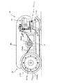
図1は、本発明による走行装置を自走撮影ロボットに適用に適用した実施形態を示す図である。図1において、参照符号10は自走撮影ロボットの全体を示す。この実施形態による自走撮影ロボットは、木造家屋の床下を走行させて、柱や床などの腐朽状態を診断するために写真撮影を行うロボットである。
【0012】
参照符号12は走行装置の車体を示し、14は車体12の上を覆うカバー、11a、11bは後輪、13a、13bは前輪を示している。参照符号20はデジタルカメラを示し、このデジタルカメラ20は、図1に示されるように、車体前方の低位置に配置されている。
【0013】
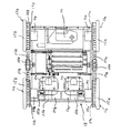
図2は、カバー14を取り外した状態で示した自走撮影ロボット10の平面図である。
この車体12の後方には、4輪駆動方式の駆動装置18が配置されている。21a、21bは電源であるDCバッテリーを示す。それぞれDCバッテリー21a、21bは車体後方で左右に配置されたブラシレスDCモータを用いた車輪駆動モータ22a、22bと接続されている。それぞれ車輪駆動モータ22a、22bには、減速機23a、23bが一体的に連結されており、軸受24a、24bによって支持された後輪軸25a、25bはそれぞれ減速機23a、23bに連結されている。図3に示すように、前輪13a、13bの車軸15a、15bは軸受16a、16bによって支承されている。
【0014】
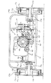
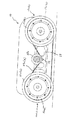
この実施形態の走行装置では、図3に示すように前輪13a、13bに、タイヤ15a、15bが取り付けられるようになっており、タイヤホイールの本体部をタイミングプーリ17a、17bが兼用する構造となっている。タイミングプーリ17a、17bの側面にはタイヤ装着用のリング19a、19bが一体的に締結されている。同様に、各後輪11a、11bでは、タイヤホイールの本体部をタイミングプーリー26a、26bが兼用する構造となっており、タイヤ装着用のリング19a、19bを介してタイヤ15a、15bが装着されている。図4に示されるように、前輪後輪の右側のタイミングプーリー17a、26aにはタイミングベルト27aが巻き掛けられており、右側の車輪駆動モータ22aの駆動トルクは、後輪11aに直接伝達されるとともに前輪13aにもタイミングベルト27aを介して伝達されるようになっている。同様に、左側の前後車輪のタイミングプーリー17b、26bにもタイミングベルト27bが巻き掛けられ、左側の車輪駆動モータ22bの駆動トルクは、後輪11bに直接伝達されるとともに前輪13bにもタイミングベルト27bを介して伝達される。このように、前輪後輪のタイヤホイールの本体部を兼用するタイミングプーリ17a、17b、26a、26bにタイミングベルト27a、27bを巻き掛けることにより、タイミングベルト27a、27bの下側のベルトは、前後輪の接地面と車体12の底面の間に定位して走行することができる。
【0015】
このような4輪駆動方式の駆動装置18では、車輪駆動モータ22a、22bの駆動トルクを左右それぞれ独立に左右の前後輪にベルト伝動として伝達し、左右の車輪駆動モータ22a、22bを異なる回転方向に回転させることにより、ステアリング機能を持たせるとともに車体12全体を左右に旋回させることが可能となっている。
【0016】
また、車体12の左右中央には、テンションアイドラ28a、28bが配置されており、このテンションアイドラ28a、28bは、上側を走行するタイミングベルト27a、27bを下向きに押し付け、タイミングベルト27a、27bに緩みが生じるのを防止している。なお、このテンションアイドラ28a、28bは、車体12にある上下に長さをもち長穴29(図4参照)を介して取り付けられ、上下の位置を調整できるようになっている。
【0017】
次に、以上のような走行装置に搭載されるデジタルカメラ20について説明する。
【0018】
図3にデジタルカメラ20の正面を示す。この図3において、デジタルカメラ20は、傾動可能な傾動台30に固定されている。傾動台30の左右両側には、支持フレーム31a、31bが垂直に立ち上がるようになっていて、傾動台30の左右両側に設けられた支軸32a、32bは、支持フレーム31a、31bに取り付けられた軸受33a、33bによって支承されている。
【0019】
図3において、デジタルカメラ20の向かって右側には、デジタルカメラ20の傾動動作を駆動するチルト用DCモータ34が配置されている。このチルト用DCモータ34は、減速機35とブレーキ機能が一体的にユニット化されたモータである。減速機35の出力軸には、駆動側の小歯車36が軸着されている。他方、傾動台30を支える支軸32bには、小歯車36に噛み合っている従動側の大歯車37が軸着されている。また、支軸32bには、傾動位置検出ディスク38が取り付けられ、センサー39によって傾動位置の検出を行っている。
【0020】
このような傾動機構により、傾動台30は図3に示す水平な姿勢を中立位置として鉛直面内を上方に90度、下方90度、合計180度傾動することができる。これにより、デジタルカメラ20は、レンズの光軸を真下の指向させることもできるし、真上に対して指向させることもできる。なお、レンズの光軸を左右に動かす場合には、上述したように、4輪駆動機構18の左右の車輪駆動モータ22a、22bを異なる回転方向に回転させることにより、車体全体を左右に360度旋回させることができるため、デジタルカメラ20の光軸は全方位を指向させることが可能となっている。
本実施形態でロボットに搭載されるデジタルカメラ20は、常時オートフォーカの設定ができ、ズーム機能を持ち、本体にビデオ出力部、記憶装置を内蔵する、市場で市販されている携帯型のデジタルカメラである。撮像素子の画素数としては、高画質静止画像を撮影するために、300万画素以上であることが好ましい。
【0021】
このようなデジタルカメラ20が取り付けられている傾動台30については、車体12との間は、装置、器具類を何も配置せずに傾動を許容する限度で空間としと、デジタルカメラ20が可及的に低位置に配置されるようになっている。デジタルカメラ20が地面を向いた場合に地面を撮影できるように、車体12には窓40が開口するようになつている。
【0022】
傾動台30においてデジタルカメラ20の回りには、デジタルカメラ20による近接撮影動作を実現するために必要に操作するカメラ操作部の構成要素が配置されている。
【0023】
図3において、デジタルカメラ20のレンズ40の周囲には、主として近接撮影照明用の高輝度LEDランプ42が同心円状に離散的に配置されている。また、レンズ40の左右下側には、一対の前照灯43、43が配置されている。この前照灯43、43は、この実施形態では、それぞれが3個の高輝度LEDランプを組み合わせて構成されている。
【0024】
傾動台30の下側に取り付けられているのは、ソレノイド44、45である。ソレノイド44、45は、図1に示すように、内蔵するスピンドルが突出するとレバー46を動かしてそれぞれデジタルカメラ20の背面に設けられている操作釦47を押すようになっている。これら操作釦については後述する。
【0025】
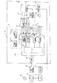
次に、図5は、自走撮影ロボットおよびそれを利用する床下診断システムのブロック構成図である。
図5において、参照符号50は、自走撮影ロボットの制御部を示し、52は、デジタルカメラ20のカメラ操作部を示す。53は、自走撮影ロボットを遠隔する遠隔操作装置を示す。この遠隔操作装置53は、送信機を有し、ロボット側に設けられている受信機54に操作信号をワイヤレスで送信する。受信機54に送られた操作信号は、シーケンサ55として用いられる制御部50のプログラマブルコントローラに導入される。参照符号56は、チルト用DCモータ34を駆動するチルトモータ駆動回路を示し、57は、近接撮影照明用の高輝度LEDランプ42と前照灯43を駆動するランプ駆動回路を示し、58は、デジタルカメラ20のシャッターを切ったり、ズームを調整する作動信号を発生するカメラ操作信号発生回路を示す。60は、走行装置を駆動する4輪駆動装置18の車輪駆動モータ24a、24bの停止、正逆転、回転速度の差動制御を行う車輪モータ制御回路を示す。走行装置を遠隔操縦するための操作信号や、デジタルカメラ20で近接撮影をするための各種操作信号は、シーケンサ55に受信機54から与えられ、シーケンサ55はこれらの信号に基づいて、上記の各回路に指令信号を与えて、走行装置の走行させ、デジタルカメラ20を実際に作動させるための所定のシーケンスを制御する。
【0026】
カメラ操作部52は、デジタルカメラ20を上下に傾動させるチルト用DCモータ34、近接撮影照明用の高輝度LEDランプ42、前照灯43の他、デジタルカメラ20のシャッターを作動し、またズーミング作動させるシャッターコントローラ62、第1のモード切替スイッチ63をオンオフする前述した第1のソレノイド45、第2のモード切替スイッチ64をオンオフする第2のソレノイド46を備えている。シャッターコントローラ62は、カメラ操作信号発生回路58に接続されている。第1ソレノイド45は、シーケンサ55から与えられる信号によって励磁されたときに第1モード切替スイッチ63をONにし、デジタルカメラ20のモードを撮影した写真を確認再生するモードに替えるようになっている。同様に、第2ソレノイド46は、シーケンサ55によって励磁されると第2モード切替スイッチ64をONに入れ、このモードでは、シャッターを切ったときに同時にフラッシュが自動発光するモードが解除されるようになっている。
【0027】
デジタルカメラ20は、カメラ本体65の他、画像記憶装置66およびビデオ出力部67を備えている。ビデオ出力部67には、ロボットに搭載されている映像送信機68が接続されている。この映像送信機68は、外部に設置されている映像受信機69にデジタル伝送方式によって映像信号を送信する。映像受信機69には、モニタ装置70が接続され、伝送されてきた映像信号をこのモニタ装置70に表示することができるようになっている。
【0028】
なお、図5において、参照符号80は、パーソナルコンピュータを利用した静止画像再生装置を示している。この静止画像再生装置80では、デジタルカメラ20で撮影して画像記憶装置66に記録された画像データを画像ファイル82として取り込み、この画像ファイル82を再生するために必要な画像再生ソフトウェアがインストールされている。
【0029】
本実施形態は、以上のように構成されるものであり、次に、その作用並びに効果について説明する。
本実施形態による走行装置を適用した自走撮影ロボットを用いて木造家屋の床下の腐朽状況を診断するには、自走撮影ロボットを床下に進入させ、遠隔操縦により床下各所を移動させ、次のようにして検査対象の柱、床などに対して近接撮影を行う。
【0030】
また、本実施形態の自走撮影ロボットの走行装置では、4輪駆動を採用するとともに、前後輪のそれぞれのタイヤホイールを兼用するタイミングプーリー17a、17b、26a、26bにタイミングベルト27a、27bを掛け渡して後輪11a、11bと前輪13a、13bに同期してトルクを伝えることで4輪駆動を実現している。タイミングベルト27a、27bは、図6に示すように、表裏両面に凹凸部が所定のピッチで形成されたベルトであることが好ましい。
【0031】
このようなタイミングベルト27a、27bによれば、図6に示すように、タイミングベルト27a、27bの下側は、走行面(地面)に近い高さに定位して走行するので、本来のトルク伝動の機能の他に、無限軌道のキャタピラとしての機能を発揮することになり、地面に障害物100や凹凸があったとしてもタイミングベルト27a、27bそのものが車体を前進させる推力を地面に対して持つので、それらの障害物を乗り越えたときに前輪13a、13bまたは後輪11a、11bが空転して他方の前輪13a、13bまたは後輪11a、11bが不安定な状態で接地している場合であっても推力が失われることがない。
【0032】
さらに、本実施形態の自走撮影ロボットの走行装置では、無限軌道に類似した機能を持ちながら本質的には構造の簡易な4輪駆動であるから、走行装置全体の軽量化が可能で、消費電力が少なくバッテリを充電した後で長時間の走行を可能とする。しかも、近接撮影用の照明に高輝度LEDランプ42を採用し、前照灯43にも同様に高輝度LEDランプを用いているため、十分な照明が得られる反面消費電力が少ないので、バッテリの消耗を防止する。
【0033】
走行中の自走撮影ロボットでは、照明として前照灯43、43が点灯され、高輝度LEDランプの光が明るくロボット前方を照らすことができる。このとき近接撮影用の高輝度LEDランプ42は点灯させたままでよい。
【0034】
自走撮影ロボットが床下を走行している間、デジタルカメラ20のレンズに写る遠景は、撮像素子により光電変換されて静止映像信号としてビデオ出力部67から映像送信機68に出力され、映像受信機69にデジタル伝送されるので、モニタ装置70には走行中の床下の状況がリアルタイムで映し出され、これにより、床下の状況をモニタ装置70をみながら把握することができる。
【0035】
そして、目標とする床、柱などを見付けたら、遠隔操縦により目標の床、柱に向かって自走撮影ロボットを接近させる。近接撮影に適した距離に十分近づいたところでロボットを停止させる。
【0036】
このとき、モニタ装置70を見ながら車輪駆動モータ24a、24bの差動制御により車体を左右に旋回させるとともに、チルト用DCモータ34を回転させ、デジタルカメラ20の向きを被写体に対して調整することができる。
【0037】
最適な姿勢になったら、遠隔操作装置53を操作してシーケンサ55からシャッターコントローラ62にズーム信号送りながらズームを必要に応じて設定し、そして、シャッター指令信号を送ると被写体に対する静止画像を撮影することができる。近接撮影をする場合でフラッシュが却って映像に悪影響を及ぼすときには、シーケンサ55に第2ソレノイド46を励磁させる指令信号を送り、第2モード切替スイッチ64をONにする。これにより、フラッシュの自動発光モードを解除する。
【0038】
このとき、シャッターが切れてもフラッシュは発光せず、照明としては、近接撮影用の高輝度LEDランプ42と前照灯43の照明の下に被写体を撮影することができる。近接撮影ではフラッシュが発光すると光が強すぎて逆に細部がはっきりと写らない写真になるが、本実施形態では、近接撮影用の高輝度LEDランプランプ42で十分な光量の照明を与え、不鮮明な写真を未然に防止することができる。なお、近接撮影によらず遠景を撮影するような場合や、床下の環境によって近づけない診断箇所をズームアップする場合には、フラッシュが必要であるので、フラッシュの自動発光モードを解除せずに撮影すればよい。
【0039】
撮影した静止画像データは、デジタルカメラ20の内部の記憶装置66に保存される。そして、遠隔操作装置53からシーケンサ55に指令を送り、第1ソレノイド45を励磁させる。そうすると、第1モード切替スイッチ63がONになり、デジタルカメラ20のモードは再生モードになり、今撮影した静止画像を再生する。その画像はビデオ出力部67から映像送信機68に出力され、映像送信機69に伝送されのでモニタ70で直ちに確認することができる。
【0040】
デジタルカメラ20が300万画素以上の撮像素子を備えている場合、上述のようにして近接撮影した静止画像は、極めて高品位の静止画像である。この静止画像データを映像送信機68から映像送信機69に伝送する間には、不可避的にノイズ等の影響を受け、実際にモニタ装置70に表示される画像の品位が本来の高画質画像に比べて若干低下するのはやむをえない。それでもなお、モニタ装置70には、従来のビデオカメラで撮影した動画の静止画像に比べて一段と品位の高い画像を映し出すことができる。
【0041】
以上のようにして、床下内の各所を自在に走り回って、どうような位置にある被写体でも近接撮影を行うことができる。例えば、図6に示すように、デジタルカメラ20の姿勢を仰向けに反転させることができるので、ロボットの頭上にある床の近接撮影が可能である。逆に、図7に示すように、デジタルカメラ20を地面に対して向けることもできるので、地面に対して近接撮影が可能であり、この地面を撮影した高画質画像により、害虫の発生状況などについても診断することができる。
【0042】
以上のようにして自走撮影ロボットが床下内の撮影を終了したら、床下から外に誘導する。そして、デジタルカメラ20を車体12から取り外してパーソナルコンピュータ80に接続する。
【0043】
パーソナルコンピュータ80では、記録した静止画像のファイルを開いて直ちに再生することができる。床下診断を実施する診断士は、このパーソナルコンピュータ80で記録した各所の静止画像をみながら腐朽状態を診断することができる。この静止画像は、300万画素以上のデジタルカメラで撮影したそのものの画像であるから、伝送に伴う画質劣化はなく極めて品位の高い画像であり、柱、床などの状態を正確に診断できる。また、車体12から取り外して直ちにパーソナルコンピュータ80に接続できるので、その場で、施主立ち会いのもとで診断を進められることも利点として挙げられる。
【0044】
以上、本発明の走行装置について、自動撮影ロボットに適用した実施形態について説明したが、本発明の走行装置は、デジタルカメラの替わりに、薬剤散布装置を搭載することにより、床下での薬剤散布を行う薬剤散布ロボットにも適用することができる。
【0045】
【発明の効果】
以上の説明から明らかなように、本発明によれば、無限軌道方式によらず、4輪駆動方式でありながら円滑に障害物に乗り越えて自在に動き回ることができ、しかも、可及的に小型化、低価格を実現することができる。
【図面の簡単な説明】
【図1】本発明を自走撮影ロボットの走行装置として適用した実施形態の側面を示す図。
【図2】本発明の一実施形態による走行装置のカバーを取り外した状態での平面図。
【図3】本発明の一実施形態による走行装置の正面図。
【図4】本発明の一実施形態による走行装置の側面図。
【図5】本発明を適用した自走撮影ロボットのブロック構成図。
【図6】デジタルカメラが鉛直上方を向いた自走撮影ロボットを示す図。
【図7】デジタルカメラが鉛直下方を向いた自走撮影ロボットを示す図。
【符号の説明】
10 自走撮影ロボット
17a、17b タイミングプーリー
18 車体
20 デジタルカメラ
26a、26b タイミングプーリー
27a、27b タイミングベルト
30 傾動台
34 チルトモータ
40 レンズ
42 高輝度LEDランプ
42 前照灯[0001]
TECHNICAL FIELD OF THE INVENTION
The present invention relates to a traveling device applied to a robot that performs work while traveling in a narrow place such as under a floor or a poor road surface environment.
[0002]
[Prior art]
In recent years, the field in which industrial robots perform work on behalf of humans is expanding. For example, robots are being used in narrow places where entry work is not easy or in poor work environments. As a specific example, there is a robot that performs a chemical spraying operation for controlling pests such as ants under the floor of a wooden house, and a robot that diagnoses the durability of the house.
[0003]
Conventionally, when spraying chemicals or diagnosing durability in an old wooden house, workers have to go under the floor to perform spraying work, and a diagnostician directly checks the rot condition of pillars, floors, and braces by direct visual inspection. The way to do it is exclusively. However, underfloor conditions vary from one house to another, and are often very impenetrable, such as narrow underfloors that people cannot pass through, or the accumulation of dust and pest carcasses. . In such a poor situation, not only is there an occupational health problem, but there is also a place where the medicine is not sprayed, and it is difficult to make an accurate diagnosis by checking the condition of columns and floors from a distance. Become.
[0004]
Therefore, in recent years, a robot for acting as a medicine spraying operation or the like has been developed (for example, see Patent Document 1).
[0005]
[Patent Document 1]
Japanese Patent No. 2594880 The endless track system is generally adopted so that the robot can run smoothly on uneven ground such as under the floor. The traveling device using the caterpillar enables stable traveling on uneven terrain.
[0006]
[Problems to be solved by the invention]
However, in the endless track type traveling device, the device itself becomes large and heavy, and a large driving torque is required. Therefore, the motor is inevitably increased in size, the battery is greatly consumed, the traveling duration is shortened, and the cost is high. There is a serious disadvantage that
[0007]
On the other hand, in the case of a robot that enters under the floor to spray medicines, photograph columns, floors, and the like, it is necessary to reduce the size of the robot as much as possible. To reduce power consumption and downsize the traveling equipment, a four-wheel drive system is suitable.However, there are many obstacles such as pipes under the floor, and even if the front wheels get over obstacles, However, there is a problem that the front wheel or the rear wheel floats on the bottom surface of the traveling device body, and the other front wheel or the rear wheel that is in contact with the ground in an unstable state slips, so that the vehicle cannot be moved.
[0008]
Therefore, an object of the present invention is to solve the above-mentioned problems of the prior art, and to be able to move over obstacles smoothly and freely around a four-wheel drive system regardless of the endless track system. It is an object of the present invention to provide a traveling device of a robot capable of achieving miniaturization and low price as much as possible.
[0009]
[Means for Solving the Problems]
In order to achieve the above object, the present invention provides a vehicle body equipped with a working device for performing a predetermined operation, a front wheel and a rear wheel provided on the vehicle body, and a four-wheel drive mechanism for driving the front wheel and the rear wheel In a traveling device of a remote-controlled robot having: a timing pulley is provided coaxially on each of a front wheel and a rear wheel, and the torque of a drive motor of the four-wheel drive mechanism is wound around the timing pulley by a timing belt. The transmission is performed synchronously, and the lower belt of the timing belt is positioned and moved between the wheel contact surface and the bottom surface of the vehicle body.
[0010]
In the above configuration of the present invention, it is preferable that the timing pulley forms a main body of a tire wheel of the wheel, and that the timing belt is formed of a belt having unevenness on both surfaces.
[0011]
BEST MODE FOR CARRYING OUT THE INVENTION
Hereinafter, an embodiment of a robot traveling device according to the present invention will be described with reference to the accompanying drawings.
FIG. 1 is a diagram showing an embodiment in which the traveling device according to the present invention is applied to a self-propelled photographing robot. In FIG. 1, reference numeral 10 indicates the entire self-propelled photographing robot. The self-propelled photographing robot according to the present embodiment is a robot that travels under the floor of a wooden house and performs photographing in order to diagnose a decay state of a pillar or a floor.
[0012]
Reference numeral 12 denotes a vehicle body of the traveling device, 14 denotes a cover that covers the vehicle body 12, 11a and 11b denote rear wheels, and 13a and 13b denote front wheels. Reference numeral 20 denotes a digital camera, and this digital camera 20 is arranged at a low position in front of the vehicle body as shown in FIG.
[0013]
FIG. 2 is a plan view of the self-propelled photographing robot 10 with the cover 14 removed.
A four-wheel drive type driving device 18 is arranged behind the vehicle body 12. Reference numerals 21a and 21b denote DC batteries as power sources. The DC batteries 21a and 21b are respectively connected to wheel drive motors 22a and 22b using brushless DC motors arranged on the left and right behind the vehicle. Reducers 23a, 23b are integrally connected to the wheel drive motors 22a, 22b, respectively, and rear wheel shafts 25a, 25b supported by bearings 24a, 24b are connected to the reducers 23a, 23b, respectively. As shown in FIG. 3, the axles 15a, 15b of the front wheels 13a, 13b are supported by bearings 16a, 16b.
[0014]
In the traveling device of this embodiment, as shown in FIG. 3, the tires 15a and 15b are mounted on the front wheels 13a and 13b, and the main body of the tire wheel is shared by the timing pulleys 17a and 17b. ing. Rings 19a, 19b for mounting tires are integrally fastened to side surfaces of the timing pulleys 17a, 17b. Similarly, in each of the rear wheels 11a and 11b, the timing pulleys 26a and 26b share the body of the tire wheel, and the tires 15a and 15b are mounted via the tire mounting rings 19a and 19b. I have. As shown in FIG. 4, a timing belt 27a is wound around the right timing pulleys 17a and 26a of the front and rear wheels, and the driving torque of the right wheel drive motor 22a is directly transmitted to the rear wheel 11a. At the same time, it is transmitted to the front wheel 13a via the timing belt 27a. Similarly, the timing belt 27b is wound around the timing pulleys 17b and 26b of the left and front wheels, and the driving torque of the left wheel drive motor 22b is directly transmitted to the rear wheel 11b and the timing belt 27b is also transmitted to the front wheel 13b. Is transmitted via In this way, by winding the timing belts 27a and 27b around the timing pulleys 17a, 17b, 26a and 26b which also serve as the main body of the front and rear tire wheels, the lower belts of the timing belts 27a and 27b The vehicle can travel while being localized between the contact surface of the wheel and the bottom surface of the vehicle body 12.
[0015]
In such a four-wheel drive type drive device 18, the drive torques of the wheel drive motors 22a and 22b are transmitted to the left and right front and rear wheels independently of each other as belt transmission, and the left and right wheel drive motors 22a and 22b are driven in different rotational directions. , It is possible to provide a steering function and turn the entire body 12 right and left.
[0016]
Further, tension idlers 28a and 28b are disposed at the left and right centers of the vehicle body 12, and the tension idlers 28a and 28b press the timing belts 27a and 27b running on the upper side downward and loosen on the timing belts 27a and 27b. Is prevented from occurring. The tension idlers 28a, 28b are vertically attached to the vehicle body 12 through elongated holes 29 (see FIG. 4) so that the vertical positions can be adjusted.
[0017]
Next, the digital camera 20 mounted on the traveling device as described above will be described.
[0018]
FIG. 3 shows the front of the digital camera 20. In FIG. 3, the digital camera 20 is fixed to a tilting table 30 that can tilt. Support frames 31a and 31b stand upright on both left and right sides of the tilting table 30, and support shafts 32a and 32b provided on left and right sides of the tilting table 30 are attached to the support frames 31a and 31b. It is supported by bearings 33a and 33b.
[0019]
In FIG. 3, a tilt DC motor 34 for driving the tilting operation of the digital camera 20 is disposed on the right side of the digital camera 20. The tilt DC motor 34 is a motor in which the speed reducer 35 and the brake function are integrally unitized. A drive-side small gear 36 is mounted on the output shaft of the speed reducer 35. On the other hand, a driven-side large gear 37 meshing with the small gear 36 is axially mounted on the support shaft 32 b supporting the tilting table 30. A tilt position detecting disk 38 is attached to the support shaft 32b, and the tilt position is detected by a sensor 39.
[0020]
With such a tilting mechanism, the tilting table 30 can be tilted 90 degrees upward and 90 degrees downward in the vertical plane with the horizontal posture shown in FIG. 3 as a neutral position, for a total of 180 degrees. Thus, the digital camera 20 can direct the optical axis of the lens directly below or directly above. When the optical axis of the lens is moved right and left, the left and right wheel drive motors 22a and 22b of the four-wheel drive mechanism 18 are rotated in different rotation directions as described above, so that the entire vehicle body is rotated 360 degrees left and right. Since the digital camera 20 can be turned, the optical axis of the digital camera 20 can be oriented in all directions.
In this embodiment, the digital camera 20 mounted on the robot is a portable digital camera that is commercially available and has a built-in video output unit and a storage device, which can always be set to auto focus, has a zoom function, and has a built-in video output unit and storage device. It is. The number of pixels of the image sensor is preferably 3 million pixels or more in order to capture a high-quality still image.
[0021]
With respect to the tilting table 30 to which the digital camera 20 is attached, the space between the tilting table 30 and the vehicle body 12 is limited to the extent that tilting is allowed without disposing any device or equipment. It is arranged as low as possible. A window 40 is opened in the vehicle body 12 so that the digital camera 20 can photograph the ground when facing the ground.
[0022]
Around the digital camera 20 on the tilting table 30, components of a camera operation unit that is operated as necessary to realize a close-up shooting operation by the digital camera 20 are arranged.
[0023]
In FIG. 3, around the lens 40 of the digital camera 20, high-brightness LED lamps 42 for mainly close-up shooting illumination are discretely arranged concentrically. Further, a pair of headlights 43, 43 is disposed on the lower left and right sides of the lens 40. In this embodiment, each of the headlights 43 is configured by combining three high-brightness LED lamps.
[0024]
Mounted below the tilt table 30 are solenoids 44, 45. As shown in FIG. 1, the solenoids 44 and 45 move the lever 46 when the built-in spindle protrudes, and press the operation buttons 47 provided on the back of the digital camera 20, respectively. These operation buttons will be described later.
[0025]
Next, FIG. 5 is a block diagram of a self-propelled photographing robot and an underfloor diagnostic system using the same.
In FIG. 5, reference numeral 50 indicates a control unit of the self-propelled photographing robot, and 52 indicates a camera operation unit of the digital camera 20. Reference numeral 53 denotes a remote control device for remotely controlling the self-propelled photographing robot. The remote control device 53 has a transmitter and wirelessly transmits an operation signal to a receiver 54 provided on the robot side. The operation signal sent to the receiver 54 is introduced into a programmable controller of the control unit 50 used as the sequencer 55. Reference numeral 56 denotes a tilt motor drive circuit that drives the tilt DC motor 34, 57 denotes a lamp drive circuit that drives the high-brightness LED lamp 42 for close-up shooting illumination and the headlight 43, and 58 denotes 1 shows a camera operation signal generation circuit that generates an operation signal for releasing a shutter of a digital camera 20 and adjusting a zoom. Reference numeral 60 denotes a wheel motor control circuit for stopping the wheel drive motors 24a and 24b of the four-wheel drive device 18 for driving the traveling device, performing forward / reverse rotation, and differentially controlling the rotation speed. Operation signals for remotely controlling the traveling device and various operation signals for performing close-up photography with the digital camera 20 are provided to the sequencer 55 from the receiver 54, and the sequencer 55 performs the above-described operations based on these signals. A command signal is supplied to the circuit to control a predetermined sequence for causing the traveling device to travel and actually operating the digital camera 20.
[0026]
The camera operation unit 52 operates a tilt DC motor 34 for tilting the digital camera 20 up and down, a high-brightness LED lamp 42 for close-up shooting illumination, a headlight 43, and a shutter of the digital camera 20, and a zooming operation. A shutter controller 62 for turning on and off, a first solenoid 45 for turning on and off the first mode changeover switch 63, and a second solenoid 46 for turning on and off the second mode changeover switch 64 are provided. The shutter controller 62 is connected to the camera operation signal generation circuit 58. The first solenoid 45 turns on the first mode changeover switch 63 when excited by a signal given from the sequencer 55, and switches the mode of the digital camera 20 to a mode for confirming and reproducing a photograph taken. Similarly, when the second solenoid 46 is excited by the sequencer 55, the second mode changeover switch 64 is turned on. In this mode, the mode in which the flash is automatically fired simultaneously with the release of the shutter is released. Has become.
[0027]
The digital camera 20 includes an image storage device 66 and a video output unit 67 in addition to the camera body 65. The video output unit 67 is connected to a video transmitter 68 mounted on the robot. The video transmitter 68 transmits a video signal to a video receiver 69 installed outside by a digital transmission method. A monitor 70 is connected to the video receiver 69 so that the transmitted video signal can be displayed on the monitor 70.
[0028]
In FIG. 5, reference numeral 80 indicates a still image reproducing apparatus using a personal computer. In the still image reproducing device 80, image data captured by the digital camera 20 and recorded in the image storage device 66 is fetched as an image file 82, and image reproducing software necessary for reproducing the image file 82 is installed. I have.
[0029]
The present embodiment is configured as described above. Next, its operation and effect will be described.
In order to diagnose the decay situation under the floor of a wooden house using a self-propelled photographing robot to which the traveling device according to the present embodiment is applied, the self-propelled photographing robot enters under the floor, and various places under the floor are moved by remote control, and In this way, close-up photography is performed on a pillar, a floor, and the like to be inspected.
[0030]
In addition, the traveling device of the self-propelled photographing robot according to the present embodiment employs four-wheel drive and sets the timing belts 27a and 27b on the timing pulleys 17a, 17b, 26a, and 26b which also serve as tire wheels of the front and rear wheels. By transmitting the torque in synchronization with the rear wheels 11a, 11b and the front wheels 13a, 13b, four-wheel drive is realized. As shown in FIG. 6, the timing belts 27a and 27b are preferably belts having irregularities formed on both front and back surfaces at a predetermined pitch.
[0031]
According to such timing belts 27a and 27b, as shown in FIG. 6, the lower side of the timing belts 27a and 27b is positioned at a height close to the running surface (ground), so that the original torque transmission is achieved. In addition to the above-mentioned function, it also functions as an endless track caterpillar, and even if there are obstacles 100 or irregularities on the ground, the timing belts 27a and 27b themselves have a thrust to advance the vehicle body against the ground. Therefore, when these obstacles are overcome, the front wheels 13a, 13b or the rear wheels 11a, 11b run idle and the other front wheels 13a, 13b or the rear wheels 11a, 11b are in an unstable state and contact the ground. No thrust is lost.
[0032]
Furthermore, the traveling device of the self-propelled photographing robot of the present embodiment is a four-wheel drive having a function similar to an endless trajectory and essentially having a simple structure. Low power enables long-time running after charging the battery. Moreover, since the high-brightness LED lamp 42 is used for the illumination for close-up photography and the high-brightness LED lamp is also used for the headlight 43, sufficient illumination can be obtained, but the power consumption is small. Prevent wear.
[0033]
In the self-propelled photographing robot that is running, the headlights 43, 43 are turned on as illumination, and the light of the high-brightness LED lamp is bright and can illuminate the front of the robot. At this time, the high-brightness LED lamp 42 for close-up photography may be kept lit.
[0034]
While the self-propelled photographing robot is traveling under the floor, the distant view captured by the lens of the digital camera 20 is photoelectrically converted by the image sensor and output as a still image signal from the video output unit 67 to the image transmitter 68, and the image receiver Since the data is digitally transmitted to 69, the underfloor condition during traveling is displayed on the monitor device 70 in real time, so that the underfloor condition can be grasped while looking at the monitor device 70.
[0035]
Then, when a target floor, a pillar, or the like is found, the self-propelled photographing robot approaches the target floor, the pillar by remote control. Stop the robot when it is close enough to the distance suitable for close-up photography.
[0036]
At this time, the vehicle body is turned left and right by differential control of the wheel drive motors 24a and 24b while watching the monitor device 70, and the tilt DC motor 34 is rotated to adjust the direction of the digital camera 20 with respect to the subject. Can be.
[0037]
When the posture is optimal, the remote controller 53 is operated to set the zoom as necessary while sending a zoom signal from the sequencer 55 to the shutter controller 62, and a still image of the subject is taken when a shutter command signal is sent. be able to. If the flash adversely affects the image in close-up shooting, a command signal for exciting the second solenoid 46 is sent to the sequencer 55, and the second mode switch 64 is turned on. As a result, the automatic flash mode of the flash is released.
[0038]
At this time, even if the shutter is released, the flash does not emit light, and the subject can be photographed under illumination of the high-brightness LED lamp 42 and the headlight 43 for close-up photography. In close-up photography, when the flash is fired, the light is too strong to produce a picture in which details are not clearly visible. However, in this embodiment, the high-brightness LED lamp lamp 42 for close-up photography provides sufficient illumination to provide It is possible to prevent unwanted photos. When shooting a distant view without relying on close-up shooting, or when zooming in on a diagnosis area that cannot be approached due to the environment under the floor, a flash is required. do it.
[0039]
The captured still image data is stored in the storage device 66 inside the digital camera 20. Then, a command is sent from the remote control device 53 to the sequencer 55 to excite the first solenoid 45. Then, the first mode changeover switch 63 is turned on, the mode of the digital camera 20 is set to the reproduction mode, and the currently photographed still image is reproduced. The image is output from the video output section 67 to the video transmitter 68 and transmitted to the video transmitter 69, so that the image can be immediately confirmed on the monitor 70.
[0040]
When the digital camera 20 has an image sensor having 3 million pixels or more, the still image taken close-up as described above is an extremely high-quality still image. While this still image data is transmitted from the video transmitter 68 to the video transmitter 69, the image is inevitably affected by noise and the like, and the quality of the image actually displayed on the monitor device 70 becomes the original high-quality image. It is inevitable that it will decrease slightly. Nevertheless, the monitor device 70 can display an image of higher quality than a still image of a moving image captured by a conventional video camera.
[0041]
As described above, it is possible to freely run around various places in the underfloor and perform close-up photography of a subject at any position. For example, as shown in FIG. 6, since the posture of the digital camera 20 can be turned upside down, close-up photography of the floor above the robot's head is possible. Conversely, as shown in FIG. 7, the digital camera 20 can be pointed at the ground, so that close-up shooting is possible with respect to the ground. Can also be diagnosed.
[0042]
As described above, when the self-propelled photographing robot finishes photographing the inside of the floor, the robot is guided out of the floor. Then, the digital camera 20 is detached from the vehicle body 12 and connected to the personal computer 80.
[0043]
In the personal computer 80, the recorded still image file can be opened and immediately reproduced. A physician who performs underfloor diagnosis can diagnose the rot state while viewing still images of various places recorded by the personal computer 80. Since this still image is an image itself taken by a digital camera having 3 million pixels or more, it is an image of very high quality without image quality deterioration due to transmission, and can accurately diagnose the condition of pillars, floors, and the like. Another advantage is that the diagnosis can be carried out on the spot and in the presence of the owner since the personal computer 80 can be immediately disconnected from the vehicle body 12 and removed.
[0044]
As described above, the traveling device of the present invention has been described with respect to the embodiment applied to the automatic photographing robot. However, the traveling device of the present invention mounts a medicine spraying device instead of a digital camera to spray medicine under the floor. The present invention can also be applied to a medicine spraying robot that performs.
[0045]
【The invention's effect】
As is clear from the above description, according to the present invention, it is possible to smoothly move over obstacles and freely move around obstacles in spite of the four-wheel drive system, regardless of the endless track system, and furthermore, as small as possible. And low cost can be realized.
[Brief description of the drawings]
FIG. 1 is a diagram showing a side view of an embodiment in which the present invention is applied as a traveling device of a self-propelled photographing robot.
FIG. 2 is a plan view of the traveling device according to the embodiment of the present invention with a cover removed.
FIG. 3 is a front view of the traveling device according to the embodiment of the present invention.
FIG. 4 is a side view of the traveling device according to the embodiment of the present invention.
FIG. 5 is a block diagram of a self-propelled photographing robot to which the present invention is applied.
FIG. 6 is a view showing a self-propelled photographing robot in which a digital camera faces vertically upward.
FIG. 7 is a view showing a self-propelled photographing robot in which a digital camera faces vertically downward.
[Explanation of symbols]
Reference Signs List 10 Self-propelled photographing robot 17a, 17b Timing pulley 18 Body 20 Digital camera 26a, 26b Timing pulley 27a, 27b Timing belt 30 Tilt table 34 Tilt motor 40 Lens 42 High brightness LED lamp 42 Headlight