【0001】
【発明の属する技術分野】
本発明は、例えば自動車のブレーキシステムやハイドロサスペンション等の油圧制御システムにおいて油圧の蓄圧や脈動吸収に使用されるアキュムレータに関する。
【0002】
【従来の技術】
従来より、油圧の蓄圧や脈動吸収に使用されるアキュムレータには、例えば特許文献1〜3に開示されているように、その内部をガス室と油室とに分離する分離膜として、金属ベローズを用いたものがある。このようなアキュムレータとして、図4に示すように、油ポート113aを有する円筒状のシェル101と、シェル101の一端側の壁部内面にその一端が固定されてシェル101内に軸方向に伸縮自在に配設された金属ベローズ102と、金属ベローズ102の他端側開口を封止して金属ベローズ102の内部にガス室125を形成し、金属ベローズ102とともにシェル101の内面との間に油室115を形成する可動板103と、を備えたものが知られている。
【0003】
このアキュムレータは、油圧が負荷されていないときには金属ベローズ102が伸びた状態(図4の状態)で停止している。この状態で、油圧回路に接続された油ポート113aの圧力がガス室125の圧力よりも増大すると、油ポート113aから油室115に流入する作動油によって可動板103が押圧され、ガス室125の容積が小さくなるように金属ベローズ102が圧縮される。そして、油ポート113aの圧力がガス室125の圧力よりも小さくなると、ガス室125の容積が大きくなるように金属ベローズ102が伸張して元の状態に復帰する。このようにして、油圧回路に生じる圧力変化に対応して金属ベローズ102が伸縮を繰り返すことにより、油圧の蓄圧や脈動吸収が行われる。
【0004】
なお、油圧が負荷されていないときに、金属ベローズ102とシェル101の間に滞留している作動油が全て流出してしまうと、ガス室125の封入ガス圧により金属ベローズ102が変形してしまうことから、これを防止するために、可動板103の油ポート113aと対向する部位に保護シール132が設けられ、油室115の作動油が全て流出しないようにされている。これにより、封入ガス圧と油圧が常に釣り合った状態が保持される。
【0005】
【特許文献1】
特開2002−70801号公報
【特許文献2】
特表2001−513724号公報
【特許文献3】
特許第2539905号公報
【0006】
【発明が解決しようとする課題】
ところで、上記アキュムレータの実使用時においては、突発的に油圧が大きく上昇したり、環境温度の低下に伴ってガス室125の封入ガス圧が低下することにより、金属ベローズ102が大きく圧縮されて、最小密着長(金属ベローズ102が塑性変形することなく最大限圧縮されて密着した状態の長さ)以下にまで圧縮される可能性がある。このようにして金属ベローズ102が最小密着長以下にまで圧縮されると、金属ベローズ102の山部(谷部)が潰されて座屈してしまうため、伸縮回数が少なくても極端に耐久性を低下させることになる。これを防止するために、最小密着長に対して使用条件下での最大圧縮量を十分な余裕をもって設計すると、金属ベローズ102の長さが長くなり、アキュムレータが大型化するという欠点がある。
【0007】
この点、特許文献1及び特許文献2においては、金属ベローズ102の内部に軸方向に突出するように設けられた機能部材により、金属ベローズ102の所定以上に大きな圧縮を阻止するようにしており、これにより耐久性の極端な低下が回避される。しかし、その機能部材により金属ベローズ102の大きな圧縮が阻止されるようなときは、油室115の油圧が大きく上昇しているときであり、金属ベローズ102の圧縮が阻止された後にも、油室115の油圧が更に大きく上昇する可能性がある。そのため、油室115の上昇した油圧により、金属ベローズ102が潰されて変形してしまうという事態が発生し、耐久性を低下させる原因となる。
【0008】
本発明は上記実状に鑑みてなされたものであり、耐久性をより向上し得るようにしたアキュムレータを提供することを解決すべき課題とするものである。
【0009】
【課題を解決するための手段、発明の作用及び効果】
上記課題を解決する請求項1記載の発明は、円筒状に形成されたシェルと、該シェルの一端側の壁部内面にその一端が固定されて該シェル内に軸方向に伸縮自在に配設された金属ベローズと、該金属ベローズの他端側開口を封止して該金属ベローズの内部にガス室を形成し、前記金属ベローズとともに前記シェルの内面との間に油室を形成する可動板と、を備えたアキュムレータにおいて、前記シェルは、軸方向の中間部に前記金属ベローズの所定以上の収縮を阻止するストッパ部を有し、前記可動板は、前記ストッパ部に当接して前記油室内の作動油が前記シェルと前記金属ベローズの間へ流入するのを阻止するシール部材を有するという手段を採用している。
【0010】
本発明のアキュムレータでは、突発的に油圧が大きく上昇したり、環境温度の低下に伴ってガス室の封入ガス圧が低下することにより、金属ベローズが大きく圧縮されるときには、可動板に設けられたシール部材がシェルの中間部に設けられたストッパ部に当接することによって、金属ベローズの所定以上の収縮が阻止される。これにより、金属ベローズが最小密着長以下にまで圧縮される恐れは回避され、金属ベローズの山部(谷部)が潰されて座屈してしまうという事態も回避される。
【0011】
また、可動板に設けられたシール部材がシェルのストッパ部に当接した状態のときには、油室内の作動油がシェルと金属ベローズの間へ流入するのを阻止される。これにより、金属ベローズの外側の油圧は、それ以上に上昇しないので、金属ベローズの内側にあるガス室の封入ガス圧と釣り合った状態を維持する。そのため、金属ベローズが油圧の上昇により潰されて変形してしまうという事態は回避される。
【0012】
したがって、本発明のアキュムレータによれば、耐久性をより一層向上させることができる。
【0013】
請求項2記載の発明に係るアキュムレータは、請求項1記載の発明における前記金属ベローズが、その外周部に取付けられて前記シェルとの接触を防止するガイド部材を有するという手段を採用している。
【0014】
この手段によれば、金属ベローズが伸縮するときにシェルと接触しないので、金属ベローズの摩耗を防止することができ、耐久性が向上する。なお、ガイド部材は、摩擦係数が小さく耐熱性や耐油性、耐摩擦性に優れた合成樹脂で形成することができ、例えばアセタール樹脂やナイロン等を採用することができる。
【0015】
請求項3記載の発明に係るアキュムレータは、請求項1又は2記載の発明における前記可動板が、その外周部に取付けられて前記シェルと摺動する摺動部材を有するという手段を採用している。
【0016】
この手段によれば、可動板が金属ベローズの伸縮動作に連動する際に、摺動部材がシェルの内面に案内されて摺動することにより、可動板が円滑に移動することができるため、金属ベローズの伸縮動作が安定して円滑に行われるようにすることができる。この摺動部材は、ガイド部材と同様に、摩擦係数が小さく耐熱性や耐油性、耐摩擦性に優れた合成樹脂で形成することができ、例えばアセタール樹脂やナイロン等を採用することができる。
【0017】
【発明の実施の形態】
以下、本発明の実施形態を図面に基づき説明する。
【0018】
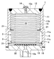
図1は本実施形態に係るアキュムレータの断面図であり、図2はそのアキュムレータが作動した状態の断面図であり、図3は図2の要部を拡大した拡大断面図である。
【0019】
本実施形態のアキュムレータは、図1に示すように、円筒状に形成されて軸方向の中間部に段部11a(ストッパ部)を有するシェル1と、シェル1の内部に一端が固定されて軸方向に伸縮自在に配設され、その外周部に取付けられたガイド部材21を有する金属ベローズ2と、金属ベローズ2の他端側開口を封止するように取付けられ、その外周部に取付けられた摺動部材31を有する可動板3と、可動板3に取付けられたシール部材4と、から構成されている。
【0020】
シェル1は、鉄系又はアルミニウム系合金を材質として両端が閉口した円筒状に形成されている。このシェル1は、円筒壁部11と、円筒壁部11の一端開口を閉塞する天井壁部12と、筒状部11の他端開口を閉塞する底壁部13とに分割形成され、それらが溶接で接合されることにより一体化されている。円筒壁部11の軸方向の略中央部には段部11aが設けられており、この段部11aの天井壁部12側には小径部11bが形成され、底壁部13側には大径部11cが形成されている。段部11aは、金属ベローズ2の所定以上(最小密着長以下)の収縮を阻止するストッパ部を形成している。天井壁部12の中央部には、金属ベローズ3の内側に形成されるガス室25にガスを導入するガス導入孔12aが設けられ、そのガス導入孔12aには止栓プラグ14がねじ止めされている。また、底壁部13の中央部には、シェル1の内部空間(油室15)と外部とを連通する油ポート13aが設けられている。
【0021】
金属ベローズ2は、約0.15mmの薄い鋼板により円筒蛇腹状に形成されており、軸方向に伸縮自在である。この金属ベローズ2は、停止した状態で、円筒壁部11の小径部11bの内径よりも少し小さく、円筒壁部11よりも少し短い大きさに形成されている。この金属ベローズ2は、その一端がシェル1の天井壁部12の内面に固定されて円筒壁部11の内側に同軸状に配置されている。この金属ベローズ2の略中央外周部で円筒壁部11の小径部11bと対向する部位には、アセタール樹脂製の複数のガイド部材21が周方向に距離を隔てて取付けられている。このガイド部材21は、金属ベローズ2とシェル1の円筒壁部11との接触を防止するものである。
【0022】
可動板3は、薄い金属板により円筒壁部11の大径部11cの内径よりも少し小さい円形に形成され、金属ベローズ2の他端にその開口を封止するように固着されている。これにより、金属ベローズ2の内側には、密閉されたガス室25が形成されており、このガス室25には、天井壁部12のガス導入孔12aを介して窒素ガスが封入されている。また、可動板3及び金属ベローズ2とシェル1の内面との間には、油ポート13aを介して外部と連通する油室15が形成されている。
【0023】
この可動板3の外周部には、円筒壁部11の大径部11cと摺動する摺動部材31が取付けられている。この摺動部材31は、摩擦係数が小さいアセタール樹脂でリング状に形成されており、可動板3の外周面に設けられた凹溝に嵌合固定されている。また、この可動板3の油ポート13aと対向する面には、油圧が負荷されていないときに、油室15の作動油が油ポート13へ全て流出するのを防止するゴム製の保護シール32が固着されている。
【0024】
シール部材4は、ゴムによりリング状に形成され、可動板3の天井壁部12側の面の外周部であって段部11aと対向する部位に加硫接着されている。このシール部材4は、金属ベローズ2が大きく収縮したときに段部11aに当接し、金属ベローズ2の所定以上(最小密着長以下)の収縮を阻止する。また、シール部材4が段部11aに当接しているときには、油室15内の作動油がシェル1の小径部11bと金属ベローズ2の間へ流入するのを阻止する。なお、このシール部材4及び保護シール32のゴム材料は、油室15に流入する作動油の種類によって適宜選択される。例えば鉱物油の場合は、NBR(ニトリルゴム)等が選択され、植物油(ブレーキ油)の場合は、IIR(ブチルゴム)やEPDM(エチレンプロピレン系ゴム)等が選択される。
【0025】
以上のように構成された本実施形態のアキュムレータは、油圧制御システムの油圧回路に油ポート13aが接続されて、油圧の蓄圧や脈動吸収に使用される。そして、突発的に油圧が大きく上昇したり、環境温度の低下に伴ってガス室の封入ガス圧が低下することにより、金属ベローズ2が大きく圧縮されると、図2及び図3に示すように、可動板3に設けられたシール部材4がシェル1の円筒壁部11の中央部に設けられた段部11aに当接することによって、金属ベローズ2の所定以上の収縮が阻止される。即ち、金属ベローズ2が最小密着長以下にまで圧縮される恐れは回避され、金属ベローズ2の山部(谷部)が潰されて座屈してしまうという事態が回避される。
【0026】
また、可動板3に設けられたシール部材4がシェル1の段部11aに当接した状態のときには、油室15内の作動油がシェル1の小径部11bと金属ベローズ2の間へ流入するのを阻止される。これにより、金属ベローズ2の外側の油圧は、それ以上に上昇しないので、金属ベローズ2の内側にあるガス室25の封入ガス圧と釣り合った状態を維持する。そのため、金属ベローズ2が油圧の上昇により潰されて変形してしまうという事態は回避される。
【0027】
以上のように、本実施形態のアキュムレータによれば、シェル1は、軸方向の中間部に金属ベローズ2の所定以上の収縮を阻止する段部11a(ストッパ部)を有し、可動板3は、段部11aに当接して油室15内の作動油がシェル1の小径部11bと金属ベローズ2の間へ流入するのを阻止するシール部材4を有するため、耐久性をより一層向上させることができる。
【0028】
また、金属ベローズ2の外周部には、金属ベローズ2とシェル1の小径部11bとの接触を防止するガイド部材21が取付けられているため、金属ベローズ2が伸縮するときにシェル1と接触しないので、金属ベローズ2の摩耗を防止することができ、耐久性が向上する。
【0029】
また、可動板3は、その外周部に取付けられてシェル1の大径部11cと摺動する摺動部材31を有するため、可動板3が金属ベローズ2の伸縮動作に連動する際に、摺動部材31がシェル1の大径部11cの内面に案内されて摺動することにより、可動板3が円滑に移動することができるため、金属ベローズ2の伸縮動作が安定して円滑に行われるようにすることができる。
【0030】
なお、本実施形態では、金属ベローズ2の所定以上の収縮を阻止するストッパ部として段部11aが設けられているが、この段部11aの代わりに、大径部11c側から小径部11b側に向かって次第に小径となるようなテーパ部を設けるようにしてもよい。
【図面の簡単な説明】
【図1】本発明の実施形態に係るアキュムレータの断面図である。
【図2】本発明の実施形態に係るアキュムレータが作動した状態の断面図である。
【図3】図2の要部を拡大した拡大断面図である。
【図4】従来のアキュムレータの断面図である。
【符号の説明】
1、101…シェル 11…円筒壁部
11a…段部(ストッパ部) 11b…小径部 11c…大径部
12…天井壁部 12a…ガス導入孔 13…底壁部
13a、113a…油ポート 14…止栓プラグ
15、115…油室 2、102…金属ベローズ
21…ガイド部材 25、125…ガス室 3、103…可動板
31…摺動部材 32、132…保護シール 4…シール部材[0001]
TECHNICAL FIELD OF THE INVENTION
The present invention relates to an accumulator used for accumulating hydraulic pressure and absorbing pulsation in a hydraulic control system such as a brake system or a hydro suspension of an automobile.
[0002]
[Prior art]
2. Description of the Related Art Conventionally, accumulators used for accumulating hydraulic pressure and absorbing pulsation include metal bellows as a separation membrane that separates the interior into a gas chamber and an oil chamber, as disclosed in Patent Documents 1 to 3, for example. Some have been used. As such an accumulator, as shown in FIG. 4, a cylindrical shell 101 having an oil port 113a, and one end thereof is fixed to the inner surface of a wall on one end side of the shell 101 so as to be axially extendable and contractable in the shell 101. A gas chamber 125 is formed inside the metal bellows 102 by sealing the opening at the other end of the metal bellows 102 and the oil chamber between the metal bellows 102 and the inner surface of the shell 101. One having a movable plate 103 forming the base 115 is known.
[0003]
When no hydraulic pressure is applied, the accumulator is stopped in a state where the metal bellows 102 is extended (the state in FIG. 4). In this state, when the pressure of the oil port 113a connected to the hydraulic circuit is higher than the pressure of the gas chamber 125, the movable plate 103 is pressed by the hydraulic oil flowing into the oil chamber 115 from the oil port 113a, and The metal bellows 102 is compressed so as to reduce the volume. Then, when the pressure of the oil port 113a becomes lower than the pressure of the gas chamber 125, the metal bellows 102 expands and returns to the original state so that the volume of the gas chamber 125 increases. In this manner, the metal bellows 102 repeatedly expands and contracts in response to the pressure change generated in the hydraulic circuit, and thereby accumulates hydraulic pressure and absorbs pulsation.
[0004]
In addition, when all the hydraulic oil staying between the metal bellows 102 and the shell 101 flows out when no oil pressure is applied, the metal bellows 102 is deformed by the gas pressure filled in the gas chamber 125. Therefore, in order to prevent this, a protective seal 132 is provided at a portion of the movable plate 103 facing the oil port 113a, so that all the hydraulic oil in the oil chamber 115 does not flow out. As a result, a state where the filled gas pressure and the oil pressure are always balanced is maintained.
[0005]
[Patent Document 1]
Japanese Patent Application Laid-Open No. 2002-70801 [Patent Document 2]
JP 2001-513724 A [Patent Document 3]
Japanese Patent No. 2539905 [0006]
[Problems to be solved by the invention]
By the way, at the time of actual use of the accumulator, the metal bellows 102 is greatly compressed due to a sudden increase in hydraulic pressure or a decrease in gas pressure in the gas chamber 125 due to a decrease in environmental temperature. There is a possibility that the metal bellows 102 is compressed to a length equal to or less than the minimum adhesion length (the length of a state in which the metal bellows 102 is compressed and adhered without plastic deformation). When the metal bellows 102 is compressed below the minimum adhesion length in this way, the peaks (valleys) of the metal bellows 102 are crushed and buckled. Will be reduced. In order to prevent this, if the maximum compression amount under the use condition is designed with a sufficient margin with respect to the minimum contact length, the length of the metal bellows 102 becomes long, and the accumulator becomes large.
[0007]
In this regard, in Patent Document 1 and Patent Document 2, a functional member provided to protrude in the axial direction inside the metal bellows 102 prevents compression of the metal bellows 102 greater than a predetermined value. This avoids an extreme decrease in durability. However, when the functional member prevents large compression of the metal bellows 102, it is when the oil pressure of the oil chamber 115 is greatly increased. There is a possibility that the oil pressure of 115 will increase further. Therefore, a situation occurs in which the metal bellows 102 is crushed and deformed by the raised oil pressure of the oil chamber 115, which causes a decrease in durability.
[0008]
The present invention has been made in view of the above situation, and an object of the present invention is to provide an accumulator capable of further improving durability.
[0009]
Means for Solving the Problems, Functions and Effects of the Invention
According to a first aspect of the present invention, there is provided a shell formed in a cylindrical shape, and one end of which is fixed to an inner surface of a wall on one end side of the shell and is disposed in the shell so as to be able to expand and contract in the axial direction. A movable plate that forms a gas chamber inside the metal bellows by sealing the opened end of the metal bellows and the other end of the metal bellows, and forms an oil chamber between the metal bellows and the inner surface of the shell. Wherein the shell has a stopper at an intermediate portion in the axial direction for preventing contraction of the metal bellows by a predetermined amount or more, and the movable plate abuts on the stopper to contact the oil chamber. Has a sealing member for preventing the hydraulic oil from flowing between the shell and the metal bellows.
[0010]
In the accumulator of the present invention, the metal bellows is provided on the movable plate when the metal bellows is greatly compressed due to a sudden increase in the hydraulic pressure suddenly or a decrease in the sealed gas pressure of the gas chamber accompanying a decrease in the environmental temperature. The metal bellows is prevented from contracting more than a predetermined amount by the contact of the seal member with the stopper provided at the intermediate portion of the shell. This avoids the risk that the metal bellows is compressed below the minimum contact length, and also avoids the situation where the peaks (valleys) of the metal bellows are crushed and buckled.
[0011]
Further, when the seal member provided on the movable plate is in contact with the stopper of the shell, the operating oil in the oil chamber is prevented from flowing between the shell and the metal bellows. As a result, the oil pressure outside the metal bellows does not rise any more, so that it maintains a state in which the gas pressure in the gas chamber inside the metal bellows is balanced. For this reason, a situation in which the metal bellows is crushed and deformed by an increase in hydraulic pressure is avoided.
[0012]
Therefore, according to the accumulator of the present invention, the durability can be further improved.
[0013]
An accumulator according to a second aspect of the present invention employs a means in which the metal bellows according to the first aspect of the present invention has a guide member attached to an outer peripheral portion thereof to prevent contact with the shell.
[0014]
According to this means, since the metal bellows does not come into contact with the shell when it expands and contracts, wear of the metal bellows can be prevented, and durability is improved. The guide member can be formed of a synthetic resin having a small coefficient of friction and excellent in heat resistance, oil resistance, and friction resistance. For example, acetal resin or nylon can be used.
[0015]
An accumulator according to a third aspect of the present invention employs the means according to the first or second aspect of the present invention, wherein the movable plate has a sliding member attached to an outer peripheral portion thereof and sliding with the shell. .
[0016]
According to this means, when the movable plate is linked to the expansion and contraction operation of the metal bellows, the sliding member is guided by the inner surface of the shell and slides, so that the movable plate can move smoothly. The expansion and contraction operation of the bellows can be performed stably and smoothly. Like the guide member, this sliding member can be formed of a synthetic resin having a small coefficient of friction and excellent in heat resistance, oil resistance, and friction resistance. For example, acetal resin or nylon can be used.
[0017]
BEST MODE FOR CARRYING OUT THE INVENTION
Hereinafter, embodiments of the present invention will be described with reference to the drawings.
[0018]
FIG. 1 is a cross-sectional view of the accumulator according to the present embodiment, FIG. 2 is a cross-sectional view in a state where the accumulator is operated, and FIG. 3 is an enlarged cross-sectional view in which main parts of FIG. 2 are enlarged.
[0019]
As shown in FIG. 1, the accumulator according to the present embodiment includes a shell 1 that is formed in a cylindrical shape and has a stepped portion 11 a (stopper portion) at an intermediate portion in an axial direction, and a shaft having one end fixed inside the shell 1. A metal bellows 2 having a guide member 21 attached to the outer peripheral portion thereof, which is provided so as to be able to expand and contract in the direction, is mounted so as to seal the other end side opening of the metal bellows 2, and is mounted on the outer peripheral portion. It comprises a movable plate 3 having a sliding member 31 and a seal member 4 attached to the movable plate 3.
[0020]
The shell 1 is made of an iron-based or aluminum-based alloy and is formed in a cylindrical shape with both ends closed. The shell 1 is divided into a cylindrical wall portion 11, a ceiling wall portion 12 closing one end opening of the cylindrical wall portion 11, and a bottom wall portion 13 closing the other end opening of the cylindrical portion 11. They are integrated by welding. A step portion 11a is provided at a substantially central portion of the cylindrical wall portion 11 in the axial direction. A small diameter portion 11b is formed on the ceiling wall portion 12 side of the step portion 11a, and a large diameter portion is formed on the bottom wall portion 13 side. The part 11c is formed. The step portion 11a forms a stopper portion for preventing the metal bellows 2 from shrinking more than a predetermined value (less than the minimum contact length). A gas introduction hole 12a for introducing gas into a gas chamber 25 formed inside the metal bellows 3 is provided at a central portion of the ceiling wall portion 12, and a stopper plug 14 is screwed into the gas introduction hole 12a. ing. An oil port 13a is provided at the center of the bottom wall portion 13 to communicate the internal space (oil chamber 15) of the shell 1 with the outside.
[0021]
The metal bellows 2 is formed in a cylindrical bellows shape by a thin steel plate having a thickness of about 0.15 mm, and is capable of extending and contracting in the axial direction. The metal bellows 2 is formed to be slightly smaller than the inner diameter of the small diameter portion 11b of the cylindrical wall portion 11 and slightly shorter than the cylindrical wall portion 11 in the stopped state. One end of the metal bellows 2 is fixed to the inner surface of the ceiling wall 12 of the shell 1, and is arranged coaxially inside the cylindrical wall 11. A plurality of guide members 21 made of acetal resin are attached to a portion of the metal bellows 2 at a substantially central outer peripheral portion facing the small diameter portion 11b of the cylindrical wall portion 11 at a distance in the circumferential direction. The guide member 21 prevents the contact between the metal bellows 2 and the cylindrical wall portion 11 of the shell 1.
[0022]
The movable plate 3 is formed of a thin metal plate into a circular shape slightly smaller than the inner diameter of the large-diameter portion 11c of the cylindrical wall portion 11, and is fixed to the other end of the metal bellows 2 so as to seal its opening. Thus, a sealed gas chamber 25 is formed inside the metal bellows 2, and the gas chamber 25 is filled with nitrogen gas through the gas introduction hole 12 a of the ceiling wall 12. An oil chamber 15 communicating with the outside via an oil port 13a is formed between the movable plate 3 and the metal bellows 2 and the inner surface of the shell 1.
[0023]
A sliding member 31 that slides on the large-diameter portion 11c of the cylindrical wall portion 11 is attached to the outer peripheral portion of the movable plate 3. The sliding member 31 is formed of an acetal resin having a small coefficient of friction in a ring shape, and is fitted and fixed in a concave groove provided on the outer peripheral surface of the movable plate 3. On the surface of the movable plate 3 opposed to the oil port 13a, a rubber protection seal 32 for preventing all of the hydraulic oil in the oil chamber 15 from flowing out to the oil port 13 when no oil pressure is applied. Is fixed.
[0024]
The seal member 4 is formed in a ring shape from rubber, and is vulcanized and bonded to a portion of the outer surface of the surface of the movable plate 3 on the side of the ceiling wall portion 12 facing the step portion 11a. The seal member 4 comes into contact with the step 11a when the metal bellows 2 contracts greatly, and prevents the metal bellows 2 from contracting more than a predetermined amount (less than the minimum contact length). Further, when the seal member 4 is in contact with the step portion 11a, the operation oil in the oil chamber 15 is prevented from flowing between the small diameter portion 11b of the shell 1 and the metal bellows 2. The rubber material of the seal member 4 and the protective seal 32 is appropriately selected according to the type of hydraulic oil flowing into the oil chamber 15. For example, in the case of mineral oil, NBR (nitrile rubber) and the like are selected, and in the case of vegetable oil (brake oil), IIR (butyl rubber) and EPDM (ethylene propylene rubber) are selected.
[0025]
In the accumulator of the present embodiment configured as described above, the oil port 13a is connected to the hydraulic circuit of the hydraulic control system, and is used for accumulating hydraulic pressure and absorbing pulsation. When the metal bellows 2 is largely compressed due to a sudden increase in the hydraulic pressure or a decrease in the gas pressure in the gas chamber due to a decrease in the environmental temperature, as shown in FIGS. Since the sealing member 4 provided on the movable plate 3 abuts on the step 11a provided at the center of the cylindrical wall portion 11 of the shell 1, the metal bellows 2 is prevented from contracting more than a predetermined amount. That is, the risk that the metal bellows 2 is compressed to a value equal to or less than the minimum adhesion length is avoided, and the situation where the peaks (valleys) of the metal bellows 2 are crushed and buckled is avoided.
[0026]
When the sealing member 4 provided on the movable plate 3 is in contact with the step 11a of the shell 1, the hydraulic oil in the oil chamber 15 flows between the small diameter portion 11b of the shell 1 and the metal bellows 2. Is prevented. As a result, the oil pressure outside the metal bellows 2 does not rise any more, so that the gas pressure in the gas chamber 25 inside the metal bellows 2 is maintained in a balanced state. Therefore, a situation in which the metal bellows 2 is crushed and deformed due to an increase in hydraulic pressure is avoided.
[0027]
As described above, according to the accumulator of the present embodiment, the shell 1 has the step portion 11a (stopper portion) for preventing the metal bellows 2 from contracting by a predetermined amount or more in the axial middle portion. And the seal member 4 which abuts the step portion 11a and prevents the hydraulic oil in the oil chamber 15 from flowing between the small diameter portion 11b of the shell 1 and the metal bellows 2, thereby further improving the durability. Can be.
[0028]
Further, a guide member 21 for preventing contact between the metal bellows 2 and the small-diameter portion 11b of the shell 1 is attached to the outer peripheral portion of the metal bellows 2, so that the metal bellows 2 does not contact the shell 1 when it expands and contracts. Therefore, wear of the metal bellows 2 can be prevented, and durability is improved.
[0029]
Further, since the movable plate 3 has the sliding member 31 attached to the outer peripheral portion thereof and sliding with the large-diameter portion 11c of the shell 1, when the movable plate 3 is interlocked with the expansion and contraction operation of the metal bellows 2, The movable member 3 is guided and slid by the inner surface of the large-diameter portion 11c of the shell 1 so that the movable plate 3 can move smoothly, so that the expansion and contraction operation of the metal bellows 2 is performed stably and smoothly. You can do so.
[0030]
In this embodiment, the step portion 11a is provided as a stopper portion for preventing the metal bellows 2 from shrinking more than a predetermined amount. However, instead of the step portion 11a, from the large-diameter portion 11c side to the small-diameter portion 11b side. A tapered portion having a gradually decreasing diameter may be provided.
[Brief description of the drawings]
FIG. 1 is a sectional view of an accumulator according to an embodiment of the present invention.
FIG. 2 is a cross-sectional view illustrating a state where an accumulator according to the embodiment of the present invention is operated.
FIG. 3 is an enlarged cross-sectional view showing an enlarged main part of FIG. 2;
FIG. 4 is a sectional view of a conventional accumulator.
[Explanation of symbols]
DESCRIPTION OF SYMBOLS 1, 101 ... Shell 11 ... Cylindrical wall part 11a ... Step part (stopper part) 11b ... Small diameter part 11c ... Large diameter part 12 ... Ceiling wall part 12a ... Gas introduction hole 13 ... Bottom wall part 13a, 113a ... Oil port 14 ... Stopper plugs 15, 115 ... Oil chamber 2, 102 ... Metal bellows 21 ... Guide member 25, 125 ... Gas chamber 3, 103 ... Movable plate 31 ... Sliding member 32, 132 ... Protective seal 4 ... Seal member