【0001】
【発明の属する技術分野】
本発明は、気化式の加湿器に関するものである。
【0002】
【従来の技術】
従来のこの種の気化式加湿器は、例えば図7に示すような構造のものが一般に知られている。
【0003】
すなわち、1は横長箱型の加湿器本体、2は本体1内の下部に設けられた水槽で、カートリッジ式の給水用水タンク3等によって給水される。
【0004】
4は加湿ドラムで、外周にウレタンフォーム(発泡体)円筒状の加湿フィルター5を装着し、一方を閉じた閉止部6とし、他方を開口部7とし、中心軸8で本体1に回転軸としてささえられ、加湿フィルター5の下部を水槽2の水面下に浸漬させている。
【0005】
9はギヤモーターで、加湿ドラム4を回転させる駆動軸を有し、加湿ドラム4の中心軸8を回転させる。
【0006】
10は本体1内に配設された送風装置で、水槽2内の加湿ドラム4の開口部7から内部に送風する。
【0007】
11は中心軸8に取付けられた風向体で、加湿フィルター5の表面から出る空気の風速が弱まる点から閉止部6まで加湿ドラム4のほぼ内径に沿うように円錐状に形成されている。
【0008】
その動作は、まず、給水用水タンク3から水槽2に水が供給され、水槽2内の水は一定の水位に保たれ、その水位に浸るように加湿ドラム4が回転し、周囲に取付けた加湿フィルター5は発泡体であるため、その空泡部に水滴が付着したり、膜ができたりして水を含んだ状態となる。
【0009】
次に、送風機10を駆動して加湿ドラム4の開口部7から内部に送風すると、空気は加湿フィルター5を通過して外部に吹き出される。
【0010】
加湿ドラム4の中を空気が通過すると、加湿フィルター5内の水滴や膜が壊れ加湿しなくなるが、加湿フィルター5は加湿ドラム4の回転により再び水を含んだ状態となる。
【0011】
したがって、加湿ドラム4の内部に送風された空気は風向体11に沿って加湿フィルター5を通過し、加湿フィルター5の表面から湿った空気が吹き出され、これが室内に放出されて室内を加湿する(例えば特許文献1参照)。
【0012】
しかしながら、上記の従来技術において、加湿フィルター5は、ウレタンを発泡させ、その発泡で出来た空泡部を利用して加湿フィルター5を一度水没させることにより空泡に水滴を保持したり、膜を作り、この状態の中に風を通すことにより、風は水滴を破壊したり膜を破って風を湿潤させているものであった。
【0013】
このため、風が一度通過するとその後の風は素通りして加湿効率が悪くなるため、所定の加湿量を確保するには、本体を大きくし、加湿フィルターを大きくするとともに風の量を増す等の対応をする必要があった。
【0014】
ところで、近年では軽量で、かつコンパクト化が要求されており、図5〜図6に示すような構造のものが提案されている。
【0015】
すなわち、水槽部36と、この水槽部36に一定量の水を供給する給水用水タンク23と、室内の乾燥した空気を取入れる吸込口32と、室内に湿った空気を送る吹出口33と、両口間を連絡する風路中に配設された送風装置30と、この送風装置30の出口側に配設され、支持枠35に収納されたヒータ34と、小穴の明いた吸水性の良いシート状の素材をプリーツ折りして形成され、下部を水槽部36内の水に浸漬した気化フィルター37とで構成したものである。
【0016】
次に、その動作について説明する。
【0017】
送風装置30によって吸込口32から吸込まれた室内の乾燥した空気は、支持枠35に収納されたヒータ34を通過させて加熱した後、水槽部36の水により湿潤した気化フィルター34を通過させ、吹出口33から吹き出されて室内を加湿するものである。
【0018】
【特許文献1】
実開昭56−21138号公報
【0019】
【発明が解決しようとする課題】
しかしながら、上記の従来技術において、後者に示すものはコンパクト化を追求する余り、空気の速度が速く、また複雑な空気の流れがある送風装置30の出口側に、支持枠35に収納されたヒータ34を配設することは、該部分の空気の通過抵抗が大きく、また複雑な風の流れがあることにより風がヒータ34および支持枠35に当り、異常音が発生するという問題があった。
【0020】
【課題を解決するための手段】
本発明は上記の問題点を解決するためになされたものであり、水槽部と、この水槽部に一定量の水を供給する給水用水タンクと、室内の乾燥した空気を取入れる吸込口と、室内に湿った空気を送る吹出口と、両口間を連絡する風路中に配設された送風装置と、この送風装置の出口側に配設されたヒータと、このヒータを収納する支持枠と、小穴の明いた吸水性の良いシート状の素材をプリーツ折りして形成され、下部を水槽部内の水に浸漬した気化フィルターとにより構成され、送風装置によって吸込口から吸い込まれた室内の乾燥した空気をヒータを通過させて加熱した後、水槽部の水により湿潤した気化フィルターを通過させ、吹出口から吹き出すようにした加湿器において、前記ヒータを収納する支持枠の周囲に複数の穴を穿設したものである。
【0021】
これによって、複雑な風の流れがある送風装置の出口側にヒータを配設しても送風装置からの空気は、一部は穴を通りヒータ周囲を経由して気化フィルター側へ、他の一部は直接気化フィルター側へ流れることで支持枠の通過抵抗は、それ程大きくはなく、空気量の低下は防止できる。
【0022】
又、該部分の複雑な空気の流れの中に支持枠が存在しても、支持枠に穿設した穴により、空気の流れを妨げるものがなく、空気の衝突により発生する異常音もなくすことができる。
【0023】
【発明の実施の形態】
以下本発明の一実施例を図1〜図4を参照して説明する。
【0024】
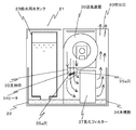
図において、21は本体、22はこの本体21内の下部に配設された水槽、36は水槽22の横に並べて配設された水槽部で、両者は樹脂で一体に成形され、ともに底部で連なって同一レベルの水を貯水する。
【0025】
32は室内の乾燥した空気を本体21内に取入れる吸込口で、本体21の側面に開口している。
【0026】
33は室内に湿った空気を送る吹出口で、本体21の上面に開口している。
【0027】
30は吸込口32から吹出口33に至る風路中に配設された送風装置で、この出口側には、図3に示すように全面に小穴37aが明けられた吸水性の良いシート状の素材をプリーツ折りした横長方形の気化フィルター37が配設され、その下部は水槽部36内の水に浸漬されている。
【0028】
34は、送風装置30の出口側近傍に配設された空気を加熱するヒータ、35はこのヒータ34を収納する支持枠で、上下面が開口し、周囲に図4に示すように複数の穴35aが穿設されている。
【0029】
以上の構成による動作を以下説明する。
【0030】
加湿器を運転する際に、給水用水タンク23に水を入れ、水槽22に設置することにより水槽部36には一定水量の水が流れ出し、気化フィルター37の下部を水没させる。従って、気化フィルター37は水を吸上げ湿潤する。
【0031】
このような状態で送風装置30を駆動することにより、吸込口32から取入れられた室内の乾燥した空気は、送風装置30の出口側に配設されたヒータ34により加熱される。
【0032】
次に、加熱された空気は、下部を水槽部36の水に水没させることで湿潤した気化フィルター37を通過し、気化フィルター37内の吸水した水を気化させるとともに吹出口33へ吹き込まれ、該吹出口33から室内に放出される。
【0033】
ここで、複雑な空気の流れがある送風装置30の出口側にヒータ34及び支持枠35が配設されているが、支持枠35には穴35aが複数穿設してあることから、ヒータ34及び支持枠35を通る風は穴35aも通り抜けることが出来、支持枠35による空気の流れ方向が変えられることなくスムーズに流れるため、空気の通過抵抗の増大化が抑制でき、また空気の支持枠35への衝突による異常音の発生がない。
【0034】
【発明の効果】
以上説明したように、本発明は、送風装置の空気の出口側に配設されたヒータを収納する支持枠に複数の穴を穿設することにより、支持枠を通過する空気の通過抵抗の増大化が抑制できる。
【0035】
また、送風装置からの空気が支持枠へ衝突することにより発生する異常音をなくすことができる。
【0036】
そして、前記したヒータ支持枠を採用することによって、異常音が発生することがない軽量でコンパクトな加湿器を提供できる。
【図面の簡単な説明】
【図1】本発明の一実施例を示す加湿器の概略正面断面図である。
【図2】同じく概略側面断面図である。
【図3】同じく気化フィルターの斜視図である。
【図4】同じく支持枠の斜視図である。
【図5】従来例の概略正面断面図である。
【図6】同じく概略側面断面図である。
【図7】従来例の概略正面断面図である。
【符号の説明】
23 給水用水タンク
30 送風装置
32 吸込口
33 吹出口
34 ヒータ
35 支持枠
35a 穴
36 水槽部
37 気化フィルター[0001]
TECHNICAL FIELD OF THE INVENTION
The present invention relates to a vaporizing humidifier.
[0002]
[Prior art]
As this type of conventional evaporative humidifier, for example, one having a structure as shown in FIG. 7 is generally known.
[0003]
That is, 1 is a horizontal box-shaped humidifier main body, 2 is a water tank provided in a lower part in the main body 1, and water is supplied by a cartridge type water supply water tank 3 or the like.
[0004]
Reference numeral 4 denotes a humidifying drum, which is provided with a urethane foam (foam) cylindrical humidifying filter 5 on the outer periphery, one of which is a closed portion 6, the other is an opening 7, and the central axis 8 is used as a rotation axis for the main body 1. The lower part of the humidifying filter 5 is immersed below the surface of the water tank 2.
[0005]
Reference numeral 9 denotes a gear motor, which has a drive shaft for rotating the humidifying drum 4 and rotates a central shaft 8 of the humidifying drum 4.
[0006]
Reference numeral 10 denotes a blower disposed in the main body 1, and blows air from the opening 7 of the humidifying drum 4 in the water tank 2.
[0007]
Reference numeral 11 denotes a wind direction body attached to the central shaft 8, which is formed in a conical shape so as to substantially follow the inner diameter of the humidification drum 4 from the point at which the wind speed of the air flowing out of the surface of the humidification filter 5 is weakened to the closing portion 6.
[0008]
The operation is as follows. First, water is supplied from the water supply water tank 3 to the water tank 2, the water in the water tank 2 is maintained at a constant water level, the humidification drum 4 rotates so as to be immersed in the water level, and Since the filter 5 is a foam, a water droplet is attached to the empty bubble portion or a film is formed, so that the filter 5 contains water.
[0009]
Next, when the blower 10 is driven to blow air from the opening 7 of the humidifying drum 4 to the inside, the air passes through the humidifying filter 5 and is blown out.
[0010]
When the air passes through the humidification drum 4, water droplets and films in the humidification filter 5 are broken and humidification stops, but the humidification filter 5 is again in a state of containing water by rotation of the humidification drum 4.
[0011]
Therefore, the air blown into the humidification drum 4 passes through the humidification filter 5 along the wind direction member 11, and the humid air is blown out from the surface of the humidification filter 5, and is discharged into the room to humidify the room ( See, for example, Patent Document 1.
[0012]
However, in the above-mentioned conventional technology, the humidifying filter 5 foams urethane, and once immerses the humidifying filter 5 using the air bubbles formed by the foaming, retains water droplets in the air bubbles, or removes the film. By making and passing air through this condition, the wind destroyed the water droplets and broke the membrane, moistening the wind.
[0013]
For this reason, once the wind passes, the subsequent wind passes and the humidification efficiency deteriorates.Therefore, in order to secure a predetermined humidification amount, it is necessary to enlarge the main body, enlarge the humidification filter and increase the amount of wind, etc. We needed to take action.
[0014]
By the way, in recent years, it is required to be lightweight and compact, and a structure as shown in FIGS. 5 and 6 has been proposed.
[0015]
That is, a water tank portion 36, a water supply water tank 23 that supplies a fixed amount of water to the water tank portion 36, a suction port 32 that takes in dry air in the room, and an outlet 33 that sends moist air into the room, A blower 30 disposed in an air passage communicating between the two openings, a heater 34 disposed on an outlet side of the blower 30 and housed in a support frame 35, and a water absorbent having a small hole and good water absorption. It is formed by pleating a sheet-like material, and has a lower portion composed of a vaporizing filter 37 immersed in water in a water tank portion 36.
[0016]
Next, the operation will be described.
[0017]
The dried air in the room sucked from the suction port 32 by the blower 30 is heated by passing through a heater 34 accommodated in a support frame 35, and then passed through a vaporization filter 34 moistened with water in a water tank 36, The air is blown out from the air outlet 33 to humidify the room.
[0018]
[Patent Document 1]
Japanese Utility Model Publication No. 56-21138
[Problems to be solved by the invention]
However, in the above-mentioned prior art, the latter one has a high air velocity and a heater housed in the support frame 35 at the outlet side of the blower 30 where there is a complicated air flow, in order to pursue compactness. The arrangement of 34 has a problem in that the passage resistance of the air in the portion is large, and the presence of a complicated flow of the wind causes the wind to hit the heater 34 and the support frame 35 to generate an abnormal sound.
[0020]
[Means for Solving the Problems]
The present invention has been made in order to solve the above problems, a water tank, a water supply water tank that supplies a certain amount of water to the water tank, a suction port that takes in the indoor dry air, An outlet for sending humid air into a room, a blower provided in an air passage communicating between the two openings, a heater provided on the outlet side of the blower, and a support frame for housing the heater And a vaporizing filter formed by pleating a water-absorbent sheet-like material with a small hole and immersing the lower part in the water in the water tank. The heated air is heated by passing through a heater, and then passed through a vaporization filter moistened with water in a water tank section, and in a humidifier that is blown out from an outlet, a plurality of holes are provided around a support frame for housing the heater. Also drilled It is.
[0021]
As a result, even if a heater is arranged on the outlet side of the blower where there is a complicated flow of air, part of the air from the blower passes through the hole and passes around the heater to the vaporization filter side, and the other air Since the portion flows directly to the vaporization filter side, the passage resistance of the support frame is not so large, and a decrease in the amount of air can be prevented.
[0022]
In addition, even if the support frame exists in the complicated air flow of the part, there is no obstacle to the air flow due to the holes formed in the support frame, and there is no abnormal sound generated by the air collision. Can be.
[0023]
BEST MODE FOR CARRYING OUT THE INVENTION
An embodiment of the present invention will be described below with reference to FIGS.
[0024]
In the figure, reference numeral 21 denotes a main body, 22 denotes a water tank disposed at a lower portion in the main body 21, and 36 denotes a water tank portion arranged side by side with the water tank 22, both of which are integrally formed of resin, and both are formed at the bottom. The same level of water is stored in a row.
[0025]
Reference numeral 32 denotes a suction port for taking in indoor dry air into the main body 21, and is opened on a side surface of the main body 21.
[0026]
Reference numeral 33 denotes an outlet for sending humid air into the room, which is opened on the upper surface of the main body 21.
[0027]
Reference numeral 30 denotes a blower disposed in an air passage extending from the inlet 32 to the outlet 33. On the outlet side, as shown in FIG. A vaporizing filter 37 of a horizontal rectangular shape obtained by pleating a material is provided, and the lower part thereof is immersed in water in a water tank portion 36.
[0028]
Numeral 34 denotes a heater for heating the air disposed near the outlet side of the blower 30. Numeral 35 denotes a support frame for accommodating the heater 34, the upper and lower surfaces of which are open, and a plurality of holes as shown in FIG. 35a is drilled.
[0029]
The operation of the above configuration will be described below.
[0030]
When the humidifier is operated, water is poured into the water supply water tank 23 and is set in the water tank 22, whereby a certain amount of water flows into the water tank part 36, and the lower part of the vaporization filter 37 is submerged. Therefore, the vaporization filter 37 absorbs water and becomes wet.
[0031]
By driving the air blower 30 in such a state, the dry air in the room taken in from the inlet 32 is heated by the heater 34 arranged on the outlet side of the air blower 30.
[0032]
Next, the heated air passes through the vaporization filter 37 moistened by submerging the lower part of the water in the water tank section 36, vaporizes the water absorbed in the vaporization filter 37, and is blown into the outlet 33. The air is discharged from the outlet 33 into the room.
[0033]
Here, the heater 34 and the support frame 35 are disposed on the outlet side of the blower 30 where there is a complicated air flow, but since the support frame 35 has a plurality of holes 35a, the heater 34 and the support frame 35 are provided. Further, the wind passing through the support frame 35 can also pass through the hole 35a and smoothly flow without changing the flow direction of the air by the support frame 35, so that it is possible to suppress an increase in air passage resistance, and also to support the air support frame. No abnormal sound is generated due to the collision with 35.
[0034]
【The invention's effect】
As described above, the present invention increases the passage resistance of the air passing through the support frame by forming a plurality of holes in the support frame for housing the heater disposed on the air outlet side of the blower. Can be suppressed.
[0035]
In addition, it is possible to eliminate abnormal noise generated when air from the blower collides with the support frame.
[0036]
In addition, by employing the above-described heater support frame, a lightweight and compact humidifier that does not generate abnormal noise can be provided.
[Brief description of the drawings]
FIG. 1 is a schematic front sectional view of a humidifier showing one embodiment of the present invention.
FIG. 2 is a schematic side sectional view of the same.
FIG. 3 is a perspective view of the vaporization filter.
FIG. 4 is a perspective view of the support frame.
FIG. 5 is a schematic front sectional view of a conventional example.
FIG. 6 is a schematic side sectional view of the same.
FIG. 7 is a schematic front sectional view of a conventional example.
[Explanation of symbols]
23 Water supply water tank 30 Blower 32 Suction port 33 Outlet port 34 Heater 35 Support frame 35a Hole 36 Water tank section 37 Vaporization filter