JP2004232995A - Refrigeration cycle device - Google Patents
Refrigeration cycle device Download PDFInfo
- Publication number
- JP2004232995A JP2004232995A JP2003023940A JP2003023940A JP2004232995A JP 2004232995 A JP2004232995 A JP 2004232995A JP 2003023940 A JP2003023940 A JP 2003023940A JP 2003023940 A JP2003023940 A JP 2003023940A JP 2004232995 A JP2004232995 A JP 2004232995A
- Authority
- JP
- Japan
- Prior art keywords
- evaporator
- temperature
- compressor
- refrigerant
- flow rate
- Prior art date
- Legal status (The legal status is an assumption and is not a legal conclusion. Google has not performed a legal analysis and makes no representation as to the accuracy of the status listed.)
- Granted
Links
Images
Landscapes
- Air-Conditioning For Vehicles (AREA)
Abstract
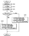
【課題】可変容量型圧縮機や電動圧縮機のように吐出冷媒流量を外部からの制御信号により制御可能な構成になっている圧縮機を備える冷凍サイクル装置において、冷媒小流量時における蒸発器吹出空気温度のバラツキを低減する。
【解決手段】吐出容量を外部からの制御信号により制御可能な圧縮機を有し、蒸発器の空気吹出側のうち、冷媒小流量時に蒸発器温度が高温となる高温側領域に第1温度センサを、冷媒小流量時に蒸発器温度が低温となる低温側領域に第2温度センサをそれぞれ配置し、第1、第2温度センサにより検出される蒸発器温度Te1、Te2を比較し(S130)、高い方の蒸発器温度と目標蒸発器温度とに基づいて圧縮機の吐出容量を制御する(S140、S150)。
【選択図】 図5An evaporator blowout at a small refrigerant flow rate in a refrigeration cycle apparatus including a compressor such as a variable displacement compressor or an electric compressor having a configuration in which the discharge refrigerant flow rate can be controlled by an external control signal. Reduce variations in air temperature.
A first temperature sensor includes a compressor capable of controlling a discharge capacity by an external control signal, and a first temperature sensor in a high temperature side region of the air blowing side of the evaporator where the temperature of the evaporator becomes high when the refrigerant has a small flow rate. The second temperature sensors are respectively arranged in the low temperature side region where the evaporator temperature becomes low at the time of the small flow rate of the refrigerant, and the evaporator temperatures Te1 and Te2 detected by the first and second temperature sensors are compared (S130). The discharge capacity of the compressor is controlled based on the higher evaporator temperature and the target evaporator temperature (S140, S150).
[Selection diagram] FIG.
Description
【0001】
【発明の属する技術分野】
本発明は可変容量型圧縮機や電動圧縮機のように吐出冷媒流量を外部からの制御信号により制御可能な構成になっている圧縮機を備える冷凍サイクル装置に関するもので、車両用空調装置に用いて好適である。
【0002】
【従来の技術】
従来、車両用空調装置においては、冷凍サイクル装置の圧縮機を車両エンジンにより駆動しているので、固定容量型圧縮機の作動を電磁クラッチにより断続して圧縮機の能力を行っている。しかし、圧縮機作動の断続制御に伴ってショックや騒音が発生し、車両の走行フィーリングを悪化させる。
【0003】
そこで、近年では、吐出容量を外部からの制御信号により制御可能な可変容量型圧縮機が採用されるようになっている。この可変容量型圧縮機では吐出容量を連続的にきめ細かく変化できるので、車両の走行フィーリングを改善できる。
【0004】
この吐出容量の制御を具体的に述べると、冷凍サイクル装置に装備される蒸発器の実際の吹出温度Teと目標蒸発器温度TEOとの偏差を算出し、この偏差に基づいて圧縮機の容量制御電流を算出し、この容量制御電流を圧縮機の容量可変装置に出力して、圧縮機の吐出容量を制御している。これにより、蒸発器への冷媒流量を増減して蒸発器冷却能力を増減し、蒸発器吹出温度Teが目標蒸発器温度TEO付近に維持されるようにしている。
【0005】
【発明が解決しようとする課題】
ところで、春秋の中間期のように冷房熱負荷が低いときは蒸発器吸い込み空気温度が低くなる。しかも、目標蒸発器温度TEOは圧縮機駆動動力の節減のために冷房高負荷時よりも高めの温度に変更される。この結果、蒸発器の必要冷却能力が小さくなるので、圧縮機の吐出容量は小容量に制御され、蒸発器循環冷媒流量が小流量となる。
【0006】
このような冷媒小流量時には、蒸発器の冷媒入口部と冷媒出口部間の冷媒流路における液冷媒の分布に不均一が起こりやすくなり、蒸発器吹出空気温度のバラツキが大きくなるという不具合を生じる。
【0007】
なお、本発明者らの検討によると、圧縮機として可変容量型圧縮機の代わりに、回転数制御により吐出冷媒流量を制御可能な電動圧縮機を使用する冷凍サイクル装置においても、冷媒小流量時に蒸発器吹出空気温度のバラツキが大きくなるという不具合が同様に生じることを確認している。
【0008】
本発明は上記点に鑑みて、可変容量型圧縮機や電動圧縮機のように吐出冷媒流量を外部からの制御信号により制御可能な構成になっている圧縮機を備える冷凍サイクル装置において、冷媒小流量時における蒸発器吹出空気温度のバラツキを低減することを目的とする。
【0009】
【課題を解決するための手段】
上記目的を達成するため、請求項1に記載の発明では、吐出冷媒流量を外部からの制御信号により制御可能な構成になっている圧縮機(11)と、圧縮機(11)の吸入側に接続され、低圧冷媒を蒸発させる蒸発器(9)と、蒸発器(9)の空気吹出側のうち、冷媒小流量時に蒸発器温度が高温となる高温側領域に配置された第1蒸発器温度検出手段(41a)と、蒸発器(9)の空気吹出側のうち、冷媒小流量時に蒸発器温度が低温となる低温側領域に配置された第2蒸発器温度検出手段(41b)と、第1蒸発器温度検出手段(41a)および第2蒸発器温度検出手段(41b)の検出信号が入力され、圧縮機(11)の吐出冷媒流量を制御する制御手段(40)とを備え、
第1蒸発器温度検出手段(41a)および第2蒸発器温度検出手段(41b)により検出される蒸発器温度のうち、高い方の蒸発器温度と目標蒸発器温度とに基づいて、圧縮機(11)の吐出冷媒流量を制御することを特徴とする。
【0010】
これによると、冷媒小流量時に蒸発器冷媒流路における液冷媒の分布の不均一により蒸発器温度のバラツキが発生しても、この温度バラツキの高温側領域と低温側領域の蒸発器温度のうち、高温側領域の蒸発器温度が目標蒸発器温度となるように圧縮機(11)の吐出冷媒流量を制御することができる。
【0011】
従って、冷媒小流量時に高温側領域の蒸発器温度が低温側領域に比較して大きく上昇することを抑制して、蒸発器吹出空気温度のバラツキ増大による空調フィーリングの悪化を抑制できる。
【0012】
請求項2に記載の発明では、請求項1において、第1蒸発器温度検出手段(41a)および第2蒸発器温度検出手段(41b)により検出される蒸発器温度のうち、低い方の蒸発器温度が所定のフロスト判定温度まで低下すると、圧縮機(11)を吐出冷媒流量が略0となる状態に制御することを特徴とする。
【0013】
これにより、蒸発器(9)のフロスト進行を確実に防止できる。
【0014】
請求項3に記載の発明のように、請求項1または2において、目標蒸発器温度は、具体的には、少なくとも室内へ吹き出す空気の目標吹出温度と外気温に基づいて決定できる。
【0015】
請求項4に記載の発明のように、請求項1ないし3のいずれか1つにおいて、圧縮機(11)は、具体的には、吐出容量を変更可能な可変容量型圧縮機で構成でき、吐出容量を変更することにより吐出冷媒流量を変更できる。
【0016】
請求項5に記載の発明のように、請求項1ないし3のいずれか1つにおいて、圧縮機(11)として、具体的には、モータ(11c)により駆動される電動圧縮機を用いてもよく、モータ(11c)の回転数制御により吐出冷媒流量を変更することができる。
【0017】
なお、上記各手段の括弧内の符号は、後述する実施形態に記載の具体的手段との対応関係を示すものである。
【0018】
【発明の実施の形態】
(第1実施形態)
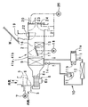
図1は第1実施形態の全体構成の概要を示すもので、車両用空調装置は車室内最前部の計器盤(図示せず)の内側部に配設される空調ユニット1を備えている。この空調ユニット1はケース2を有し、このケース2内に車室内へ向かって空気が送風される空気通路を構成する。このケース2の空気通路の最上流部に内気導入口3および外気導入口4を有する内外気切替箱5を配置している。この内外気切替箱5内に、内外気切替手段としての内外気切替ドア6を回転自在に配置している。
【0019】
この内外気切替ドア6はサーボモータ7によって駆動されるもので、内気導入口3より内気(車室内空気)を導入する内気導入モードと外気導入口4より外気(車室外空気)を導入する外気導入モードとを切り替える。
【0020】
内外気切替箱5の下流側には車室内に向かう空気流を発生させる電動式の送風機8を配置している。この送風機8は、遠心式の送風ファン8aをモータ8bにより駆動するようになっている。送風機8の下流側にはケース2内を流れる空気を冷却する蒸発器9を配置している。この蒸発器9は、送風機8の送風空気を冷却する冷房用熱交換器であって、冷凍サイクル10を構成する要素の一つである。
【0021】
なお、冷凍サイクル10は、圧縮機11の吐出側から、凝縮器12、受液器13および減圧手段をなす膨張弁14を介して蒸発器9に冷媒が循環するように構成された周知のものである。
【0022】
圧縮機11は、電磁クラッチ11a、ベルト等を介して車両エンジン(図示せず)の回転動力が伝達されることにより回転駆動される。また、この圧縮機11は、本例では外部からの制御信号により吐出容量を連続的に可変する外部可変容量型圧縮機を用いている。
【0023】
この外部可変容量型圧縮機11は公知のものであり、例えば、斜板型圧縮機において吐出圧と吸入圧を利用して斜板室の圧力を制御する電磁式圧力制御装置を持つ容量可変装置11bを備えている。この容量可変装置11bにて斜板室の圧力を制御することにより斜板の傾斜角度を可変してピストンのストローク、すなわち圧縮機吐出容量を略0%〜100%の範囲で連続的に変化させることができる。
【0024】
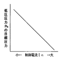
この容量可変装置11bの電磁式圧力制御装置は、圧縮機11の吐出圧と吸入圧を利用して制御圧力(斜板室圧力)を変化させるものであり、図2に示す制御電流Inにより電磁力が調節される電磁機構、およびこの電磁機構の電磁力と吸入圧との釣り合いによって変位する弁体を有し、この弁体により圧縮機1の吐出圧を斜板室内に導く通路の圧損を調節して、制御圧力を変化させるようになっている。
【0025】
容量可変装置11bの電磁式圧力制御装置への通電は後述の図4の空調制御装置40の出力により制御され、例えば、容量可変装置11bの制御電流Inを増大させると、圧縮機吐出容量が増大方向に変化するようになっている。つまり、容量可変装置11bの制御電流Inは、直接的には冷凍サイクルの低圧圧力(吸入圧)Psの目標圧力を決めるものであり、制御電流Inの増加に反比例して低圧圧力Psの目標圧力が図2のように低下するので、制御電流Inの増加により圧縮機吐出容量が増大方向に変化する。
【0026】
従って、制御電流Inの増減により圧縮機11の吐出容量、ひいては吐出冷媒流量が増減して実際の低圧圧力Psを上下させて、蒸発器9の温度(蒸発器吹出温度)が所定の目標温度(低圧圧力Psの目標圧力に対応した温度)となるように蒸発器9の冷却能力を制御できる。ここで、制御電流Inは具体的にはデューティ制御により可変するが、制御電流Inの値をデューティ制御によらず直接連続的に増減してもよい。
【0027】
冷凍サイクル10においては、圧縮機11により冷媒が高温高圧に圧縮され、この圧縮機11から吐出された高圧ガス冷媒は凝縮器(放熱器)12に導入され、この凝縮器12にてガス冷媒は図示しない冷却ファンにより送風される外気と熱交換して放熱し凝縮する。凝縮器12を通過した冷媒を受液器13にて液相冷媒と気相冷媒とに分離するとともに、液相冷媒を受液器13内に貯留する。
【0028】
受液器13からの高圧液冷媒を温度式膨張弁14にて低圧の気液2相状態に減圧し、この減圧後の低圧冷媒を上記の蒸発器9において空調空気から吸熱して蒸発させるようになっている。温度式膨張弁14は周知のごとく蒸発器9出口の冷媒過熱度が所定値に維持されるように弁開度を自動調節するものである。
【0029】
蒸発器9において蒸発した後のガス冷媒は再度、圧縮機11に吸入され、圧縮される。なお、冷凍サイクル10のうち、圧縮機11、凝縮器12、受液器13等の機器は、車両エンジンルーム(図示せず)内に配置されている。
【0030】
一方、空調ユニット1において、蒸発器9の下流側にはケース2内を流れる空気を加熱するヒータコア15を配置している。このヒータコア15は車両エンジンの温水(エンジン冷却水)を熱源として、蒸発器9通過後の空気(冷風)を加熱する暖房用熱交換器であり、その側方にはヒータコア15をバイパスして空気が流れるバイパス通路16が形成してある。
【0031】
蒸発器9とヒータコア15との間にエアミックスドア17を回転自在に配置してある。このエアミックスドア17はサーボモータ18により駆動されて、その回転位置(開度)が連続的に調節可能になっている。エアミックスドア17の開度によりヒータコア15を通る空気量(温風量)と、バイパス通路16を通過してヒータコア15をバイパスする空気量(冷風量)とを調節し、これにより、車室内に吹き出す空気の温度を調節するようになっている。
【0032】
ケース2の空気通路の最下流部には、車両の前面窓ガラスWに向けて空調風を吹き出すためのデフロスタ吹出口19、乗員の顔部に向けて空調風を吹き出すためのフェイス吹出口20、および乗員の足元部に向けて空調風を吹き出すためのフット吹出口21の計3種類の吹出口が設けられている。
【0033】
これら吹出口19〜21の上流部にはデフロスタドア22、フェイスドア23およびフットドア24が回転自在に配置されている。これらのドア22〜24は、図示しないリンク機構を介して共通のサーボモータ25によって駆動される。
【0034】
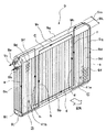
次に、図3により本実施形態における蒸発器9の冷媒流路構成および蒸発器温度センサの具体的配置形態を説明する。蒸発器9はその左右の側面部の一方(図示左側)の上方部に冷媒出入口ジョイント9aを一体に接合し、この冷媒出入口ジョイント9aに、膨張弁14にて減圧された低圧冷媒が流入する冷媒入口9bと蒸発器9にて蒸発したガス冷媒が圧縮機11吸入側へ向かって流出する冷媒出口9cが設けてある。
【0035】
蒸発器9は、多数の偏平チューブ9d相互間にコルゲートフィン9fを一体に接合し、この偏平チューブ9dとコルゲートフィン9fとにより冷媒と送風空気との間で熱交換を行う熱交換コア部を構成している。この熱交換コア部の上下両端部に偏平チューブ9d内の冷媒流路への冷媒分配あるいは偏平チューブ9d内の冷媒流路からの冷媒集合を行うタンク部9g〜9jを構成している。このタンク部9g〜9jは図示の例では偏平チューブ9dと一体成形しているが、タンク部9g〜9jを偏平チューブ9dと別体で成形し、タンク部9g〜9jを偏平チューブ9dと一体に接合(ろう付け)してもよい。
【0036】
タンク部9g〜9jのうちタンク部9g、9iは蒸発器9への空気流れ方向Aの上流側に位置する風上側タンク部であり、これに対し、タンク部9h、9jは蒸発器9への空気流れ方向Aの下流側に位置する風下側タンク部である。
【0037】
上側の両タンク部9g、9h相互間の冷媒流路、および下側の両タンク部9i、9j相互間の冷媒流路はそれぞれ空気流れ方向Aの風上側と風下側とで仕切られている。これに伴って、偏平チューブ9d内の冷媒流路も空気流れ方向Aの風上側と風下側とで仕切られている。
【0038】
このように偏平チューブ9d内の冷媒流路および上下のタンク部9g〜9j内の冷媒流路を空気流れ方向Aの前後で仕切ることにより、蒸発器9の風下側部位に、冷媒入口9bからの冷媒が流れる入口側冷媒流路部9kを形成し、蒸発器9の風上側部位に、入口側冷媒流路部9kからの冷媒が冷媒出口9cに向かって流れる出口側冷媒流路部9mを形成している。従って、冷媒入口9bからの冷媒が最初に蒸発器9の風下側に流れ、その後、蒸発器9の風上側に流れるという対向流型の前後Uターン流路を形成する。
【0039】
冷媒入口9bからの冷媒は蒸発器9の左側面部流路9nを矢印aのように通過(降下)して、入口側冷媒流路部9kの下側タンク9jに流入する。この下側タンク9jの左右方向の中央部には仕切り板9pが配置されているので、冷媒はその後、入口側冷媒流路部9kを矢印b、c、dのように蛇行状に流れて、入口側冷媒流路部9kの出口部(右側下端部)に到達する。
【0040】
この右側下端部の冷媒は蒸発器9の右側面部流路9qを矢印eのように通過(上昇)して、出口側冷媒流路部9mの上側タンク9gの右側上端部に流入する。この上側タンク9gの左右方向の中央部には仕切り板9rが配置されているので、冷媒はその後、出口側冷媒流路部9mを矢印f、g、hのように蛇行状に流れて冷媒出口9cに到達する。
【0041】
図3に示す本実施形態における蒸発器9の冷媒流路構成であると、風下側の入口側冷媒流路部9kでは蒸発器9の左側から右側へと冷媒が流れ、これに対し、風上側の出口側冷媒流路部9mでは蒸発器9の右側から左側へと逆方向に冷媒が流れる。そして、蒸発器9の左側部では入口側冷媒流路部9kと出口側冷媒流路部9mの冷媒流れ方向がともに矢印b、hに示す上昇流となり、蒸発器9の右側部では入口側冷媒流路部9kと出口側冷媒流路部9mの冷媒流れ方向がともに矢印d、fに示す下降流となる。
【0042】
このように、風下側の入口側冷媒流路部9kと風上側の出口側冷媒流路部9mとで、冷媒流れ方向が左右逆転しているとともに、蒸発器9の空気流れ方向Aの前後において重合する冷媒流路部分(矢印b、h部分および矢印d、f部分)では冷媒流れ方向が一致している。
【0043】
これにより、蒸発器9の空気流れ方向Aの前後において重合する冷媒流路部分では、液相冷媒の分布の偏りを相殺して、蒸発器9の吹出空気温度のバラツキを抑制している。
【0044】
ところで、本発明者らの実験検討によると、圧縮機11の吐出容量が大きくてサイクル内循環冷媒流量が大きい場合には、蒸発器9の上記した冷媒流路構成によって蒸発器9の吹出空気温度のバラツキを十分小さい範囲に低減できるが、外気温が低くなる春秋の中間期のように冷房熱負荷が小さい場合には、圧縮機11の吐出容量が減少してサイクル内循環冷媒流量が減少する。
【0045】
このように、サイクル内循環冷媒流量が所定値以下に減少する冷媒小流量時には、蒸発器9の入口側冷媒流路部9kを冷媒が左側から右側へと通過していくにつれて液相冷媒の蒸発が進行し、入口側冷媒流路部9kの出口部である右側下方部位に到達する以前に液相冷媒の蒸発がほぼ終了してしまう場合が生じる。
【0046】
このように入口側冷媒流路部9kの出口部以前に液相冷媒の蒸発が終了すると、風上側の出口側冷媒流路部9mでは過熱ガス冷媒が通過するので、過熱ガス冷媒の顕熱分を送風空気から吸熱するだけとなる。このため、風上側の出口側冷媒流路部9mでは、液相冷媒の蒸発潜熱を送風空気から吸熱できないので、冷却性能が大きく低下する。
【0047】
この結果、冷媒小流量時における蒸発器9の吹出空気温度は、入口側冷媒流路部9kの出口部に相当する右側下方部位▲1▼が最も高温の部位となり、入口側冷媒流路部9kの入口部に相当する左側下方部位▲2▼が最も低温の部位となる。
【0048】
そこで、本実施形態では、蒸発器9の熱交換コア部の空気吹出側(風下側)において冷媒小流量時に高温側領域となる右側下方部位▲1▼に第1蒸発器温度センサ41aを配置し、この高温側領域▲1▼における蒸発器吹出空気温度Te1を検出する。また、蒸発器9の熱交換コア部の空気吹出側(風下側)において冷媒小流量時に低温側領域となる左側下方部位▲2▼に第2蒸発器温度センサ41bを配置し、この低温側領域▲2▼における蒸発器吹出空気温度Te2を検出する。
【0049】
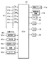
次に、図4により本実施形態の電気制御部の概要を説明すると、空調制御装置40はCPU、ROMおよびRAM等を含んで構成される周知のマイクロコンピュータとその周辺回路から構成されるもので、ROM内に空調制御のための制御プログラムを記憶しており、その制御プログラムに基づいて各種演算、処理を行う。空調制御装置40の入力側にはセンサ群41からのセンサ検出信号、空調パネル42からの操作信号が入力される。
【0050】
センサ群41には、上記した第1、第2蒸発器温度センサ41a、41bが備えられている。この両温度センサ41a、41bにより検出される蒸発器吹出空気温度Te1、Te2に応じて圧縮機11の吐出容量を可変制御し、これにより、蒸発器9の冷却能力を制御するようになっている。この第1、第2蒸発器温度センサ41a、41bの他に、外気温Tam、内気温Tr、日射量Ts、温水温度Tw等を検出する各種のセンサ41c〜41f等が備えられている。
【0051】
空調パネル42は、車室内の運転席前方の計器盤(図示せず)付近に配置されるものであって、乗員により操作される以下の操作スイッチ42a〜42eを有する。温度設定スイッチ42aは車室内の設定温度Tsetの信号を出すものであり、内外気切替スイッチ42bは内外気切替ドア6による内気モードと外気モードをマニュアル設定する信号を出すものである。
【0052】
吹出モードスイッチ42cは吹出モードとして周知のフェイスモード、バイレベルモード、フットモード、フットデフロスタモード、およびデフロスタモードをマニュアル設定するための信号を出すものである。風量切替スイッチ42dは送風機8のオンオフおよび送風機8の風量切替をマニュアル設定するための信号を出すものであり、エアコンスイッチ42eは電磁クラッチ11aの通電のオンオフ信号を出して圧縮機11の作動を断続するものである。
【0053】
空調制御装置40の出力側には、圧縮機11の電磁クラッチ11a、容量可変装置11b、送風機8の駆動用モータ8bおよび各機器の電気駆動手段をなすサーボモータ7、18、25等が接続され、これらの機器の作動が空調制御装置40の出力信号により制御される。
【0054】
次に、上記構成において本実施形態の作動を説明する。最初に、車両用空調置としての作動の概要を説明すると、空調パネル42の風量切替スイッチ42dを投入して送風機8を作動させることにより、空調ユニット1内の通風路に空気が送風される。
【0055】
そして、空調パネル42の圧縮機作動スイッチであるエアコンスイッチ42eを投入すると、空調制御装置40により電磁クラッチ11aに通電されて電磁クラッチ11aが接続状態となり、圧縮機11が車両エンジンにより回転駆動される。また、空調制御装置40により圧縮機11の容量可変装置11bの制御電流Inが後述の図5の制御フローチャートにより決定され、圧縮機11が所定の吐出容量の状態にて作動する。これにより、冷凍サイクル10において蒸発器9に冷媒が循環するので、送風空気を蒸発器9により冷却、除湿して、車室内へ空調風を吹き出すことができる。
【0056】
次に、圧縮機11の容量制御を図5により説明すると、図5は空調制御装置40により実行される制御ルーチンであり、ステップS100にてセンサ群41の検出信号、空調パネル42からの操作信号等を読み込む。次に、ステップ110にて空調ユニット1から車室内へ吹き出す空気の目標吹出温度TAOを算出する。この目標吹出温度TAOは空調熱負荷変動にかかわらず、車室内を設定温度Tsetに維持するために必要な車室内への吹出空気温度であって、TAOは周知のごとく温度設定スイッチ42aにより設定した設定温度Tset、およびセンサ41c〜41eにより検出される外気温Tam、内気温Tr、日射量Tsに基づいて算出する。
【0057】
次に、ステップS120にて蒸発器9の目標蒸発器温度TEOを算出する。この目標蒸発器温度TEOは蒸発器9の吹出空気の目標温度であり、上記TAO、外気温Tam等に基づいて次の数式1のごとく決定される。
【0058】
【数1】
TEO=MIN{f1(Tam),f2(TAO)}
すなわち、第1目標蒸発器温度f1(Tam)および第2目標蒸発器温度f2(TAO)のうち、低い方の温度が目標蒸発器温度TEOとして決定される。
【0059】
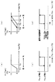
ここで、第1目標蒸発器温度f1(Tam)は、図6(a)に示すように外気温Tamに応じて決定される。具体的には、外気温Tamが所定の第1中間温度T1(例えば、8℃付近)より上昇すると、第1目標蒸発器温度f1(Tam)を最低温度(例えば、3℃)から次第に上昇させ、外気温Tamが所定の第2中間温度T2(例えば、17℃付近)まで上昇すると、第1目標蒸発器温度f1(Tam)が最高温度(例えば、11℃)となる。これにより、中間温度域における圧縮機動力の低減を図ることができる。
【0060】
なお、外気温Tamが第1中間温度T1より低い低外気温時に第1目標蒸発器温度f1(Tam)を最低温度(例えば、3℃)にしている理由は、低外気温時における窓ガラス防曇のための蒸発器除湿能力を確保するためである。
【0061】
また、第2目標蒸発器温度f2(TAO)は図6(b)に示すように目標吹出温度TAOの上昇に応じて上昇するように決定される。具体的には、目標吹出温度TAOが第1所定温度T3(例えば、7℃付近)より上昇すると、第2目標蒸発器温度f2(TAO)を最低温度(例えば、3℃)から次第に上昇させ、目標吹出温度TAOが第2所定温度T4(例えば、20℃付近)まで上昇すると、第2目標蒸発器温度f2(TAO)が最高温度(例えば、11℃)となる。
【0062】
なお、所定温度T3’、t4’はそれぞれ第1、第2所定温度T3、T4より所定温度低い温度であり、制御のハンチング防止のためのヒステリシス幅を設定するためのものである。
【0063】
次に、ステップS130にて高温側領域▲1▼の蒸発器吹出温度Te1と低温側領域▲2▼の蒸発器吹出温度Te2のいずれが高いか判定する。ここで、Te1とTe2の高低を判定するのは次の理由からである。すなわち、冷媒小流量時には、前述のように高温側領域▲1▼の蒸発器吹出温度Te1が低温側領域▲2▼の蒸発器吹出温度Te2よりも常に高くなる。しかし、冷媒大流量時には、蒸発器9の風下側の入口側冷媒流路部9kを通過した後に風上側の出口側冷媒流路部9mに流入する冷媒中にも液相冷媒が残存し、出口側冷媒流路部9mでも液相冷媒の蒸発が継続される。従って、冷媒大流量時にはTe1の方がTe2より低くなる場合が起こり得る。
【0064】
そこで、ステップS130にてTe1とTe2の高低を判定するのである。この判定は、具体的には、図6(c)に示すように、Te1とTe2の差(Te1−Te2)に対して容量制御のハンチング防止のヒステリシス幅を持つように設定してある。図6(c)のヒステリシス幅Aは例えば、1℃程度の値である。
【0065】
冷媒小流量時には、高温側領域▲1▼の蒸発器吹出温度Te1が低温側領域▲2▼の蒸発器吹出温度Te2よりも高いので、テップS140に進む。冷媒大流量時において、低温側領域▲2▼の蒸発器吹出温度Te2が高温側領域▲1▼の蒸発器吹出温度Te1より高い状態が発生したときはステップS150に進む。
【0066】
高温側領域▲1▼の蒸発器吹出温度Te1が低温側領域▲2▼の蒸発器吹出温度Te2より高いときはステップS140にて、高温側領域▲1▼の蒸発器吹出温度Te1に基づく通常の圧縮機容量制御を行う。具体的には、圧縮機11の容量可変装置11bに出力する制御電流Inを高温側領域▲1▼の蒸発器吹出温度Te1に基づいて算出し、この制御電流Inにより圧縮機11の容量を可変制御する。
【0067】
この制御電流Inは前述の図2に示すように圧縮機11の容量可変装置11bにおける電磁式圧力制御装置の目標低圧圧力を決定するものであって、制御電流Inは、第1蒸発器温度センサ41aにより検出される実際の高温側領域▲1▼の蒸発器吹出温度Te1が上記目標蒸発器温度TEOとなるように決定される。
【0068】
この制御電流値Inの具体的算出方法としては、まず、実際の蒸発器吹出温度Te1と目標蒸発器温度TEOとの偏差En(En=Te1−TEO)を算出し、この偏差Enに基づいて制御電流値Inを比例積分制御(PI制御)等によるフィードバック制御の手法にて算出すればよい。
【0069】
また、ステップS140では、高温側領域▲1▼の蒸発器吹出温度Te1に比較して低い温度である低温側領域▲2▼の蒸発器吹出温度Te2に基いてフロスト防止容量制御を行う。ここで、フロスト防止容量制御とは、蒸発器9で発生する凝縮水がフロスト(凍結)することを防止するための容量制御である。
【0070】
具体的には、図6(d)に示すように、高温側領域▲1▼の蒸発器吹出温度Te1および低温側領域▲2▼の蒸発器吹出温度Te2のうち、低い方の温度(ステップS140では低温側領域▲2▼の蒸発器吹出温度Te2)が所定のフロスト判定温度−B℃(例えば−4℃)まで低下すると、制御電流値Inを強制的に最小値にして、圧縮機容量を強制的に略0%容量に引き下げる。
【0071】
これにより、冷凍サイクル10内の冷媒循環がほとんど無くなり、蒸発器9での冷媒蒸発による冷却作用がほとんど無くなる。そのため、蒸発器9のフロストが広範囲にわたって進行することを防止して、フロストによる蒸発器9の冷却性能の低下を未然に防止できる。
【0072】
なお、図6(d)において通常の容量制御とは、上述したように実際の蒸発器吹出温度Te1、またはTe2が目標蒸発器温度TEOとなるように圧縮機容量を可変制御する制御のことを言う。
【0073】
一方、冷媒大流量時において低温側領域▲2▼の蒸発器吹出温度Te2が高温側領域▲1▼の蒸発器吹出温度Te1より高い状態が発生したときはステップS140からステップS150に進み、低温側領域▲2▼の蒸発器吹出温度Te2に基づく通常の圧縮機容量制御を行う。
【0074】
具体的には、圧縮機11の容量可変装置11bに出力する制御電流Inを低温側領域▲2▼の蒸発器吹出温度Te2に基づいて算出し、この制御電流Inにより圧縮機11の容量を可変制御する。
【0075】
また、ステップS150では、低温側領域▲2▼の蒸発器吹出温度Te2に比較して低い温度である高温側領域▲1▼の蒸発器吹出温度Te1に基いてフロスト防止容量制御を行う。このフロスト防止容量制御もステップS140における上述のフロスト防止容量制御(図6(d)に示す制御)と同じであり、高温側領域▲1▼の蒸発器吹出温度Te1が所定のフロスト判定温度−B℃(例えば−4℃)まで低下すると、制御電流値Inを強制的に最小値にして、圧縮機容量を強制的に略0%容量に引き下げる。
【0076】
次に、第1実施形態による作用効果を説明する。外気温Tamの中間温度域(例えば、20℃付近)では、冷房熱負荷が小さくなるので、車室内吹出空気の目標吹出温度TAOは夏期に比較して高めの温度となる。そのため、図6(b)に示す目標吹出温度TAOに基づいて決定される第2目標蒸発器温度f2(TAO)も最高温度の11℃付近となる。
【0077】
そして、外気温Tamの中間温度域では図6(a)に示す特性に従って第1目標蒸発器温度f1(Tam)も最高温度の11℃付近となる。これにより、目標蒸発器温度TEOが最高温度の11℃付近となるので、外気温Tamの中間温度域では実際の蒸発器吹出温度Te1、Te2がこの最高温度の11℃付近となるように圧縮機11の容量制御が行われる。従って、圧縮機11の容量が小容量側に移行するので、圧縮機11の駆動動力を低減でき、省動力(エコノミー)制御を実行できる。
【0078】
ところで、この省動力制御時には、圧縮機11の容量が小容量側に移行してサイクル内循環冷媒流量が減少するので、前述の理由から蒸発器9の空気吹出側のうち入口側冷媒流路部9kの入口付近(図3の左側下方部付近)に低温側領域▲2▼が発生し、入口側冷媒流路部9kの出口付近(図3の右側下方部付近)に高温側領域▲1▼が発生する。
【0079】
しかし、第1実施形態によると、高温側領域▲1▼と低温側領域▲2▼における蒸発器吹出温度Te1、Te2を比較して、高温側領域▲1▼の蒸発器吹出温度Te1が低温側領域▲2▼の蒸発器吹出温度Te2より高いときは、ステップS140にて高温側領域▲1▼の蒸発器吹出温度Te1が目標蒸発器温度TEOとなるように、圧縮機11の容量制御を行うから、高温側領域▲1▼の蒸発器吹出温度Te1を確実に目標蒸発器温度TEOに制御できる。
【0080】
従って、冷媒小流量時(省動力制御時)においても、蒸発器高温側領域▲1▼の吹出空気温度Te1が蒸発器低温側領域▲2▼の蒸発器吹出温度Te2より大幅に上昇するという不具合を解消できる。これにより、車室内吹出空気温度のバラツキを低減して、温度バラツキによる空調フィーリングの悪化を回避できる。
【0081】
一方、蒸発器9のフロスト防止制御については、高温側領域▲1▼と低温側領域▲2▼における蒸発器吹出温度Te1、Te2を比較して、低い温度の方の蒸発器吹出温度が所定のフロスト判定温度−B℃(例えば、−4℃)まで低下すると、圧縮機11の容量を強制的に略0%容量に引き下げるから、蒸発器9のフロストの進行を確実に防止できる。
【0082】
なお、本第1実施形態において、フロスト判定温度を−4℃という氷点下の温度に設定しているのは、冬期の低外気温時に蒸発器9の除湿作用による窓ガラスの防曇性能を確保するためである。そして、冬期の低外気温時には、蒸発器9の熱負荷が小さいため、圧縮機容量が小さくなって、サイクル内循環冷媒流量が小さくなっているとともに、外気の絶対湿度が低くなって、凝縮水発生量が小さくなっているので、フロスト判定温度を氷点下の−4℃に設定しても、蒸発器9のフロスト防止の観点から支障はない。
【0083】
(第2実施形態)
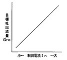
第1実施形態では、外部可変容量型圧縮機11として、容量可変装置11bの制御電流Inにより図2のように低圧圧力Psの目標圧力を設定して、低圧圧力Psがこの目標圧力に維持されるように吐出容量を増減させるもの(低圧圧力制御式)を用いているが、第2実施形態では、外部可変容量型圧縮機11として、容量可変装置11bの制御電流Inにより図7のように圧縮機吐出流量の目標流量Groを設定して、圧縮機吐出流量が目標吐出流量Groに維持されるように吐出容量を増減させるもの(吐出流量制御式)を用いる。
【0084】
より具体的に説明すると、第2実施形態による吐出流量制御式の外部可変容量型圧縮機11においては、その吐出側に絞り部を設けており、この絞り部前後に発生する差圧は吐出流量と比例関係にある。従って、この絞り部前後の差圧が目標差圧となるように吐出容量を増減させれば、圧縮機吐出流量が目標吐出流量Groに維持される。
【0085】
そこで、容量可変装置11bに、制御電流Inにより電磁力が決定される電磁機構を設け、この電磁機構により上記目標差圧に相当する電磁力を決定し、この目標差圧に相当する電磁力と絞り部前後の差圧による力との釣り合いにより弁開度を増減する弁機構を容量可変装置11bに備える。
【0086】
この弁機構の弁開度の増減により斜板室の圧力を制御することにより、斜板の傾斜角度を可変して圧縮機吐出容量を略0%〜100%の範囲で連続的に変化させることができる。このような吐出流量制御式の外部可変容量型圧縮機11を用いても第1実施形態と同様の作用効果を発揮できる。なお、吐出流量制御式の外部可変容量型圧縮機11は特開2001−107854号公報等により公知である。
【0087】
(第3実施形態)
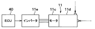
第1、第2実施形態では、いずれも、圧縮機として吐出容量を変更可能な外部可変容量型圧縮機11を用い、吐出容量の変更により吐出流量を変更する場合について説明したが、第3実施形態では図8に示すように圧縮機として電動圧縮機11を用いている。この電動圧縮機11は、モータ11cとこのモータ11cにより駆動される圧縮機構部11dとを一体化したものである。モータ11cは具体的には3相交流モータであり、また、圧縮機構部11dは周知のスクロール式圧縮機構である。
【0088】
モータ11cに付与される3相交流電源の周波数をインバータ11eにより可変制御することによりモータ回転数を制御し、モータ回転数の高低に応じて電動圧縮機11の冷媒吐出流量を増減できる。インバータ11eは空調用制御装置40の制御出力により制御される。
【0089】
第3実施形態によると、高温側領域▲1▼と低温側領域▲2▼における蒸発器吹出温度Te1、Te2を比較して、高い方の蒸発器吹出温度が目標蒸発器温度TEOとなるように、電動圧縮機11の回転数(すなわち、電動圧縮機11の冷媒吐出流量)を制御することにより、冷媒小流量時にも高温側領域▲1▼の蒸発器吹出温度Te1を確実に目標蒸発器温度TEOに制御できる。
【0090】
従って、冷媒小流量時(省動力制御時)においても、蒸発器高温側領域▲1▼の吹出空気温度Te1が蒸発器低温側領域▲2▼の蒸発器吹出温度Te2より大幅に上昇するという不具合を解消できる。
【0091】
また、高温側領域▲1▼と低温側領域▲2▼における蒸発器吹出温度Te1、Te2のうち、低い方の蒸発器吹出温度が所定のフロスト判定温度(例えば、−4℃)まで低下したときときは、モータ11cへの電源供給を遮断して電動圧縮機11を停止する。これにより、蒸発器9のフロスト進行を確実に防止できる。
【0092】
このように、圧縮機として外部可変容量型圧縮機11の代わりに電動圧縮機11を用いても、第1、第2実施形態と同様の作用効果を発揮できる。
【0093】
(他の実施形態)
なお、第1実施形態では、可変容量型圧縮機11に電磁クラッチ11aを備えて、電磁クラッチ11aへの通電を断続して圧縮機11の運転を断続するようにしているが、可変容量型圧縮機11はその吐出容量を略0%付近まで減少させるものであるから、電磁クラッチ11aを廃止して、車両エンジンの運転時にはプーリ、ベルト等を介して常時、エンジンの回転動力が可変容量型圧縮機11に伝達されるようにしてもよい。この場合は、空調パネル42のエアコンスイッチ42eがオフになっているときは可変容量型圧縮機11の吐出容量を略0%付近の最小容量に維持して、可変容量型圧縮機11を実質的な停止状態とする。
【0094】
また、第1実施形態では、蒸発器9の空気吹出側において高温側領域▲1▼および低温側領域▲2▼にそれぞれ吹出空気温度Te1、Te2を検出する吹出温度センサ41a、41bを配置し、この吹出温度センサ41a、41bを第1、第2蒸発器温度検出手段として用いているが、第1、第2蒸発器温度検出手段として、空気吹出側のフィン表面温度等を検出する温度検出手段を用いてもよい。
【図面の簡単な説明】
【図1】本発明の第1実施形態を示す車両用空調装置の概要システム構成図である。
【図2】第1実施形態に用いる可変容量型圧縮機の制御特性図である。
【図3】第1実施形態に用いる蒸発器の斜視図である。
【図4】第1実施形態における電気制御部の概略ブロック図である。
【図5】第1実施形態による可変容量型圧縮機の容量制御のフローチャートである。
【図6】図4のフローチャートの作動説明に供する各種制御特性図である。
【図7】第2実施形態による可変容量型圧縮機の制御特性図である。
【図8】第3実施形態による電動圧縮機の制御ブロック図である。
【符号の説明】
1…空調ユニット、8…送風機、9…蒸発器、10…冷凍サイクル、
11…圧縮機、40…空調用制御装置(制御手段)、
41a…蒸発器高温側領域の温度センサ(第1蒸発器温度検出手段)、
41b…蒸発器低温側領域の温度センサ(第2蒸発器温度検出手段)。[0001]
TECHNICAL FIELD OF THE INVENTION
The present invention relates to a refrigeration cycle device including a compressor such as a variable displacement compressor or an electric compressor, which has a configuration capable of controlling a discharge refrigerant flow rate by an external control signal, and is used for a vehicle air conditioner. It is suitable.
[0002]
[Prior art]
2. Description of the Related Art Conventionally, in a vehicle air conditioner, a compressor of a refrigeration cycle device is driven by a vehicle engine, so that the operation of a fixed displacement compressor is intermittently operated by an electromagnetic clutch to perform the capacity of the compressor. However, shocks and noises are generated due to the intermittent control of the compressor operation, which deteriorates the running feeling of the vehicle.
[0003]
Therefore, in recent years, a variable displacement compressor capable of controlling the discharge capacity by an external control signal has been adopted. In this variable displacement compressor, the displacement can be continuously and finely changed, so that the running feeling of the vehicle can be improved.
[0004]
More specifically, the control of the discharge capacity is calculated by calculating a deviation between the actual outlet temperature Te of the evaporator provided in the refrigeration cycle device and the target evaporator temperature TEO, and controlling the displacement of the compressor based on the deviation. The current is calculated, and the displacement control current is output to a displacement varying device of the compressor to control the displacement of the compressor. Thus, the flow rate of the refrigerant to the evaporator is increased or decreased to increase or decrease the evaporator cooling capacity, so that the evaporator outlet temperature Te is maintained near the target evaporator temperature TEO.
[0005]
[Problems to be solved by the invention]
By the way, when the cooling heat load is low as in the middle of spring and autumn, the evaporator suction air temperature becomes low. In addition, the target evaporator temperature TEO is changed to a temperature higher than at the time of high cooling load in order to save compressor driving power. As a result, the required cooling capacity of the evaporator is reduced, so that the discharge capacity of the compressor is controlled to a small capacity, and the evaporator circulating refrigerant flow rate is reduced.
[0006]
At such a small flow rate of the refrigerant, the distribution of the liquid refrigerant in the refrigerant flow path between the refrigerant inlet and the refrigerant outlet of the evaporator is likely to be uneven, which causes a problem that the temperature of the air blown out from the evaporator increases. .
[0007]
According to the study by the present inventors, in a refrigeration cycle device using an electric compressor capable of controlling the discharge refrigerant flow rate by controlling the rotation speed instead of the variable displacement compressor as the compressor, even when the refrigerant has a small flow rate, It has been confirmed that the problem that the variation in the temperature of the air blown from the evaporator becomes large similarly occurs.
[0008]
In view of the above, the present invention relates to a refrigeration cycle apparatus including a compressor, such as a variable displacement compressor or an electric compressor, having a configuration in which the discharged refrigerant flow rate can be controlled by an external control signal. It is an object of the present invention to reduce the variation of the evaporator blow-out air temperature at the time of flow rate.
[0009]
[Means for Solving the Problems]
In order to achieve the above object, according to the first aspect of the present invention, a compressor (11) configured to be able to control a discharge refrigerant flow rate by an external control signal and a suction side of the compressor (11) are provided. An evaporator (9) connected to evaporate the low-pressure refrigerant, and a first evaporator temperature disposed in a high-temperature side region of the air outlet side of the evaporator (9) where the evaporator temperature becomes high when the refrigerant has a small flow rate. Detecting means (41a); second evaporator temperature detecting means (41b) disposed in a low-temperature side region of the air blowing side of the evaporator (9) where the evaporator temperature becomes low at a small refrigerant flow; Control means (40) for receiving detection signals from the first evaporator temperature detecting means (41a) and the second evaporator temperature detecting means (41b) and controlling the flow rate of refrigerant discharged from the compressor (11);
Based on the higher evaporator temperature and the target evaporator temperature among the evaporator temperatures detected by the first evaporator temperature detecting means (41a) and the second evaporator temperature detecting means (41b), the compressor ( 11) The method is characterized in that the flow rate of the discharged refrigerant is controlled.
[0010]
According to this, even when unevenness of the evaporator temperature occurs due to uneven distribution of the liquid refrigerant in the evaporator refrigerant flow path at the time of the small flow rate of the refrigerant, the evaporator temperature of the high temperature side region and the low temperature side region of this temperature fluctuation In addition, the flow rate of the refrigerant discharged from the compressor (11) can be controlled such that the evaporator temperature in the high temperature side region becomes the target evaporator temperature.
[0011]
Therefore, the evaporator temperature in the high-temperature side region is prevented from greatly increasing at the small flow rate of the refrigerant as compared with the low-temperature side region, and the deterioration of the air conditioning feeling due to the increase in the variation of the evaporator blown air temperature can be suppressed.
[0012]
According to a second aspect of the present invention, in the first aspect, the lower evaporator of the evaporator temperatures detected by the first evaporator temperature detecting means (41a) and the second evaporator temperature detecting means (41b). When the temperature decreases to a predetermined frost determination temperature, the compressor (11) is controlled so that the discharged refrigerant flow rate becomes substantially zero.
[0013]
Thereby, the frost progress of the evaporator (9) can be reliably prevented.
[0014]
As in the third aspect of the invention, in the first or second aspect, the target evaporator temperature can be specifically determined based on at least the target blow-out temperature of the air blown into the room and the outside air temperature.
[0015]
As in the fourth aspect of the present invention, in any one of the first to third aspects, the compressor (11) can be specifically configured by a variable displacement type compressor capable of changing a discharge capacity, By changing the discharge capacity, the discharge refrigerant flow rate can be changed.
[0016]
According to the fifth aspect of the present invention, in any one of the first to third aspects, specifically, an electric compressor driven by a motor (11c) may be used as the compressor (11). The flow rate of the discharged refrigerant can be changed by controlling the rotation speed of the motor (11c).
[0017]
In addition, the code | symbol in the parenthesis of each said means shows the correspondence with the concrete means described in embodiment mentioned later.
[0018]
BEST MODE FOR CARRYING OUT THE INVENTION
(1st Embodiment)
FIG. 1 shows an outline of the overall configuration of the first embodiment. The vehicle air conditioner includes an air conditioning unit 1 disposed inside an instrument panel (not shown) at the forefront of the vehicle compartment. The air conditioning unit 1 has a
[0019]
The inside / outside air switching door 6 is driven by a
[0020]
On the downstream side of the inside / outside air switching box 5, an
[0021]
The refrigerating
[0022]
The
[0023]
The external
[0024]
The electromagnetic pressure control device of the
[0025]
The energization of the
[0026]
Accordingly, the discharge capacity of the
[0027]
In the
[0028]
The high-pressure liquid refrigerant from the
[0029]
The gas refrigerant evaporated in the
[0030]
On the other hand, in the air conditioning unit 1, a
[0031]
An
[0032]
A
[0033]
A
[0034]
Next, the refrigerant flow path configuration of the
[0035]
The
[0036]
Of the
[0037]
The refrigerant flow path between the
[0038]
As described above, the refrigerant flow path in the
[0039]
The refrigerant from the
[0040]
The refrigerant at the lower right end of the right side flows through the right
[0041]
With the refrigerant flow path configuration of the
[0042]
As described above, the refrigerant flow direction is reversed left and right between the leeward-side inlet-side refrigerant
[0043]
Thus, in the refrigerant flow path portion where polymerization occurs before and after in the air flow direction A of the
[0044]
By the way, according to the experimental study of the present inventors, when the discharge capacity of the
[0045]
As described above, at the time of the small flow rate of the refrigerant in which the circulating refrigerant flow rate in the cycle is reduced to the predetermined value or less, as the refrigerant passes from the left side to the right side through the inlet side refrigerant
[0046]
When the evaporation of the liquid-phase refrigerant is completed before the outlet of the inlet-side
[0047]
As a result, the temperature of the air blown out of the
[0048]
Therefore, in the present embodiment, the first
[0049]
Next, an outline of the electric control unit of the present embodiment will be described with reference to FIG. 4. The air
[0050]
The
[0051]
The air-
[0052]
The
[0053]
On the output side of the air-
[0054]
Next, the operation of the present embodiment in the above configuration will be described. First, an outline of the operation of the vehicle air conditioner will be described. When the air volume changeover switch 42d of the
[0055]
Then, when the
[0056]
Next, the capacity control of the
[0057]
Next, in step S120, the target evaporator temperature TEO of the
[0058]
(Equation 1)
TEO = MIN {f1 (Tam), f2 (TAO)}
That is, the lower one of the first target evaporator temperature f1 (Tam) and the second target evaporator temperature f2 (TAO) is determined as the target evaporator temperature TEO.
[0059]
Here, the first target evaporator temperature f1 (Tam) is determined according to the outside air temperature Tam as shown in FIG. Specifically, when the outside air temperature Tam rises from a predetermined first intermediate temperature T1 (for example, around 8 ° C.), the first target evaporator temperature f1 (Tam) is gradually raised from the lowest temperature (for example, 3 ° C.). When the outside air temperature Tam rises to a predetermined second intermediate temperature T2 (for example, around 17 ° C.), the first target evaporator temperature f1 (Tam) becomes the highest temperature (for example, 11 ° C.). This makes it possible to reduce the compressor power in the intermediate temperature range.
[0060]
The reason why the first target evaporator temperature f1 (Tam) is set to the lowest temperature (for example, 3 ° C.) when the outside air temperature Tam is lower than the first intermediate temperature T1 is that the window glass protection at the low outside air temperature. This is to secure the evaporator dehumidifying capacity for fogging.
[0061]
Further, the second target evaporator temperature f2 (TAO) is determined so as to increase in accordance with the increase of the target outlet temperature TAO as shown in FIG. Specifically, when the target outlet temperature TAO rises from the first predetermined temperature T3 (for example, around 7 ° C.), the second target evaporator temperature f2 (TAO) is gradually raised from the minimum temperature (for example, 3 ° C.) When the target outlet temperature TAO rises to the second predetermined temperature T4 (for example, around 20 ° C.), the second target evaporator temperature f2 (TAO) becomes the highest temperature (for example, 11 ° C.).
[0062]
The predetermined temperatures T3 'and t4' are lower than the first and second predetermined temperatures T3 and T4 by a predetermined temperature, respectively, and are for setting a hysteresis width for preventing hunting of control.
[0063]
Next, in step S130, it is determined which of the evaporator outlet temperature Te1 in the high temperature side region (1) and the evaporator outlet temperature Te2 in the low temperature side region (2) is higher. Here, the reason why the level of Te1 and Te2 is determined is as follows. That is, at the time of the small flow rate of the refrigerant, as described above, the evaporator outlet temperature Te1 in the high temperature side region (1) is always higher than the evaporator outlet temperature Te2 in the low temperature side region (2). However, at the time of the large flow rate of the refrigerant, the liquid-phase refrigerant remains in the refrigerant flowing into the outlet-side refrigerant
[0064]
Therefore, the level of Te1 and Te2 is determined in step S130. Specifically, as shown in FIG. 6C, this determination is made so that the difference between Te1 and Te2 (Te1-Te2) has a hysteresis width for preventing hunting of the capacity control. The hysteresis width A in FIG. 6C is, for example, a value of about 1 ° C.
[0065]
At the time of the small flow rate of the refrigerant, since the evaporator outlet temperature Te1 in the high temperature side region (1) is higher than the evaporator outlet temperature Te2 in the low temperature side region (2), the process proceeds to Step S140. If the state in which the evaporator outlet temperature Te2 in the low temperature region (2) is higher than the evaporator outlet temperature Te1 in the high temperature region (1) occurs at the time of the large flow rate of the refrigerant, the process proceeds to step S150.
[0066]
When the evaporator outlet temperature Te1 in the high-temperature side region (1) is higher than the evaporator outlet temperature Te2 in the low-temperature side region (2), a normal operation based on the evaporator outlet temperature Te1 in the high-temperature side region (1) is performed in step S140. Perform compressor capacity control. Specifically, the control current In to be output to the
[0067]
The control current In determines the target low pressure of the electromagnetic pressure control device in the
[0068]
As a specific method of calculating the control current value In, first, a deviation En (En = Te1-TEO) between the actual evaporator outlet temperature Te1 and the target evaporator temperature TEO is calculated, and control is performed based on the deviation En. What is necessary is just to calculate the electric current value In by the technique of the feedback control by proportional integral control (PI control) etc.
[0069]
In step S140, frost prevention capacity control is performed based on the evaporator outlet temperature Te2 in the low-temperature side region (2), which is lower than the evaporator outlet temperature Te1 in the high-temperature side region (1). Here, the frost prevention capacity control is capacity control for preventing condensed water generated in the
[0070]
Specifically, as shown in FIG. 6D, the lower one of the evaporator outlet temperature Te1 in the high-temperature side region (1) and the evaporator outlet temperature Te2 in the low-temperature side region (2) (step S140). When the evaporator outlet temperature Te2 in the low temperature side area {circle around (2)} drops to a predetermined frost judgment temperature −B ° C. (for example, −4 ° C.), the control current value In is forcibly reduced to a minimum value to reduce the compressor capacity. The capacity is forcibly reduced to approximately 0%.
[0071]
Thereby, the circulation of the refrigerant in the
[0072]
The normal displacement control in FIG. 6D refers to control for variably controlling the compressor displacement so that the actual evaporator outlet temperature Te1 or Te2 becomes the target evaporator temperature TEO as described above. To tell.
[0073]
On the other hand, when the state in which the evaporator outlet temperature Te2 in the low-temperature side area (2) is higher than the evaporator outlet temperature Te1 in the high-temperature side area (1) occurs at the time of the large flow rate of the refrigerant, the process proceeds from step S140 to step S150. Normal compressor capacity control is performed based on the evaporator outlet temperature Te2 in the area (2).
[0074]
More specifically, the control current In to be output to the
[0075]
In step S150, the frost prevention capacity control is performed based on the evaporator outlet temperature Te1 in the high temperature side region (1) which is lower than the evaporator outlet temperature Te2 in the low temperature side region (2). This frost prevention capacity control is the same as the above-described frost prevention capacity control in step S140 (the control shown in FIG. 6D), and the evaporator blowout temperature Te1 in the high temperature side region {circle around (1)} is a predetermined frost determination temperature −B When the temperature drops to ℃ (for example, −4 ° C.), the control current value In is forcibly reduced to the minimum value, and the compressor capacity is forcibly reduced to approximately 0% capacity.
[0076]
Next, the operation and effect of the first embodiment will be described. In an intermediate temperature range of the outside air temperature Tam (for example, around 20 ° C.), the cooling heat load is small, so that the target outlet temperature TAO of the air blown into the vehicle compartment is higher than in summer. Therefore, the second target evaporator temperature f2 (TAO) determined based on the target outlet temperature TAO shown in FIG.
[0077]
Then, in the intermediate temperature range of the outside air temperature Tam, the first target evaporator temperature f1 (Tam) also becomes close to the maximum temperature of 11 ° C. according to the characteristic shown in FIG. As a result, the target evaporator temperature TEO is close to the maximum temperature of 11 ° C., so that the compressors are set so that the actual evaporator outlet temperatures Te1 and Te2 are close to the maximum temperature of 11 ° C. in the intermediate temperature range of the outside air temperature Tam. Eleven capacity controls are performed. Therefore, since the capacity of the
[0078]
By the way, during the power saving control, the capacity of the
[0079]
However, according to the first embodiment, the evaporator outlet temperatures Te1 and Te2 in the high-temperature region (1) and the low-temperature region (2) are compared, and the evaporator outlet temperature Te1 in the high-temperature region (1) is lower. When the temperature is higher than the evaporator outlet temperature Te2 in the region (2), the capacity of the
[0080]
Therefore, even at the time of the small flow rate of the refrigerant (during the power saving control), the blowout air temperature Te1 in the evaporator high temperature side area (1) rises significantly than the evaporator blowout temperature Te2 in the evaporator low temperature side area (2). Can be eliminated. As a result, it is possible to reduce the variation in the temperature of the air blown out from the vehicle interior, and to avoid the deterioration of the air conditioning feeling due to the temperature variation.
[0081]
On the other hand, regarding the frost prevention control of the
[0082]
In the first embodiment, the frost determination temperature is set to a temperature below the freezing point of −4 ° C. to ensure the anti-fog performance of the window glass by the dehumidifying action of the
[0083]
(2nd Embodiment)
In the first embodiment, as the external
[0084]
More specifically, in the external
[0085]
Therefore, an electromagnetic mechanism whose electromagnetic force is determined by the control current In is provided in the
[0086]
By controlling the pressure of the swash plate chamber by increasing or decreasing the valve opening of the valve mechanism, the inclination angle of the swash plate can be varied to continuously change the compressor discharge capacity in a range of approximately 0% to 100%. it can. The same operation and effect as in the first embodiment can be exerted by using such an external
[0087]
(Third embodiment)
In the first and second embodiments, the case where the external
[0088]
The motor rotation speed is controlled by variably controlling the frequency of the three-phase AC power supplied to the
[0089]
According to the third embodiment, the evaporator outlet temperatures Te1 and Te2 in the high-temperature side region (1) and the low-temperature side region (2) are compared so that the higher evaporator outlet temperature becomes the target evaporator temperature TEO. By controlling the number of revolutions of the electric compressor 11 (that is, the refrigerant discharge flow rate of the electric compressor 11), the evaporator outlet temperature Te1 in the high temperature side region (1) can be reliably set even when the refrigerant is at a small flow rate. It can be controlled to TEO.
[0090]
Therefore, even at the time of the small flow rate of the refrigerant (during the power saving control), the blowout air temperature Te1 in the evaporator high temperature side area (1) rises significantly than the evaporator blowout temperature Te2 in the evaporator low temperature side area (2). Can be eliminated.
[0091]
Further, when the lower one of the evaporator outlet temperatures Te1 and Te2 in the high-temperature side region (1) and the low-temperature side region (2) drops to a predetermined frost judgment temperature (for example, -4 ° C.). At this time, the power supply to the
[0092]
As described above, even when the
[0093]
(Other embodiments)
In the first embodiment, the
[0094]
Further, in the first embodiment, on the air blowing side of the
[Brief description of the drawings]
FIG. 1 is a schematic system configuration diagram of a vehicle air conditioner showing a first embodiment of the present invention.
FIG. 2 is a control characteristic diagram of a variable displacement compressor used in the first embodiment.
FIG. 3 is a perspective view of an evaporator used in the first embodiment.
FIG. 4 is a schematic block diagram of an electric control unit according to the first embodiment.
FIG. 5 is a flowchart of capacity control of the variable displacement compressor according to the first embodiment.
FIG. 6 is a diagram showing various control characteristics used for explaining the operation of the flowchart of FIG. 4;
FIG. 7 is a control characteristic diagram of a variable displacement compressor according to a second embodiment.
FIG. 8 is a control block diagram of an electric compressor according to a third embodiment.
[Explanation of symbols]
1 ... air conditioning unit, 8 ... blower, 9 ... evaporator, 10 ... refrigeration cycle,
11 compressor, 40 air conditioning control device (control means),
41a: temperature sensor (first evaporator temperature detecting means) in the evaporator high temperature side region;
41b: Temperature sensor in the low temperature side of the evaporator (second evaporator temperature detecting means).
Claims (5)
前記圧縮機(11)の吸入側に接続され、低圧冷媒を蒸発させる蒸発器(9)と、
前記蒸発器(9)の空気吹出側のうち、冷媒小流量時に蒸発器温度が高温となる高温側領域に配置された第1蒸発器温度検出手段(41a)と、
前記蒸発器(9)の空気吹出側のうち、冷媒小流量時に蒸発器温度が低温となる低温側領域に配置された第2蒸発器温度検出手段(41b)と、
前記第1蒸発器温度検出手段(41a)および前記第2蒸発器温度検出手段(41b)の検出信号が入力され、前記圧縮機(11)の吐出冷媒流量を制御する制御手段(40)とを備え、
前記第1蒸発器温度検出手段(41a)および前記第2蒸発器温度検出手段(41b)により検出される蒸発器温度のうち、高い方の蒸発器温度と目標蒸発器温度とに基づいて、前記圧縮機(11)の吐出冷媒流量を制御することを特徴とする冷凍サイクル装置。A compressor (11) configured to be able to control the flow rate of the discharged refrigerant by an external control signal;
An evaporator (9) connected to the suction side of the compressor (11) and evaporating the low-pressure refrigerant;
A first evaporator temperature detecting means (41a) disposed in a high temperature side region of the evaporator (9) on the air blowing side where the evaporator temperature becomes high when the refrigerant has a small flow rate;
A second evaporator temperature detecting means (41b) disposed in a low-temperature side region where the evaporator temperature is low when the refrigerant has a small flow rate, on the air blowing side of the evaporator (9);
A detection signal from the first evaporator temperature detection means (41a) and a detection signal from the second evaporator temperature detection means (41b) are inputted, and a control means (40) for controlling a refrigerant flow rate discharged from the compressor (11) is provided. Prepare
Based on the higher one of the evaporator temperatures detected by the first evaporator temperature detecting means (41a) and the second evaporator temperature detecting means (41b) and the target evaporator temperature, A refrigeration cycle apparatus characterized by controlling a flow rate of refrigerant discharged from a compressor (11).
前記目標蒸発器温度は、少なくとも前記室内へ吹き出す空気の目標吹出温度と外気温に基づいて決定されることを特徴とする請求項1または2に記載の冷凍サイクル装置。The air that has passed through the evaporator (9) blows out into the room to be air-conditioned.
The refrigeration cycle apparatus according to claim 1, wherein the target evaporator temperature is determined based on at least a target blow temperature of air blown into the room and an outside air temperature.
Priority Applications (1)
| Application Number | Priority Date | Filing Date | Title |
|---|---|---|---|
| JP2003023940A JP4258217B2 (en) | 2003-01-31 | 2003-01-31 | Refrigeration cycle equipment |
Applications Claiming Priority (1)
| Application Number | Priority Date | Filing Date | Title |
|---|---|---|---|
| JP2003023940A JP4258217B2 (en) | 2003-01-31 | 2003-01-31 | Refrigeration cycle equipment |
Publications (2)
| Publication Number | Publication Date |
|---|---|
| JP2004232995A true JP2004232995A (en) | 2004-08-19 |
| JP4258217B2 JP4258217B2 (en) | 2009-04-30 |
Family
ID=32952604
Family Applications (1)
| Application Number | Title | Priority Date | Filing Date |
|---|---|---|---|
| JP2003023940A Expired - Fee Related JP4258217B2 (en) | 2003-01-31 | 2003-01-31 | Refrigeration cycle equipment |
Country Status (1)
| Country | Link |
|---|---|
| JP (1) | JP4258217B2 (en) |
Cited By (3)
| Publication number | Priority date | Publication date | Assignee | Title |
|---|---|---|---|---|
| JP2017516059A (en) * | 2014-04-10 | 2017-06-15 | イーエスジー プール ベンティレーション リミテッド | Fluid heating and / or cooling system and related methods |
| JP2017150695A (en) * | 2016-02-23 | 2017-08-31 | 株式会社デンソー | Evaporator |
| KR20180046158A (en) * | 2016-10-27 | 2018-05-08 | 현대자동차주식회사 | Air conditioner of vehicle with improved performance in low temperature region and controlling method for air conditioner of vehicle in low temperature region |
-
2003
- 2003-01-31 JP JP2003023940A patent/JP4258217B2/en not_active Expired - Fee Related
Cited By (4)
| Publication number | Priority date | Publication date | Assignee | Title |
|---|---|---|---|---|
| JP2017516059A (en) * | 2014-04-10 | 2017-06-15 | イーエスジー プール ベンティレーション リミテッド | Fluid heating and / or cooling system and related methods |
| JP2017150695A (en) * | 2016-02-23 | 2017-08-31 | 株式会社デンソー | Evaporator |
| KR20180046158A (en) * | 2016-10-27 | 2018-05-08 | 현대자동차주식회사 | Air conditioner of vehicle with improved performance in low temperature region and controlling method for air conditioner of vehicle in low temperature region |
| KR102383479B1 (en) | 2016-10-27 | 2022-04-06 | 현대자동차주식회사 | Air conditioner of vehicle with improved performance in low temperature region and controlling method for air conditioner of vehicle in low temperature region |
Also Published As
| Publication number | Publication date |
|---|---|
| JP4258217B2 (en) | 2009-04-30 |
Similar Documents
| Publication | Publication Date | Title |
|---|---|---|
| JP7230642B2 (en) | refrigeration cycle equipment | |
| JP6065637B2 (en) | Cooling system | |
| EP0919410B1 (en) | Vehicle air conditioning system with expansion valve control during high pressure cycle conditions | |
| US6898946B2 (en) | Vehicle air-conditioning system | |
| US7527091B2 (en) | Vehicular air conditioner | |
| US20190210429A1 (en) | Vehicle air conditioner device | |
| JP2003166764A (en) | Refrigeration cycle device | |
| JP5423181B2 (en) | Air conditioner for vehicles | |
| JP5316264B2 (en) | Air conditioner for vehicles | |
| JP4134399B2 (en) | Refrigeration cycle controller | |
| JPH0966736A (en) | Vehicle air conditioner | |
| JP7316841B2 (en) | Vehicle air conditioner | |
| US20190351742A1 (en) | Air conditioner for vehicle | |
| JP3704814B2 (en) | Air conditioner for vehicles | |
| JP2004131033A (en) | Air conditioner | |
| JP7221650B2 (en) | Vehicle air conditioner | |
| US10933719B2 (en) | Vehicle air-conditioning apparatus | |
| JP2004268769A (en) | Refrigeration cycle device for vehicles | |
| JP2009166629A (en) | Air conditioner for vehicles | |
| JP6733625B2 (en) | Refrigeration cycle equipment | |
| JP6544287B2 (en) | Air conditioner | |
| JP2009202735A (en) | Air conditioning device for vehicle | |
| WO2018101095A1 (en) | Air conditioner for vehicle | |
| JP4258217B2 (en) | Refrigeration cycle equipment | |
| JP4285228B2 (en) | Air conditioner for vehicles |
Legal Events
| Date | Code | Title | Description |
|---|---|---|---|
| A621 | Written request for application examination |
Free format text: JAPANESE INTERMEDIATE CODE: A621 Effective date: 20050406 |
|
| A131 | Notification of reasons for refusal |
Free format text: JAPANESE INTERMEDIATE CODE: A131 Effective date: 20080311 |
|
| A521 | Written amendment |
Free format text: JAPANESE INTERMEDIATE CODE: A523 Effective date: 20080509 |
|
| TRDD | Decision of grant or rejection written | ||
| A01 | Written decision to grant a patent or to grant a registration (utility model) |
Free format text: JAPANESE INTERMEDIATE CODE: A01 Effective date: 20090113 |
|
| A01 | Written decision to grant a patent or to grant a registration (utility model) |
Free format text: JAPANESE INTERMEDIATE CODE: A01 |
|
| A61 | First payment of annual fees (during grant procedure) |
Free format text: JAPANESE INTERMEDIATE CODE: A61 Effective date: 20090126 |
|
| FPAY | Renewal fee payment (event date is renewal date of database) |
Free format text: PAYMENT UNTIL: 20120220 Year of fee payment: 3 |
|
| R150 | Certificate of patent or registration of utility model |
Free format text: JAPANESE INTERMEDIATE CODE: R150 |
|
| FPAY | Renewal fee payment (event date is renewal date of database) |
Free format text: PAYMENT UNTIL: 20130220 Year of fee payment: 4 |
|
| FPAY | Renewal fee payment (event date is renewal date of database) |
Free format text: PAYMENT UNTIL: 20140220 Year of fee payment: 5 |
|
| R250 | Receipt of annual fees |
Free format text: JAPANESE INTERMEDIATE CODE: R250 |
|
| R250 | Receipt of annual fees |
Free format text: JAPANESE INTERMEDIATE CODE: R250 |
|
| R250 | Receipt of annual fees |
Free format text: JAPANESE INTERMEDIATE CODE: R250 |
|
| R250 | Receipt of annual fees |
Free format text: JAPANESE INTERMEDIATE CODE: R250 |
|
| LAPS | Cancellation because of no payment of annual fees |