JP2004233003A - Hot water storage system - Google Patents
Hot water storage system Download PDFInfo
- Publication number
- JP2004233003A JP2004233003A JP2003024608A JP2003024608A JP2004233003A JP 2004233003 A JP2004233003 A JP 2004233003A JP 2003024608 A JP2003024608 A JP 2003024608A JP 2003024608 A JP2003024608 A JP 2003024608A JP 2004233003 A JP2004233003 A JP 2004233003A
- Authority
- JP
- Japan
- Prior art keywords
- hot water
- water storage
- amount
- operation mode
- boiling
- Prior art date
- Legal status (The legal status is an assumption and is not a legal conclusion. Google has not performed a legal analysis and makes no representation as to the accuracy of the status listed.)
- Granted
Links
Images
Landscapes
- Heat-Pump Type And Storage Water Heaters (AREA)
Abstract
【課題】沸き上げ運転の選択範囲を拡大することで、湯切れを起こすことなく、かつ使用湯量に応じた貯湯量を確保することが可能な貯湯式給湯装置を実現する。
【解決手段】操作盤100は、ヒートポンプユニット2を沸き上げるための運転モードを複数の貯湯量の選択区分に応じていずれか一つを選択する運転モード選択スイッチ110と、この運転モード選択スイッチ110により選択された貯湯量の基準値を標準として、その標準に対して上限である湯多め、下限である湯控えめおよび標準のいずれか一つを選択する給湯温度設定スイッチ120a、120bとを有する。これにより、湯切れを起こすことなく、かつ使用湯量に応じた貯湯量を確保することができる。
【選択図】 図2To provide a hot water supply type hot water supply device capable of securing a hot water storage amount corresponding to a used hot water amount without expanding the hot water operation by expanding a selection range of a boiling operation.
An operation panel includes an operation mode selection switch for selecting one of an operation mode for boiling a heat pump unit according to a selection of a plurality of hot water storage amounts, and an operation mode selection switch. And a hot water supply temperature setting switch 120a, 120b for selecting one of the upper limit of the hot water storage amount, the lower limit of the hot water reserve, and the standard with respect to the reference value of the hot water storage amount selected by the standard. This makes it possible to secure a hot water storage amount according to the amount of hot water used without running out of hot water.
[Selection] Fig. 2
Description
【0001】
【発明の属する技術分野】
本発明は、加熱手段を沸き上げ運転により加熱した給湯用の湯を貯える貯湯タンクを備える貯湯式給湯装置に関するものであり、特に、使用者の使用湯量に応じて湯切れを起こさず沸き上げ運転するための運転モードの選択に関する。
【0002】
【従来の技術】
従来の貯湯式給湯装置では、冷媒圧縮機、水熱交換器の冷媒流路、膨張弁、および空気熱交換器を環状に接続したヒートポンプサイクルと、給湯用の湯を貯える貯湯タンクを有し、この貯湯タンクと水熱交換器の流体流路とを接続し、その接続途中に流体ポンプを介設した給湯用流体回路と、貯湯タンク内の給湯用流体量とその流体温度とを検出して使用湯量を算出する使用湯量算出手段と、膨張弁、流体ポンプ、および冷媒圧縮機を制御して沸き上げ運転を行なう制御手段とを備える。
【0003】
そして、料金設定が最も低い深夜時間帯には、使用者が貯湯タンク内の給湯用の湯を使い、貯湯タンク内の貯湯量が第1所定量M1(例えば、60℃の湯が100L)を下回る状態を検知すると制御手段が沸き上げ運転を開始し、流体流路の入口側の流体温度が第1設定温度K1以上になるか、貯湯タンク内の貯湯量が第1所定量M1+α(なお、α≧0である。)に達すると沸き上げ運転を停止するようにしている。
【0004】
また、料金設定が比較的低い朝晩時間帯には、使用者が貯湯タンク内の給湯用の湯を使い、貯湯タンク内の貯湯量が第2所定量M2(例えば、60℃の湯が200L)を下回る状態を検知すると制御手段が沸き上げ運転を開始し、流体流路の入口側の流体温度が第2設定温度K2以上になるか、貯湯タンク内の貯湯量が第2所定量M2+β(なお、β≧0である。)に達すると沸き上げ運転を停止する。
【0005】
さらに、料金設定が高い昼間時間帯には、使用者が貯湯タンク内の給湯用の湯を使い、貯湯タンク内の貯湯量が第3所定量M3(例えば、60℃の湯が200L)を下回る状態を検知すると制御手段が沸き上げ運転を開始し、流体流路の入口側の流体温度が第3設定温度K3以上になるか、貯湯タンク内の貯湯量が第3所定量M3+γ(なお、γ≧0である。)に達すると沸き上げ運転を停止する。
【0006】
これにより、使用者が貯湯タンク内の給湯用の湯を使うパターンに対応して、湯の沸き上げ運転の開始判定条件と、沸き上げ運転の終了判定条件とを、各時間帯ごとに独立して決め、貯湯タンク内の最低貯湯量を常時確保するように制御して、全ての時間帯において湯切れを起こさないようにしている(例えば、特許文献1参照。)。
【0007】
【特許文献1】
特開2002−206805号公報 (第11−12頁、第17図)
【0008】
【発明が解決しようとする課題】
しかしながら、上記特許文献1によれば、料金設定が高い昼間時間帯に貯湯タンク内の貯湯量を比較的大きい第3所定量M3(例えば、60℃の湯が200L)+γ(γ≧0)以上の最低貯湯量を確保するための沸き上げ運転を行なうようにしている。これによると、湯切れを起こすことはないが電気代が高くなる問題がある。
【0009】
また、この種の貯湯式給湯装置では、例えば、朝から深夜までの間(例えば、7:00〜23:00)に使用する湯が少なく、23:00の時点で多くの湯が残る使用者の場合には、夕方以降の未使用期間の放熱が無駄となる。逆に、一日の湯の使用量が多く、夕方までに貯湯タンク内の湯を使い切ってしまう使用者の場合には、夕方や夜の時間帯に湯切れが起きるなどの問題がある。このように、使用者によって使用湯量のバラツキが大きい。従って、このために比較的大きい貯湯量を得るための沸き上げ運転を行なうようにしているのが一般的である。
【0010】
そこで、本発明の目的は、上記点に鑑みたものであり、沸き上げ運転の選択範囲を拡大することで、湯切れを起こすことなく、かつ使用湯量に応じた貯湯量を確保することが可能な貯湯式給湯装置を提供することにある。
【0011】
【課題を解決するための手段】
上記、目的を達成するために、請求項1ないし請求項7に記載の技術的手段を採用する。すなわち、請求項1に記載の発明では、内部に給湯用の湯を貯える貯湯タンク(1)と、この貯湯タンク(1)内の水を使用湯量に応じた貯湯量に沸き上げ運転する加熱手段(2)と、この加熱手段(2)を沸き上げるための運転モードを選択して操作する操作手段(100)と、この操作手段(100)により出力される操作信号に基づいて加熱手段(2)を制御する制御手段(200)とを備える貯湯式給湯装置において、
操作手段(100)は、加熱手段(2)を沸き上げるための運転モードを複数の貯湯量の選択区分に応じていずれか一つを選択する第1運転モード選択手段(110)と、この第1運転モード選択手段(110)により選択された貯湯量を基準値とし、その基準値に対して上限、下限および基準値のいずれか一つの貯湯量を選択する第2運転モード選択手段(120a、120b)とを有することを特徴としている。
【0012】
請求項1に記載の発明によれば、この種の給湯装置では使用者によって使用湯量にバラツキが生ずるものである。そこで、本発明では、沸き上げ運転の選択範囲を拡大したもので、複数の貯湯量の選択区分に応じていずれか一つ選択する第1運転モード選択操作手段(110)と、さらに、選択された貯湯量を基準値として、その基準値に対して上限、下限および基準値のいずれか一つを選択する第2運転モード選択操作手段(120a、120b)とを有することにより、まず、複数の選択区分により使用者の使用湯量に応じた沸き上げ運転モードの選択ができる。これにより、大きめの貯湯量となるように固定された沸き上げ運転モードを行なう従来と比較して、複数の選択区分の中から使用湯量に応じた貯湯量を確保することができる。従って、湯切れを起こすことなく、かつ無駄な放熱もなくなるとともに、電気代が安くなる。
【0013】
請求項2に記載の発明では、制御手段(200)には、所定期間内に貯湯タンク(1)から給湯した給湯量から使用した湯量を算出してデータを蓄積する使用湯量算出手段が設けられ、第2運転モード選択手段(120a、120b)は、貯湯量の基準値が使用湯量算出手段より算出して蓄積された蓄積データの中から自動的に選択されることを特徴としている。
【0014】
請求項2に記載の発明によれば、過去分の使用湯量の蓄積データに基づいて必要量だけを沸き上げるような貯湯量が選択されるので湯切れを起こすことなく、かつ使用湯量に応じた貯湯量の確保ができる。
【0015】
請求項3に記載の発明では、制御手段(200)には、所定期間内に貯湯タンク(1)から給湯した給湯量から使用した湯量を算出してデータを蓄積する使用湯量算出手段と、この使用湯量算出手段より算出して蓄積された蓄積データの中から得られた使用湯量と最低貯湯量とを加算して得られる目標貯湯量と、この目標貯湯量から沸き上げ温度を求める沸き上げ温度算出手段とが設けられ、第2運転モード選択手段(120a、120b)は、貯湯量の基準値、およびその基準値の上限、下限が標準沸き上げ温度算出手段より算出された標準沸き上げ温度により選択されるようにしたことを特徴としている。
【0016】
請求項3に記載の発明によれば、上述の請求項2では、沸き上げ運転の選択範囲を、沸き上げ温度が一定で複数の貯湯量の選択区分としたが、これに限らず、高めの沸き上げ温度であれば貯湯量を少なくでき、逆に、低めの沸き上げ温度であれば貯湯量を大きくするなどにより、複数の貯湯量の選択区分を標準沸き上げ温度を選択することでも良い。
【0017】
請求項4に記載の発明では、所定期間内は過去一週間とし、第2運転モード選択手段(120a、120b)は、貯湯量の基準値が過去一週間の蓄積データの中で最大使用湯量であることを特徴としている。
【0018】
請求項4に記載の発明によれば、使用湯量は、季節などの環境の変化によって変動する。そこで、本発明では、過去一週間の蓄積データの中で最大使用湯量であることにより、使用湯量に応じた貯湯量が確保できる。これにより、湯切れを起こさせない。
【0019】
請求項5に記載の発明では、第2運転モード選択手段(120a、120b)は、貯湯量の基準値の上限および下限が予め設定された少なくとも0を含む所定の貯湯量から選択することを特徴としている。
【0020】
請求項5に記載の発明によれば、上述の請求項2では、過去分の使用湯量の蓄積データに基づいて必要量だけを沸き上げる貯湯量を自動的に選択するようにしたが、これに限らず、予め設定された所定の貯湯量から選択することでも良い。これによれば、請求項2によりも精度がやや劣るが使用湯量に応じた貯湯量の確保ができる。
【0021】
請求項6に記載の発明では、第1運転モード選択手段(110)は、貯湯量の選択区分が少なくとも大容量の貯湯量を所望する満タンモード、過去の使用湯量の実績に応じた貯湯量を所望するおまかせモード、および使用湯量を極力抑えた貯湯量を所望する節約モードのいずれか一つを選択することを特徴としている。
【0022】
請求項6に記載の発明によれば、使用湯量に応じて、少なくとも満タンモード、おまかせモード、および節約モードのいずれか一つを選択できる。これにより、使用湯量に応じた選択ができる.
請求項7に記載の発明では、操作手段(100)には、第1運転モード選択手段(110)および第2運転モード選択手段(120a、120b)からいずれか一つの運転モードを選択するための表示が設けられるとともに、第2運転モード選択手段(120a、120b)においては、複数の運転モードの表示が選択に応じて識別されるように構成したことを特徴としている。
【0023】
請求項7に記載の発明によれば、複数の運転モードの表示が設けられるとともに、その表示が選択に応じて識別されるように構成したことにより、使用者の選択および操作が容易にできる。
【0024】
なお、上記各手段の括弧内の符号は、後述する実施形態の具体的手段との対応関係を示すものである。
【0025】
【発明の実施の形態】
(第1実施形態)
以下、本発明を適用した第1実施形態の貯湯式給湯装置を図1ないし図4に基づいて説明する。図1は、貯湯式給湯装置の全体構成を示す模式図である。本実施形態の貯湯式給湯装置は、図1に示すように、1は耐食性に優れた金属製(例えば、ステンレス製)の貯湯タンクであり、外周部に図示しない断熱材が配置されており、高温の給湯用の湯を長時間に渡って保温することができるようになっている。貯湯タンク1は縦長形状であり、その底面には導入口11が設けられ、この導入口11には貯湯タンク1内に水道水を導入する給水経路である導入管12が接続されている。
【0026】
導入管12には温度検出手段である給水サーミスタ21が設けられており、導入管12内の温度情報を後述する制御装置200に出力するようになっている。また、導入管12には導入される水道水の水圧が所定圧となるように調節するとともに、断水などにおける湯の逆流を防止する減圧逆止弁51が設けられている。そして、導入管12の給水サーミスタ21および減圧逆止弁51が設けられた位置より下流の給水分岐点12aと後述する混合弁16とはバイパス経路である給水配管15により繋がれている。
【0027】
一方、貯湯タンク1の最上部には導出口13が設けられ、導出口13には貯湯タンク1内の湯を導出するための給湯経路である導出管14が接続されている。なお、導出管14の経路途中には、図示しない逃がし弁を配設した排出配管が接続されており、貯湯タンク1内の圧力が所定圧以上に上昇した場合には、貯湯タンク1内の湯を外部に排出して、貯湯タンク1等にダメージを与えないようになっている。
【0028】
16は混合手段である混合弁であり、導出管14と給水配管15との合流点に配置されている。そして、混合弁16は開口面積比(導出管14に連通する湯側の開度と給水配管15に連通する水側の開度の比率)を調節することにより、導出管14からの湯と給水配管15からの水道水との混合比を調節できるようになっている。
【0029】
なお、混合弁16はサーボモータ等の駆動源により弁体を駆動して各経路の開度を調節する電動弁であり、後述する制御装置200からの制御信号により作動するとともに、作動状態を制御装置200に出力するようになっている。
【0030】
混合弁16の出口側には、混合湯経路である配管17が接続されている。この配管17は図示しない給湯水栓、シャワー水栓および浴槽等へ混合された給湯水を導く配管である。そして、配管17には温度検出手段である給湯サーミスタ71と給湯検出手段である流量カウンタ72が設けられており、給湯サーミスタ71は配管17内の温度情報を、流量カウンタ72は配管17内の流量情報を後述する制御装置200に出力するようになっている。
【0031】
なお、流量カウンタ72が配管17内の水の流れを検出したときには、給湯水栓、シャワー水栓および浴槽等のいずれかで湯が使用されようとしているということである。このとき制御装置200は、給湯設定温度に応じて、まず給水サーミスタ21からの温度情報と後述する出湯サーミスタ32からの温度情報とから混合弁16の開口面積比を概略調節し、その後給湯サーミスタ71からの温度情報に基づいて給湯温度が設定温度となるように混合弁16の開口面積比を微細制御するようになっている。
【0032】
また、貯湯タンク1の下部には、貯湯タンク1内の水を吸入するための吸入口18が設けられ、貯湯タンク1の上部には、貯湯タンク1内に湯を吐出する吐出口19が設けられている。吸入口18と吐出口19とは循環回路20で接続されており、循環回路20の一部はヒートポンプユニット2内に配置されている。
【0033】
循環回路20のヒートポンプユニット2内に配置された部分には、図示しない熱交換器が設けられており、吸入口18から吸入した貯湯タンク1内の水を高温冷媒との熱交換により加熱し、吐出口19から貯湯タンク1内に戻すことにより貯湯タンク1内の水を沸き上げることができるようになっている。
【0034】
なお、本実施形態の加熱手段であるヒートポンプユニット2は、図示しない圧縮機、凝縮器、減圧器、蒸発器などのヒートポンプサイクルを構成する冷媒機能部品からなる超臨界ヒートポンプである。この超臨界ヒートポンプとは、高圧側の冷媒圧力が冷媒の臨界圧力以上となるヒートポンプサイクルを言い、例えば、二酸化炭素、エチレン、エタン、酸化窒素などを冷媒とするヒートポンプサイクルである。
【0035】
因みに、超臨界ヒートポンプによれば、一般的なヒートポンプサイクルよりも高温(例えば、85℃〜90℃程度)の給湯水を沸き上げることができる。また、ヒートポンプユニット2は後述する制御装置200からの制御信号により作動するとともに、作動状態を制御装置200に出力するようになっている。
【0036】
次に、貯湯タンク1の上部外壁面には、貯湯タンク1内上部の水温を検出する出湯サーミスタ32が設けられており、導出口13から導出される水の温度情報を後述する制御装置200に出力するようになっている。
【0037】
また、貯湯タンク1の外壁面には上部から計って50L、100L、150L、200Lおよび300Lの位置に、その位置の湯の温度を検出する水位サーミスタ33a〜33eを配設されている。因みに、水位サーミスタ33a、33b、33cおよび33dは貯湯量センサとして機能し、水位サーミスタ33eは満タンセンサとして機能しているとともに、各水位レベルでの温度情報を後述する制御装置200に出力するようになっている。
【0038】
従って、後述する制御装置200は、水位サーミスタ33a〜33eからの温度情報に基づいて、貯湯タンク1内上方の沸き上げられた湯と貯湯タンク1内下方の沸き上げられる前の水との温度境界位置より貯湯量を検出できるようになっている。因みに、水位サーミスタ33a、33b、33cが所定温度(例えば、60℃)以上で、水位サーミスタ33dが所定温度(例えば、60℃)以下のときは、貯湯量が150Lであると検出できる。なお、上述の所定温度は沸き上がり温度である。
【0039】
また、200は制御手段である制御装置であり、各サーミスタ21、32、33a〜33e、71からの温度情報、流量カウンタ72からの流量情報および操作手段である操作盤100に設けられた後述する各種操作スイッチ110、120a、120b、140、150等からの操作信号に基づいて、ヒートポンプユニット2、混合弁16等を制御するように構成されている。
【0040】
ここで、本発明の要部である操作盤100について、図2および図3に基づいて説明する。図2(a)に示すように、操作盤100は、ヒートポンプユニット2を沸き上げるための運転モードを選択して操作するものであり、各種運転モードのうちいずれか一つを選択する第1運転モード選択手段である運転モード選択スイッチ110、給湯温度を設定する給湯温度設定スイッチ120a、120b、強制的に沸き上げ運転を操作する強制沸増操作スイッチ140、沸き上げ運転を停止する休止スイッチ150などの各種スイッチと表示部130から構成されている。
【0041】
まず、運転モード選択スイッチ110は、貯湯タンク1内に貯える貯湯量の大小からなる選択区分の中から選択するもので、因みに、大容量の貯湯量(例えば、200L以上)を所望する満タンモード、過去の使用湯量の実績に応じた貯湯量(例えば、0〜150L程度)を所望するおまかせモード、および使用湯量を極力抑えた貯湯量(例えば、50L程度)を所望する節約モードである深夜のみモードのいずれか一つを選択する選択スイッチである。
【0042】
ここで、満タンモードは、常時湯切れのないように大容量の貯湯量を確保させたい運転モードである。従って、最低貯湯量が所定値以下となったときに時間帯に関係なく沸き上げ運転するように制御されている。おまかせモードは、過去の使用実績から昼間の貯湯量を最適な貯湯量に保つように学習沸き上げする運転モードであって、料金設定が高い昼間時間帯での沸き上げ運転が最適となるように制御されている。深夜のみモードは、料金設定が最も低い深夜時間帯のときのみ沸き上げ運転モードであって使用湯量が少ない使用者向けのモードである。
【0043】
次に、給湯設定温度スイッチ120a、120bは、給湯温度を設定する他に、運転モード選択スイッチ110により選択された貯湯量を基準値として、その基準値に対して上限、下限および基準値のいずれか一つを選択する第2運転モード選択手段である選択スイッチの機能も備えている。因みに本実施形態では、給湯設定温度スイッチの△高スイッチ120a側を操作すると上記基準値に対して上限側が選択でき、▽低スイッチ120b側を操作すると上記基準値に対して上限側が選択できるようになっている。ここで、上記基準値は「標準」、基準値の上限は「湯多め」、基準値の下限を「湯控えめ」と称している。
【0044】
また、図2(b)は、表示部130の通常時の表示形態を示す正面図であって、運転モードを設定するときに、運転モード選択スイッチ110を操作して、おまかせモードを選択すると、図2(c)に示すように、図中のポシティブ表示されたおまかせ、標準が選択され、このときにもう一度運転モード選択スイッチ110を操作することでおまかせ、標準モードが設定されて操作される。
【0045】
図2(c)に示す表示のときに、△高スイッチ120a側を操作すると、図2(d)に示すように、図中のポシティブ表示されたおまかせ、湯多めモードが選択され、このときにもう一度運転モード選択スイッチ110を操作することでおまかせ、湯多めモードが設定されて操作される。同じように、図2(c)に示す表示のときに、もう一方の▽低スイッチ120b側を操作するとネガティブ表示の湯控えめがポシティブ表示されて、おまかせ、湯控えめモードが選択されるようになっている。
【0046】
また、図3に示すように、深夜のみモードにおいては、上述のおまかせモードと同様に湯多め、標準、湯控えめの中から選択するようになっており、満タンモードにおいては、湯多めのみとしてある。これにより、沸き上げ運転の運転モードが7種類のうちのいずれか一つを選定することができる。
【0047】
なお、各運転モードには、それぞれに最低貯湯量が設定されており、湯多めおよび湯控えめでは図中に示す所定の最低貯湯値が固定値として設定される。ただし、標準においては、最低貯湯値は、最低貯湯値と実際の貯湯量とが過去の実績より自動学習により求めて設定される。因みに、最低貯湯量が実際の貯湯量よりも大きいときには最低貯湯量に所定量Aを加算したものを最低貯湯量とし、最低貯湯量が実際の貯湯量よりも小さいときには最低貯湯量に所定量Aを減算したものを最低貯湯量とする。ただし、このときは、0<最低貯湯量<150である。
【0048】
次に、上記構成による貯湯式給湯装置の作動を図4に基づいて説明する。図4は、制御装置200の沸き上げ運転の制御処理を示すフローチャートである。まず、運転モード選択スイッチ110、△高スイッチ120aおよび▽低スイッチ120bにより、図3に示す運転モードのうち、いずれか一つを選択して運転モード選択スイッチ110をもう一度操作する。これにより、図4に示すように、制御装置200は沸き上げ運転の制御処理をスタートする(ステップ210)。そして、ステップ220にて、水位サーミスタ33a〜33eからの温度情報に基づいて、所定温度以上(例えば、60℃)の水位サーミスタ33a〜33eより現在の貯湯量を検出する。
【0049】
次に、ステップ230にて、現在の貯湯量が設定された最低貯湯量以上か否かを判定する。ここで、現在の貯湯量が最低貯湯量を下回っているときは、ステップ240にて、ヒートポンプユニット2を沸き上げ運転を行なうように制御する。そして、次のステップ250にて、現在の貯湯量が最低貯湯量+α(例えば、50L程度)以上か否かを判定する。そして、現在の貯湯量が最低貯湯量+α以上であればステップ260において、ヒートポンプユニット2を沸き上げ運転の停止を行なうように制御するものである。
【0050】
ここで、沸き上げ運転の開始条件および終了条件である最低貯湯量は、おこのみモード、および深夜のみモードの標準では過去の実績値に基づいて自動的に可変されて設定される。ところで、過去の実績値は、所定期間(例えば、一週間分)内に貯湯タンク1から給湯した給湯量から使用した湯量を算出して蓄積する使用湯量算出手段より自動的に選択するようにしてある。
【0051】
この使用湯量算出手段は、制御装置200の図示しないROM内に設けられ、所定期間(例えば、一週間分)内に使用した湯量を一日ごとの使用湯量を算出して蓄積させて、蓄積データのうち、過去7日間の最大使用湯量を過去の実績値として算出するようにしてある。
【0052】
因みに、その算出の一例を以下述べる。まず、過去7日間の最大使用熱量Qoを算出する。その日1日(例えば、前日23:00〜当日の23:00)に使用した1リットル毎の使用熱量を積算した値とする。その1リットルの熱量を求める式を数式1に示す。
【0053】
【数式1】Qs1L=(Thw−THWA)×比重/放熱ロス係数
だだし、Qs1L:1リットルの熱量、Thw:給湯温度、THWA:平均給水温、放熱ロス係数:0.9
なお、平均給水温度THWAは、前日の23:00〜当日の23:00の間に、貯湯タンク1に供給される給水温度Ttwiの平均であり基準水温とする。具体的には、流量カウンタ72で給湯流量を検出し、一定時間毎に給水温度の積算を行い、23:00を過ぎた時点で平均値を求めている。比重は、温度から熱量への変換の定数であり、数式2から求める。放熱ロス係数は、0.9としている。
【0054】
【数式2】比重=(−2×10⁻⁶×Thw2−2.7×10⁻⁴×Thw+1.0058)
ただし、Thw:給湯温度
なお、流量カウンタ72が1リットルの流量を検出する毎に上記数式1に当てはめて積算熱量を計算する。それが数式3である。
【0055】
【数式3】Qday=ΣQs1L
ただし、Qday:1日の使用熱量、1リットル毎の使用熱量の積算値(前日の23:00〜当日の23:00)、過去1週間前迄の各1日の使用熱量、Qdayn、Qdayn−1、Qdayn−2、……、Qdayn−5、Qdayn−6の最大値を最大使用熱量Qoとする。
【0056】
【数式4】最大使用熱量Qo=Max(Qdayn、Qdayn−1、Qdayn−2、Qdayn−3、Qdayn−4、Qdayn−5、Qdayn−6)ここでは、目標蓄熱量を、湯切れを起こさない安全側とし、最大使用熱量とする。その他、その週の平均を目標蓄熱量としても良く、また、1週間周期でなくても良い。そして、求めた最大使用熱量より沸き上げ温度が所定温度(例えば、60℃)においての最大使用湯量に換算して過去の実績値とする。
【0057】
【数式5】最大使用湯量Lt=Qo/((Tavg―THWA)×比重×4.18)
ただし、Tavg:タンク内平均温度
これにより、おこのみ、および深夜のみの標準モードにおいては、過去の最近の実績に応じた最大使用湯量に基づいた最低貯湯量を自動的に選択することができるため湯切れなく、かつ最適な貯湯量とすることができるため無駄な放熱がない。また、それぞれのモードの標準の他に湯多め、湯控えめを、さらに設けることにより、図3の特徴欄に示すように、使用者の使用湯量に応じた適正な貯湯量が確保可能な湯上り運転ができる。
【0058】
以上の第1実施形態の貯湯式給湯装置によれば、この種の貯湯式給湯装置では使用者によって使用湯量にバラツキが生ずるものである。そこで、本発明では、沸き上げ運転の選択範囲を拡大したもので、複数の貯湯量の選択区分に応じていずれか一つ選択操作する運転モード選択スイッチ110と、さらに、選択された貯湯量の基準値を標準として、その標準に対して上限である湯多め、下限である湯控えめおよび標準のいずれか一つを選択する給湯設定温度スイッチ120a、120bとを有することにより、まず、複数の選択区分により使用者の使用湯量に応じた沸き上げ運転モードの選択ができる。これにより、大きめの貯湯量となるように固定された沸き上げ運転モードを行なう従来と比較して、複数の選択区分の中から使用湯量に応じた貯湯量を確保することができる。従って、湯切れを起こすことなく、かつ無駄な放熱もなくなるとともに、電気代が安くなる。
【0059】
具体的に、運転モード選択スイッチ110にり、貯湯量の選択区分が少なくとも大容量の貯湯量を所望する満タンモード、過去の使用湯量の実績に応じた貯湯量を所望するおまかせモード、および使用湯量を極力抑えた貯湯量を所望する節約モードのいずれか一つを選択するように構成したことにより、満タンモード、おまかせモード、深夜のみモードのみでも使用湯量に応じた沸き上げ運転の選択ができる。
【0060】
また、使用湯量は、季節などの環境の変化によって変動する。そこで、本発明では、過去一週間の蓄積データの中で最大使用湯量に基づいて最低貯湯量を求めて沸き上げ運転を行なうようにしたことにより、使用湯量に応じた貯湯量が確保できる。これにより、湯切れを起こさせない。
【0061】
さらに、過去分の使用湯量の蓄積データに基づいて必要量だけを沸き上げる貯湯量を自動的に選択するようにしたが、これに限らず、予め設定された所定の貯湯量から選択することでも良い。これによれば、過去分の使用湯量よりも精度がやや劣るが使用湯量に応じた貯湯量の確保ができる。
【0062】
また、操作盤100の表示部130には、運転モード選択スイッチ110および給湯設定温度スイッチ120a、120bよりいずれか一つの運転モードを選択するための表示が設けられ、かつ複数の運転モードの表示が選択に応じて、例えば、ポシティブ表示またはネガティブ表示などにより識別されるように、その表示が選択に応じて識別されるように構成したことにより、使用者の選択および操作が容易にできる。
【0063】
(第2実施形態)
以上の第1実施形態では、各種運転モードにおける最低貯湯量を沸き上げ温度を所定温度に保つようにして沸き上げ運転させるようにヒートポンプユニット2を制御させたが、これに限らず、最低貯湯量(例えば、50L)を固定して沸き上げ温度を可変させるように制御しても良い。
【0064】
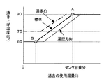
具体的な一例として図5に基づいて説明する。図5は沸き上げ温度と過去の使用湯量との関係を示す特性図であり、実線で示す特性が標準モードのときの沸き上げ温度と過去の使用湯量との関係を示す。図中に示すポイントAは、過去の使用熱量と最低貯湯熱量を合計した目標貯湯熱量Qaとタンク容量(例えば、300L)と沸き上げ温度によって決定される貯湯可能熱量Qbとが等しい強いポイントを示している。
【0065】
このポイントAの使用熱量の場合には、料金設定が最も低い深夜時間帯に沸き上がり温度を最大の90℃とすることで満タンまで貯湯することができる。従って、このときには、料金設定が最も高い昼間時間帯に沸き上げ運転を必要とせず電気代を安くすることができる。なお、上記過去の使用熱量は、第1実施形態で述べた使用湯量算出手段より求められた最大使用熱量Qoである。
【0066】
一方、図中に示すポイントBは、過去の使用湯量から沸き上げ温度を65℃としても一日の使用湯量が賄えるポイントを示しており、湯多めのモードの時には図中に一点鎖線で示す特性の沸き上げ温度にアップ(例えば、75℃)させることで貯湯可能熱量Qbを多めとすることができる。また、湯控えめのモードの時には図中に破線で示す特性の沸き上げ温度にダウン(例えば、65℃)させることで貯湯可能熱量Qbを控えめとすることができる。
【0067】
ここで、この沸き上げ温度の算出は数式6により求めることができる。
【0068】
【数式6】沸き上げ温度Tt=Qa/((タンク容量―最低貯湯量)×比重×4.18)+THWA
ただし、Qa:目標貯湯熱量
なお、上記、数式6は目標貯湯熱量Qaから沸き上げ温度Ttを算出するための沸き上げ温度算出手段であり、制御装置200内の図示しないROM内に設けられている・
以上の第2実施形態により貯湯式給湯装置によれば、沸き上げ温度を可変させることで、つまり、高めの沸き上げ温度であれば貯湯量を少なくでき、逆に、低めの沸き上げ温度であれば貯湯量を大きくするなどにより、複数の貯湯量の選択区分を標準沸き上げ温度を選択することでも良い。
【0069】
(他の実施形態)
以上の実施形態では、本発明を圧縮機、凝縮器、減圧器、蒸発器などのヒートポンプサイクルを構成する冷媒機能部品からなる超臨界ヒートポンプからなるヒートポンプユニット2に適用したが、これに限らず、一般のヒートポンプサイクルを構成する加熱手段に適用しても良い。さらに、貯湯タンク1内に電気ヒータが配設され、深夜電力を用いて給湯水を蓄える電気温水器に適用しても良い。
【図面の簡単な説明】
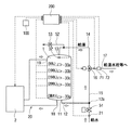
【図1】本発明の第1実施形態における貯湯式給湯装置の全体構成を示す模式図である。
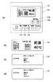
【図2】本発明の第1実施形態における(a)は操作盤100の構成を示す正面図、(b)は(a)に示す表示部130の通常表示形態を示す正面図、(c)および(d)は沸き上げ運転モード設定中における表示形態を示す正面図である。
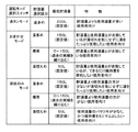
【図3】本発明の第1実施形態における沸き上げ運転モードの特性を示す特性図である。
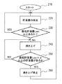
【図4】本発明の第1実施形態における制御装置200の沸き上げ運転の制御処理を示すフローチャートである。
【図5】本発明の第2実施形態における沸き上げ温度と過去の使用湯量との関係を示す特性図である。
【符号の説明】
1…貯湯タンク
2…ヒートポンプユニット(加熱手段)
100…操作盤(操作手段)
110…運転モード選択スイッチ(第1運転モード選択手段)
120a…給湯温度設定スイッチ、△高スイッチ(第2運転モード選択手段)
120b…給湯温度設定スイッチ、▽低スイッチ(第2運転モード選択手段)
200…制御装置(制御手段)[0001]
TECHNICAL FIELD OF THE INVENTION
The present invention relates to a hot water storage type hot water supply apparatus having a hot water storage tank for storing hot water for hot water heating by heating a heating means by a boiling operation, and in particular, a boiling operation without running out of hot water according to the amount of hot water used by a user. The selection of the operation mode to perform.
[0002]
[Prior art]
The conventional hot water storage type hot water supply device has a refrigerant compressor, a refrigerant flow path of a water heat exchanger, an expansion valve, a heat pump cycle in which an air heat exchanger is connected in a ring, and a hot water storage tank for storing hot water for hot water supply. The hot water storage tank is connected to the fluid flow path of the water heat exchanger, and a hot water supply fluid circuit provided with a fluid pump in the middle of the connection, and a hot water supply fluid amount in the hot water storage tank and the fluid temperature are detected. A hot water consumption calculating means for calculating the hot water consumption, and a control means for controlling the expansion valve, the fluid pump, and the refrigerant compressor to perform the boiling operation are provided.
[0003]
Then, during the late night hours when the fee setting is the lowest, the user uses hot water for hot water supply in the hot water storage tank, and the amount of hot water stored in the hot water storage tank reaches the first predetermined amount M1 (for example, 100 L of 60 ° C. hot water). When detecting the state of falling below, the control means starts the boiling operation, and the temperature of the fluid on the inlet side of the fluid flow path becomes equal to or higher than the first set temperature K1 or the amount of hot water stored in the hot water storage tank becomes the first predetermined amount M1 + α ( When α ≧ 0), the boiling operation is stopped.
[0004]
In the morning and evening hours when the charge setting is relatively low, the user uses hot water for hot water supply in the hot water storage tank, and the amount of hot water stored in the hot water storage tank is the second predetermined amount M2 (for example, 200 L of hot water at 60 ° C.). When the state is detected below the temperature, the control means starts the boiling operation, and the fluid temperature at the inlet side of the fluid flow path becomes equal to or higher than the second set temperature K2 or the amount of hot water stored in the hot water storage tank becomes the second predetermined amount M2 + β ( , Β ≧ 0), the boiling operation is stopped.
[0005]
Furthermore, in the daytime period when the charge is high, the user uses hot water for hot water supply in the hot water storage tank, and the amount of hot water stored in the hot water storage tank falls below a third predetermined amount M3 (for example, 200 L for 60 ° C. hot water). When the state is detected, the control means starts the boiling operation, and the temperature of the fluid on the inlet side of the fluid flow path becomes equal to or higher than the third set temperature K3, or the amount of hot water stored in the hot water storage tank becomes a third predetermined amount M3 + γ (γ ≧ 0), the boiling operation is stopped.
[0006]
Accordingly, in accordance with the pattern in which the user uses hot water for hot water supply in the hot water storage tank, the start determination condition of the hot water heating operation and the determination condition of the end of the hot water operation are independently set for each time zone. Then, control is performed such that the minimum amount of hot water stored in the hot water storage tank is always ensured to prevent running out of hot water in all time zones (for example, see Patent Document 1).
[0007]
[Patent Document 1]
JP-A-2002-206805 (
[0008]
[Problems to be solved by the invention]
However, according to
[0009]
In addition, in this type of hot water storage type hot water supply device, for example, a user uses a small amount of hot water from morning to late night (for example, from 7:00 to 23:00), and leaves a large amount of hot water at 23:00. In this case, the heat radiation in the unused period after the evening is wasted. Conversely, a user who uses a large amount of hot water a day and uses up the hot water in the hot water storage tank by the evening has a problem that the hot water runs out in the evening or at night. As described above, the amount of hot water used varies widely depending on the user. Therefore, for this purpose, a boiling operation for obtaining a relatively large hot water storage amount is generally performed.
[0010]
In view of the above, an object of the present invention is to expand the selection range of the boiling operation, so that hot water can be secured without running out of hot water and in accordance with the amount of hot water used. Another object of the present invention is to provide a hot water storage type hot water supply device.
[0011]
[Means for Solving the Problems]
In order to achieve the above object, the technical means described in
The operation means (100) includes a first operation mode selection means (110) for selecting one of the operation modes for boiling the heating means (2) in accordance with a plurality of hot water storage amount selection categories, and a first operation mode selection means (110). The second operation mode selection means (120a, 120a) selects the hot water storage amount selected by the one operation mode selection means (110) as a reference value, and selects any one of an upper limit, a lower limit, and a reference value for the reference value. 120b).
[0012]
According to the first aspect of the present invention, in this type of hot water supply device, the amount of hot water used varies depending on the user. Therefore, in the present invention, the selection range of the boiling operation is expanded, and the first operation mode selection operation means (110) for selecting any one according to the selection of the plurality of hot water storages is further selected. The second operation mode selection operation means (120a, 120b) for selecting any one of an upper limit, a lower limit, and a reference value with respect to the reference value using the stored hot water amount as a reference value, By the selection section, a boiling operation mode can be selected according to the amount of hot water used by the user. This makes it possible to secure a hot water storage amount according to the amount of hot water to be used from among a plurality of selection sections, as compared with the related art in which the boiling operation mode is fixed so as to have a large hot water storage amount. Therefore, there is no drainage, no wasteful heat radiation, and the electricity cost is reduced.
[0013]
In the invention described in
[0014]
According to the second aspect of the present invention, the amount of hot water stored is such that only the required amount is heated based on the accumulated data of the amount of hot water used in the past. Hot water storage can be secured.
[0015]
According to the third aspect of the present invention, the control means (200) calculates the used hot water amount from the hot water supply amount supplied from the hot water storage tank (1) within a predetermined period, and accumulates data. A target hot water amount obtained by adding the hot water amount obtained from the stored data calculated and stored by the hot water amount calculating means, and a boiling temperature for obtaining a boiling temperature from the target hot water amount. The second operation mode selecting means (120a, 120b) determines the reference value of the hot water storage amount and the upper and lower limits of the reference value based on the standard boiling temperature calculated by the standard boiling temperature calculating means. It is characterized by being selected.
[0016]
According to the third aspect of the present invention, in the above-mentioned second aspect, the selection range of the boiling operation is a selection section of a plurality of hot water storage amounts where the boiling temperature is constant. If the boiling temperature is lower, the amount of hot water can be reduced. Conversely, if the boiling temperature is lower, the amount of hot water can be increased.
[0017]
In the invention described in claim 4, the predetermined period is the past week, and the second operation mode selecting means (120a, 120b) sets the reference value of the hot water storage amount to the maximum used hot water amount among the accumulated data of the past one week. It is characterized by having.
[0018]
According to the invention described in claim 4, the amount of hot water used varies depending on environmental changes such as seasons. Therefore, in the present invention, since the maximum amount of hot water is used in the accumulated data of the past week, the amount of hot water stored according to the amount of hot water used can be secured. As a result, the hot water does not run out.
[0019]
In the invention described in claim 5, the second operation mode selection means (120a, 120b) selects the upper limit and the lower limit of the reference value of the hot water storage amount from a predetermined hot water storage amount including at least 0 set in advance. And
[0020]
According to the fifth aspect of the present invention, in the above-mentioned second aspect, the hot water storage amount for boiling only the necessary amount is automatically selected based on the accumulated data of the used hot water amount in the past. The present invention is not limited to this, and may be selected from a predetermined hot water storage amount set in advance. According to this, although the accuracy is slightly inferior to that of the second aspect, it is possible to secure the hot water storage amount according to the used hot water amount.
[0021]
In the invention described in claim 6, the first operation mode selecting means (110) is a full tank mode in which the selection section of the hot water storage capacity is at least a large capacity hot water storage capacity, and the hot water storage capacity according to the past hot water usage results. , And one of a saving mode in which the amount of hot water to be used is minimized.
[0022]
According to the invention described in claim 6, at least one of the full tank mode, the automatic mode, and the saving mode can be selected according to the amount of hot water used. This allows selection according to the amount of hot water used.
According to the invention described in claim 7, the operating means (100) is for selecting any one of the operating modes from the first operating mode selecting means (110) and the second operating mode selecting means (120a, 120b). A display is provided, and the second operation mode selection means (120a, 120b) is characterized in that the display of a plurality of operation modes is identified according to the selection.
[0023]
According to the invention described in claim 7, a plurality of operation mode displays are provided, and the display is identified according to the selection, so that the user can easily select and operate.
[0024]
Note that the reference numerals in parentheses of the above means indicate the correspondence with specific means of the embodiment described later.
[0025]
BEST MODE FOR CARRYING OUT THE INVENTION
(1st Embodiment)
Hereinafter, a hot water supply type hot water supply apparatus according to a first embodiment of the present invention will be described with reference to FIGS. FIG. 1 is a schematic diagram showing an overall configuration of a hot water supply type hot water supply apparatus. As shown in FIG. 1, the hot water supply type hot water supply apparatus of the present embodiment is a metal (for example, stainless steel) hot
[0026]
The
[0027]
On the other hand, an
[0028]
[0029]
The mixing
[0030]
A
[0031]
When the
[0032]
In addition, a
[0033]
A heat exchanger (not shown) is provided in a portion of the
[0034]
The
[0035]
Incidentally, according to the supercritical heat pump, hot water can be heated at a higher temperature (for example, about 85 ° C. to 90 ° C.) than a general heat pump cycle. The
[0036]
Next, on the upper outer wall surface of the hot
[0037]
[0038]
Therefore, the
[0039]
[0040]
Here, the
[0041]
First, the operation
[0042]
Here, the full tank mode is an operation mode in which a large-capacity hot water storage amount is desired to be ensured so as not to run out of hot water at all times. Therefore, when the minimum hot water storage amount becomes equal to or less than the predetermined value, the heating operation is controlled regardless of the time zone. The Random mode is an operation mode that learns from the past usage results to keep the hot water storage in the daytime at the optimum hot water storage, and optimizes the boiling operation in the daytime hours when the price setting is high. Is controlled. The midnight only mode is a mode for users who use only a small amount of hot water and is a boiling operation mode only when the charge setting is the lowest nighttime period.
[0043]
Next, in addition to setting the hot water supply temperature, the hot water supply
[0044]
FIG. 2B is a front view showing a normal display mode of the
[0045]
When the す る と
[0046]
In addition, as shown in FIG. 3, in the midnight only mode, a selection is made from among a large amount of hot water, a standard, and a low-priced water amount in the same manner as in the above-mentioned automatic mode. is there. Thereby, any one of the seven operation modes of the boiling operation can be selected.
[0047]
In each of the operation modes, a minimum hot water storage amount is set, and a predetermined minimum hot water storage value shown in FIG. However, in the standard, the minimum hot water storage value is set by automatically learning the minimum hot water storage value and the actual hot water storage amount from past results. Incidentally, when the minimum hot water storage amount is larger than the actual hot water storage amount, a value obtained by adding the predetermined amount A to the minimum hot water storage amount is set as the minimum hot water storage amount. When the minimum hot water storage amount is smaller than the actual hot water storage amount, the minimum hot water storage amount is the predetermined amount A. The value obtained by subtracting the above value is used as the minimum hot water storage amount. However, at this time, 0 <minimum hot water storage amount <150.
[0048]
Next, the operation of the hot water supply type hot water supply apparatus having the above configuration will be described with reference to FIG. FIG. 4 is a flowchart showing a control process of the boiling operation of the
[0049]
Next, in
[0050]
Here, the minimum amount of hot water, which is a start condition and an end condition of the boiling operation, is automatically changed and set based on a past actual value in the standard of the only-only mode and the late-night only mode. By the way, the past actual value is automatically selected by the used hot water amount calculating means which calculates and accumulates the used hot water amount from the hot water supply amount supplied from the hot
[0051]
The hot water consumption calculating means is provided in a ROM (not shown) of the
[0052]
Incidentally, an example of the calculation will be described below. First, the maximum used heat amount Qo for the past seven days is calculated. It is a value obtained by integrating the amount of heat used per liter used on the day of the day (for example, 23:00 the previous day to 23:00 on the day).
[0053]
[Formula 1] Qs1L = (Thw−THWA) × specific gravity / radiation loss coefficient
However, Qs1L: heat amount of 1 liter, Thw: hot water supply temperature, THWA: average water supply temperature, heat dissipation loss coefficient: 0.9
The average water supply temperature THWA is an average of the water supply temperature Ttwi supplied to the hot
[0054]
## EQU2 ## Specific gravity = (− 2 × 10 -6 × Thw 2 -2.7 × 10 -4 × Thw + 1.0058)
However, Thw: hot water supply temperature
Each time the
[0055]
[Formula 3] Qday = ΣQs1L
However, Qday: the amount of heat used per day, the integrated value of the amount of heat used per liter (23:00 on the previous day to 23:00 on the day), the amount of heat used for each day up to one week before, Qdayn, Qdayn- The maximum value of 1, Qdayn-2,..., Qdayn-5, and Qdayn-6 is defined as the maximum amount of heat Qo.
[0056]
## EQU4 ## The maximum amount of used heat Qo = Max (Qdayn, Qdayn-1, Qdayn-2, Qdayn-3, Qdayn-4, Qdayn-5, Qdayn-6) Here, the target heat storage amount is set so that the hot water is not drained. Set it to the safe side and use the maximum amount of heat. In addition, the average of the week may be used as the target heat storage amount, and the average may not be a weekly cycle. Then, the boiling temperature is converted into the maximum amount of hot water at a predetermined temperature (for example, 60 ° C.) based on the obtained maximum amount of used heat, and is set as a past actual value.
[0057]
[Formula 5] Maximum hot water consumption Lt = Qo / ((Tavg-THWA) × specific gravity × 4.18)
However, Tavg: average temperature in the tank
Accordingly, in the standard mode of only the hot water and the midnight only, it is possible to automatically select the minimum hot water storage amount based on the maximum used hot water amount according to the past recent results, so that the hot water is not run out and the optimum hot water storage is performed. There is no wasteful heat radiation because the amount can be reduced. In addition to the standard of each mode, a hot water operation and a hot water moderation are further provided, as shown in the characteristic column of FIG. 3, so that a hot water running operation that can secure an appropriate hot water storage amount according to the amount of hot water used by the user. Can be.
[0058]
According to the hot water supply type hot water supply apparatus of the first embodiment, in this type of hot water supply type hot water supply apparatus, the amount of hot water used varies depending on the user. Therefore, in the present invention, the selection range of the boiling operation is expanded, and an operation
[0059]
More specifically, the operation
[0060]
Further, the amount of hot water used varies depending on environmental changes such as seasons. Therefore, in the present invention, the boiling water operation is performed by obtaining the minimum hot water storage amount based on the maximum hot water usage in the accumulated data of the past week, so that the hot water storage amount corresponding to the hot water usage can be secured. As a result, the hot water does not run out.
[0061]
Furthermore, the hot water storage amount for boiling only the required amount is automatically selected based on the accumulated data of the used hot water amount in the past. However, the present invention is not limited to this, and it is also possible to select from a predetermined predetermined hot water storage amount. good. According to this, although the accuracy is slightly inferior to the amount of hot water used in the past, the amount of hot water stored according to the amount of hot water used can be secured.
[0062]
The
[0063]
(2nd Embodiment)
In the above-described first embodiment, the
[0064]
A specific example will be described with reference to FIG. FIG. 5 is a characteristic diagram showing the relationship between the boiling temperature and the past amount of hot water, and the characteristic indicated by the solid line shows the relationship between the boiling temperature and the past amount of hot water in the standard mode. Point A shown in the figure is a strong point at which the target hot water storage heat quantity Qa, which is the sum of the past used heat quantity and the minimum hot water storage heat quantity, the tank capacity (for example, 300 L), and the hot water storage heat quantity Qb determined by the boiling temperature are equal. ing.
[0065]
In the case of the used heat amount at the point A, the hot water can be stored up to the full tank by setting the boiling temperature to the maximum of 90 ° C. in the late night time zone when the charge is set to the lowest. Therefore, at this time, it is possible to reduce the electricity bill without the need for the boiling operation in the daytime hours when the charge setting is the highest. Note that the past used heat amount is the maximum used heat amount Qo obtained by the used hot water amount calculation means described in the first embodiment.
[0066]
On the other hand, point B shown in the figure indicates a point at which the amount of hot water used per day can be covered even when the boiling temperature is set at 65 ° C. based on the amount of hot water used in the past. By raising the temperature to the boiling temperature (for example, 75 ° C.), the heat storage capacity Qb can be increased. Further, in the hot water mode, the amount of heat Qb that can be stored can be reduced by lowering the temperature (for example, 65 ° C.) to the boiling temperature indicated by the broken line in the figure.
[0067]
Here, the calculation of the boiling temperature can be obtained by Expression 6.
[0068]
Formula 6: Boiling temperature Tt = Qa / ((tank capacity−minimum hot water storage amount) × specific gravity × 4.18) + THWA
Where Qa is the target hot water storage calorie
Equation 6 above is a boiling temperature calculating means for calculating the boiling temperature Tt from the target hot water storage amount Qa, and is provided in a ROM (not shown) in the
According to the hot water storage type hot water supply apparatus according to the above second embodiment, the amount of hot water can be reduced by changing the boiling temperature, that is, if the boiling temperature is high, the amount of hot water can be reduced. For example, the selection of a plurality of hot water storage amounts may be selected as the standard boiling temperature by increasing the amount of hot water storage.
[0069]
(Other embodiments)
In the above embodiment, the present invention is applied to the
[Brief description of the drawings]
FIG. 1 is a schematic diagram showing an overall configuration of a hot water supply type hot water supply apparatus according to a first embodiment of the present invention.
FIG. 2A is a front view showing a configuration of an
FIG. 3 is a characteristic diagram showing characteristics in a boiling operation mode in the first embodiment of the present invention.
FIG. 4 is a flowchart illustrating a control process of a boiling operation of the
FIG. 5 is a characteristic diagram showing a relationship between a boiling temperature and a past amount of hot water used in a second embodiment of the present invention.
[Explanation of symbols]
1. Hot water storage tank
2. Heat pump unit (heating means)
100 ... operation panel (operation means)
110 ... operation mode selection switch (first operation mode selection means)
120a: Hot water temperature setting switch, high switch (second operation mode selection means)
120b: Hot water supply temperature setting switch, low switch (second operation mode selection means)
200: control device (control means)
Claims (7)
前記貯湯タンク(1)内の水を使用湯量に応じた貯湯量に沸き上げ運転する加熱手段(2)と、
前記加熱手段(2)を沸き上げるための運転モードを選択して操作する操作手段(100)と、
前記操作手段(100)により出力される操作信号に基づいて前記加熱手段(2)を制御する制御手段(200)とを備える貯湯式給湯装置において、
前記操作手段(100)は、前記加熱手段(2)を沸き上げるための運転モードを複数の貯湯量の選択区分に応じていずれか一つを選択する第1運転モード選択手段(110)と、前記第1運転モード選択手段(110)により選択された貯湯量を基準値とし、その基準値に対して上限、下限および前記基準値のいずれか一つの貯湯量を選択する第2運転モード選択手段(120a、120b)とを有することを特徴とする貯湯式給湯装置。A hot water storage tank (1) for storing hot water for hot water supply inside,
Heating means (2) for boiling water in the hot water storage tank (1) to a hot water storage quantity corresponding to the hot water usage;
Operating means (100) for selecting and operating an operation mode for boiling the heating means (2);
And a control means (200) for controlling the heating means (2) based on an operation signal output by the operation means (100).
A first operation mode selection means (110) for selecting one of the operation modes for boiling the heating means (2) in accordance with a plurality of hot water storage amount selection sections; A second operation mode selection means for selecting a hot water storage amount selected by the first operation mode selection means (110) as a reference value and selecting any one of an upper limit, a lower limit, and the reference value for the reference value. (120a, 120b).
Priority Applications (1)
| Application Number | Priority Date | Filing Date | Title |
|---|---|---|---|
| JP2003024608A JP3855938B2 (en) | 2003-01-31 | 2003-01-31 | Hot water storage water heater |
Applications Claiming Priority (1)
| Application Number | Priority Date | Filing Date | Title |
|---|---|---|---|
| JP2003024608A JP3855938B2 (en) | 2003-01-31 | 2003-01-31 | Hot water storage water heater |
Publications (2)
| Publication Number | Publication Date |
|---|---|
| JP2004233003A true JP2004233003A (en) | 2004-08-19 |
| JP3855938B2 JP3855938B2 (en) | 2006-12-13 |
Family
ID=32953097
Family Applications (1)
| Application Number | Title | Priority Date | Filing Date |
|---|---|---|---|
| JP2003024608A Expired - Fee Related JP3855938B2 (en) | 2003-01-31 | 2003-01-31 | Hot water storage water heater |
Country Status (1)
| Country | Link |
|---|---|
| JP (1) | JP3855938B2 (en) |
Cited By (8)
| Publication number | Priority date | Publication date | Assignee | Title |
|---|---|---|---|---|
| JP2008157509A (en) * | 2006-12-21 | 2008-07-10 | Mitsubishi Electric Corp | Hot water storage hot water supply system |
| JP2011089669A (en) * | 2009-10-21 | 2011-05-06 | Panasonic Corp | Storage type hot water supply device |
| JP2011094895A (en) * | 2009-10-30 | 2011-05-12 | Panasonic Corp | Storage water heater |
| JP2011106812A (en) * | 2011-03-11 | 2011-06-02 | Denso Corp | Storage water heater |
| JP2011117662A (en) * | 2009-12-03 | 2011-06-16 | Panasonic Corp | Storage type water heater |
| JP2012063058A (en) * | 2010-09-15 | 2012-03-29 | Mitsubishi Electric Corp | Storage-type water heating system |
| JP2018071902A (en) * | 2016-10-31 | 2018-05-10 | 三菱電機株式会社 | Storage type hot water supply system |
| JP2021025707A (en) * | 2019-08-06 | 2021-02-22 | 日立グローバルライフソリューションズ株式会社 | Storage tank-type water heater |
Families Citing this family (1)
| Publication number | Priority date | Publication date | Assignee | Title |
|---|---|---|---|---|
| JP2010084959A (en) * | 2008-09-30 | 2010-04-15 | Noritz Corp | Storage type hot water supply system |
-
2003
- 2003-01-31 JP JP2003024608A patent/JP3855938B2/en not_active Expired - Fee Related
Cited By (9)
| Publication number | Priority date | Publication date | Assignee | Title |
|---|---|---|---|---|
| JP2008157509A (en) * | 2006-12-21 | 2008-07-10 | Mitsubishi Electric Corp | Hot water storage hot water supply system |
| JP2011089669A (en) * | 2009-10-21 | 2011-05-06 | Panasonic Corp | Storage type hot water supply device |
| JP2011094895A (en) * | 2009-10-30 | 2011-05-12 | Panasonic Corp | Storage water heater |
| JP2011117662A (en) * | 2009-12-03 | 2011-06-16 | Panasonic Corp | Storage type water heater |
| JP2012063058A (en) * | 2010-09-15 | 2012-03-29 | Mitsubishi Electric Corp | Storage-type water heating system |
| JP2011106812A (en) * | 2011-03-11 | 2011-06-02 | Denso Corp | Storage water heater |
| JP2018071902A (en) * | 2016-10-31 | 2018-05-10 | 三菱電機株式会社 | Storage type hot water supply system |
| JP2021025707A (en) * | 2019-08-06 | 2021-02-22 | 日立グローバルライフソリューションズ株式会社 | Storage tank-type water heater |
| JP6995804B2 (en) | 2019-08-06 | 2022-01-17 | 日立グローバルライフソリューションズ株式会社 | Hot water storage tank type water heater |
Also Published As
| Publication number | Publication date |
|---|---|
| JP3855938B2 (en) | 2006-12-13 |
Similar Documents
| Publication | Publication Date | Title |
|---|---|---|
| JP6097933B2 (en) | Hot water storage water heater | |
| JP4453662B2 (en) | Heat pump type water heater | |
| JP2006336937A (en) | Hot water storage water heater | |
| JP6507954B2 (en) | Water heater | |
| JP3855938B2 (en) | Hot water storage water heater | |
| JP5567519B2 (en) | Hot water storage bath water heater | |
| JP3778106B2 (en) | Heat pump water heater | |
| JP5109300B2 (en) | Hot water storage hot water heater | |
| JP2004324905A (en) | Hot water storage system | |
| JP2010112680A (en) | Hot water storage water heater | |
| JP3869426B2 (en) | Hot water storage water heater | |
| JP3749194B2 (en) | Hot water storage water heater | |
| JP3901108B2 (en) | Hot water storage water heater | |
| JP4448488B2 (en) | Hot water storage water heater | |
| JP3840574B2 (en) | Water heater | |
| JP3857951B2 (en) | Bath equipment | |
| JP2004233002A (en) | Hot water storage system | |
| JP5979042B2 (en) | Water heater | |
| JP3974029B2 (en) | Hot water storage water heater | |
| JP4100126B2 (en) | Water heater | |
| JP2006138513A (en) | Heat pump type hot water supply heating device | |
| JP2009079824A (en) | Hot water storage water heater | |
| JP4304950B2 (en) | Water heater | |
| JPH05118660A (en) | Storage type hot water supplying apparatus | |
| JP2006308178A (en) | Water heater |
Legal Events
| Date | Code | Title | Description |
|---|---|---|---|
| A621 | Written request for application examination |
Free format text: JAPANESE INTERMEDIATE CODE: A621 Effective date: 20050406 |
|
| A977 | Report on retrieval |
Free format text: JAPANESE INTERMEDIATE CODE: A971007 Effective date: 20060803 |
|
| TRDD | Decision of grant or rejection written | ||
| A01 | Written decision to grant a patent or to grant a registration (utility model) |
Free format text: JAPANESE INTERMEDIATE CODE: A01 Effective date: 20060822 |
|
| A61 | First payment of annual fees (during grant procedure) |
Free format text: JAPANESE INTERMEDIATE CODE: A61 Effective date: 20060904 |
|
| R150 | Certificate of patent or registration of utility model |
Ref document number: 3855938 Country of ref document: JP Free format text: JAPANESE INTERMEDIATE CODE: R150 Free format text: JAPANESE INTERMEDIATE CODE: R150 |
|
| FPAY | Renewal fee payment (event date is renewal date of database) |
Free format text: PAYMENT UNTIL: 20090922 Year of fee payment: 3 |
|
| FPAY | Renewal fee payment (event date is renewal date of database) |
Free format text: PAYMENT UNTIL: 20100922 Year of fee payment: 4 |
|
| FPAY | Renewal fee payment (event date is renewal date of database) |
Free format text: PAYMENT UNTIL: 20100922 Year of fee payment: 4 |
|
| FPAY | Renewal fee payment (event date is renewal date of database) |
Free format text: PAYMENT UNTIL: 20110922 Year of fee payment: 5 |
|
| FPAY | Renewal fee payment (event date is renewal date of database) |
Free format text: PAYMENT UNTIL: 20110922 Year of fee payment: 5 |
|
| FPAY | Renewal fee payment (event date is renewal date of database) |
Free format text: PAYMENT UNTIL: 20120922 Year of fee payment: 6 |
|
| FPAY | Renewal fee payment (event date is renewal date of database) |
Free format text: PAYMENT UNTIL: 20120922 Year of fee payment: 6 |
|
| FPAY | Renewal fee payment (event date is renewal date of database) |
Free format text: PAYMENT UNTIL: 20130922 Year of fee payment: 7 |
|
| R250 | Receipt of annual fees |
Free format text: JAPANESE INTERMEDIATE CODE: R250 |
|
| R250 | Receipt of annual fees |
Free format text: JAPANESE INTERMEDIATE CODE: R250 |
|
| R250 | Receipt of annual fees |
Free format text: JAPANESE INTERMEDIATE CODE: R250 |
|
| R250 | Receipt of annual fees |
Free format text: JAPANESE INTERMEDIATE CODE: R250 |
|
| S802 | Written request for registration of partial abandonment of right |
Free format text: JAPANESE INTERMEDIATE CODE: R311802 |
|
| R350 | Written notification of registration of transfer |
Free format text: JAPANESE INTERMEDIATE CODE: R350 |
|
| R250 | Receipt of annual fees |
Free format text: JAPANESE INTERMEDIATE CODE: R250 |
|
| R250 | Receipt of annual fees |
Free format text: JAPANESE INTERMEDIATE CODE: R250 |
|
| LAPS | Cancellation because of no payment of annual fees |