JP2004233378A - Optical connector cleaning unit and optical connector cleaning tool - Google Patents
Optical connector cleaning unit and optical connector cleaning tool Download PDFInfo
- Publication number
- JP2004233378A JP2004233378A JP2003009759A JP2003009759A JP2004233378A JP 2004233378 A JP2004233378 A JP 2004233378A JP 2003009759 A JP2003009759 A JP 2003009759A JP 2003009759 A JP2003009759 A JP 2003009759A JP 2004233378 A JP2004233378 A JP 2004233378A
- Authority
- JP
- Japan
- Prior art keywords
- optical connector
- cleaning
- unit
- drive assist
- connector
- Prior art date
- Legal status (The legal status is an assumption and is not a legal conclusion. Google has not performed a legal analysis and makes no representation as to the accuracy of the status listed.)
- Granted
Links
Images









Classifications
-
- B—PERFORMING OPERATIONS; TRANSPORTING
- B08—CLEANING
- B08B—CLEANING IN GENERAL; PREVENTION OF FOULING IN GENERAL
- B08B1/00—Cleaning by methods involving the use of tools
- B08B1/30—Cleaning by methods involving the use of tools by movement of cleaning members over a surface
-
- B—PERFORMING OPERATIONS; TRANSPORTING
- B08—CLEANING
- B08B—CLEANING IN GENERAL; PREVENTION OF FOULING IN GENERAL
- B08B11/00—Cleaning flexible or delicate articles by methods or apparatus specially adapted thereto
-
- G—PHYSICS
- G02—OPTICS
- G02B—OPTICAL ELEMENTS, SYSTEMS OR APPARATUS
- G02B6/00—Light guides; Structural details of arrangements comprising light guides and other optical elements, e.g. couplings
- G02B6/24—Coupling light guides
- G02B6/36—Mechanical coupling means
- G02B6/38—Mechanical coupling means having fibre to fibre mating means
- G02B6/3807—Dismountable connectors, i.e. comprising plugs
- G02B6/3833—Details of mounting fibres in ferrules; Assembly methods; Manufacture
- G02B6/3866—Devices, tools or methods for cleaning connectors
Landscapes
- Mechanical Coupling Of Light Guides (AREA)
Abstract
Description
【0001】
【発明の属する技術分野】
本発明は、コネクタハウジング内の光コネクタの接合端面を清掃する光コネクタ清掃ユニットおよび光コネクタ清掃工具に関する。
【0002】
【従来の技術】
周知のように、プラグ−アダプタ−プラグ結合方式の光コネクタは、アダプタとなるコネクタハウジングに、対向する両側から挿入、接続された光コネクタ(プラグ)同士が、該アダプタ内で接続されるものである。
また、プラグ−レセプタクル結合方式の光コネクタは、レセプタクルとなる光コネクタハウジング内に、接続される一方の光コネクタ(フェルールなど)が保持されており、これに対向して前記レセプタクルに光コネクタ(プラグ)が挿入されて接続されるものである。
アダプタやレセプタクルなどのコネクタハウジング内での光コネクタ同士の接続は、各光コネクタの接合端面に臨む光ファイバの端面同士を突き合わせ接合することで実現される。
【0003】
コネクタハウジングに光コネクタを挿入して突き合わせ接続する際、光コネクタの接合端面にゴミや埃、油分などの汚れが付着していると、着脱時の損傷や、伝送損失の増大などの原因になるため、突き合わせ接続に先立って、接合端面を清掃する必要がある。従来、この接合端面の清掃は、アルコールを含浸させた綿棒やテープタイプのクリーナーなどの清掃具を用い、この清掃具を直接手で把持して、清掃具を光コネクタの接合端面に当接させて拭き取り清掃することが一般的である(例えば特許文献1参照)。
【0004】
【特許文献1】
特開2000−284147号公報
【0005】
【発明が解決しようとする課題】
ところで、上述のような清掃具では、コネクタハウジング内の光コネクタの接合端面を清掃するためには、他方の光コネクタを挿入するためのコネクタハウジング内の空間(コネクタ挿入穴)に清掃具を挿入して、当該接合端面を清掃することになる。清掃箇所である光コネクタの接合端面はコネクタ挿入穴の奥に位置し、非常に見づらいことから、清掃具が接合端面に対して確実に当接しているか否かや、さらには清掃の進捗状況などが確認しづらく、清掃が必ずしも良好になされないおそれがあった。
また、作業時に清掃具をコネクタハウジングの内壁などに触れさせてしまうと、清掃具が汚れてしまい、これを接合端面に当接させると、かえって汚れの付着や接合端面の損傷などのおそれがあることから、清掃具の挿入は慎重に注意深く行う必要があり、作業が面倒であった。
【0006】
一方、清掃すべき光コネクタをコネクタハウジングから抜去すれば、接合端面は見やすくなり、また、この接合端面に清掃工具を当接させることは容易になるが、清掃後、光コネクタをコネクタハウジングに挿入する作業は、光コネクタにゴミや埃などが再び付着しないように、慎重に行う必要があり、この光コネクタの着脱に要する手間と合わせて、作業が著しく煩雑になるため、問題となっていた。
【0007】
従って、本発明の課題は、光コネクタをコネクタハウジングに挿入した状態で、当該光コネクタの接合端面を容易かつ確実に清掃することができる光コネクタ清掃ユニットおよび清掃工具を提供することを課題とする。
【0008】
【課題を解決するための手段】
前記課題を解決するため、本発明は、コネクタハウジング内の光コネクタの接合端面に対する相対運動により前記接合端面を拭き取り清掃する清掃部材と、前記清掃部材を運動させる駆動機構とを搭載し、前記駆動機構に動力を与える駆動補助機構を連結することが可能な連結部を備えることを特徴とする光コネクタ清掃ユニットを提供する。
【0009】
この光コネクタ清掃ユニットにおいては、ユニット本体と、このユニット本体から突出して設けられ、前記コネクタハウジングに挿入可能に形成されている挿入部とを備え、前記挿入部をコネクタハウジングに挿入することにより、前記挿入部の前記ユニット本体からの突出先端に位置させておかれた清掃部材を、前記接合端面に対して位置決めして当接させることができるようになっていることが好ましい。
【0010】
さらに本発明は、上述の光コネクタ清掃ユニットの前記連結部に、前記駆動補助機構を備えた駆動補助ユニットを連結したことを特徴とする光コネクタ清掃工具を提供する。
このような光コネクタ清掃工具においては、駆動補助ユニットが、光コネクタ清掃工具を把持するための把持部を備え、この把持部に対する光コネクタ清掃ユニットの向きが複数通りに変更可能となっているようにすることができる。
【0011】
【発明の実施の形態】
以下、実施の形態に基づいて、本発明を説明する。
図1〜7は、本発明の光コネクタ清掃工具(以下、単に「清掃工具」という)の一実施の形態を示す図である。
図1および図2に示すように、この清掃工具6は、詳しくは後述するように、光コネクタ(プラグ)の接合端面を清掃するための光コネクタ清掃ユニット1(以下、単に「清掃ユニット」という)に、駆動補助ユニット5を連結できるようにしたものである。
清掃ユニット1と駆動補助ユニット5とを連結する具体的構成は特に限定されないが、例えば、図2(b)に示すように、駆動補助ユニット5の前縁部5aの両側部に形成された係合部5bを、清掃ユニット1の下縁部の係合部1aに係合させることにより行うことができる。
【0012】
本実施の形態の清掃ユニット1および清掃工具6が適用される光コネクタ(プラグ)およびコネクタハウジング(アダプタ)は、ここでは図6、7に示すように、JIS C 5982等に規定されるMPO形光コネクタ(MPO:Multifiber Push On)である。
光コネクタ7は、JIS C 5981等に規定されるMT形光コネクタフェルール71(MT:Mechanically Transferable。以下、単にフェルールという)をプラスチック製でスリーブ状のハウジング72の先端部に収容した構成の光コネクタプラグであり、全体が外観扁平な断面形状に形成されている。
以下の説明では、この光コネクタ7の扁平形状の短辺側に対応する方向(図7の上下方向)を厚さ方向、長辺側に対応する方向を幅方向(図7の紙面に垂直な方向)ということがある。また、光コネクタ7の厚さ方向および幅方向に対応して、この光コネクタ7と接続されるコネクタハウジング8ならびにコネクタハウジング8に挿入される清掃ユニット1の挿入部20についても同様に、厚さ方向および幅方向ということがある。
【0013】
フェルール71の接合端面71aには、所定の個数の光ファイバ穴71bが配列されるように開口している。光ファイバ73は、その先端を光ファイバ穴71b(微細孔)に挿通することにより、他の光コネクタと突き合わせ接続可能に成端されるとともに、光コネクタ7の内部を貫通して光コネクタ7の後端から引き出されている。
光コネクタ7後端から引き出された光ファイバ73は、ハウジング72の接続方向後端側(図7の左側)に設けられたブーツ74に収納されることにより、光コネクタ7後端付近での急激な曲げ等が防止されている。
【0014】
光ファイバ73としては、特に限定はなく、例えば単心または多心の光ファイバ心線、この光ファイバ心線をチューブに収納した光ファイバコードなどが採用可能である。前記光ファイバ心線や前記光ファイバコードの場合、該光ファイバ心線等の先端の被覆を除去して露出させた裸光ファイバを、フェルール71の光ファイバ穴71bに挿入して、突き合わせ接続可能に成端される。
【0015】
フェルール71の接合端面71aにおいて、光ファイバ穴71bが開口している領域の両側には、ガイドピン穴71cが設けられている。フェルール71同士は、ガイドピン穴71cに挿入されて接合端面71aから突出するように設けられる突出部材75(ガイドピン)を介して、周知のガイドピン嵌合方式の位置決め機構によって高精度に位置決めして、接合端面71a同士を突き合わせ接合して接続されるようになっており、これにより、各フェルール71に成端されている光ファイバ73同士が光接続されるようになっている。
【0016】
アダプタ8は、概略スリーブ状に形成されており、対向する両側に形成されるコネクタ挿入口81から光コネクタ7を挿入することにより、アダプタ8の内部に形成されたコネクタ収容穴82に収容することができるようになっている。
光コネクタ7は、アダプタ8のコネクタ挿入口81から挿入されると、挿入方向からずれた方向への変位を規制されつつ、コネクタ収容穴82に収容される。2個の光コネクタ7をアダプタ8に挿入すると、該アダプタ8内でフェルール71同士が突き合わされ、これにより、各フェルール71に成端されている光ファイバ73同士が光接続されるようになっている。
【0017】
上記コネクタ7の接合端面71aの清掃に適用できる清掃ユニット1は、図3(a)、(b)に詳しく図示したように、内部に清掃部材2が収容された概略ケース状のユニット本体10と、このユニット本体10から突出して設けられ、アダプタ8のコネクタ収容穴82に挿入可能に形成された挿入部20と、清掃部材2を運動させる駆動機構3と、前記駆動機構3に動力を与える駆動補助機構(後述)を連結することが可能な連結部4を備えている。
【0018】
ここではユニット本体10は、プラスチック等からなる第1および第2のケース半体11、12による二つ割り構造になっている。特に図示しないが、例えば、第1のケース半体11の内側に突出して形成された嵌合ピンと、第2のケース半体12の内側に突設されたボスに設けられた嵌合穴とを嵌合させることにより、一体化できるように構成されている。
ユニット本体10は、挿入部20に向かって先細り形状となっている。
【0019】
清掃部材2はここではテープであり、このテープ2としては、特に限定されるものではなく、公知の適当な清浄布(不織布や織布)をテープ状に加工したものを採用することができ、例えば、ポリエステルやナイロンなどの極細の繊維からなるものなどが例示される。
テープ2の幅は、光コネクタ7における接合端面71aに露出するすべての光ファイバの端面とその周囲を一度に拭ける程度となっている。
【0020】
ケース半体11、12の収納空間35には、駆動機構3として、テープ2を送り移動するテープ送り機構が設けられている。
このテープ送り機構3は、テープ2を巻装した供給リール30と、使用後のテープ2を巻き取って回収する巻取リール31と、テープ2を操作する操作ダイヤル34を備えている。
第1のケース半体11の内側(収納空間35に臨んだ側)の面には、供給リール30が回転可能に装着された供給リール支持軸32と、巻取リール31が回転可能に装着された巻取リール支持軸33が設けられている。
【0021】
巻取リール支持軸33の外周には、巻取リール31と同心となるように、操作ダイヤル34が装着されている。
この操作ダイヤル34は、第1のケース半体11の側面に設けられた窓11aから、一部、ユニット本体10の外に露出されるようになっている。操作ダイヤル34を手などで操作して所定の方向に回転させることにより、巻取リール31が回転してテープ2を巻き取るとともに、供給リール30から未使用のテープ2が繰り出されるようになっている。上記窓11aは、ユニット本体10の側面に開口しているので、操作ダイヤル34は、清掃ユニット1を片手で持ったときでも、清掃ユニット1を持った側の手の指で容易に操作できる。
【0022】
操作ダイヤル34の半径は、巻取リール31の半径より大きくなっている。その結果、テープ2が巻取リール31に巻き取られる長さは、操作ダイヤル34の操作量(該操作ダイヤル34の外周に沿った変位量)より、上記半径比の分だけ小さくなる。このため、テープ2の微小な送り量が容易に達成される。
【0023】
供給リール30と巻取リール31との間では、テープ2は、ピン状のテープガイド36に沿って、両ケース半体11、12の間に形成された収納空間35内に張り回されている。そして、その途中で、挿入部20内に収容された後述のヘッド部材23に巻き掛けられている。
【0024】
このテープ送り機構3は、手指により操作ダイヤル34を操作することによって駆動することができる。さらに、この清掃ユニット1は、動力源となる駆動補助ユニット5を連結部4を介して連結することにより、テープ送り機構3を駆動することができるようになっている。
駆動補助ユニット5は、テープ送り機構3に動力を与える駆動補助機構50を備えている。駆動補助機構50の具体的な構成としては、例えば、後述する第2の実施の形態の駆動補助ユニット205に組み込まれたものを用いることができる。
【0025】
連結部4は、具体的には、図3(a)、(b)に示すように、軸44aに軸支されたギア44と、巻取リール支持軸33および軸44aの外周に装着されたベルト車41、42と、これらのベルト車41、42に巻き掛けられたベルト43とから構成されている。ギア44が回転すると、このギア44の回転力がベルト車41、42の回転によりベルト43を介して巻取リール支持軸33に伝達され、これにより、テープ送り機構3が駆動される。
【0026】
図3、4に示すように、ユニット本体10の後縁部には、開口46が形成されている。この開口46は、蓋45の係止爪45aを開口46の端縁46aに係合させることにより閉じられるようになっている。
蓋45を外した状態では、駆動補助ユニット5の前縁部をユニット本体10の後縁部に嵌合させることにより、駆動補助ユニット5内に組み込まれた駆動補助機構50のギア51を連結部4のギア44と噛合させることができる。ギア51は、図示しない電動モータなどの動力源により、駆動されるようになっており、ギア44、51を噛合させた状態では、前記動力源の動力が連結部4を介してテープ送り機構3に伝達され、テープ2が送られる。
前記動力源は、図1、2に示した駆動スイッチ52により駆動のオン・オフを切り替えられるようになっている。
なお、動力源としては、電動モータに限定されず、ゴムやゼンマイなどを用いることもできる。
【0027】
さらにこの清掃ユニット1は、ユニット本体10から突出して設けられ、前記コネクタハウジングに挿入可能に形成されている挿入部20を備えている。
挿入部20は、コネクタハウジング8に挿入することにより、該挿入部20のユニット本体10からの突出先端に位置させておかれた清掃部材2(テープ)を、光コネクタ7の接合端面71aに対して位置決めして当接させることができるようになっている。
【0028】
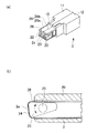
具体的には、図5(a)に示すように、挿入部20はユニット本体10と同じく二つ割り構造となっていて、それぞれのケース半体11、12と一体に形成された挿入部半体20a、20bを、ケース半体11、12の一体化に伴って一体化することにより形成されるようになっている。挿入部20の外面の幅方向両側には、光コネクタ7の接合端面71aから突出した突出部材(ガイドピン)75との干渉を避けるように形成された凹部22が形成されている。
つまり、挿入部20は、コネクタハウジング8に挿入された際に、接合端面71aから突出する突出部材75との干渉を避けるための凹部22を有している。
【0029】
挿入部20内には、テープ2が巻き掛けられるヘッド部材23が収容されている。ヘッド部材23は、図5(b)に示す平面視で概略、挿入部20の挿入方向に細長い三角形ないし台形状となっており、その挿入方向先端側(図5(b)の左側)が当接面24となっている。ヘッド部材23は、両挿入部半体20a、20bの間に挟持される支軸25によって、当接面24の挿入部20の挿入方向に対する向きが変えられるように、当該支軸25を中心とした上下方向の回転が可能なように支持されている。
これにより、清掃部材2の前記接合端面71aに当接する当接部2aが、該清掃部材2の挿入方向に対する向きを変えられるようになっている。
【0030】
ヘッド部材23は、先端の当接面24側が、挿入部20内に収容された側よりも厚さ方向の寸法が大きくなっている。これにより、ヘッド部材23の当接面24が光コネクタ7の接合端面71aに当接するために充分な寸法を確保するとともに、ヘッド部材23が支軸25を中心として回転した際に、テープ2が挿入部20の内壁に押し付けられてしまうことが抑制されるようになっている。
【0031】
挿入部20の先端には、開口部26が形成されている。この開口部26からは、ヘッド部材23の当接面24と、この当接面24に沿って巻き掛けられたテープ2とが露出されるようになっている。
なお、特に図示していないが、開口部26から露出されたヘッド部材23およびテープ2を保護するためのキャップやカバーなどを挿入部20の先端に取り付けて、清掃ユニット1を使用しないときに上記テープ2等を保護できるようにしてもよいことは勿論である。
【0032】
挿入部20には、ユニット本体10側に段差15が設けられている。この段差15は、挿入部20をアダプタ8のコネクタ収容穴82に挿入したときに、該段差15がアダプタ8のコネクタ挿入口81の周縁部81aに当接することにより、挿入部20のコネクタ収容穴82への進入深さが深くなりすぎるのを防ぐためのものである。
【0033】
この清掃ユニット1および清掃工具6の使用方法の一例を説明する。
清掃工具6の挿入部20をアダプタ8のコネクタ挿入口81から挿入すると、挿入部20は、外面がアダプタ8の内壁80aにより位置決めされながらコネクタ収容穴82に進入する。段差15がコネクタ挿入口81の周縁部81aにぶつかるところまで挿入部20を押し込むことにより、清掃部材2は、光コネクタ7の接合端面71aの適切な位置(ここでは、光ファイバ穴71bとその周辺)に位置決めされて当接させられる。
【0034】
ヘッド部材23は、その当接面24が光コネクタ7の接合端面71aと当接したときの反作用により、支軸25を中心として回転するので、接合端面71aが挿入部20の挿入方向に対して傾斜していたとしても、テープ2が接合端面71aに当接する当接部2aをぴったり合わせることができる。
光コネクタ7の接合端面71aにガイドピン75が突出していた場合でも、ガイドピン75は、挿入部20に設けられた凹部22に収容されるので、挿入部20は、ガイドピン75と干渉することなく、コネクタ収容穴82内に収容することができる。
【0035】
操作ダイヤル34を所定量回転させると、巻取リール31の回転と連動してテープ2が運動し、このテープ2により接合端面71aが拭かれるので、接合端面71aに付着しているゴミや埃、油分などの汚れが、テープ2により確実に拭き取られる。
清掃部材2の当接部2aは、清掃中も挿入部20がアダプタ8のコネクタ収容穴82に位置決めされ、位置ずれすることなく、均等な押圧力で接合端面71aを拭き取り清掃することができる。また、挿入部20を、ごく軽い力で、アダプタ8内に支持することができ、作業性がよい。
ガイドピン75は、清掃部材2から離隔された凹部22に収容されているので、清掃部材2とガイドピン75との干渉も防止される。
【0036】
拭き取られた汚れは、テープ2に付着して巻取リール31に巻き取られる方向に移動するので、使用後のテープ2はもはや挿入部20の開口部26から露出されることはなく、汚れが接合端面71aに再び付着するおそれがない。
従って、接合端面71aを極めて清浄に清掃することができる。
清掃後、清掃ユニット1を挿入したときと反対の方向に引くことにより、挿入部20を容易に引き抜くことができる。
【0037】
清掃ユニット1に駆動補助ユニット5を取り付けたときには、テープ2は駆動補助ユニット5の動力により動かすことができる。また、一つの駆動補助ユニット5に対して多数の清掃ユニット1を用意し、テープ2を使い切るたびに清掃ユニット1を交換するようにすれば、現場で清掃ユニット1を開いてテープ2を交換する必要がない。従って、清掃の作業性が極めて高いものとなる。
【0038】
図8〜16は、本発明の清掃ユニットおよび清掃工具の第2の実施の形態を示す図である。これらの図において、図1〜7で用いたものと同じ符号は、同一または同様の構成であることを示し、重複する説明を省略する。
本実施の形態の清掃工具206は、第1の実施の形態の清掃工具6の改変例であり、上記第1の実施の形態のものと同様に、清掃ユニット201と、この清掃ユニット201に連結可能とされた駆動補助ユニット205とから構成されるものである。
【0039】
図9〜11に示すように、本実施の形態の清掃ユニット201は、第1の実施の形態の清掃ユニット201と同様に、内部に清掃部材2が収容されたケース状のユニット本体10と、このユニット本体10から突出して設けられ、アダプタ8のコネクタ収容穴82に挿入可能に形成された挿入部20と、清掃部材2を運動させる駆動機構3と、前記駆動機構3に動力を与える駆動補助機構(後述)を連結することが可能な連結部204とを備えている。
【0040】
ここでは、連結部204は、巻取リール支持軸33の外周に装着されたギア291と、ケース半体11に取り付けられた軸293の外周に装着されたギア292とから構成され、ギア291、292は、互いに噛み合わされている。上記第1の実施の形態のものと同様に、清掃ユニット201と駆動補助ユニット205とを連結させ、ギア292に駆動補助ユニット205のギア245(図12参照)を噛み合わせると、ギア292が駆動補助ユニット205により駆動されるようになり、ギア292の回転力がギア291を介して巻取リール支持軸33に伝達され、これにより、テープ送り機構3が駆動される。
なお、本実施の形態の清掃ユニット201では、ユニット本体10の、挿入部20に近い部分19は、細く形成されており、この部分の内部には、この細径部分19の補強のための突壁19aが設けられている。この突壁19aによれば、この突壁19aにより、供給リール30からヘッド部材23に向かう、清浄であるべき清掃テープ2の経路と、ヘッド部材23から巻取リール31に向かう、拭き取り清掃により汚染された清掃テープ2の経路とが仕切られるので、清掃テープ2の汚れの移行が抑制される効果も奏される。
【0041】
駆動補助ユニット205は、図12〜16に詳しく図示するように、ケース210内に収容された駆動補助機構207と、ケース210の前縁部に設けられ、清掃ユニット201と駆動補助ユニット205を連結できるようにするための連結機構208とを有している。
ケース210は、プラスチック等からなる第1および第2のケース半体211、212による二つ割り構造で構成されており、ケース半体211、212を向かい合わせて周縁部同士を嵌め合わせ、ネジ213、214によるネジ止めすることなどにより、一体化できるようになっている。
【0042】
ケース210の前端側(図13の左側)には、駆動補助機構207のギア245の歯先円の一部をケース210外に露出するための開口部266が設けられている。
ケース半体211、212の上部に形成された切欠部211a、212aは、ケース210を組み立てたときに、操作スイッチ250(後述)をケース210外に露出させる窓210aとなるものである。
【0043】
連結機構208は、一対の押さえ部材として、ケース210の前端側上部の板バネ262と、この板バネ262に対向してケース210の前端側下部に配置された梃子状の係止部材264を備えて構成されている。
係止部材264は、前端側が係止部264a、後端側が操作部264bとなっている。また、係止部材264は、係止部264aと操作部264bとの間の中央部に挿通される軸265により、両ケース半体211、212に挟持されるようになっている。
係止部材264は、操作部264aをケース210の下面に向かって押圧すると、係止部264aを板バネ262から離して開くようになっている。係止部材264は、操作部264bの裏面側に当接された板バネ263により付勢されており、操作部264bへの操作を解除すると、係止部264a側を板バネ262に近づけて閉じるようになっている。
【0044】
このような連結機構208は、係止部材264の操作部264bを操作して、押さえ部材である板バネ262と係止部材264との間隔を開き、ケース210の前端縁261に清掃ユニット201をあてがってから係止部材264への操作力を解除することにより、清掃ユニット201の後端部を押さえ込んで保持するようになっている。
【0045】
図15に詳しく図示するように、駆動補助機構207は、電池270等の電源により作動する動力源として、モータ221を有している。モータ221の端子221bは、図示しない配線により、電源に接続されている。
電池270は、モータ221の下側(図14の下側、図15における紙面方向奥側)に配設される電池ボックス271に入れられる。電池270の交換のため、ケース半体211には、着脱自在の蓋273により閉鎖可能となる開口部272が設けられている。
なお、電源としては、他分野の電気機器において一般的に行われているように、ACアダプタを装着するジャックを駆動補助機構207の電気回路に設け、外部の交流電源を利用できるようにしてもよい。また、電源として、電池と、ACアダプタからの交流とのどちらかを選択して利用するようにすることも可能である。
【0046】
モータ221の駆動軸221aは、固定部材(ねじ)226により、ジョイント224の一端に固定されている。また、ジョイント224の他端には、固定部材(ねじ)227により、かさ歯車225が固定されている。ジョイント224の中途部は、ケース210に固定された軸受台222の穴222aに装着された軸受223により、転動可能に保持されている。
軸受台222のケース210への固定は、ケース半体212にフランジ部222bを突き合わせてネジ222cでネジ止めし、さらに、ケース半体211に設けられた穴211bを通して、軸受台222のネジ穴222dにネジ214を螺着させることにより行われる。
【0047】
かさ歯車225は、その回転軸に垂直な回転軸を有するかさ歯車233とかみ合わされている。かさ歯車225は、フランジ付き軸231の軸部231aの外周に、キー232を介してフランジ付き軸231からトルクを伝達することができるように装着されている。また、フランジ付き軸231のフランジ部231bとギア234の側面とに挟まれて保持されている。
【0048】
ギア(平歯車)234は、上記ギア(平歯車)245と噛み合うように配置され、フランジ付き軸231の軸部231aに形成されたネジ部(図示せず)に締結されるナット236により、上記軸部231aから脱落しないように保持されている。ギア234とナット236の間には、ワッシャ235が介在させられている。フランジ付き軸231の両端は、両ケース半体211、212の内面に装着された軸受237、238により、回転可能に保持されている。
【0049】
ギア245は、3本のネジ246により、カム242のネジ穴242bに螺着されている。カム242とギア245との間には軸受243が介在されている。軸受243は、軸241の外周に装着されている。軸241の両端は、両ケース半体211、212の内面に装着された軸受247、248により、回転可能に保持されている。軸受243と軸受247との間には、ギア245が軸241の長手方向に位置ずれするのを防ぐため、スペーサとしてのスリーブ244が、軸241の外周に装着されている。
【0050】
カム242は、外周に沿って等間隔に溝242a(個数は特に限定されないが、図14では3個として図示している)を有している。このカム242の回転量を検知するセンサとして、作動片(ホイール付レバー)256aのホイールがカム242の外周に当接するように、リミットスイッチ256がケース210にネジ256bにより螺着されている。リミットスイッチ256は、ホイールがカム242の溝242aに嵌まり込んだときに電流をOFFにし、溝242aから外れたときに電流をONにするようになっている。すなわち、ギア245の回転量が、リミットスイッチ256からの出力として電気的に検知できる(回転量検知手段)ようになっている。
【0051】
ケース210の上側には、レバー式の操作スイッチ250が配設されている。操作スイッチ250は、軸251の両端をケース半体211、212のそれぞれに設けられた穴252(図14には、ケース半体211側の穴252のみが示されている)に保持させることにより、ケース210に回動可能に取り付けられる。操作スイッチ250の裏側には、リミットスイッチ255が配置されており、操作スイッチ250が押されると、リミットスイッチ255の作動片(ホイール付レバー)255aが押されてトリガーとなる電気信号が出力されるようになっている。また、操作スイッチ250は、押された後、バネ253により、元の位置に復帰させるようになっている。
リミットスイッチ255は、ネジ255bにより、ケース210(ケース半体211)に取り付けられている。
【0052】
また、ケース210(ケース半体212)には、ネジ284aにより回路基板284が取り付けられている。この回路基板284には、IC等の制御部274が配置されるようになっている。図16に模式的に示すように、この制御部274は、電源270、モータ221、操作スイッチ255の操作を検知するリミットスイッチ255、ギア245の回転量を検知するセンサ(リミットスイッチ)256と接続されている。
【0053】
本実施の形態における、駆動補助機構207の動作を説明する。操作スイッチ250を押し操作すると、リミットスイッチ255から出力されるトリガー信号に基づいて、制御部274の制御によりモータ221に電源270から電気が供給されて、モータ221の作動が開始され、清掃テープ2が駆動されて光コネクタの清掃が開始される。清掃テープ2が一定量(カム242の溝242aの間隔に基づく)送られたことをセンサ256が検知して、センサ256との回路が断絶されると、モータ221が停止され、清掃テープ2も停止する。このように、操作スイッチ250を押すだけで、常に一定量のテープ2が自動的に送られるような制御機能を駆動補助ユニット205に持たせれば、個人差による清掃時間の変動が抑制され、高い清掃効果を容易に得ることが可能になる。
ただし、操作スイッチ250の操作時間に基づいて、その操作の間、モータ221が駆動され、操作スイッチ250の操作解除によってモータ221が停止するような制御機能を駆動補助ユニット205に採用したとしても、本発明に包含されることは言うまでもない。
また、センサとしては、ギア245の回転を検知するものに限定されることなく、例えば、モータ221の駆動開始からの時間を測定するタイマなどを用いることもできる。
【0054】
回路基板284には電源270から回路への電気の供給をオン・オフするためのスライドスイッチ282が取り付けられている。スライドスイッチ282をケース210外から操作するため、概略矩形状の操作スライダ280が設けられている。操作スライダ280は、長手方向の両端に切欠280aが設けられ、この切欠280aにネジ283を通してケース210(ケース半体211)に螺着することにより、2本のネジ283の軸部の範囲内でスライド可能になっている。操作スライダ280の裏側(図14の紙面手前側)には、スライドスイッチ282のスライダ282aに装着される穴281aを有するボス281が形成されている。そのため、操作スライダ280をスライド操作することにより、スライドスイッチ282を操作することができる。
【0055】
このような清掃工具206によれば、第1の実施の形態において図6、7に示したのと同様にして、光コネクタの接合端面を清掃することができる。この際、清掃ユニット201に連結される駆動補助ユニット205により、清掃ユニット201の駆動機構3に動力を与えることができる。もちろん、清掃ユニット201単独でも、操作ダイヤル34により手動で清掃テープ2を駆動して清掃することも可能である。
【0056】
図17〜20は、本発明の清掃ユニットおよび清掃工具の第3の実施の形態を示す図である。
これらの図において、図1〜7で用いたものと同じ符号は、同一または同様の構成であることを示し、重複する説明を省略する。
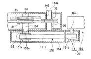
図17、18に示すように、本実施の形態の清掃工具106は、清掃ユニット101に、駆動補助ユニット105を後述のように連結することにより構成される。
【0057】
清掃ユニット101は、第1の実施の形態において述べたものと同様の構成の挿入部20および駆動機構3を備えている。巻取リール支持軸33の先端に延出された割りスリーブ状の連結部104を有している。また、供給リール支持軸32の内面には、ユニット本体10を幅方向に貫通する透孔142が形成されている。
【0058】
また、図17、図19に示すように、駆動補助ユニット105は、駆動スイッチ156を有する把持部155と、この把持部155に対して駆動軸153を介して回転可能に連結された伝動部151とを備えている。図17に仮想線として示すように駆動軸153は、例えば、ネジやラチェット機構などの公知の適切な構成(不図示)により、伝動部151と把持部155との角度を変更できるようになっている。
【0059】
伝動部151は、清掃ユニット1の連結部104と連結可能な連結軸152と、連結軸152および駆動軸153の外周に装着されたベルト車151a、151bと、これらのベルト車151a、151bに巻き掛けられたベルト151cを備え、これらは筐体154に収納されている。駆動補助機構150は、図示しない動力源(電動モータなど)によって駆動される駆動軸153の回転力を、伝動部151のベルト151cや連結軸152等を介して、清掃ユニット1の駆動機構3に伝達することができるように構成されている。
【0060】
図19に示すように、連結軸152は、先端が筐体154の外に臨んでおり、突端に、連結部104の切欠部141と嵌合可能に形成された突起152aを有している。
清掃ユニット101と駆動補助ユニット105とは、連結部104の切欠部141と、連結軸152の突起152aとを嵌合させるとともに、伝動部151を収納する筐体154の側部から突出された突出部154aを透孔142に嵌入させることにより、安定にガタツキなく連結される。
【0061】
このような清掃工具106によれば、第1の実施の形態において図6、7に示したのと同様にして、光コネクタの接合端面を清掃することができる。この際、清掃ユニット101に連結される駆動補助ユニット105により、駆動機構3に動力を与えることができる。
【0062】
また、伝動部151と把持部155との角度を変更することにより、把持部155に対する清掃ユニット101の向きを変更することができる。これにより、図20に示すように、例えば成端箱190などの高いところや低いところにあるコネクタハウジング8内の光コネクタ7の接合端面を清掃することを容易に行うことができる。しかも、駆動スイッチ156が把持部155に設けられているので、清掃部材2の駆動のオン・オフを、清掃工具106を把持した手で切り換えることができる。
【0063】
以上、本発明を好適な実施の形態に基づいて説明してきたが、本発明はこの実施の形態のみに限定されるものではなく本発明の要旨を逸脱しない範囲で種々の改変が可能である。
例えば、光コネクタ清掃工具の具体的形状は、前記実施の形態に限定されず、適用対象の光コネクタの形状に応じて適宜変更可能である。
【0064】
ユニット本体において、挿入部は、突出方向の複数箇所に、互いに異なるコネクタハウジングへの挿入によってコネクタハウジング内で位置決めされる単位挿入部が形成されており、挿入部の各単位挿入部は、挿入部の突出方向の位置が相対的に後ろ側に位置する単位挿入部を収容することができる全てのコネクタハウジングに、挿入可能であるように形成されているものとすることができる。このような清掃ユニットによれば、それぞれの単位挿入部により、挿入部を互いに異なるコネクタハウジングに対して位置決めされるように挿入することができ、1つの清掃ユニットを用いて、コネクタハウジングの異なる複数の種類やサイズなどに対応して、このコネクタハウジング内の光コネクタの接合端面の清掃を行うことができる。
【0065】
また、挿入部は、ユニット本体に対して複数種類の挿入部が交換可能なものとして構成することもできる。これにより、ユニット本体を変更することなく、挿入部の変更のみによって、コネクタハウジングの種類やサイズなどに対応して、このコネクタハウジング内の光コネクタの接合端面の清掃を行うことができる。
【0066】
清掃部材としては、テープの他、綿棒など、公知の適切なものが採用できる。
上記実施の形態の清掃ユニットにおいては、挿入部は、該挿入部先端に形成された開口部を除いて、清掃部材をすっかり覆うようになっていたが、必ずしも、これに限定されない。挿入部をコネクタハウジングに挿入するに、清掃部材がコネクタハウジングの内壁などに接触して汚染されるのを防げるのであれば、形状や構造は特に限定されず、必ずしもハウジング状である必要はない。
【0067】
駆動補助ユニットが、把持部に対する光コネクタ清掃ユニットの向きが複数通りに変更可能となっている構成としては、清掃ユニットと駆動補助ユニットとの連結部において、取り付けの向きが複数とおりに変更できるような構成としてもよい。
【0068】
【発明の効果】
以上説明したように、本発明の光コネクタ清掃ユニットは、コネクタハウジング内の光コネクタの接合端面に対する相対運動により前記接合端面を拭き取り清掃する清掃部材と、前記清掃部材を運動させる駆動機構とを搭載し、前記駆動機構に動力を与える駆動補助機構を連結することが可能な連結部を備えているので、駆動機構を用いて清掃部材を駆動することにより、光コネクタの接合端面の拭き取り清掃を楽に行うことができる。
また、清掃部材を駆動補助機構の動力を用いて駆動することにより、光コネクタの接合端面の拭き取り清掃を一層楽に行うことができる。
【0069】
さらに、ユニット本体から突出して設けられ、コネクタハウジングに挿入可能に形成された挿入部を有し、この挿入部の前記ユニット本体からの突出先端に位置させておかれた清掃部材を、前記接合端面に対して位置決めして当接させることができるように構成された光コネクタ清掃ユニットによれば、挿入部をコネクタハウジングに挿入するだけで、清掃部材をコネクタハウジング内の光コネクタの接合端面に正しく当接することができる。また、清掃部材をコネクタハウジング内に挿入する際に、清掃部材のコネクタハウジング内壁への接触が防止される。従って、当該清掃部材の汚染を抑制することができる。しかも、清掃部材を運動させて拭き取り清掃する際にも、清掃部材の接合端面に対する当接位置を適切な位置に維持することが容易になるので、接合端面の良好な清掃状態を容易かつ確実に得ることができる。清掃工具を手で支持しても、手ブレによる、清掃部材の当接位置のズレが起こりにくい。また、挿入部を、ごく軽い力でコネクタハウジング内に支持することができるので、作業性がよい。
【0070】
本発明の光コネクタ清掃工具は、上述の光コネクタ清掃ユニットの前記連結部に、前記駆動補助機構を備えた駆動補助ユニットを連結したものであるので、清掃部材を駆動補助機構の動力により駆動することができ、光コネクタの接合端面を拭き取り清掃する作業を楽に行うことができる。しかも、連結部の連結を解除して光コネクタ清掃ユニットを交換することにより、清掃部材を容易に交換することができる。
【0071】
駆動補助ユニットが、光コネクタ清掃工具を把持するための把持部を備え、この把持部に対する光コネクタ清掃ユニットの向きが複数通りに変更可能となっていれば、光コネクタやコネクタハウジングが、比較的狭い場所や高所、低所などにあったとしても、清掃作業を容易に行うことができる。
【図面の簡単な説明】
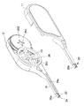
【図1】本発明の清掃工具の第1の実施の形態における清掃ユニットと駆動補助ユニットを示す斜視図である。
【図2】(a)第1実施の形態の清掃工具の斜視図である。(b)図2(a)のA−A線に沿う横断面図である。
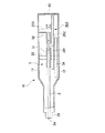
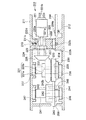
【図3】第1実施の形態の清掃ユニットを(a)上方から図示した断面図、(b)正面から図示した部分切欠断面図である。
【図4】第1実施の形態の清掃工具における駆動補助機構と連結部との連結状態の一例を示す部分切欠断面図である。
【図5】第1実施の形態の清掃ユニットにおける挿入部を示す(a)斜視図、(b)縦断面図である。
【図6】第1実施の形態の清掃ユニットの挿入部を、光コネクタが収容されたアダプタに挿入する状態を示す分解斜視図である。
【図7】第1実施の形態の清掃ユニットの挿入部を、光コネクタが収容されたアダプタに挿入した状態を示す断面斜視図である。
【図8】本発明の清掃工具の第2の実施の形態を示す正面図である。
【図9】第2の実施の形態の清掃工具に係る清掃ユニットを示す(a)正面図、(b)斜視図である。
【図10】図9の清掃ユニットを示す分解斜視図である。
【図11】図9の清掃ユニットを上方から図示した断面図である。
【図12】第2の実施の形態の清掃工具に係る駆動補助ユニットを示す(a)正面図、(b)斜視図である。
【図13】図12の駆動補助ユニットを示す分解斜視図(その1)である。
【図14】図12の駆動補助ユニットを示す分解斜視図(その2)である。
【図15】図12の駆動補助ユニットのB−B線に沿う断面図である。
【図16】図12の駆動補助ユニットの電気回路の概略構成を示す模式図である。
【図17】本発明の清掃工具の第3の実施の形態を示す斜視図である。
【図18】第3の実施の形態の清掃ユニットを(a)上方から図示した縦断面図、(b)正面から図示した部分切欠断面図である。
【図19】第3の実施の形態の清掃工具における駆動補助機構と連結部との連結状態の一例を示す部分切欠断面図である。
【図20】第3の実施の形態の清掃工具において、把持部に対する清掃ユニットの向きを変更した状態の一例を上方から図示した平面図である。
【符号の説明】
1…光コネクタ清掃ユニット(清掃ユニット)、2…清掃部材(テープ)、3…駆動機構(テープ送り機構)、4…連結部、5…駆動補助ユニット、6…光コネクタ清掃工具(清掃工具)、7…光コネクタ、8…コネクタハウジング、10…ユニット本体、20…挿入部、44…ギア、50…駆動補助機構、51…ギア、71a…接合端面、101…光コネクタ清掃ユニット(清掃ユニット)、104…連結部、105…駆動補助ユニット、106…光コネクタ清掃工具(清掃工具)、150…駆動補助機構、155…把持部、201…光コネクタ清掃ユニット(清掃ユニット)、204…連結部、205…駆動補助ユニット、206…光コネクタ清掃工具(清掃工具)、207…駆動補助機構、245…ギア、250…操作スイッチ、274…制御部、292…ギア。[0001]
TECHNICAL FIELD OF THE INVENTION
The present invention relates to an optical connector cleaning unit and an optical connector cleaning tool for cleaning a joint end face of an optical connector in a connector housing.
[0002]
[Prior art]
As is well known, an optical connector of a plug-adapter-plug coupling type is such that optical connectors (plugs) inserted and connected to a connector housing serving as an adapter from opposite sides thereof are connected within the adapter. is there.
In a plug-receptacle coupling type optical connector, one optical connector (such as a ferrule) to be connected is held in an optical connector housing serving as a receptacle, and an optical connector (plug) is connected to the receptacle in opposition thereto. ) Is inserted and connected.
Connection between optical connectors in a connector housing such as an adapter or a receptacle is realized by abutting and joining the end faces of optical fibers facing the joining end faces of the optical connectors.
[0003]
When the optical connector is inserted into the connector housing and butt-connected, if dirt, dust, oil, or other dirt adheres to the joint end surface of the optical connector, it may cause damage during attachment / detachment and increase transmission loss. Therefore, it is necessary to clean the joint end surface before the butt connection. Conventionally, this joint end face has been cleaned with a cleaning tool such as a cotton swab impregnated with alcohol or a tape-type cleaner.The cleaning tool is directly grasped by hand, and the cleaning tool is brought into contact with the joint end face of the optical connector. It is common to wipe off and clean (for example, see Patent Document 1).
[0004]
[Patent Document 1]
JP 2000-284147 A
[0005]
[Problems to be solved by the invention]
In the cleaning tool described above, in order to clean the joint end face of the optical connector in the connector housing, the cleaning tool is inserted into a space (connector insertion hole) in the connector housing into which the other optical connector is inserted. Then, the joining end surface is cleaned. The junction end face of the optical connector, which is the cleaning location, is located behind the connector insertion hole and is very difficult to see, so whether the cleaning tool is securely in contact with the junction end face, and the progress of cleaning, etc. However, there was a risk that cleaning was not always performed satisfactorily.
Also, if the cleaning tool is brought into contact with the inner wall of the connector housing during the operation, the cleaning tool is contaminated, and if the cleaning tool is brought into contact with the joining end face, there is a possibility that the contaminant adheres and the joining end face is damaged. Therefore, it was necessary to carefully and carefully insert the cleaning tool, and the operation was troublesome.
[0006]
On the other hand, if the optical connector to be cleaned is removed from the connector housing, the joining end face becomes easier to see and the cleaning tool can be easily brought into contact with this joining end face, but after cleaning, the optical connector is inserted into the connector housing. Must be carefully performed so that dust and dirt do not adhere to the optical connector again, and the work becomes extremely complicated in addition to the labor required for attaching and detaching the optical connector, which has been a problem. .
[0007]
Therefore, an object of the present invention is to provide an optical connector cleaning unit and a cleaning tool that can easily and reliably clean the joint end surface of the optical connector in a state where the optical connector is inserted into the connector housing. .
[0008]
[Means for Solving the Problems]
In order to solve the above-described problems, the present invention includes a cleaning member for wiping and cleaning the joint end surface by a relative movement with respect to a joint end surface of an optical connector in a connector housing, and a driving mechanism for moving the cleaning member, Provided is an optical connector cleaning unit, comprising: a connecting portion capable of connecting a drive assist mechanism for supplying power to the mechanism.
[0009]
The optical connector cleaning unit includes a unit main body, and an insertion portion provided to protrude from the unit main body and formed to be insertable into the connector housing, and by inserting the insertion portion into the connector housing, It is preferable that a cleaning member positioned at a distal end of the insertion portion protruding from the unit main body can be positioned and brought into contact with the joining end surface.
[0010]
Further, the present invention provides an optical connector cleaning tool, wherein a driving auxiliary unit having the driving auxiliary mechanism is connected to the connecting portion of the optical connector cleaning unit.
In such an optical connector cleaning tool, the drive auxiliary unit includes a grip portion for gripping the optical connector cleaning tool, and the orientation of the optical connector cleaning unit with respect to the grip portion can be changed in a plurality of ways. Can be
[0011]
BEST MODE FOR CARRYING OUT THE INVENTION
Hereinafter, the present invention will be described based on embodiments.
1 to 7 are diagrams showing an embodiment of an optical connector cleaning tool (hereinafter, simply referred to as "cleaning tool") of the present invention.
As shown in FIGS. 1 and 2, the
The specific configuration for connecting the
[0012]
The optical connector (plug) and the connector housing (adapter) to which the
The
In the following description, the direction corresponding to the short side of the flat shape of the optical connector 7 (vertical direction in FIG. 7) is the thickness direction, and the direction corresponding to the long side is the width direction (perpendicular to the plane of FIG. 7). Direction). Similarly, the thickness of the
[0013]
The
The
[0014]
The
[0015]
Guide pin holes 71c are provided on both sides of a region where the
[0016]
The
When the
[0017]
As shown in detail in FIGS. 3A and 3B, the
[0018]
Here, the
The
[0019]
Here, the cleaning
The width of the
[0020]
A tape feed mechanism that feeds and moves the
The
A supply
[0021]
An
The
[0022]
The radius of the
[0023]
Between the
[0024]
The
The
[0025]
Specifically, as shown in FIGS. 3A and 3B, the connecting
[0026]
As shown in FIGS. 3 and 4, an opening 46 is formed in the rear edge of the unit
With the
The power source can be turned on and off by a
Note that the power source is not limited to the electric motor, and rubber or a mainspring may be used.
[0027]
Further, the
The
[0028]
Specifically, as shown in FIG. 5 (a), the
That is, the
[0029]
A
Thus, the
[0030]
The
[0031]
An
Although not particularly shown, a cap or a cover for protecting the
[0032]
The
[0033]
An example of how to use the
When the
[0034]
The
Even when the
[0035]
When the
The abutting
Since the
[0036]
Since the wiped dirt adheres to the
Therefore, the joining
After cleaning, the
[0037]
When the drive assist
[0038]
8 to 16 are views showing a cleaning unit and a cleaning tool according to a second embodiment of the present invention. In these drawings, the same reference numerals as those used in FIGS. 1 to 7 indicate the same or similar configuration, and redundant description will be omitted.
The
[0039]
As shown in FIGS. 9 to 11, the
[0040]
Here, the connecting
In the
[0041]
The
The
[0042]
An
The
[0043]
The
The locking
When the operating
[0044]
Such a
[0045]
As illustrated in detail in FIG. 15, the
The
As a power supply, a jack for attaching an AC adapter is provided in the electric circuit of the
[0046]
The
To fix the
[0047]
The
[0048]
The gear (spur gear) 234 is disposed so as to mesh with the gear (spur gear) 245, and the nut (236) is fastened to a screw portion (not shown) formed on a
[0049]
The
[0050]
The
[0051]
Above the
The
[0052]
Further, a
[0053]
The operation of the
However, even if the control function that the
Further, the sensor is not limited to a sensor that detects the rotation of the
[0054]
The
[0055]
According to such a
[0056]
17 to 20 are views showing a cleaning unit and a cleaning tool according to a third embodiment of the present invention.
In these drawings, the same reference numerals as those used in FIGS. 1 to 7 indicate the same or similar configuration, and redundant description will be omitted.
As shown in FIGS. 17 and 18, the
[0057]
The
[0058]
As shown in FIGS. 17 and 19, the
[0059]
The
[0060]
As shown in FIG. 19, the
The
[0061]
According to such a
[0062]
Further, by changing the angle between the
[0063]
As described above, the present invention has been described based on the preferred embodiments, but the present invention is not limited to only the embodiments, and various modifications can be made without departing from the gist of the present invention.
For example, the specific shape of the optical connector cleaning tool is not limited to the above-described embodiment, and can be appropriately changed according to the shape of the optical connector to which the optical connector cleaning tool is applied.
[0064]
In the unit body, the insertion portion has unit insertion portions that are positioned in the connector housing by being inserted into different connector housings at a plurality of locations in the protruding direction, and each unit insertion portion of the insertion portion has an insertion portion. May be formed so as to be insertable into all the connector housings that can accommodate the unit insertion section whose position in the protruding direction is relatively rearward. According to such a cleaning unit, the insertion unit can be inserted by each unit insertion portion so as to be positioned with respect to the different connector housings, and a plurality of different connector housings can be inserted using one cleaning unit. According to the type and size of the optical connector, the joining end face of the optical connector in the connector housing can be cleaned.
[0065]
Further, the insertion section may be configured such that a plurality of types of insertion sections can be exchanged with respect to the unit body. Accordingly, it is possible to clean the joint end surface of the optical connector in the connector housing according to the type and size of the connector housing only by changing the insertion portion without changing the unit body.
[0066]
As the cleaning member, a known appropriate member such as a cotton swab can be adopted in addition to the tape.
In the cleaning unit of the above embodiment, the insertion section completely covers the cleaning member except for the opening formed at the tip of the insertion section, but is not necessarily limited to this. The shape and structure are not particularly limited as long as the cleaning member can be prevented from coming into contact with the inner wall of the connector housing and being contaminated when the insertion portion is inserted into the connector housing.
[0067]
As a configuration in which the drive auxiliary unit can change the direction of the optical connector cleaning unit with respect to the gripping section in a plurality of ways, the connection direction between the cleaning unit and the drive auxiliary unit can be changed in a plurality of ways. It is good also as a structure.
[0068]
【The invention's effect】
As described above, the optical connector cleaning unit of the present invention includes the cleaning member for wiping and cleaning the joint end surface by the relative movement of the optical connector in the connector housing with respect to the joint end surface, and the drive mechanism for moving the cleaning member. And, since the driving mechanism is provided with a connecting portion capable of connecting a driving auxiliary mechanism for supplying power to the driving mechanism, the cleaning member is driven by using the driving mechanism, thereby facilitating wiping and cleaning of the joint end face of the optical connector. It can be carried out.
In addition, by driving the cleaning member using the power of the drive assist mechanism, the wiping and cleaning of the joint end surface of the optical connector can be performed more easily.
[0069]
The cleaning member further includes an insertion portion protruding from the unit main body and formed to be insertable into the connector housing. According to the optical connector cleaning unit configured to be able to be positioned and contacted with respect to the optical connector cleaning unit, simply inserting the insertion portion into the connector housing allows the cleaning member to be correctly attached to the joint end surface of the optical connector in the connector housing. Can abut. Further, when the cleaning member is inserted into the connector housing, contact of the cleaning member with the inner wall of the connector housing is prevented. Therefore, contamination of the cleaning member can be suppressed. In addition, even when the cleaning member is moved to perform wiping cleaning, it is easy to maintain the contact position of the cleaning member with the joint end surface at an appropriate position, so that a good cleaning state of the joint end surface can be easily and reliably performed. Obtainable. Even if the cleaning tool is supported by hand, displacement of the contact position of the cleaning member due to camera shake does not easily occur. Further, since the insertion portion can be supported in the connector housing with a very small force, workability is good.
[0070]
In the optical connector cleaning tool of the present invention, since the driving auxiliary unit having the driving auxiliary mechanism is connected to the connecting portion of the optical connector cleaning unit, the cleaning member is driven by the power of the driving auxiliary mechanism. Accordingly, the work of wiping and cleaning the joint end surface of the optical connector can be easily performed. In addition, the cleaning member can be easily replaced by releasing the connection of the connecting portion and replacing the optical connector cleaning unit.
[0071]
If the drive assist unit has a grip portion for gripping the optical connector cleaning tool, and the orientation of the optical connector cleaning unit with respect to the grip portion can be changed in a plurality of ways, the optical connector and the connector housing can be relatively shaped. The cleaning operation can be easily performed even in a narrow place, a high place, a low place, and the like.
[Brief description of the drawings]
FIG. 1 is a perspective view showing a cleaning unit and a driving auxiliary unit in a cleaning tool according to a first embodiment of the present invention.
FIG. 2A is a perspective view of a cleaning tool according to the first embodiment. (B) It is a cross-sectional view along the AA line of FIG.
3A is a cross-sectional view illustrating the cleaning unit according to the first embodiment from above, and FIG. 3B is a partially cutaway cross-sectional view illustrating the cleaning unit according to the first embodiment.
FIG. 4 is a partially cutaway sectional view showing an example of a connection state between a drive assist mechanism and a connection portion in the cleaning tool according to the first embodiment.
FIGS. 5A and 5B are a perspective view and a longitudinal sectional view illustrating an insertion portion in the cleaning unit according to the first embodiment. FIGS.
FIG. 6 is an exploded perspective view showing a state where the insertion section of the cleaning unit according to the first embodiment is inserted into an adapter in which the optical connector is housed.
FIG. 7 is a cross-sectional perspective view showing a state where the insertion section of the cleaning unit according to the first embodiment is inserted into an adapter in which the optical connector is accommodated.
FIG. 8 is a front view illustrating a cleaning tool according to a second embodiment of the present invention.
9A is a front view and FIG. 9B is a perspective view illustrating a cleaning unit according to a cleaning tool according to a second embodiment.
FIG. 10 is an exploded perspective view showing the cleaning unit of FIG. 9;
11 is a cross-sectional view illustrating the cleaning unit of FIG. 9 from above.
12A is a front view and FIG. 12B is a perspective view showing a drive assist unit according to a cleaning tool according to a second embodiment.
FIG. 13 is an exploded perspective view (part 1) showing the drive assist unit of FIG. 12;
FIG. 14 is an exploded perspective view (part 2) showing the driving auxiliary unit of FIG. 12;
15 is a cross-sectional view of the driving auxiliary unit of FIG. 12 taken along line BB.
FIG. 16 is a schematic diagram showing a schematic configuration of an electric circuit of the driving auxiliary unit of FIG.
FIG. 17 is a perspective view showing a cleaning tool according to a third embodiment of the present invention.
18A is a vertical cross-sectional view illustrating a cleaning unit according to a third embodiment from above, and FIG. 18B is a partially cutaway cross-sectional view illustrating the cleaning unit according to a third embodiment.
FIG. 19 is a partially cutaway sectional view showing an example of a connection state between a drive assist mechanism and a connection portion in the cleaning tool according to the third embodiment.
FIG. 20 is a plan view illustrating, from above, an example of a state in which the direction of the cleaning unit with respect to the grip portion is changed in the cleaning tool according to the third embodiment.
[Explanation of symbols]
DESCRIPTION OF
Claims (7)
前記駆動機構に動力を与える駆動補助機構(50、150、207)を連結することが可能な連結部(4、104、204)を備えることを特徴とする光コネクタ清掃ユニット(1、101、201)。A cleaning member (2) for wiping and cleaning the joint end surface by relative movement of the optical connector (7) in the connector housing (8) with respect to the joint end surface (71a), and a drive mechanism (3) for moving the cleaning member are mounted. And
An optical connector cleaning unit (1, 101, 201) comprising a connection part (4, 104, 204) capable of connecting a drive assist mechanism (50, 150, 207) for supplying power to the drive mechanism. ).
前記挿入部をコネクタハウジングに挿入することにより、前記挿入部の前記ユニット本体からの突出先端に位置させておかれた清掃部材を、前記接合端面に対して位置決めして当接させることができるようになっていることを特徴とする請求項1に記載の光コネクタ清掃ユニット。A unit main body (10), and an insertion portion (20) protruding from the unit main body and formed to be insertable into the connector housing,
By inserting the insertion portion into the connector housing, the cleaning member positioned at the tip of the insertion portion protruding from the unit main body can be positioned and brought into contact with the joining end surface. The optical connector cleaning unit according to claim 1, wherein:
前記制御部は、操作スイッチの操作に基づいて駆動補助機構を始動させるようになっていることを特徴とする請求項3に記載の光コネクタ清掃工具。The drive assist unit includes a drive assist mechanism, an operation switch (250), and a control unit (274) that controls driving of the drive assist mechanism.
4. The optical connector cleaning tool according to claim 3, wherein the control unit starts the drive assist mechanism based on an operation of an operation switch. 5.
前記制御部は、操作スイッチの操作に基づいて駆動補助機構を始動させ、前記センサにより検知された清掃部材の運動量に基づいて駆動補助機構の駆動を停止するように制御するものであることを特徴とする請求項4に記載の光コネクタ清掃工具。The drive assist unit further includes a sensor (256) for directly or indirectly detecting the momentum of the cleaning member,
The controller controls the drive assist mechanism to start based on an operation of an operation switch, and to stop driving the drive assist mechanism based on a momentum of the cleaning member detected by the sensor. The optical connector cleaning tool according to claim 4, wherein
Priority Applications (2)
| Application Number | Priority Date | Filing Date | Title |
|---|---|---|---|
| JP2003009759A JP4015032B2 (en) | 2002-12-02 | 2003-01-17 | Optical connector cleaning unit and optical connector cleaning tool |
| US10/349,197 US7243390B2 (en) | 2002-12-02 | 2003-01-22 | Cleaning unit for optical connector and cleaning tool for optical connector |
Applications Claiming Priority (2)
| Application Number | Priority Date | Filing Date | Title |
|---|---|---|---|
| JP2002350469 | 2002-12-02 | ||
| JP2003009759A JP4015032B2 (en) | 2002-12-02 | 2003-01-17 | Optical connector cleaning unit and optical connector cleaning tool |
Publications (2)
| Publication Number | Publication Date |
|---|---|
| JP2004233378A true JP2004233378A (en) | 2004-08-19 |
| JP4015032B2 JP4015032B2 (en) | 2007-11-28 |
Family
ID=32396314
Family Applications (1)
| Application Number | Title | Priority Date | Filing Date |
|---|---|---|---|
| JP2003009759A Expired - Fee Related JP4015032B2 (en) | 2002-12-02 | 2003-01-17 | Optical connector cleaning unit and optical connector cleaning tool |
Country Status (2)
| Country | Link |
|---|---|
| US (1) | US7243390B2 (en) |
| JP (1) | JP4015032B2 (en) |
Cited By (2)
| Publication number | Priority date | Publication date | Assignee | Title |
|---|---|---|---|---|
| WO2011108303A1 (en) * | 2010-03-05 | 2011-09-09 | 株式会社フジクラ | Optical connector cleaning tool |
| JPWO2022244038A1 (en) * | 2021-05-17 | 2022-11-24 |
Families Citing this family (20)
| Publication number | Priority date | Publication date | Assignee | Title |
|---|---|---|---|---|
| EP1666941A4 (en) * | 2003-08-13 | 2010-01-20 | Seiko Giken Kk | Optical fiber connector cleaner, and method of cleaning optical fiber connector connection surface |
| JP4209760B2 (en) * | 2003-12-09 | 2009-01-14 | 株式会社精工技研 | Connection end face cleaning tool for optical connection parts |
| TWI252050B (en) * | 2004-02-24 | 2006-03-21 | Delta Optoelectronics Inc | Fabrication method of organic electro-luminescent device, film removing equipment and erasing device thereof |
| ES2531270T3 (en) * | 2007-02-28 | 2015-03-12 | Fujikura Ltd | Optical Connector Cleaning Tool |
| GB2457928A (en) * | 2008-02-28 | 2009-09-02 | Gm Optics Ltd | A device for cleaning an optical compenent |
| USD609867S1 (en) * | 2008-11-07 | 2010-02-09 | Fujikura Ltd. | Optical connector cleaner |
| USD623369S1 (en) * | 2009-03-19 | 2010-09-07 | Ntt Advanced Technology Corporation | Cleaning device for optical connectors |
| CA139672S (en) * | 2010-09-17 | 2011-10-21 | Fujikura Ltd | Optical connector cleaner |
| USD687278S1 (en) * | 2011-02-17 | 2013-08-06 | Ntt Advanced Technology Corporation | Cleaning device for optical connectors |
| US8959695B2 (en) * | 2011-02-28 | 2015-02-24 | Corning Cable Systems Llc | Micro filament cleaning tool for emerging optical connectors |
| JP5238873B2 (en) * | 2011-12-05 | 2013-07-17 | 株式会社フジクラ | Optical connector cleaning tool |
| CA150291S (en) * | 2012-10-17 | 2014-01-20 | Fujikura Ltd | Optical connector cleaner |
| CN104056793B (en) * | 2013-03-18 | 2016-05-18 | 株式会社精工技研 | Joints of optical fibre cleaning cleaner |
| US20180088285A1 (en) * | 2016-09-29 | 2018-03-29 | Commscope Technologies Llc | Fiber end face cleaning tapes with micro-capsule cleaning agents; and methods |
| US11808658B2 (en) | 2019-09-27 | 2023-11-07 | Panduit Corp. | Visual inspector attachment for fiber connector cleaners |
| US11644626B2 (en) * | 2019-09-30 | 2023-05-09 | Panduit Corp. | Fiber optic inspection tool with integrated cleaning mechanism |
| US11899248B2 (en) * | 2020-03-06 | 2024-02-13 | Intuitive Surgical Operations, Inc. | Systems and methods for optical fiber cleaning and interface particle reduction |
| JP2025500954A (en) * | 2021-12-22 | 2025-01-15 | バード・アクセス・システムズ,インコーポレーテッド | Medical Ferrule Cleaning Device |
| CN115889259B (en) * | 2022-12-22 | 2025-06-03 | 苏州科韵激光科技有限公司 | Micro LED cleaning equipment, LED repair system and cleaning method |
| CN117816614A (en) * | 2023-12-19 | 2024-04-05 | 宁波展通电信设备股份有限公司 | Automatic cleaning device for optical fiber device |
Family Cites Families (8)
| Publication number | Priority date | Publication date | Assignee | Title |
|---|---|---|---|---|
| US2424509A (en) * | 1943-10-12 | 1947-07-22 | Singer Henry | Rotary finger scrubbing machine |
| USRE30175E (en) * | 1969-08-11 | 1979-12-25 | Lawrence F. Irwin | Plumbers tool |
| US4486911A (en) * | 1983-12-02 | 1984-12-11 | Beke Steven J | Automatic barbecue-grille cleaner |
| US4654917A (en) * | 1985-06-17 | 1987-04-07 | Recoton Corporation | Compact disc cleaner |
| US4716613A (en) * | 1986-03-25 | 1988-01-05 | Lawrence Irwin F | Pipe cleaning machine |
| US5265301A (en) * | 1992-11-02 | 1993-11-30 | Lawrence Irwin F | Drain cleaning apparatus |
| US5878458A (en) * | 1997-06-23 | 1999-03-09 | Higginbotham; William Earl | Electronic card lock cleaner |
| US6209163B1 (en) | 1999-03-26 | 2001-04-03 | Molex Incorporated | Cleaner for fiber optic connectors |
-
2003
- 2003-01-17 JP JP2003009759A patent/JP4015032B2/en not_active Expired - Fee Related
- 2003-01-22 US US10/349,197 patent/US7243390B2/en not_active Expired - Fee Related
Cited By (6)
| Publication number | Priority date | Publication date | Assignee | Title |
|---|---|---|---|---|
| WO2011108303A1 (en) * | 2010-03-05 | 2011-09-09 | 株式会社フジクラ | Optical connector cleaning tool |
| US8397337B2 (en) | 2010-03-05 | 2013-03-19 | Fujikura Ltd. | Optical connector cleaning tool |
| AU2011222246B2 (en) * | 2010-03-05 | 2013-08-15 | Fujikura Ltd. | Optical connector cleaning tool |
| JPWO2022244038A1 (en) * | 2021-05-17 | 2022-11-24 | ||
| WO2022244038A1 (en) * | 2021-05-17 | 2022-11-24 | 日本電信電話株式会社 | Optical connector cleaning tool |
| JP7548424B2 (en) | 2021-05-17 | 2024-09-10 | 日本電信電話株式会社 | Optical Connector Cleaning Tool |
Also Published As
| Publication number | Publication date |
|---|---|
| JP4015032B2 (en) | 2007-11-28 |
| US20040103491A1 (en) | 2004-06-03 |
| US7243390B2 (en) | 2007-07-17 |
Similar Documents
| Publication | Publication Date | Title |
|---|---|---|
| JP4015032B2 (en) | Optical connector cleaning unit and optical connector cleaning tool | |
| US6758605B1 (en) | Cleaning device and method for optical connectors | |
| CN103299225B (en) | Optical connector cleaning tool | |
| WO2005017590A1 (en) | Optical fiber connector cleaner, and method of cleaning optical fiber connector connection surface | |
| US20120066849A1 (en) | Optical connector cleaning tool | |
| US20030039463A1 (en) | Cleaning tool for optical connector | |
| US20050286853A1 (en) | Optical connector cleaning tool, cleaning tape, optical connector cleaning method, optical component cleaning tool, and optical component cleaning tool | |
| JP3338990B2 (en) | Cleaning system for fiber optic connectors | |
| JP2002277681A (en) | Method and mechanism for cleaning connection end face of optical connector | |
| TW201516506A (en) | Fiber connector wiper | |
| WO2009106841A1 (en) | A device for cleaning an end face of an optical component | |
| CN110799873A (en) | cleaning tool | |
| JP2012063506A (en) | Optical connector cleaning tool | |
| EP4664169A1 (en) | Optical connector cleaning tool | |
| JP3880955B2 (en) | Optical connector cleaning tool and optical connector plug cleaning method | |
| JP2004326054A (en) | Optical connector cleaning tool, cleaning tape, optical connector cleaning method, optical component cleaning tool | |
| JP2007003901A (en) | Optical connector cleaning tool and optical component cleaning tool | |
| JP2004347792A (en) | Optical connector cleaning tool and optical component cleaning tool | |
| JP2012093636A (en) | Cleaner for optical connector | |
| JP4034167B2 (en) | Optical connector cleaning tool | |
| JP2004151401A (en) | Optical connector cleaning tool | |
| JP4637797B2 (en) | Optical connector cleaning tool | |
| JP2004151402A (en) | Optical connector cleaning tool | |
| JP3836439B2 (en) | Optical connector cleaning tool | |
| JP2004271765A (en) | Optical connector cleaning tool |
Legal Events
| Date | Code | Title | Description |
|---|---|---|---|
| A621 | Written request for application examination |
Free format text: JAPANESE INTERMEDIATE CODE: A621 Effective date: 20051205 |
|
| A977 | Report on retrieval |
Free format text: JAPANESE INTERMEDIATE CODE: A971007 Effective date: 20070816 |
|
| TRDD | Decision of grant or rejection written | ||
| A01 | Written decision to grant a patent or to grant a registration (utility model) |
Free format text: JAPANESE INTERMEDIATE CODE: A01 Effective date: 20070904 |
|
| A61 | First payment of annual fees (during grant procedure) |
Free format text: JAPANESE INTERMEDIATE CODE: A61 Effective date: 20070912 |
|
| FPAY | Renewal fee payment (event date is renewal date of database) |
Free format text: PAYMENT UNTIL: 20100921 Year of fee payment: 3 |
|
| FPAY | Renewal fee payment (event date is renewal date of database) |
Free format text: PAYMENT UNTIL: 20100921 Year of fee payment: 3 |
|
| FPAY | Renewal fee payment (event date is renewal date of database) |
Free format text: PAYMENT UNTIL: 20100921 Year of fee payment: 3 |
|
| FPAY | Renewal fee payment (event date is renewal date of database) |
Free format text: PAYMENT UNTIL: 20110921 Year of fee payment: 4 |
|
| FPAY | Renewal fee payment (event date is renewal date of database) |
Free format text: PAYMENT UNTIL: 20120921 Year of fee payment: 5 |
|
| FPAY | Renewal fee payment (event date is renewal date of database) |
Free format text: PAYMENT UNTIL: 20130921 Year of fee payment: 6 |
|
| R250 | Receipt of annual fees |
Free format text: JAPANESE INTERMEDIATE CODE: R250 |
|
| R250 | Receipt of annual fees |
Free format text: JAPANESE INTERMEDIATE CODE: R250 |
|
| R250 | Receipt of annual fees |
Free format text: JAPANESE INTERMEDIATE CODE: R250 |
|
| LAPS | Cancellation because of no payment of annual fees |