【0001】
【発明の属する技術分野】
本発明は、燃料電池用ガス拡散電極に関し、更に詳しくは、電池特性に優れる高分子電解質型の燃料電池用ガス拡散電極に関する。
【0002】
【従来の技術】
高分子電解質型の燃料電池ガス拡散電極材用基材として、炭素繊維の織物や不織布等のシート材の応用が進められている。燃料電池による発電の基本原理は、水素と空気中の酸素とが反応して水を生成する際に生じるエネルギーを電気エネルギーに変換することである。このため、通常、生成する水の移動性を改善する手法としてガス拡散電極材基材に撥水性処理が施される。また、電解質膜の損傷防止や平面平滑性の改善の為に基材シート表面(片面)にカーボン微粒子とフッ素樹脂による処理が施される。
【0003】
その他、ガス拡散電極材として下記の特性が要望される。
(i)耐酸性が良いこと(80〜100℃での水素と酸素と反応によりプロトンが生成した時に、酸性雰囲気となるため)。
(ii)電極材の厚さがより薄いこと(電池のコンパクト化のため)。
(iii)水素等のガス透過性が良いこと(高電流密度側での電池性能向上のため)。
【0004】
炭素繊維の紡績糸織物や不織布等は導電性、耐酸性に優れ、厚さの薄いシート状の電極材の作成が容易であるが、撥水処理時およびカーボン微粒子とフッ素処理時に炭素繊維シートの片面に膜状に形成される。この形成された膜の状態がガス透過性(拡散性)に影響する。ガス透過性が悪い場合、電池性能の低下を招く。
【0005】
上記の要望に対し、以下が提案されている。
【0006】
(ア)集電体としてのカーボンペーパーをフッ素樹脂で処理しカーボンペーパーに撥水性を付与するもの(特許文献1、2)。
【0007】
(イ)カーボン布またはカーボンペーパーの表面に電極触媒を担持した炭素微粒子とポリテトラフルオロエチレン分散液からなる混合物を被覆して圧着接合し、基材への膜接合方法を改善するもの(特許文献3)。
【0008】
(ウ)ポリアクリロニトリルを原料とする炭素繊維からなる炭素紙にフッ素樹脂による撥水処理を行ったガス拡散層を用いるもの(特許文献4)。この提案は気孔径を大きくすることにより、ガス拡散性を改善するものである。
【0009】
しかしながら、これらの提案では、高電流密度側の電池性能(セル電圧)が高くならないという問題があり、その改善が望まれている。
【0010】
【特許文献1】
特開平7−130373号公報(特許請求の範囲)
【特許文献2】
特開平7−130374号公報(特許請求の範囲)
【特許文献3】
特開平6−020710号公報(特許請求の範囲)
【特許文献4】
特開平6−295728号公報(特許請求の範囲)
【0011】
【発明が解決しようとする課題】
本発明は、上記問題点を解消し、ガス透過性を改善することにより、高電流密度側の電池特性を改善でき、その結果総合的な電池特性に優れる燃料電用ガス拡散電極材を提供することを課題とする。
【0012】
【課題を解決するための手段】
本発明者は、炭素繊維シート基材の片面に設けるカーボン微粒子とフッ素樹脂の混合物を主成分とする薄膜に特定の溝(亀裂)を形成させることにより、ガスの透過性が改善でき、高電流密度側の電池特性を改善できることを見出し本発明に到達した。
【0013】
上記目的を達成する本発明は、以下に記載のものである。
【0014】
[1] 炭素繊維シートと、該炭素繊維シートの片面に形成したカーボン微粒子とフッ素樹脂との混合物を主成分とする薄膜とからなる燃料電池用ガス拡散電極であって、前記薄膜が薄膜の両表面間をつなぐ溝を有すると共に前記溝の薄膜表面に対する占有面積率が3〜15%であること特徴とする燃料電池用ガス拡散電極。
【0015】
[2] 炭素繊維シートの厚さ(T1)が100〜450μm、薄膜の平均厚さ(T2)が20〜80μm及び溝の最大幅(W2)が0.05〜20μmである[1]に記載の燃料電池用ガス拡散電極。
【0016】
[3] 炭素繊維シートが撥水処理された[1]に記載の燃料電池用ガス拡散電極。
【0017】
【発明の実施の形態】
本発明の燃料電池用ガス拡散電極は、基材である炭素繊維シートの片方の表面に、カーボン微粒子とフッ素樹脂の混合物を主成分とし、特定占有面積率の溝が存在する薄膜を形成していることを特徴とする。前記溝は薄膜の両表面をつないでいる。
【0018】
本発明において、基材として用いる炭素繊維シートは、炭素繊維により構成されるシート形状のものであり、例えば、炭素繊維紡績糸の織物、不織布、ペーパー等を挙げることができる。
【0019】
本発明において、炭素繊維シートの厚さ(T1)は100μm〜450μmであることが好ましい。このT1が100μm未満であると炭素繊維シートの強度が低下し、撥水処理やカーボン処理などの際に炭素繊維の切断やシートの裂けが生じ易い。また、T1が450μmを超えるとガス透過性が低下し、電池性能が低下することがある。尚、炭素繊維シートの厚さの調整は、目付の調整、原料シートの厚さ方向の圧力処理により行うことができる。
【0020】
この炭素繊維シートに用いる炭素繊維は、特に限定されないが、炭素繊維の原料としてポリアクリロニトリル(PAN)繊維を用いたPAN系炭素繊維が好ましい。PAN以外に、ピッチ、フェノール、レーヨン等を原料に用いて得られる炭素繊維であっても良い。炭素繊維シート基材に用いる炭素繊維の直径は特に限定されないが、8.0〜15.0μmのものが好ましい。
【0021】
本発明においては、炭素繊維シートの片方のシート表面に、カーボン微粒子とフッ素樹脂の混合物を主成分とし、その少なくとも一部に溝が存在する薄膜を設ける。
【0022】
この薄膜を構成する成分は、カーボン微粒子とフッ素樹脂のみであることが好ましいが、カーボン微粒子及びフッ素樹脂以外の成分(例えば、活性炭や白金等の触媒)が5質量%未満の量存在していても良い。薄膜中のカーボン微粒子とフッ素樹脂の総量に対するカーボン微粒子の割合は20〜60質量%であることが好ましい。このカーボン微粒子の割合が20質量%未満であると、薄膜の表面平滑性、導電性、触媒特性低下等が低下し、電池性能が低下することがあるので好ましくない。また、カーボン微粒子の割合が60質量%を超えると、薄膜表面の溝幅や溝占有面積率が拡大し、必要とする溝特性の範囲にコントロールすることが難しい。
【0023】
薄膜を構成するカーボン微粒子種類は、特に限定されないが、例えば、石油系や石炭系ピッチ、PAN、フェノール、レーヨン系等を炭素原料とした黒鉛化した炭素材等を用いることができる。これらのうち、黒鉛質が高純度の導電性炭素微粒子が特に好ましい。例えば、市販のアセチレンブラック、カーボンブラック、炭素繊維の微粒子化したもの、カーボンウイスカー、カーボンナノチューブ等を特に好ましい例として挙げることができる。
【0024】
本発明におけるカーボン微粒子の粒子直径は、1.0μm以下のものが好ましく、分散性がよければ、更に微小サイズのものが好ましい。カーボン微粒子の粒子直径が1.0μmを超えるものは、薄膜表面の溝幅が拡大し過ぎ、溝占有面積率を本発明の範囲にコントロールすることが難しくなるので好ましくない。
【0025】
この薄膜は、炭素繊維シートの片方のシート表面に、例えばカーボン微粒子とフッ素樹脂の混合物を主成分とする水または有機溶剤の分散液を塗布した後、加熱処理(例えば、100〜350℃の温度下にて、溝が生じる特定の温度勾配での加熱処理)等により水または有機溶剤を蒸発させることにより設けることができる。
【0026】
本発明において、カーボン微粒子とフッ素樹脂を主成分とする薄膜に用いるフッ素樹脂は特に限定されないが、例えばポリテトラフルオロエチレン(PTFE)、テトラフルオロエチレン−ヘキサフルオロプロピレン共重合体(FEP)、テトラフルオロエチレン−パーフルオロアルキルビニルエーテル共重合体(PFA)などのフッ素樹脂が耐熱、耐酸性の点で好ましい。
【0027】
本発明においては、上記溝の薄膜表面に対する占有面積率(薄膜を設けた炭素繊維シートの所定面積に対する溝の総面積の比率)が3〜15%であることを必要とする。この溝の薄膜表面に対する占有面積率が3%未満であると、ガス透過性を改善する効果が不足し、高電流密度側の電池特性を改善できない。また、溝の薄膜表面に対する占有面積率が15%を超えると、水素と酸素の反応性が低下し、その結果電池性能が低下する。上記の理由から、溝の薄膜表面に対する占有面積率は、5〜12%であることが好ましい。
【0028】
尚、薄膜表面に対する溝の占有面積率は、例えば以下のようにして調整することができる。即ち、カーボン微粒子とフッ素樹脂を含む水分散液を炭素繊維シート表面に塗布した後に、加熱処理して薄膜を設ける際に、加熱処理の昇温温度勾配を調節することにより、或いは水分散液中のカーボン微粒子の含有量を調節することにより行うことができる。
【0029】
上記の加熱処理において、昇温温度勾配は0.5〜15℃/分、最高温度は100〜350℃、処理時間は5〜30分であることがそれぞれ好ましく、加熱処理後の薄膜中のカーボン微粒子の含有率は10〜40質量%の範囲であることが好ましい。加熱処理の条件が上記範囲であれば、薄膜表面の溝占有面積率や溝幅を本発明の必須の範囲や好ましい範囲にコントロールすることができる。
【0030】
尚、本発明における薄膜表面の溝を形成させる方法としては、上記の他に、カーボン微粒子とフッ素樹脂の薄膜を設けた炭素繊維シート全体を100〜350℃に加熱し、薄膜表面側を例えば50℃以下の温度に急速の冷却し、薄膜の急激な収縮により微細なクラックを発生させる方法を挙げることができる。この他、炭素繊維シートの表面に、カーボン微粒子とフッ素樹脂を含む水分散液をスクリーン印刷やグラビヤ印刷の技術を応用して溝が形成できるパターンに塗布した後加熱処理する方法、或いは、炭素繊維シートの表面にカーボン微粒子とフッ素樹脂に加えて溶剤に可溶な熱可塑性樹脂を配合した水分散液を塗布し加熱処理して薄膜を形成させたのち熱可塑性樹脂を溶剤で溶解除去する方法を用いてもよい。
【0031】
本発明において、炭素繊維シートの片面設ける薄膜の平均厚さ(T2)は、20μm〜80μmであることが好ましい。このT2が20μm未満であると薄膜の強度が不足することがある。或いは、溝の最大幅が拡大し所期の幅が得られないことがある。一方、T2が80μmを超えるとガス透過性が低下することがある。
【0032】
薄膜の平均厚さの調整は、炭素繊維シート基材当たりのカーボン微粒子とフッ素樹脂の混合物溶液のコート量や混合物溶液の粘度を調整することにより、或いは混合物溶液のコート方法を選択することにより行うことができる。
【0033】
本発明において、炭素繊維シート片面に存在する溝の最大幅(W2)は0.05μm〜20μmであることが好ましい。このW2が0.05μm未満であるとガス透過性が低下し電池性能が低下することがある。また、W2が20μmを超えると電解質膜の損傷が生じ易く、その結果電池性能が低下することがある。
【0034】
薄膜表面における溝の形状は、特に制限がなく、直線状、曲線状、不規則状等の任意の形状を採用できる。溝の長さも特に制限がないが0.5μm〜100μmであることが好ましい。
【0035】
この溝の最大幅(W2)の調整は、主として混合液塗布後に施す熱処理の際の昇温温度勾配、および熱処理温度、熱処理時間、カーボン微粒子含有量等により行うことができる。
【0036】
尚、本発明において基材に用いる炭素繊維シートは、撥水処理されたものであることが好ましい。この撥水処理は例えば以下の方法で行なうことができる。即ち、炭素繊維シートをフッ素系樹脂の水溶液または水分散液に浸漬し、所定のフッ樹脂を添着後、300〜350℃にて空気中で班溶融処理して撥水性を付与することができる。この撥水処理は前記薄膜の形成前に予め行なうことが好ましい。
【0037】
撥水処理に用いるフッ素樹脂は特に限定されないが、例えばポリテトラフルオロエチレン(PTFE)、テトラフルオロエチレン−ヘキサフルオロプロピレン共重合体(FEP)、テトラフルオロエチレン−パーフルオロアルキルビニルエーテル共重合体(PFA)などのフッ素樹脂が耐熱、耐酸性の点で好ましい。
【0038】
撥水処理では、フッ素樹脂濃度が0.3〜5.0質量%の水分散液を好ましく用いることができる。また、撥水処理した炭素繊維シートのフッ素樹脂付着量は0.5〜10.0質量%であることが好ましい。フッ素樹脂付着量が0.5質量%以下であると撥水効果が低下することがある。また、フッ素樹脂付着量が10.0質量%を超えると、その後のカーボン微粒子とフッ素樹脂の混合物を主成分とする薄膜を設ける工程で、薄膜と炭素繊維シートの接着性が低下し、薄膜の剥離が生じ易い。
【0039】
尚、撥水処理の条件としては、温度が250〜400℃(フッ素樹脂を半溶融させる温度)が必要である。また、処理時間は、例えば3〜30分である。
【0040】
【実施例】
以下、実施例により本発明を更に具体的に説明する。本実施例及び比較例において各種試験方法は下記に従った。
【0041】
(1)炭素繊維シートの厚さ(T1)
薄膜を設けた炭素繊維シートに対し、直径30mmの円板状圧板で200g(2.8kPa)を負荷したときの厚さ(μm)を測定した。
【0042】
(2)薄膜平均厚さ(T2)
薄膜を設けた炭素繊維シートを50mm角にカットし、この断面写真(倍率50倍)より、厚さを測定(測定点10点)し、平均値(μm)より算出した。
【0043】
(3)溝の最大幅(W2)
薄膜を設けた炭素繊維シートを50mm角シート片面の薄膜表面拡大写真(倍率1、000倍)より、溝の最大幅を測定した。
【0044】
(4)溝の占有面積率(S2)
薄膜を設けた炭素繊維シート50mm角片面の薄膜表面拡大写真(倍率1、000倍)を画像解析し、薄膜溝面積を測定し、測定対象面積で割った値より溝の占有面積率(%)を求めた。
【0045】
(5)炭素繊維シートの目付
薄膜を設けた炭素繊維シートの寸法および120℃での乾燥質量より、単位面積当たりの質量を算出した。
【0046】
(6)電池性能評価法
薄膜を設けた炭素繊維シートを50mm角にカットし、これに触媒(Pt−Rt)を0.2mg/cm2 担持させて、高分子電解質膜(ナフィオン117)の両側に、上記50mm角にカットした電極材を接合してセルを構成し、温度80℃、電流密度1.6A/cm2 においてセル電圧を測定した。
【0047】
[実施例1]
ポリアクリロニトリル系炭素繊維紡績糸織物(平織り、厚さ350μm、目付115g/m2 、繊維直径11.1μm)をフッ素樹脂(ポリテトラフロオエチレン)の水分散液(1質量%)中に浸漬した後、空気中に移し、350℃で、5分間加熱処理してフッ素樹脂付着量が1.5質量%の撥水処理シートを得た。
【0048】
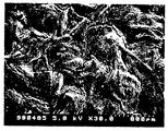
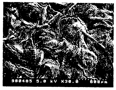
次いで、この撥水処理シートの片面に、フッ素樹脂(ポリテトラフロロエチレン)とカーボン微粒子(アセチレンブラック、平均粒径0.05μm)を質量比で85/15で混合した水分散スラリーを塗布した後、常温から昇温度勾配5℃/分にて120℃まで昇温させ到達後、10分間乾燥、熱処理して薄膜を設けた炭素繊維シートを得た。このシートの電子顕微鏡写真を図1に示す。
【0049】
得られた、炭素繊維シートは厚さ330μm、薄膜厚さ42μm、薄膜中の溝最大幅5.1μm、溝の占有面積率7.5%、総目付135g/m2 であった。
【0050】
このシートの電池性能を測定した結果、高電流密度(1.6A/m2 )での起電圧は0.85Voltと高い値が得られた。
【0051】
[実施例2〜3及び比較例1〜3]
薄膜の塗設条件を表1に示すものとした以外は実施例1と同様に薄膜を設けた炭素繊維シートを得た。得られたシートの電池性能測定結果を表1に示す。
【0052】
【表1】
【0053】
表1に示した結果から明らかなように、実施例1〜3のガス拡散電極材はいずれも電池性能に優れたものであった。一方、比較例1〜3のガス拡散電極材はいずれも電池性能に劣るものであった。
【0054】
[実施例4、5]
基材の炭素繊維シートとして表2に示すものを用い、薄膜の塗設条件を表2に示すものとした以外は実施例1と同様に薄膜を設けた炭素繊維シートを得た。得られたシートの電池性能測定結果を表2に示す。
【0055】
【表2】
【0056】
表2に示した結果から明らかなように、実施例4,5のガス拡散電極材はいずれも電池性能に優れたものであった。
【0057】
【発明の効果】
本発明の燃料電池用ガス拡散電極によれば、高電流密度側の電池特性を改善でき、電池特性に優れる燃料電用ガス拡散電極材を提供することができる。
【図面の簡単な説明】
【図1】本発明の燃料電用ガス拡散電極材表面の薄膜に溝が生じている状態を示す、図面代用走査型電子顕微鏡(SEM)写真である。[0001]
TECHNICAL FIELD OF THE INVENTION
The present invention relates to a gas diffusion electrode for a fuel cell, and more particularly, to a polymer electrolyte type gas diffusion electrode for a fuel cell having excellent cell characteristics.
[0002]
[Prior art]
As a base material for a polymer electrolyte type gas diffusion electrode material for a fuel cell, application of a sheet material such as a woven or nonwoven fabric of carbon fiber has been promoted. The basic principle of power generation by a fuel cell is to convert energy generated when hydrogen reacts with oxygen in the air to produce water into electric energy. For this reason, usually, a water-repellent treatment is performed on the gas diffusion electrode material base material as a technique for improving the mobility of generated water. Further, in order to prevent the electrolyte membrane from being damaged and to improve the flatness of the surface, the surface (one surface) of the base sheet is treated with carbon fine particles and a fluororesin.
[0003]
In addition, the following properties are required as gas diffusion electrode materials.
(I) Good acid resistance (because an acidic atmosphere occurs when protons are generated by the reaction between hydrogen and oxygen at 80 to 100 ° C.).
(Ii) The thickness of the electrode material is thinner (to make the battery more compact).
(Iii) Good gas permeability for hydrogen and the like (to improve battery performance on the high current density side).
[0004]
Carbon fiber spun yarn woven fabrics and nonwoven fabrics have excellent conductivity and acid resistance, and it is easy to prepare thin sheet-shaped electrode materials. It is formed in a film on one side. The state of the formed film affects gas permeability (diffusion). If the gas permeability is poor, battery performance will be reduced.
[0005]
In response to the above request, the following has been proposed.
[0006]
(A) Carbon paper as a current collector is treated with a fluororesin to impart water repellency to the carbon paper (Patent Documents 1 and 2).
[0007]
(A) A method of coating a mixture of carbon fine particles carrying an electrode catalyst and a polytetrafluoroethylene dispersion on the surface of a carbon cloth or carbon paper and bonding them by pressure bonding to improve a method of bonding a film to a substrate (Patent Document 3).
[0008]
(C) Using a gas diffusion layer obtained by subjecting a carbon paper made of carbon fiber made of polyacrylonitrile to water-repellent treatment with a fluororesin (Patent Document 4). This proposal improves gas diffusivity by increasing the pore diameter.
[0009]
However, in these proposals, there is a problem that the battery performance (cell voltage) on the high current density side does not increase, and improvement thereof is desired.
[0010]
[Patent Document 1]
JP-A-7-130373 (Claims)
[Patent Document 2]
JP-A-7-130374 (Claims)
[Patent Document 3]
JP-A-6-020710 (Claims)
[Patent Document 4]
JP-A-6-295728 (Claims)
[0011]
[Problems to be solved by the invention]
The present invention solves the above problems and improves gas permeability, thereby improving the battery characteristics on the high current density side. As a result, the present invention provides a gas diffusion electrode material for fuel cells that is excellent in overall battery characteristics. That is the task.
[0012]
[Means for Solving the Problems]
The present inventor can improve gas permeability by forming specific grooves (cracks) in a thin film mainly composed of a mixture of carbon fine particles and a fluororesin provided on one surface of a carbon fiber sheet substrate, thereby improving gas permeability. The inventors have found that the battery characteristics on the density side can be improved, and have reached the present invention.
[0013]
The present invention that achieves the above object is as described below.
[0014]
[1] A gas diffusion electrode for a fuel cell, comprising: a carbon fiber sheet; and a thin film mainly composed of a mixture of carbon fine particles and a fluororesin formed on one surface of the carbon fiber sheet, wherein the thin film is formed of both thin films. A gas diffusion electrode for a fuel cell, comprising a groove connecting the surfaces, and wherein the occupied area ratio of the groove to the thin film surface is 3 to 15%.
[0015]
[2] The thickness of the carbon fiber sheet (T1) is 100 to 450 μm, the average thickness (T2) of the thin film is 20 to 80 μm, and the maximum width (W2) of the groove is 0.05 to 20 μm. Gas diffusion electrode for fuel cells.
[0016]
[3] The gas diffusion electrode for a fuel cell according to [1], wherein the carbon fiber sheet has been subjected to a water-repellent treatment.
[0017]
BEST MODE FOR CARRYING OUT THE INVENTION
The gas diffusion electrode for a fuel cell of the present invention is formed on one surface of a carbon fiber sheet as a base material by forming a thin film having a mixture of carbon fine particles and a fluororesin as a main component and having a groove having a specific occupation area ratio. It is characterized by having. The groove connects both surfaces of the thin film.
[0018]
In the present invention, the carbon fiber sheet used as the base material has a sheet shape composed of carbon fibers, and examples thereof include a woven fabric, a nonwoven fabric, and a paper of spun carbon fiber yarn.
[0019]
In the present invention, the thickness (T1) of the carbon fiber sheet is preferably 100 μm to 450 μm. If this T1 is less than 100 μm, the strength of the carbon fiber sheet is reduced, and the carbon fiber is likely to be cut or the sheet is torn during water repellent treatment or carbon treatment. On the other hand, when T1 exceeds 450 μm, gas permeability may decrease, and battery performance may decrease. The thickness of the carbon fiber sheet can be adjusted by adjusting the basis weight and pressure treatment in the thickness direction of the raw material sheet.
[0020]
The carbon fiber used for the carbon fiber sheet is not particularly limited, but a PAN-based carbon fiber using polyacrylonitrile (PAN) fiber as a raw material of the carbon fiber is preferable. In addition to PAN, carbon fibers obtained using pitch, phenol, rayon, or the like as a raw material may be used. The diameter of the carbon fiber used for the carbon fiber sheet substrate is not particularly limited, but is preferably 8.0 to 15.0 μm.
[0021]
In the present invention, a thin film having a mixture of carbon fine particles and a fluororesin as a main component and having grooves on at least a part thereof is provided on one sheet surface of the carbon fiber sheet.
[0022]
The components constituting the thin film are preferably only carbon fine particles and a fluororesin, but components other than the carbon fine particles and the fluororesin (for example, a catalyst such as activated carbon and platinum) are present in an amount of less than 5% by mass. Is also good. The ratio of the carbon fine particles to the total amount of the carbon fine particles and the fluororesin in the thin film is preferably 20 to 60% by mass. If the proportion of the carbon fine particles is less than 20% by mass, the surface smoothness, conductivity, and catalyst characteristics of the thin film are reduced, and the battery performance may be reduced. On the other hand, when the ratio of the carbon fine particles exceeds 60% by mass, the groove width and the groove occupation area ratio on the surface of the thin film are increased, and it is difficult to control the groove characteristics to a required range.
[0023]
The type of carbon fine particles constituting the thin film is not particularly limited, but for example, a graphitized carbon material using a petroleum-based or coal-based pitch, PAN, phenol, rayon-based or the like as a carbon material, or the like can be used. Among these, conductive carbon fine particles having a high purity of graphite are particularly preferable. For example, commercially available acetylene black, carbon black, finely divided carbon fibers, carbon whiskers, carbon nanotubes, and the like are particularly preferable examples.
[0024]
The particle diameter of the carbon fine particles in the present invention is preferably 1.0 μm or less, and if the dispersibility is good, a finer particle is more preferable. If the particle diameter of the carbon fine particles exceeds 1.0 μm, the groove width on the surface of the thin film becomes too large, and it becomes difficult to control the groove occupation area ratio within the range of the present invention, which is not preferable.
[0025]
This thin film is formed by applying, for example, a dispersion of water or an organic solvent mainly containing a mixture of carbon fine particles and a fluororesin to one sheet surface of a carbon fiber sheet, and then performing a heat treatment (for example, at a temperature of 100 to 350 ° C.). Below, it can be provided by evaporating water or an organic solvent by, for example, heat treatment at a specific temperature gradient in which a groove is formed.
[0026]
In the present invention, the fluororesin used for the thin film containing carbon fine particles and the fluororesin as main components is not particularly limited. For example, polytetrafluoroethylene (PTFE), tetrafluoroethylene-hexafluoropropylene copolymer (FEP), tetrafluoroethylene Fluororesins such as ethylene-perfluoroalkyl vinyl ether copolymer (PFA) are preferred in terms of heat resistance and acid resistance.
[0027]
In the present invention, the occupied area ratio of the groove to the thin film surface (the ratio of the total area of the groove to a predetermined area of the carbon fiber sheet provided with the thin film) needs to be 3 to 15%. If the occupied area ratio of the groove to the thin film surface is less than 3%, the effect of improving gas permeability is insufficient, and the battery characteristics on the high current density side cannot be improved. When the occupied area ratio of the groove to the thin film surface exceeds 15%, the reactivity between hydrogen and oxygen decreases, and as a result, the battery performance decreases. For the above reason, the occupied area ratio of the groove to the thin film surface is preferably 5 to 12%.
[0028]
The occupied area ratio of the groove to the surface of the thin film can be adjusted, for example, as follows. That is, after applying an aqueous dispersion containing fine carbon particles and a fluororesin to the surface of the carbon fiber sheet, and then performing a heat treatment to form a thin film, by adjusting the temperature rise temperature gradient of the heat treatment, or in the aqueous dispersion. By adjusting the content of the carbon fine particles.
[0029]
In the above heat treatment, the temperature rise temperature gradient is preferably 0.5 to 15 ° C./min, the maximum temperature is preferably 100 to 350 ° C., and the treatment time is preferably 5 to 30 minutes. The content of the fine particles is preferably in the range of 10 to 40% by mass. If the conditions of the heat treatment are in the above range, the groove occupation area ratio and the groove width on the thin film surface can be controlled to the essential range and the preferable range of the present invention.
[0030]
In addition, as a method of forming grooves on the surface of the thin film in the present invention, in addition to the above, the entire carbon fiber sheet provided with the thin film of carbon fine particles and the fluororesin is heated to 100 to 350 ° C. A method of rapidly cooling to a temperature of not more than ° C. and generating fine cracks due to rapid shrinkage of the thin film can be mentioned. In addition, a method of applying an aqueous dispersion containing carbon fine particles and a fluororesin to the surface of a carbon fiber sheet in a pattern in which grooves can be formed by applying screen printing or gravure printing technology, and then performing a heat treatment, or A method of applying an aqueous dispersion containing a thermoplastic resin soluble in a solvent in addition to carbon fine particles and a fluororesin on the surface of the sheet, forming a thin film by heat treatment, and then dissolving and removing the thermoplastic resin with a solvent. May be used.
[0031]
In the present invention, the average thickness (T2) of the thin film provided on one side of the carbon fiber sheet is preferably 20 μm to 80 μm. If T2 is less than 20 μm, the strength of the thin film may be insufficient. Alternatively, the maximum width of the groove may increase and the desired width may not be obtained. On the other hand, when T2 exceeds 80 μm, gas permeability may decrease.
[0032]
Adjustment of the average thickness of the thin film is performed by adjusting the coating amount and the viscosity of the mixture solution of the mixture solution of the carbon fine particles and the fluororesin per carbon fiber sheet base material, or by selecting the coating method of the mixture solution. be able to.
[0033]
In the present invention, the maximum width (W2) of the groove existing on one surface of the carbon fiber sheet is preferably 0.05 μm to 20 μm. If W2 is less than 0.05 μm, gas permeability may decrease, and battery performance may decrease. On the other hand, if W2 exceeds 20 μm, the electrolyte membrane is likely to be damaged, and as a result, battery performance may be reduced.
[0034]
The shape of the groove on the surface of the thin film is not particularly limited, and any shape such as a linear shape, a curved shape, and an irregular shape can be adopted. The length of the groove is not particularly limited, but is preferably 0.5 μm to 100 μm.
[0035]
The adjustment of the maximum width (W2) of the groove can be mainly performed by a temperature rising temperature gradient in the heat treatment performed after the application of the mixed liquid, the heat treatment temperature, the heat treatment time, the content of carbon fine particles, and the like.
[0036]
In addition, the carbon fiber sheet used for the base material in the present invention is preferably one subjected to a water-repellent treatment. This water-repellent treatment can be performed, for example, by the following method. That is, the carbon fiber sheet can be immersed in an aqueous solution or aqueous dispersion of a fluorinated resin, a predetermined fluorinated resin can be attached thereto, and then a smelting treatment can be performed in air at 300 to 350 ° C. to impart water repellency. This water-repellent treatment is preferably performed before forming the thin film.
[0037]
The fluororesin used for the water-repellent treatment is not particularly limited. For example, polytetrafluoroethylene (PTFE), tetrafluoroethylene-hexafluoropropylene copolymer (FEP), tetrafluoroethylene-perfluoroalkylvinyl ether copolymer (PFA) Fluororesins are preferred in terms of heat resistance and acid resistance.
[0038]
In the water repellent treatment, an aqueous dispersion having a fluororesin concentration of 0.3 to 5.0% by mass can be preferably used. Further, the amount of fluororesin adhered to the water-repellent carbon fiber sheet is preferably 0.5 to 10.0% by mass. If the amount of the attached fluororesin is 0.5% by mass or less, the water repellency may be reduced. If the amount of the attached fluororesin exceeds 10.0% by mass, the adhesion between the thin film and the carbon fiber sheet is reduced in the subsequent step of providing a thin film containing a mixture of carbon fine particles and the fluororesin as a main component. Peeling easily occurs.
[0039]
In addition, as a condition of the water-repellent treatment, a temperature of 250 to 400 ° C. (a temperature at which the fluororesin is semi-molten) is required. The processing time is, for example, 3 to 30 minutes.
[0040]
【Example】
Hereinafter, the present invention will be described more specifically with reference to examples. In the examples and comparative examples, various test methods were as follows.
[0041]
(1) Carbon fiber sheet thickness (T1)
The thickness (μm) when 200 g (2.8 kPa) was applied to the carbon fiber sheet provided with the thin film with a disc-shaped pressure plate having a diameter of 30 mm was measured.
[0042]
(2) Average thickness of thin film (T2)
The carbon fiber sheet provided with the thin film was cut into a 50 mm square, the thickness was measured (10 measurement points) from this cross-sectional photograph (magnification: 50 times), and the average value (μm) was calculated.
[0043]
(3) Maximum width of groove (W2)
The maximum width of the groove was measured from an enlarged photograph of the thin film surface of one side of the 50 mm square sheet (1,000 times magnification) of the carbon fiber sheet provided with the thin film.
[0044]
(4) Groove occupation area ratio (S2)
Image analysis of a 50 mm square single-sided thin film surface of the thin film provided with the thin film (magnification: 1,000 times), the area of the thin film groove was measured, and the area occupied by the groove was calculated from the value obtained by dividing the area of the thin film groove (%). I asked.
[0045]
(5) The mass per unit area was calculated from the dimensions of the carbon fiber sheet provided with the basis weight thin film of the carbon fiber sheet and the dry mass at 120 ° C.
[0046]
(6) Battery performance evaluation method A carbon fiber sheet provided with a thin film was cut into a 50 mm square, and 0.2 mg / cm 2 of a catalyst (Pt-Rt) was loaded on the carbon fiber sheet to support the polymer electrolyte membrane (Nafion 117). Then, the above-mentioned electrode material cut into a square of 50 mm was joined to form a cell, and the cell voltage was measured at a temperature of 80 ° C. and a current density of 1.6 A / cm 2 .
[0047]
[Example 1]
A polyacrylonitrile-based carbon fiber spun yarn fabric (plain weave, thickness 350 μm, basis weight 115 g / m 2 , fiber diameter 11.1 μm) was immersed in an aqueous dispersion (1% by mass) of a fluororesin (polytetrafluoroethylene). Thereafter, the sheet was transferred into the air and heat-treated at 350 ° C. for 5 minutes to obtain a water-repellent sheet having a fluorine resin adhesion amount of 1.5% by mass.
[0048]
Then, an aqueous dispersion slurry in which a fluororesin (polytetrafluoroethylene) and carbon fine particles (acetylene black, average particle diameter: 0.05 μm) are mixed at a mass ratio of 85/15 is applied to one surface of the water-repellent treated sheet. Then, the temperature was raised from normal temperature to 120 ° C. at a temperature rising rate of 5 ° C./min, and then dried and heat-treated for 10 minutes to obtain a carbon fiber sheet provided with a thin film. An electron micrograph of this sheet is shown in FIG.
[0049]
The obtained carbon fiber sheet had a thickness of 330 μm, a thin film thickness of 42 μm, a maximum width of the groove in the thin film of 5.1 μm, an occupied area ratio of the groove of 7.5%, and a total basis weight of 135 g / m 2 .
[0050]
As a result of measuring the battery performance of this sheet, the electromotive voltage at a high current density (1.6 A / m 2 ) was as high as 0.85 Volt.
[0051]
[Examples 2 to 3 and Comparative Examples 1 to 3]
A carbon fiber sheet provided with a thin film was obtained in the same manner as in Example 1 except that the conditions for applying the thin film were as shown in Table 1. Table 1 shows the results of measuring the battery performance of the obtained sheet.
[0052]
[Table 1]
[0053]
As is clear from the results shown in Table 1, the gas diffusion electrode materials of Examples 1 to 3 were all excellent in battery performance. On the other hand, the gas diffusion electrode materials of Comparative Examples 1 to 3 were all inferior in battery performance.
[0054]
[Examples 4 and 5]
A carbon fiber sheet provided with a thin film was obtained in the same manner as in Example 1 except that the one shown in Table 2 was used as the carbon fiber sheet of the base material, and the conditions for applying the thin film were changed to those shown in Table 2. Table 2 shows the results of measuring the battery performance of the obtained sheet.
[0055]
[Table 2]
[0056]
As is clear from the results shown in Table 2, the gas diffusion electrode materials of Examples 4 and 5 were all excellent in battery performance.
[0057]
【The invention's effect】
ADVANTAGE OF THE INVENTION According to the gas diffusion electrode for fuel cells of the present invention, the cell characteristics on the high current density side can be improved, and a gas diffusion electrode material for fuel cells having excellent cell characteristics can be provided.
[Brief description of the drawings]
FIG. 1 is a scanning electron microscope (SEM) photograph as a substitute of a drawing, showing a state in which a groove is formed in a thin film on the surface of a fuel-diffusion gas diffusion electrode material of the present invention.