JP2004235934A - Calibration processing device, calibration processing method, and computer program - Google Patents
Calibration processing device, calibration processing method, and computer program Download PDFInfo
- Publication number
- JP2004235934A JP2004235934A JP2003021605A JP2003021605A JP2004235934A JP 2004235934 A JP2004235934 A JP 2004235934A JP 2003021605 A JP2003021605 A JP 2003021605A JP 2003021605 A JP2003021605 A JP 2003021605A JP 2004235934 A JP2004235934 A JP 2004235934A
- Authority
- JP
- Japan
- Prior art keywords
- feature point
- sphere
- matrix
- image
- camera
- Prior art date
- Legal status (The legal status is an assumption and is not a legal conclusion. Google has not performed a legal analysis and makes no representation as to the accuracy of the status listed.)
- Granted
Links
Images





Landscapes
- Image Processing (AREA)
- Testing, Inspecting, Measuring Of Stereoscopic Televisions And Televisions (AREA)
- Studio Devices (AREA)
- Image Analysis (AREA)
- Length Measuring Devices By Optical Means (AREA)
Abstract
【課題】多視点画像撮影システムにおけるキャリブレーションを高精度にかつ効率的に実行する装置および方法を提供する。
【解決手段】キャリブレーション処理対象となるカメラにより、発光球体を異なる方向から撮影し、撮影画像フレームから球体中心位置を特徴点として抽出し、抽出した球体中心位置に基づく特徴点対応付けを実行し、特徴点対応付けデータに基づいてファンダメンタル(Fundamental)行列の算出を実行する。照明環境等に影響しにくい発光球体をキャリブレーション治具として用い、球体の中心位置をリアルタイムに検出し対応付けしながらF行列を推定し、推定されたF行列と対応点との誤差や位置関係などを評価することによって、必要となる対応点の数や三次元空間上に置くべき球体位置を指示し、より高精度なF行列を効率的に算出することが可能となる。
【選択図】 図11An apparatus and method for performing calibration in a multi-viewpoint image capturing system with high accuracy and efficiency.
A luminous sphere is photographed from different directions by a camera to be subjected to calibration processing, a sphere center position is extracted as a feature point from a photographed image frame, and feature point association based on the extracted sphere center position is executed. And a calculation of a fundamental matrix based on the feature point association data. Using a luminous sphere that does not easily affect the lighting environment, etc., as a calibration jig, the F matrix is estimated while detecting and associating the center position of the sphere in real time, and the error and positional relationship between the estimated F matrix and the corresponding point. By evaluating such factors, the number of necessary corresponding points and the position of a sphere to be placed in a three-dimensional space are indicated, and a more accurate F matrix can be efficiently calculated.
[Selection diagram] FIG.
Description
【0001】
【発明の属する技術分野】
本発明は、キャリブレーション処理装置、およびキャリブレーション処理方法、並びにコンピュータ・プログラムに関する。さらに詳細には、異なる位置に配置した複数のカメラで被写体を撮影して多視点画像を生成する多視点画像撮影カメラ間の調整、または多視点画像撮影カメラの取得画像の補正処理に適用するパラメータ算出処理を行うキャリブレーション処理装置、およびキャリブレーション処理方法、並びにコンピュータ・プログラムに関する。
【0002】
【従来の技術】
近年、パノラマ、全天球画像など、視点を様々に移動可能とした画像データの利用が盛んになりつつある。例えば、DVD、CD等の記憶媒体に複数の視点位置、視線方向からある被写体を撮影した画像を蓄積し、蓄積画像をCRT、液晶表示装置等に表示する際に、ユーザがコントローラの操作によって、自由な位置に視点を移動させて、被写体の像を観察するシステムが実現されている。また、インターネット等の通信システムを介して複数の視点位置、視線方向からある被写体を撮影した画像を配信し、ユーザがPC等のマウス操作により、好みの視点位置、視線方向からの画像をディスプレイに表示するシステム等が構築されている。
【0003】
コンピュータの処理能力の向上や多様な映像メディア再生機器の発展に伴って、以前困難とされた膨大なポリゴンデータや映像データ(コンテンツ)の処理が可能となり、視点の異なる複数台カメラで撮影された実世界(対象)の映像データをコンピュータや映像機器等により処理し、ユーザの要望に応じた任意視点の映像を実時間に生成し提示することができるようになってきている。
【0004】
コンピュータ上の処理によって複数の視点で撮影された画像から任意視点映像を生成し、提示するためには、(1)全てのカメラが同一の領域(注目対象)を見えていること、(2)各カメラ間の位置関係等が得られることが必要である。
【0005】
同じ対象を注目している視点の異なる複数カメラで撮影した多視点映像に基づいて、実写カメラの間の任意位置の仮想カメラで撮影した仮想視点映像を画像処理によって生成することが可能であるが、高精度な仮想視点映像を生成するには実写カメラ間の位置関係を正確に求めることが必要となる。実写カメラ間の位置関係を示すパラメータとしてジオメトリ・パラメータ(Geometry Parameters)がある。ジオメトリ・パラメータは、行列式によって表現され、これをファンダメンタル(Fundamental)行列またはF行列と呼ぶ。
【0006】
実写カメラ間の位置関係を表すファンダメンタル(Fundamental)行列を求める方法は、これまでにも数多く提案されている。例えば、幾つかの(隣接)カメラによって、三次元空間にあるチェッカパターンを同時に観測し、チェッカパターン画像上の特徴点(例えば、白黒パターンの交差点位置)を抽出し、それらの特徴点の対応付けを行うことによって、ファンダメンタル(Fundamental)行列を推定する方法が知られている(例えば非特許文献1)。
【0007】
しかしながら、(1)実際の撮影現場では、照明光の影響(例えば、反射光)等によって、撮影したチェッカパターン画像から必ずしも対応点を精度よく求めることができないため、高精度なファンダメンタル行列(以下、F行列と表現する)を推定することが容易ではない。(2)また、視点の異なる多数カメラで同一のチェッカパターンプレートを観測する場合、観測カメラはチェッカパターンプレートに正対していない場合が多く、そのため、観測されたチェッカパターン画像上のパターン変形によって、チェッカパターン画像における特徴点位置を精度よく検出することが容易ではないという問題がある。
【0008】
(3)さらに、多数のカメラを同じ対象(被写体)を囲むように配置しようとした場合、撮影されたチェッカパターンが変形するだけでなく、平面状のチェッカパターンを用いると、チェッカパターンを360度周囲取り囲むよう配置しても全てのカメラが同じチェッカパターンを同時に撮影することができない。その際、多視点カメラを幾つかのグループに分けて、チェッカパターンを複数のカメラで複数回に分けて撮影することが必要となり、多くの労力や時間等を費やすことになる。(4)さらに、カメラキャリブレーションを行う際、F行列を推定するためのチェッカ画像パターンが十分に収録できたか、またそれらのチェッカパターンの空間位置が適切であるかどうかを判断する処理についての明確な基準がなく、結果的に算出されるF行列の精度が保証されないという問題がある。
【0009】
【非特許文献1】
R.Y.Tsai: An Efficient and Accurate Camera Calibration Technique for 3D Machine Vision, Proceedings of IEEE Conference on Computer Vision and Pattern Recognition, Miami Beach, FL, pp.364−374,(1986)
【0010】
【発明が解決しようとする課題】
本発明は、上述の問題点に鑑みてなされたものであり、多視点映像撮影システムを構成する実写カメラ間の位置関係を示すパラメータであるジオメトリ・パラメータ(Geometry Parameters)の算出を高精度に行なうことを可能とし、高速かつ高精度なカメラキャリブレーションを実現するカメラキャリブレーション装置、およびカメラキャリブレーション方法、並びにコンピュータ・プログラムを提供することを目的とする。
【0011】
本発明は、照明環境等に影響しにくい発光球体をキャリブレーション治具として用い、球体の中心位置をリアルタイムに検出し対応付けしながらF行列を推定し、推定されたF行列と対応点との誤差や位置関係などを評価することによって、必要となる対応点の数や三次元空間上に置くべき球体位置を指示し、より高精度なF行列を自動的に推定するものである。
【0012】
球体の形状はカメラ観測視点位置によらないため、様々な視点位置で全てのカメラによって観測可能となる。また、同期機能を備えた多視点映像撮影システムによって球体画像を観測撮影し、各パソコン上のメモリやハードディスクなどの記録媒体に収録しながらカメラキャリブレーションを行うことが可能である。そして、各パソコン上の画像処理手法によって、各フレーム画像における球体中心の座標位置(特徴点)を抽出し、抽出した特徴点を用いた画像間の対応付けによってファンダメンタル(Fundamental)行列を推定する。さらに、推定されたF行列の精度評価を実行して、対応点の数や対応点の適切な位置、つまり、球体の空間位置を自動的に提示し、高速かつ高精度なカメラ間パラメータの自動的推定を実現する装置および方法を提供する。
【0013】
【課題を解決するための手段】
本発明の第1の側面は、
多視点画像撮影カメラ間の調整、または多視点画像撮影カメラによる取得画像の補正処理に適用するパラメータ算出処理を実行するキャリブレーション処理装置であり、
移動する球体を異なる視点方向から撮影した複数カメラの映像データを入力する画像入力部と、
前記画像入力部において入力する複数カメラの映像データを構成する複数の撮影画像フレームから球体中心位置を特徴点として抽出する処理を実行する特徴点抽出部と、
各カメラの対応フレームにおける特徴点として前記特徴点抽出部において抽出された球体中心位置の対応付け処理を実行する対応付け処理部と、
前記対応付け処理部において対応付けのなされた特徴点対応データに基づいてキャリブレーションパラメータとしてのファンダメンタル(Fundamental)行列を算出するF行列算出部と、
を有することを特徴とするキャリブレーション処理装置にある。
【0014】
さらに、本発明のキャリブレーション処理装置の一実施態様において、前記球体は、発光球体であり、前記特徴点抽出部は、フレームに撮影された球体のエッジ情報に基づいて球体中心位置を算出する処理を実行する構成であることを特徴とする。
【0015】
さらに、本発明のキャリブレーション処理装置の一実施態様において、前記F行列算出部は、算出したF行列に基づくエピポーララインを設定し、設定したエピポーララインと、特徴点に対応する球体中心位置との距離を個別にまたは平均距離として算出し、該算出距離が予め定めた閾値より大である場合は新たな特徴点を含む特徴点対応データに基づいてF行列の再算出処理を実行する構成であることを特徴とする。
【0016】
さらに、本発明のキャリブレーション処理装置の一実施態様において、前記F行列算出部は、撮影画像フレーム内における球体中心位置、すなわち特徴点の分布状況判定処理を実行し、特徴点偏在が確認された場合、該偏在を解消する位置に追加設定した特徴点を含む特徴点対応データに基づくF行列再算出処理を実行する構成であることを特徴とする。
【0017】
さらに、本発明のキャリブレーション処理装置の一実施態様において、前記特徴点抽出部は、撮影フレーム内に球体全体のエッジが存在する場合にのみ、該エッジ情報に基づく中心位置算出処理を実行する構成であることを特徴とする。
【0018】
さらに、本発明のキャリブレーション処理装置の一実施態様において、前記特徴点抽出部は、前記F行列の9個の要素の比率を算出するために必要となる少なくとも8点の球体中心位置データを各カメラの複数の撮影画像フレームから取得し、前記対応付け処理部は、前記特徴点抽出部において抽出された8点以上の球体中心位置の対応付け処理を実行し、前記F行列算出部は、対応付けのなされた8以上の特徴点対応データに基づいてキャリブレーションパラメータとしてのファンダメンタル(Fundamental)行列の要素値算出を実行する構成であることを特徴とする。
【0019】
さらに、本発明の第2の側面は、
多視点画像撮影カメラ間の調整、または多視点画像撮影カメラの取得画像の補正処理に適用するパラメータ算出処理を実行するキャリブレーション処理方法であり、
移動する球体を異なる視点方向から撮影した複数カメラの映像データを入力する画像入力ステップと、
前記画像入力ステップにおいて入力する複数カメラの映像データを構成する複数の撮影画像フレームから球体中心位置を特徴点として抽出する特徴点抽出ステップと、
前記特徴点抽出ステップにおいて抽出された球体中心位置に基づいて特徴点対応付け処理を実行する対応付け処理ステップと、
前記対応付け処理ステップにおいて対応付けのなされた特徴点対応データに基づいてキャリブレーションパラメータとしてのファンダメンタル(Fundamental)行列を算出するF行列算出ステップと、
を有することを特徴とするキャリブレーション処理方法にある。
【0020】
さらに、本発明のキャリブレーション処理方法の一実施態様において、前記球体は、発光球体であり、前記特徴点抽出ステップは、フレームに撮影された球体のエッジ情報に基づいて球体中心位置の算出処理を実行することを特徴とする。
【0021】
さらに、本発明のキャリブレーション処理方法の一実施態様において、前記F行列算出ステップは、算出したF行列に基づくエピポーララインを設定し、設定したエピポーララインと前記特徴点としての球体中心位置との距離を個別にまたは平均距離として算出し、該算出距離が予め定めた閾値より大である場合は新たな特徴点を含む特徴点対応データに基づくF行列再算出処理を実行することを特徴とする。
【0022】
さらに、本発明のキャリブレーション処理方法の一実施態様において、前記F行列算出ステップは、撮影画像フレーム内における球体中心位置、すなわち特徴点の分布状況判定処理を実行し、特徴点偏在が確認された場合、該偏在を解消する位置に追加設定した追加特徴点を含む特徴点対応データに基づくF行列再算出処理を実行することを特徴とする。
【0023】
さらに、本発明のキャリブレーション処理方法の一実施態様において、前記特徴点抽出ステップは、撮影フレーム内に球体全体のエッジが存在する場合にのみ、該エッジ情報に基づく中心位置算出処理を実行することを特徴とする。
【0024】
さらに、本発明のキャリブレーション処理方法の一実施態様において、前記特徴点抽出ステップは、前記F行列の9個の要素の比率を算出するために必要となる少なくとも8点の球体中心位置データを各カメラの複数の撮影画像フレームから取得し、前記対応付け処理ステップは、前記特徴点抽出ステップにおいて抽出された8点以上の球体中心位置の対応付け処理を実行し、前記F行列算出ステップは、対応付けのなされた8以上の特徴点対応データに基づいてキャリブレーションパラメータとしてのファンダメンタル(Fundamental)行列を構成する要素値算出を実行することを特徴とする。
【0025】
さらに、本発明の第3の側面は、
多視点画像撮影カメラ間の調整、または多視点画像撮影カメラの取得画像の補正処理に適用するパラメータ算出処理を実行するコンピュータ・プログラムであって、
移動する球体を異なる視点方向から撮影した複数カメラの映像データを入力する画像入力ステップと、
前記画像入力ステップにおいて入力する複数カメラの映像データを構成する複数の撮影画像フレームから球体中心位置を特徴点として抽出する特徴点抽出ステップと、
前記特徴点抽出ステップにおいて抽出された球体中心位置の対応付け処理を実行する対応付け処理ステップと、
前記対応付け処理ステップにおいて対応付けのなされた特徴点対応データに基づいてキャリブレーションパラメータとしてのファンダメンタル(Fundamental)行列を算出するF行列算出ステップと、
を具備することを特徴とするコンピュータ・プログラムにある。
【0026】
【作用】
本発明の構成によれば、多視点画像撮影カメラ間の調整、または多視点画像撮影カメラによる取得画像の補正処理に適用するパラメータ算出処理を実行するキャリブレーション処理において、発光球体を各カメラにより撮影する構成としたので、照明環境が不安定な撮影現場等でも球体検出と球体中心位置の取得を容易に行うことができ、球体中心位置を特徴点として対応付け処理を実行することで高精度なF行列の算出が可能となる。すなわち、多視点映像撮影システムを構成する実写カメラ間の位置関係を示すパラメータであるジオメトリ・パラメータ(Geometry Parameters)としてのファンダメンタル(Fundamental)行列の算出を高精度に行なうことが可能となり、高速かつ高精度なキャリブレーションが可能となる。
【0027】
さらに、本発明の構成によれば、発光球体をキャリブレーション治具として用い、球体の中心位置をリアルタイムに検出し対応付けしながらF行列を推定し、推定されたF行列と対応点との誤差や位置関係などを評価することによって、必要となる対応点の数や三次元空間上に置くべき球体位置を指示し、より高精度なF行列を効率的に算出することが可能となる。
【0028】
さらに、本発明の構成によれば、同期機能を備えた多視点映像撮影システムによって球体画像を観測撮影し、各パソコン上のメモリやハードディスクなどの記録媒体に収録しながらカメラキャリブレーションを行うことが可能であり、各パソコン上の画像処理手法によって、各フレーム画像における球体中心の座標位置(特徴点)抽出、抽出特徴点を用いた画像間の対応付けによるファンダメンタル(Fundamental)行列の推定、推定F行列の精度評価、対応点の数や対応点の適切な位置の判定、提示等を、例えばPC上で実行可能であり、高速かつ高精度なキャリブレーション処理を、PC等、簡易なシステムにおいて実行することが可能となる。
【0029】
なお、本発明のコンピュータ・プログラムは、例えば、様々なプログラム・コードを実行可能な汎用コンピュータ・システムに対して、コンピュータ可読な形式で提供する記憶媒体、通信媒体、例えば、CDやFD、MOなどの記憶媒体、あるいは、ネットワークなどの通信媒体によって提供可能なコンピュータ・プログラムである。このようなプログラムをコンピュータ可読な形式で提供することにより、コンピュータ・システム上でプログラムに応じた処理が実現される。
【0030】
本発明のさらに他の目的、特徴や利点は、後述する本発明の実施例や添付する図面に基づく、より詳細な説明によって明らかになるであろう。なお、本明細書においてシステムとは、複数の装置の論理的集合構成であり、各構成の装置が同一筐体内にあるものには限らない。
【0031】
【発明の実施の形態】
以下、本発明のカメラキャリブレーション装置、およびカメラキャリブレーション方法、並びにコンピュータ・プログラムについて、図面を参照しながら詳細に説明する。
【0032】
まず、図1を参照して多視点カメラ撮影処理及び多視点カメラで撮影した実写映像を用いて仮想視点映像を生成する処理について説明する。被写体100を、被写体100周囲に配置した複数のカメラで撮影する。各カメラは、異なる視点からの被写体100の画像を撮影する。実写画像は、配置するカメラ数に応じて取得される。しかし、各カメラ間の実写画像は取得できない。従って各カメラ間の画像、すなわち仮想視点の画像は、実写画像に基づく画像処理によって生成する。
【0033】
例えばカメラA101と、カメラB102との間にカメラが配置されていない場合、カメラA101と、カメラB102との間の画像は、これらのカメラの2つの実写画像111,112に基づいて生成する。これは、実際には撮影されていない画像を生成する処理、いわゆるビューインターポレーション処理によって生成することができる。
【0034】
ビューインターポレーションとは、複数のカメラからの画像から、実際のカメラのない視点から見える画像を生成する技術である。このビューインターポレーションについては、たとえば[S. M. Seitz and C. R. Dyer, ”View Morphing,”Proc. SIGGRAPH 96, ACM, 1996pp.21−30.]に記載されている。ビューインターポレーションによれば、複数のカメラに基づく実際の取得画像に基づいて、カメラのない視点の画像の生成が可能となる。
【0035】
例えば、カメラA101とカメラB102の間であたかも仮想カメラ113で撮影したような仮想視点カメラ画像121を生成するためには、カメラA101とカメラB102の特性の違いや相対的な位置関係を求め、これらの情報としてのパラメータに基づいて仮想視点画像の生成における各種補正を行なうことが必要になる。つまり、実写画像を撮影しているカメラの特性の差異を正確に把握した調整、すなわちカメラキャリブレーションを行う必要がある。
【0036】
仮想視点映像生成に必要となるキャリブレーションパラメータを適用した補正処理には、図2に示すように歪係数(Distortion Coefficient)、歪中心(Distortion Center)、アスペクト比(Aspect Ration)からなる歪曲収差パラメータに基づく歪パラメータ補正と、スケール因子、捻れ、画像中心データからなる内部パラメータ[A]と、並進[T]および回転[R]ベクトルからなる外部パラメータ[T,R]に基づくカメラ内部・外部パラメータ補正とがある。カメラ歪みパラメータについては、一般的にチェッカパターンや直線等をキャリブレーションを実行する複数カメラで撮影し、チェッカパターンや直線等の撮影画像に基づいて各カメラ間の調整パラメータの推定が行われる。
【0037】
カメラ内部・外部パラメータ[A,T,R]は、実写カメラ間の位置関係を示すパラメータとしてのジオメトリ・パラメータ(Geometry Parameters)を示す行列式によって表現される。これをファンダメンタル(Fundamental)行列(F行列)と呼ぶ。F行列は、下式(式1)によって示される。
【0038】
【数1】

上記式によって示されるカメラ間のファンダメンタル(Fundamental)行列を求める方法については、既にいくつか提案されている。ファンダメンタル(Fundamental)行列を求める一般的な方法について簡単に説明する。
【0040】
図3は、一般的なF行列パラメータの推定方法を示す。まず、図3(a)に示すように、カメラ1,231とカメラ2,232によって、三次元空間にあるキャリブレーション治具としての画像パターン(例えば、チェッカパターン)を数回撮影し、撮影された画像I1,241(カメラ1,231実写画像)と、I2,242(カメラ2,232実写画像)から特徴点を抽出する。特徴点は、例えば、チェッカパターンの交差点m11,m12,......と、m21,m22,......を抽出する。
【0041】
特徴点抽出後、図3(b)または以下の式に示すように、抽出された特徴点m1iとm2i(i=1,2,......N)との対応付けによって、F行列を推定することができる。
【0042】
【数2】
上記式において、fを、WTWの最小固有値に対応する固有ベクトルとして算出することで、F行列の要素を求めることができる。
【0044】
図4は、実際にF行列を推定するために、チェッカパターンをキャリブレーション治具として用いた場合のカメラキャリブレーション手順を示した図である。
【0045】
まず、ステップS101において、キャリブレーション治具としてのチェッカパターンを異なる視点からカメラ1とカメラ2で撮影する。
【0046】
次に、ステップS102において、カメラ1とカメラ2で撮影したチェッカパターン画像I1(x,y)とI2(x,y)における特徴点m1(x,y)とm2(x,y)を抽出し、ステップS103において、各抽出特徴点m1(x,y)とm2(x,y)間の対応付け処理を行う。
【0047】
対応付け処理とは、同一対象物を撮影して得られる複数の画像における画素同士を対応づけるマッチング処理である。従来から、よく使われている「対応付け」の手法には、例えばPixel−basedマッチング、Area−basedマッチング、Feature−basedマッチングがある。Pixel−basedマッチングとは、一方の画像における点の対応を、他方の画像でそのまま探索する方法である。Area−basedマッチングとは、一方の画像における点の対応を、他方の画像で探す時、その点の周りの局所的な画像パターンを用いて探索する方法である。Feature−basedマッチングとは、画像から濃淡エッジなどの特徴を抽出し、画像間の特徴だけを用いて対応付けを行う方法である。これらの方法を用いて複数の画像から抽出した特徴点に基づく画素同士の対応付けを行う。
【0048】
最後に、ステップS104において、取得した複数の対応点に基づいて、前述の式(式2)を適用したF行列の算出を行なう。すなわち、抽出された特徴点m1iとm2i(i=1,2,......N)の対応付けによって、fを、WTWの最小固有値に対応する固有ベクトルとして算出することで、F行列、すなわちファンダメンタル(Fundamental)行列(=Fパラメータ)を求める。
【0049】
しかしながら、上述の方法においては、カメラとチェッカパターンプレートが正対していない場合、特徴点の抽出精度が低下するという問題がある。また、複数カメラの配置によって、各カメラで同時にチェッカパターンを観測できない場合が発生することや、画像間の特徴点の対応付けが撮影画像の品質に影響され、処理時間がかかるなどの問題がある。
【0050】
これらの問題を解決する手法として、本発明では、平面的なチェッカパターンではなく移動する発光球体をキャリブレーションツールとして用い、この発光球体を異なる方向から撮影する複数のカメラを設置し、各カメラ映像の同期収録を行い、収録画像に基づいてファンダメンタル(Fundamental)行列(=Fパラメータ)を算出して、カメラキャリブレーションを実行する。本発明の構成によれば、平面のチェッカパターンを異なる方向から撮影することによる特徴点抽出精度の低下や、各カメラで同時にチェッカパターンを観測できないといった問題が発生することなく、効率的かつ高精度なカメラキャリブレーションを実行できる。
【0051】
移動する発光球体をキャリブレーションツールとして用い、異なる視点から発行球体を撮影する構成例を図5に示す。また、各カメラの収録映像の同期記録処理装置構成例を図6に示す。
【0052】
図5に示すように、カメラキャリブレーションを実行するカメラ301−1〜Nをキャリブレーションツールとしての発光球体300の周囲に配列し、発光球体300を移動させて、例えば30フレーム/秒の映像を撮影する。図には、カメラ1,301−1、カメラ2,301−2、およびカメラn,301−nのそれぞれの取得画像(1フレーム)302−1,2,nを示している。
【0053】
図5に示すような発光球体を用いる利点は、(1)任意背景・環境で観測された画像からその球体を容易に検出できることと、(2)任意の視点位置にあるカメラで球体を同じ形状(円形)として観測できることと、(3)画像内における球体の中心位置を精度よく推定できることと、(4)時系列画像から抽出された球体の中心を用いる画像間の対応点処理が容易にできることにある。
【0054】
F行列を推定するためには、上述の式2に示すF行列を構成する9個の要素(f11,f12,・・f33)の値を決定することが必要となる。これは、実質的にはF行列の9個の要素の比率を求めることになり未知数が8つの方程式の解を求めることに相当する。従って、多数の対応点(少なくとも8点以上)の関係式を設定することが必要となる。
【0055】
本発明の構成では、移動する発光球体を撮影し、時間軸にそったフレーム毎に発光球体の中心位置を特徴点として抽出し、それら、時間軸にそったフレームから抽出される複数の特徴点を、あたかも一回の撮影画像から抽出されたと同様の扱いとして、画像間の対応付けに用いる。例えば30フレーム/秒で5秒間撮影を実行すれば、30×5=150フレームを各カメラで撮影することが可能であり、150個の特徴点(=球体中心位置)を抽出できる。
【0056】
このような特徴点抽出と対応付けを自動的に行うために、図6に示すようにネットワーク同期機構を備えた複数カメラ映像の同期収録装置を適用する。
【0057】
異なる視点からキャリブレーションツールとしての発光球体300を撮影するカメラ1〜nのカメラ301は、同期信号発生器320より出力された同期信号(水平、垂直同期信号)を各カメラの外部同期入力端子を介して入力し、複数のカメラ1〜nにより観測された多視点の複数映像を同期映像として出力する。
【0058】
各カメラ出力映像は、例えば輝度信号(Y)とRGB色成分信号の差信号(C)としてのY/C信号等の映像信号であり、各カメラは、映像信号を各カメラに対応して設定されたADコンバータ330に入力する。ADコンバータ330では、カメラ301から入力する映像信号のデジタルデータへの変換、さらに必要に応じて圧縮データ(例えばモーションJPEG等)への変換処理を実行し、処理後のデータをそれぞれのデータを記録する画像記録処理装置としてのクライアントPC(PC1〜PCn)350、画像モニタ360に出力する。
【0059】
画像記録処理装置としてのクライアントPC(PC1〜PCn)350は、データを記録する記録媒体356、例えばハードディスク、DVD、CD等を備えている。
【0060】
クライアントPC(PC1〜PCn)350にADコンバータ330から入力した映像信号は、クライアントPC(PC1〜PCn)350内の映像信号処理部355に入力される。映像信号処理部355は、例えば1394DVキャプチャボードにより構成される。
【0061】
クライアントPC350を構成する複数のPC1〜PCnは、汎用PC上で実行可能なDVキャプチャソフトによって、各カメラからのDV映像をそれぞれのPC内ハードディスク356に収録する。各クライアントPC(PC1〜PCn)350とサーバーPC370は、各PCに装着されたネットワークインタフェースとしてのネットワークカード357、およびネットワーク380によって接続されており、サーバーPC370から各クライアントPC(PC1〜PCn)350に対して録画開始コマンドを出力することにより、各クライアントPC350が一斉に録画を開始することが可能となる。
【0062】
クライアントPC350内の例えば1394DVキャプチャボードにより構成される映像信号処理部355の構成例を図7に示す。
【0063】
IEEE1394ポート(以下、1394ポート)394と、LINK/PHY395は、ADコンバータ330によって処理されたデジタルビデオ(DV)信号を取り込む。1394ポート394は、DV信号を取り込む入力ポートであり、入力したDV信号はLINK/PHY395へ送出される。LINK/PHY395は、入力したDV画像データをバッファ手段としてのRAM392に一次蓄積する。
【0064】
RAM392は、取り込まれたDV画像データを記憶するバッファを備えた画像データ記憶手段として機能する。RAM392に一次記録された画像データは、CPU391の制御のもとにHDD、DVD等の記憶手段356に記憶手段I/F396を介して出力され、格納される。前述したように、各クライアントPC(PC1〜PCn)350とサーバーPC370は、各PCに装着されたネットワークインタフェースとしてのネットワークカード357、およびネットワーク380によって接続されており、サーバーPC370から各クライアントPC(PC1〜PCn)350に対して録画開始コマンドを出力することにより、各クライアントPC350が一斉に録画、すなわち、HDD、DVD等の記憶手段356に対するデータ格納処理を開始することが可能である。
【0065】
CPU391は、画像データの撮り込み、格納に関する装置全体の制御を行ない、DV画像データの流れ全般を制御する画像データ制御手段として機能する。CPU391は、ROM393に記憶されたプログラムに従って、画像データの流れを制御する。
【0066】
ROM393に記憶されたプログラムは、例えば汎用PC上で実行可能なDVキャプチャソフトであり、サーバーPCからの録画開始コマンドによって、プログラムが実行され、クライアントPCが一斉に録画を開始する。
【0067】
上述のように、同期信号発生器320からの基準ビデオ信号(同期信号)を各カメラ301−1〜nの外部同期端子に入力し、各カメラ301−1〜nのビデオ出力信号はAD変換器330によってデジタル映像信号に変換され、キャプチャボードを通して、パソコン350に内蔵されたメモリやハードディスク等の記録媒体に保存される。各パソコンの実行環境などによって、画像収録のスタートを実行するまでのタイミングが必ずしも同じではないので、収録された各カメラ映像が通常同期されていない。そこで、各カメラ映像を保存する際、記録中の画像フレーム番号は、ネットワークを通して、計測ポイントデータとしてサーバー報告し、収録後の映像に対して、サーバー上に集計された計測ポイントデータを用いて、カメラ画像間の同期合わせを実現した。
【0068】
図8を参照して、サーバーPCで実行する同期調整処理の詳細について説明する。まず、ステップS301において、サーバーPCは、各クライアントPCから入力した各計測点における各PCの収録フレーム番号データを読込む。これは、例えば図8のデータ例(a)に示すデータである。
【0069】
ここでは、サーバーPCが複数のクライアントPC(PC1〜PCn)から4回の計測点(計測点1〜4)における収録フレーム番号を取得したものとして説明する。
【0070】
図8の(a)各クライアントPCから入力した各計測点における各PCの収録フレーム番号のリストによれば、例えばPC1は、
計側点1において、収録処理フレーム=6、
計側点2において、収録処理フレーム=10、
計側点3において、収録処理フレーム=14、
計側点4において、収録処理フレーム=19、
を各計測点において、サーバーPCからの「現在収録フレーム番号保存」コマンドに応じて保存したフレーム番号であることを示している。
【0071】
次に、サーバーPCは、ステップS302において、処理遅延量の大きいPC、ここでは、計側点1において、フレームNo.3を処理しているPC2を基準PCとして、各PCにおける基準PCからのフレームずれ量を算出する。
【0072】
この処理の結果、図8に示す(b)各計測点における各PC内収録映像のフレームずれ量が求められる。図8に示す例では、PC2が基準となり、PC2はすべての計測点においてずれ量=0となる。また、例えばPC1のずれ量は、各計測点において、PC1の収録処理フレーム−PC2の収録処理フレームによって求める。その結果、PC1のずれ量は、
計側点1において、ずれ量=6−3=3
計側点2において、ずれ量=10−7=3
計側点3において、ずれ量=14−11=3
計側点4において、ずれ量=19−15=3
となる。
【0073】
他のPC、PC3〜PCnについてもPC2との収録フレームNo.との差分が、ずれ量として求められる。
【0074】
次に、ステップS303において、基準PC=PC2からの各PCのずれ量の決定処理を行なう。これは、例えば各PCの各計測点におけるずれ量の平均値を算出し、その平均値に基づく整数値を四捨五入により算出することにより実行する。
【0075】
図8(c)が、各PCの各計測点におけるずれ量の平均値を算出したデータである。PC1のPC2に対するずれ量は、
(3+3+3+4)/4=3.25
となる。
【0076】
図8(d)が、各PCの各計測点におけるずれ量の平均値を四捨五入したデータである。
PC1のPC2に対するずれ量は3、
PCnのPC2に対するずれ量は2となる。
このようにして、各クライアントPCの基準PC(PC2)からのずれ量が決定される。
【0077】
次に、ステップS304において、サーバーPCは、算出した各PCのずれ量に基づいて、各クライアントPCの同期調整処理を実行する。
【0078】
各クライアントPCの各時刻1〜4における処理フレームNo.を統一する処理として実行される。図8(e)に示すように、時刻1〜4において、
時刻1においては、全てのPCの収録フレーム=3
時刻2においては、全てのPCの収録フレーム=7
時刻3においては、全てのPCの収録フレーム=11
時刻4においては、全てのPCの収録フレーム=15
とした設定が実行される。
【0079】
例えばPC1設定フレームNo.は、基準PC(PC2)の設定フレームNo.との差が3であると判定されるので、PC1設定フレームNoから差3を差し引いた値を、PC1における新たなフレームNo.として設定する。また、PCn設定フレームNo.は、基準PC(PC2)の設定フレームNo.との差が2であると判定されるので、PCn設定フレームNoから差2を差し引いた値を、PC1における新たなフレームNo.として各時刻において設定する。
【0080】
このように各クライアントPCにおける同期調整処理を実行することにより、正確なフレーム間同期が可能となる。
【0081】
上述した処理により各カメラ映像は完全に同期して取得することが可能となる。本発明のキャリブレーション装置は、上述した同期調整のなされた画像撮影フレームの各々について、特徴点としての発光球体中心の対応付け処理を実行し、前述の図4を参照して説明した手続きに従って、F行列を求める。
【0082】
図9は、一台のカメラ(カメラ1,301−1)で観測した発光球体の時系列画像(t=1,……,k)を示す。全てのカメラ映像から各フレーム画像における球体の中心を自動的に抽出し、対応付けを行うことによって、F行列を高速かつ精度よく推定することができる。
【0083】
本発明の構成においては、発光球体の中心点を、対応付け処理を実行するための特徴点とする。この発光球体の中心点を求める処理を各カメラ撮影画像の各フレームにおいて実行する。F行列の要素を決定するためには、前述したように最低でも8つの特徴点の対応付けが必要となり、少なくとも8フレームにおいて、キャリブレーションを実行するカメラの撮影画像から特徴点抽出を行う。この特徴点抽出処理として行われる発光球体の中心位置の判定処理について、図10を参照して説明する。
【0084】
図10の処理フローに従って、本発明の構成における特徴点抽出処理として実行される発光球体の中心点位置判定処理の手順を説明する。図10は、1つのフレーム画像からの球体の中心画素位置を求める処理フローを示している。まず、ステップS501において、発光球体の撮影画像フレームを入力する。
【0085】
ステップS502において、入力画像から球体のエッジを検出する。なお、エッジ画素の座標値が取得フレーム画像の4辺に接している場合、球体の一部が欠けていると判定し、そのフレーム(時刻)における特徴点の抽出は行わない。この判定処理がステップS503である。
【0086】
入力フレームに発光球体全体が画像として観測されている場合(ステップS503:Yes)、ステップS504において、エッジ画素の座標値に基づく投影処理により球体の初期中心位置を判定する。具体的には、球体左右エッジ上画素のxy座標値の差をそれぞれX軸とY軸に投影し、XとYに対する分布を求め、それぞれの最大となる位置を球体の初期中心(xs,ys)および大きさ(半径)とする。
【0087】
ステップS505において、推定された初期中心と大きさを、円形モデルに適用し、そのモデルから大きく外れたエッジ上の画素点を例外点(Outlier)として削除する。最後に、ステップS506において、例外点(Outlier)削除後のエッジ画素点を円形モデルに適用し、球体の中心位置(及び大きさ)を判定する。
【0088】
図11は、隣接カメラで観測された時系列画像から、それぞれ球体の中心位置を検出し、あたかも一枚の画像から抽出された特徴点のように設定する処理例を示した図である。
【0089】
発光球体500を異なる方向から撮影するカメラ1,501と、カメラ2,502間の調整処理のためのカメラキャリブレーション用のF行列を求めるとする。この場合、前述したように複数フレームから複数の特徴点(最低8個)を抽出することが必要となる。
【0090】
本発明の構成においては、特徴点は発光球体撮影画像における発光球体の中心位置であり、各フレームにおける発光球体の中心位置を特徴点として抽出する。カメラ1,501と、カメラ2,502との撮影フレームt=1〜kの各フレーム画像は、図6を参照して説明した同期調整処理がなされた画像であり、各対応フレームは同期した画像である。t=1〜kのk個のフレームについて、図10を参照して説明した球体の中心位置座標判定処理を実行することで、各カメラ毎にk個の特徴点が求まることになる。ただし、前述したように球体画像がフレーム画像からはみ出ている場合は、中心を求めることができないので、最大k個の特徴点となる。
【0091】
前述したように少なくとも8個の特徴点を求め、その対応付け処理を実行することにより、9個の要素からなるF行列の要素を決定することができるので、キャリブレーション対象となる2つのカメラの同期フレーム画像から少なくとも発光球体の中心位置を求めることが可能な8フレームを選択して、その特徴点(球体中心位置)を求める。それらを1つにまとめると、図11に示す特徴点分布データ511,512が得られる。
【0092】
特徴点分布データ511は、カメラ1,501の撮影フレーム中のt=1,2,..kの各フレームの特徴点(球体中心位置)の分布を示している。p1(1)は、t=1のフレームにおける球体中心位置であり、p1(2)は、t=2のフレームにおける球体中心位置、p1(k)は、t=kのフレームにおける球体中心位置である。
【0093】
特徴点分布データ512は、カメラ2,502の撮影フレーム中のt=1,2,..kの各フレームの特徴点(球体中心位置)の分布を示している。p2(1)は、t=1のフレームにおける球体中心位置であり、p2(2)は、t=2のフレームにおける球体中心位置、p2(k)は、t=kのフレームにおける球体中心位置である。
【0094】
これらの特徴点分布データ511,512の対応特徴点、すなわち、p1(1)とp2(1)、p1(2)とp2(2)、・・p1(k)とp2(k)との各特徴点についての対応付け処理を、先に説明した図4のフローの処理手順に従って実行し、前述の式(式2)を適用してF行列を求めることができる。
【0095】
図12は、複数フレームからなる時系列画像に基づいて、それぞれの画像フレームから特徴点としての球体中心位置を求める処理手順を示すフローチャートである。図12に示すフローチャートの各処理ステップについて説明する。ここでは、特徴点抽出処理対象のカメラNo.をmとし、カメラNo.mが撮影した画像フレーム数がkであるとする。
【0096】
ステップS701において、m番目(m=1,2,……,N)のカメラの観測(撮影)画像Im(t)(t=1,2,・・,k)をキャリブレーション処理装置に入力する。
【0097】
ステップS702において、順次、各フレームについての処理を実行するための処理フレームの初期値としてt=1を設定する。ステップS703において、カメラ映像Im(t)を読み込み、先に図10を参照して説明した手順に従って、読み込みフレームにおける球体の検出およびその中心位置の推定処理を実行する。
【0098】
処理対象画像内に球体の画像が検出されないか、または球体全体が含まれていない場合(ステップS704:No)には、前述したように球体中心位置推定処理が実行されないが、キャリブレーション処理装置のメモリには、その結果、すなわち、中心位置が求められていないことを示すフレーム対応データとして、ステップS712においてPm(t)=Nullが保存される。
【0099】
画像内に球体全体が検出された場合、先に説明した図10の手法に従って球体の中心位置の推定が実行され、その結果を、ステップS705において、フレーム対応の中心位置データPm(t)としてメモリに保存する。
【0100】
ここで、Pm(t)は、m番目のカメラ映像におけるt(t=1,……,n)フレーム目の球体中心位置を意味する。ステップS706では、全フレームの処理が終了したか否か、すなわち[t<k?]の判定処理が実行され、未処理フレームがある場合は、ステップS711において、[t=t+1]の更新処理を実行し、ステップS703以下において、球体中心位置の推定処理、保存処理が実行される。
【0101】
図12に示す処理をN台のカメラ全てについて実行し、全てのカメラ映像から複数フレームにおけるボール(発光球体)の中心位置Pm(t)を求める。
【0102】
キャリブレーション処理を実行する隣接カメラ、または離れたカメラの撮影フレームから中心位置が求められなかったフレームを除くフレームの組を用いて、図11に示す特徴点分布データの組を構成し、構成した特徴点分布データにおける対応フレームの特徴点対応付け処理を実行して、F行列を算出する。特徴点の対応付けによるF行列の算出処理は、先に図3、図4を参照して説明したと同様の手法によって実行される。F行列が決定されると、F行列を用いて各カメラの撮影画像の補正処理が可能となり、複数カメラの実際の撮影画像から、高精度な仮想視点カメラ画像を生成することが可能となる。
【0103】
図13に本発明のキャリブレーション処理装置の機能構成を説明するブロック図を示す。本発明のキャリブレーション処理装置において実行する各種の処理は、コンピュータ・プログラムに従った処理として実行可能である。具体的には、制御手段としてのCPUの制御の下に様々な処理が実行される。図13は、制御手段としてのCPUの実行する処理を個別に説明するものであり、本発明のキャリブレーション処理装置の実行する機能を説明するブロック図である。具体的なハードウェア構成については後段で説明する。
【0104】
図13のブロック図について説明する。画像入力部601は、発光球体を撮影した画像データを入力する。キャリブレーション処理は、多くの場合、2つのカメラ間の画像調整を目的とするものであり、発光球体を異なる視点から撮影した2つのカメラのフレーム画像が入力される。この入力フレーム画像は、先に図6を参照して説明した構成において取得された画像であり、それぞれのカメラの各フレーム画像は同期された画像データである。
【0105】
特徴点抽出部602は、図10乃至図12を参照して説明した手順に従って、各フレームの発光球体の中心位置を特徴点として求めるものである。対応付け処理部603は、各カメラで撮影された画像に基づいて求められた複数の特徴点からなる特徴点分布データ(例えば図11に示す特徴点分布データ511,512)に基づいて、特徴点の対応付け処理を実行する。この対応付け処理は、例えばPixel−basedマッチング、Area−basedマッチング、Feature−basedマッチング等によって実行される。
【0106】
対応付け処理が実行されると、次に、F行列算出部604において、対応付けデータに基づくF行列算出処理が実行される。対応付けデータに基づくF行列算出処理は、先に図3、図4を参照して説明した処理に従って実行されるものであり、前述した式(式2)に従って、F行列が求められる。
【0107】
求められたF行列は、仮想視点画像生成部605に出力され、F行列に基づく2つのカメラの取得画像のキャリブレーション、すなわち補正処理が実行され、補正画像に基づいて2つのカメラの間の実際には撮影されていない仮想視点カメラの画像の生成が行われる。
【0108】
なお、算出されたF行列に基づいてカメラ自体の調整処理としてのキャリブレーションを実行してもよい。取得した画像の補正を行うか、カメラ自体の調整を行うかは選択的事項である。
【0109】
先に説明したように、同じ対象を注目している視点の異なる複数カメラで撮影した多視点映像から、それらの実写カメラの間に、あたかも仮想カメラで撮影したような任意の仮想視点映像を生成し表現するためには、実写カメラ間の位置関係を正確に求めることが必要となる。実写カメラ間の位置関係を示すパラメータとしてのファンダメンタル(Fundamental)行列により、2つのカメラの正確な位置関係が取得され、求められた位置関係に基づく撮影画像の補正、合成が高精度に実行可能となり、2つのカメラの間の実際には撮影されていない仮想視点カメラの高精度な画像生成が可能となる。
【0110】
次に、図14に示すフローチャートを参照して、本発明のキャリブレーション処理装置の実行する最適なF行列の算出処理手順について説明する。
【0111】
ステップS801において、まず、発光球体をキャリブレーション対象となる各カメラが観測できる位置に置く。例えば、各カメラの光軸が交わるところに発光球体を置き移動させる。ステップS802において、各カメラにより移動する発光球体を撮影する。この撮影処理においては、図5〜8を参照して説明した通り、各カメラの撮影フレームが同期したフレームとして取得される。
【0112】
ステップS803において、各カメラの撮影画像から、特徴点としての球体中心位置を検出する。球体中心位置の検出は、図9、図10を参照して説明した手順に従って実行する。
【0113】
ステップS804において、検出された球体中心位置を各カメラ画像の特徴点として、キャリブレーション対象カメラ画像間の対応付け処理を行う。特徴点対応付け処理は、図11、図12を参照して説明した手順に従って実行する。
【0114】
ステップS805において、対応点の数が8点に達しているかいないかを判定する。前述したようにF行列の9個の要素の比率を算出するためには、8つの特徴点の対応付けが必要となる。対応点数が8未満である場合は、ステップS801に戻り、さらに発光球体を動かして球体の位置を変えながら、キャリブレーション処理対象の複数カメラによる撮影画像を取得する。
【0115】
対応点の数が8点以上に達した場合、ステップS806に進み、特徴点の対応点に基づいてF行列を算出する。F行列の算出は、図2〜図4を参照して説明したように、式(式2)に従って行われる。なお、カメラによる撮影画像は、1回の撮影処理において、例えば30フレーム/秒で数秒間撮影されることになり、100以上のフレームが取得され、これら多数のフレームから特徴点抽出処理が実行される。
【0116】
従って、対応付け処理対象となる特徴点を100個以上の特徴点からランダムに選択し、選択点に基づいて特徴点の対応付け処理がなされる。さらに対応付けされた特徴点に基づいてF行列の算出が実行される。しかし、特徴点の対応付けはあくまで画像間の相関に基づいて行われるものであるため、対応付け処理が誤って実行される場合も多い。このような誤りがあると正確なF行列が求まらなくなる。従って誤って対応付けのなされた特徴点の組み合わせを排除して、正確なF行列を求める処理が必要となる。
【0117】
ステップS807以下の処理は、誤った対応付けのなされた特徴点等、F行列の算出に不適当と判断される特徴点を排除する処理である。
【0118】
ステップS807において、算出したF行列を用いてエピポーララインを算出する。さらに、ステップS808において、F行列推定に使われた対応点とエピポーララインとの距離(誤差)を算出する。その誤差が、予め定めた閾値より大きい場合、球体位置を変えて、その中心を検出し、新しい対応点を求める。
【0119】
図15および図16を参照して、ステップS807,808の処理、すなわち、エピポーララインの生成と、F行列推定に使われた対応点とエピポーララインとの距離(誤差)の算出処理について説明する。まず、エピポーララインの生成について説明する。エピポーララインは2つのカメラの位置関係に基づいて設定されるラインであり、一般的にはステレオ法による視差検出により生成される。
【0120】
ステレオ法について、その原理を簡単に説明する。ステレオ法は複数のカメラを用いて2つ以上の視点(異なる視線方向)から同一対象物を撮影して得られる複数の画像における画素同士を対応づけることで計測対象物の三次元空間における位置を求めようとするものである。例えば基準カメラと検出カメラにより異なる視点から同一対象物を撮影して、それぞれの画像内の計測対象物の距離を三角測量の原理により測定する。
【0121】
図15は、ステレオ法の原理を説明する図である。基準カメラ(Camera1)と検出カメラ(Camera 2)は異なる視点から同一対象物を撮影する。基準カメラによって撮影された画像中の「mb」というポイントの奥行きを求めることを考える。
【0122】
基準カメラによる撮影画像中のポイント「mb」に見える物体は、異なる視点から同一物体を撮影している検出カメラによって撮影された画像において、「m1」、「m2」、「m3」のようにある直線上に展開されることになる。この直線をエピポーラライン(Epipolar line)Lpと呼ぶ。
【0123】
基準カメラにおけるポイント「mb」の位置は、検出カメラによる画像中では「エピポーラライン」と呼ばれる直線上に現れる。撮像対象となる点P(P1,P2,P3を含む直線上に存在する点)は、基準カメラの視線上に存在する限り、奥行きすなわち基準カメラとの距離の大小に拘らず、基準画像上では同じ観察点「mb」に現れる。これに対し、検出カメラによる撮影画像上における点Pは、エピポーラ・ライン上に基準カメラと観察点Pとの距離の大小に応じた位置にあらわれる。
【0124】
本発明の構成においては、キャリブレーション対象となる2つのカメラの撮影画像に基づいて特徴点抽出を行い、抽出した特徴点に基づいて、ステップS806においてF行列を算出した。このF行列は、2つのカメラ間の位置関係を示すパラメータであり、この位置関係パラメータに基づいてエピポーララインの設定が可能となる。
【0125】
図16を参照してエピポーララインの設定について説明する。図16(a),(b)は、キャリブレーション処理対象となるカメラの撮影した複数フレームにおいて求めた特徴点(球体中心)をまとめて示した図である。これは、図11に示した特徴点分布データ511,512に相当する。さらに、(b)には、図14に示すフローのステップS806において求めたF行列に基づいて設定したエピポーララインL1,L2,Liを示している。これらのエピポーララインは、F行列算出のために対応付け処理を実行した例えば8つの特徴点に基づいて設定されたエピポーララインである。
【0126】
例えばカメラ1と2の画像における対応点mli(i=1,……,P)とm2i(i=1,……,P)を用いて推定されたF行列から、次の式(式3)、(式4)によってカメラ1画像内の各特徴点(対応点)m1i(i=1,……,P)に対して、カメラ2画像上でのエピポーララインLiが得られる。同様に、カメラ2画像内の各特徴点に対して、カメラ1画像でのエピポーララインが得られる。
【0127】
【数3】
上記式(式3)に基づいて、下式(式4)に示される1つの直線(エピポーラライン)が設定される。
【0129】
【数4】
しかし、F行列算出に用いた特徴点は、2つのカメラの撮影した多数フレームに存在する多数の特徴点からランダムに選択された特徴点である。F行列が正確に算出されていれば、特徴点は、F行列に基づいて設定されるエピポーラライン上にのることになるが、特徴点の正確な抽出あるいは正確な対応付けが実行されていないと、特徴点がエピポーララインからずれた位置になる。ずれが大きい場合は特徴点対応付け処理が不正確であり、F行列もまた不正確なものであると判定される。
【0131】
このF行列の正確度を判定する指標として、特徴点と、エピポーララインとの距離Diの算出を実行する。図16に示すように、F行列に基づいて設定されたエピポーララインL1,L2・・,Liと、本来、ライン上にあるべき対応点としての各特徴点m21,m22,..m2iとの距離D1,D2,..Diを求める。
【0132】
ステップS809において、各算出距離D1,D2,..Diと、予め定めた閾値と比較する。閾値より大の距離を持つ特徴点m2iがあった場合は、ステップS810において、その特徴点の組、すなわち、カメラ1とカメラ2の特徴点の組m1i,m2iを対応付け対象から除いて、ステップS806において、その他の対応付け可能な特徴点の対応付け処理データに基づいて、再度F行列を算出する。
【0133】
ステップS809において、各算出距離D1,D2,..Diのすべてが予め定めた閾値以下となった場合は、ステップS811において、各算出距離D1,D2,..Diの平均値を算出し、平均値と予め定めた第2の閾値とを比較する。距離平均値が第2の閾値以上となった場合は、再度ステップS806において、その他の対応付け可能な特徴点の対応付け処理データに基づいて、再度F行列を算出する。
【0134】
ステップS811において、各算出距離D1,D2,..Diの平均値が第2の閾値未満となった場合は、ステップS812に進み、特徴点の分布の判定を行う。特徴点分布判定処理について、図17を参照して説明する。対応付け処理を実行する特徴点が撮影画像フレームの一部に偏っている場合、各カメラ間の正確な位置関係を求めることは困難となる。すなわち正確なF行列の算出は困難となる。そこで対応付け処理を実行する特徴点分布を撮影画像フレーム全体に散在するものとして、より正確なF行列算出を行うため、特徴点分布を確認し、特徴点の偏在がある場合には、離れた位置に新たな特徴点を設定して、再度F行列算出を行う。
【0135】
図17に示すように、カメラ1の画像上の対応点m1i(i=1,……,P)及びカメラ2の画像上の対応点m2i(i=1,……,P)の座標値を用いて、下式(式5)に示すように、それぞれの座標分布(x、yの平均値)を求める。
【0136】
【数5】
上記各式で求められた各カメラの座標分布が、それぞれ画像中心(xc1,yc1)、(xc2,yc2)から離れている場合、特徴点の偏在があると判定し、新たな特徴点の追加を行う。具体的には、上記各式で求められた各カメラの座標分布値と画像中心(xc1,yc1)、(xc2,yc2)との距離を、予め定めた第3の閾値と比較して閾値より大である場合に特徴点分布に偏りがあると判定し、ステップS813からステップS814に進み、必要となる特徴点位置を設定する。指示する追加特徴点は、上述の式(式5)において求められる座標分布の偏りを減少させる位置に設定される。例えば図17に示す点m1k、m2kである。
【0138】
ステップS815では、指示された特徴点を取得可能な位置に球体を移動し、その後、ステップS802に戻り、再度、球体のカメラ撮影を実行して、追加特徴点を加えて特徴点対応付け処理、F行列算出処理を実行する。
【0139】
ステップS813の特徴点の偏り判定において、特徴点の偏りがないと判定されると、求めたF行列を最終的なF行列として処理を終了する。
【0140】
このように、画像観測−>球体検出−>球体中心推定−>対応付け−>F行列推定−>エピポーラライン算出−>対応点とエピポーララインとの誤差計算−>誤差値評価といった処理手順は、誤差評価がある閾値より小さくなるまで繰り返す。さらに、上記の誤差値がある閾値より小さくなった場合、画像間の視差情報を用いて、対応点の位置(つまり、球体の空間位置)が偏っているかどうかを判定する。もし、対応点が偏っていた場合、球体の置くべき空間位置を提示し、上記の繰り返し作業を行う。その結果、照明環境などが不安定な現場撮影でも高精度なカメラキャリブレーションを行うことが可能となる。
【0141】
上述したように、図14を参照して説明した処理手順に従えば、キャリブレーション対象カメラの取得した球体の画像から求められる球体中心位置を特徴点として対応付け、F行列を算出する処理において、対応付け設定を行う特徴点の選択誤りや、対応付け処理における誤りが発生した場合であっても、その誤りを訂正することが可能となる。また特徴点が偏在している場合にも、偏在状況を確認し、偏在しない位置に特徴点を追加して新たなF行列を算出することができるので、より高精度なF行列を算出することが可能となる。従って、高精度なF行列に基づくカメラキャリブレーション、あるいは取得画像の補正処理、および補正処理に基づく高精度な仮想視点画像の生成が可能となる。
【0142】
次に、図18を参照して、本発明に係るキャリブレーション処理装置の具体的なハードウェア構成例について説明する。CPU(Central processing Unit)901は、上述した各フローチャートを参照して説明した処理プログラムや、OS(Operating System)を実行するプロセッサである。ROM(Read−Only−Memory)902は、CPU901が実行するプログラム、あるいは演算パラメータとしての固定データを格納する。RAM(Random Access Memory)903は、CPU901の処理において実行されるプログラム、およびプログラム処理において適宜変化するパラメータの格納エリア、ワーク領域として使用される。HDD904はハードディスクの制御を実行し、ハードディスクに対する各種データ、プログラムの格納処理および読み出し処理を実行する。
【0143】
バス910はPCI(Peripheral Component Internet/Interface)バス等により構成され、各モジュール、入出力インタフェース911を介した各入手力装置とのデータ転送を可能にしている。
【0144】
入力部905は、画像データの入力部、およびキーボード、ポインティングデバイス等によって構成され、キャリブレーションを実行するカメラによって取得された画像データを入力する他、CPU901に各種のコマンド、データを入力する。出力部906は、撮影画像、特徴点抽出処理画像、あるいはF行列算出後に、カメラ取得画像に基づいて生成した仮想視点画像等を表示する例えばCRT、液晶ディスプレイ等である。
【0145】
通信部907は他デバイスとの通信処理を実行する。例えば図6に示す画像の同期取得処理を実行するシステムにおいて取得した複数のカメラの映像を入力する。入力画像に基づいて上述のF行列算出処理、仮想視点画像生成処理等が制御部としてのCPU901の制御の下に実行される。なお、処理対象とする画像データは、通信部を介して入力するばかりでなく、入力部905に構成したA/V入力部を介して入力してもよく、また、ドライブ908に接続されたHDD、CD、DVD等のリムーバブル記録媒体909に格納された画像データを処理対象画像として入力する構成としてもよい。
【0146】
ドライブ908は、フレキシブルディスク、CD−ROM(Compact Disc ReadOnly Memory),MO(Magneto optical)ディスク,DVD(Digital Versatile Disc)、磁気ディスク、半導体メモリなどのリムーバブル記録媒体909の記録再生を実行するドライブであり、各リムーバブル記録媒体909からのプログラムまたはデータ読み取り、リムーバブル記録媒体909に対するプログラムまたはデータ格納処理を実行する。
【0147】
以上、特定の実施例を参照しながら、本発明について詳解してきた。しかしながら、本発明の要旨を逸脱しない範囲で当業者が該実施例の修正や代用を成し得ることは自明である。すなわち、例示という形態で本発明を開示してきたのであり、限定的に解釈されるべきではない。本発明の要旨を判断するためには、冒頭に記載した特許請求の範囲の欄を参酌すべきである。
【0148】
なお、明細書中において説明した一連の処理はハードウェア、またはソフトウェア、あるいは両者の複合構成によって実行することが可能である。ソフトウェアによる処理を実行する場合は、処理シーケンスを記録したプログラムを、専用のハードウェアに組み込まれたコンピュータ内のメモリにインストールして実行させるか、あるいは、各種処理が実行可能な汎用コンピュータにプログラムをインストールして実行させることが可能である。
【0149】
例えば、プログラムは記憶媒体としてのハードディスクやROM(Read Only Memory)に予め記録しておくことができる。あるいは、プログラムはフレキシブルディスク、CD−ROM(Compact Disc Read Only Memory),MO(Magneto optical)ディスク,DVD(Digital Versatile Disc)、磁気ディスク、半導体メモリなどのリムーバブル記録媒体に、一時的あるいは永続的に格納(記録)しておくことができる。このようなリムーバブル記録媒体は、いわゆるパッケージソフトウエアとして提供することができる。
【0150】
また、プログラムは、上述したようなリムーバブル記録媒体からコンピュータにインストールする他、ダウンロードサイトから、コンピュータに無線転送したり、LAN(Local Area Network)、インターネットといったネットワークを介して、コンピュータに有線で転送し、コンピュータでは、そのようにして転送されてくるプログラムを受信し、内蔵するハードディスク等の記憶媒体にインストールすることができる。
【0151】
なお、明細書に記載された各種の処理は、記載に従って時系列に実行されるのみならず、処理を実行する装置の処理能力あるいは必要に応じて並列的にあるいは個別に実行されてもよい。
【0152】
【発明の効果】
以上、説明したように、本発明の構成によれば、多視点画像撮影カメラ間の調整、または多視点画像撮影カメラによる取得画像の補正処理に適用するパラメータ算出処理を実行するキャリブレーション処理において、発光球体を各カメラにより撮影する構成としたので、照明環境が不安定な撮影現場等でも球体検出と球体中心位置の取得を容易に行うことができ、球体中心位置を特徴点として対応付け処理を実行することで高精度なF行列の算出が可能となる。すなわち、多視点映像撮影システムを構成する実写カメラ間の位置関係を示すパラメータであるジオメトリ・パラメータ(Geometry Parameters)としてのファンダメンタル(Fundamental)行列の算出を高精度に行なうことが可能となり、高速かつ高精度なキャリブレーションが可能となる。
【0153】
さらに、本発明の構成によれば、照明環境等に影響しにくい発光球体をキャリブレーション治具として用い、球体の中心位置をリアルタイムに検出し対応付けしながらF行列を推定し、推定されたF行列と対応点との誤差や位置関係などを評価することによって、必要となる対応点の数や三次元空間上に置くべき球体位置を指示し、より高精度なF行列を効率的に算出することが可能となる。
【0154】
さらに、本発明の構成によれば、同期機能を備えた多視点映像撮影システムによって球体画像を観測撮影し、各パソコン上のメモリやハードディスクなどの記録媒体に収録しながらカメラキャリブレーションを行うことが可能であり、各パソコン上の画像処理手法によって、各フレーム画像における球体中心の座標位置(特徴点)抽出、抽出特徴点を用いた画像間の対応付けによるファンダメンタル(Fundamental)行列の推定、推定F行列の精度評価、対応点の数や対応点の適切な位置の判定、提示等を、例えばPC上で実行可能であり、高速かつ高精度なキャリブレーション処理を、PC等、簡易なシステムにおいて実行することが可能となる。
【図面の簡単な説明】
【図1】多視点カメラ撮影処理及び多視点カメラで撮影した実写映像を用いて仮想視点映像を生成する処理について説明する図である。
【図2】キャリブレーション処理に適用する各種パラメータを説明する図である。
【図3】一般的なFパラメータ推定方法を示す図である。
【図4】F行列を推定するために、チェッカパターンをキャリブレーション治具として用いた場合のカメラキャリブレーション手順を示した図である。
【図5】発光球体をキャリブレーションツールとして用い、異なる視点から発光球体を撮影する構成例を示す図である。
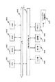
【図6】ネットワーク同期機構を備えた複数カメラ映像の同期収録構成について説明する図である。
【図7】DVキャプチャボードにより構成される映像信号処理部の構成例について説明する図である。
【図8】サーバーPCで実行する同期調整処理の詳細について説明する図である。
【図9】一台のカメラで観測した発光球体の時系列画像(t=1,……,k)について説明する図である。
【図10】特徴点抽出処理として実行される発光球体の中心点位置判定処理の手順を説明する図である。
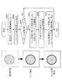
【図11】隣接カメラで観測された時系列画像から、それぞれ球体の中心位置を検出し、一枚の画像から抽出された特徴点のように設定する処理を説明する図である。
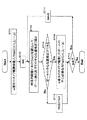
【図12】複数フレームからなる時系列画像に基づいて、それぞれの画像フレームから特徴点としての球体中心位置を求める処理手順を示すフローチャートを示す図である。
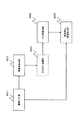
【図13】本発明のキャリブレーション処理装置の機能構成を説明するブロック図である。
【図14】本発明のキャリブレーション処理装置の実行する最適なF行列の算出処理手順について説明する図である。
【図15】エピポーララインについて説明する図である。
【図16】エピポーララインの生成と、F行列推定に使われた対応点とエピポーララインとの距離(誤差)の算出処理について説明する図である。
【図17】特徴点分布判定処理について説明する図である。
【図18】本発明に係るキャリブレーション処理装置の具体的なハードウェア構成例について説明する図である。
【符号の説明】
100 被写体
101,102 カメラ
111,112 実写画像
113 仮想視点カメラ
121 仮想視点カメラ画像
301 カメラ
302 実写画像
301 カメラ
320 同期信号発生部
330 A/Dコンバータ
350 クライアントPC
355 映像信号処理部
356 記憶手段
357 ネットワークカード
360 画像モニタ
370 サーバーPC
380 ネットワーク
391 CPU
392 RAM
393 ROM
394 1394ポート
395 LINK/PHY
396 記憶手段
500 発光球体
501,502 カメラ
511,512 特徴点分布データ
601 画像入力部
602 特徴点抽出部
603 対応付け処理部
604 F行列算出部
605 仮想視点画像生成部
901 CPU
902 ROM
903 RAM
904 HDD
905 入力部
906 出力部
907 通信部
908 ドライブ
909 リムーバブル記録媒体
910 バス
911 入出力インタフェース[0001]
TECHNICAL FIELD OF THE INVENTION
The present invention relates to a calibration processing device, a calibration processing method, and a computer program. More specifically, a parameter applied to adjustment between multi-view image capturing cameras that generates a multi-view image by shooting a subject with a plurality of cameras arranged at different positions, or correction processing of an acquired image of the multi-view image capturing camera The present invention relates to a calibration processing device that performs a calculation process, a calibration processing method, and a computer program.
[0002]
[Prior art]
2. Description of the Related Art In recent years, use of image data, such as panorama and omnidirectional images, in which a viewpoint can be variously moved has become active. For example, when an image of a subject captured from a plurality of viewpoint positions and line-of-sight directions is stored in a storage medium such as a DVD or a CD, and the stored image is displayed on a CRT or a liquid crystal display device, the user operates the controller to operate the controller. A system for observing an image of a subject by moving a viewpoint to a free position has been realized. In addition, images obtained by photographing a subject from a plurality of viewpoint positions and line-of-sight directions are distributed via a communication system such as the Internet, and a user operates a mouse on a PC or the like to display an image from a desired viewpoint position and line-of-sight direction on a display. A display system and the like are constructed.
[0003]
With the improvement of computer processing capability and the development of various video media playback devices, it became possible to process huge polygon data and video data (content), which were previously difficult, and images were taken with multiple cameras with different viewpoints. 2. Description of the Related Art It has become possible to process video data of the real world (target) by a computer, a video device, or the like, and generate and present a video of an arbitrary viewpoint according to a user's request in real time.
[0004]
In order to generate and present an arbitrary viewpoint video from images captured from a plurality of viewpoints by processing on a computer, (1) all cameras must be able to see the same area (target), (2) It is necessary that the positional relationship between the cameras can be obtained.
[0005]
Although it is possible to generate a virtual viewpoint video taken by a virtual camera at an arbitrary position between the real cameras based on a multi-view video taken by a plurality of cameras having different viewpoints focusing on the same object by image processing, In order to generate a high-precision virtual viewpoint video, it is necessary to accurately determine the positional relationship between the real cameras. There is a geometry parameter as a parameter indicating the positional relationship between the actual photographing cameras. The geometry parameters are represented by a determinant, which is called a fundamental matrix or an F matrix.
[0006]
Many methods have been proposed so far for finding a fundamental matrix representing the positional relationship between the real cameras. For example, several (adjacent) cameras simultaneously observe a checker pattern in a three-dimensional space, extract characteristic points (for example, intersection positions of black and white patterns) on a checker pattern image, and associate the characteristic points with each other. , A method of estimating a fundamental matrix is known (for example, Non-Patent Document 1).
[0007]
However, (1) at an actual shooting site, it is not always possible to accurately determine a corresponding point from a captured checker pattern image due to the influence of illumination light (for example, reflected light) or the like. (Expressed as F matrix) is not easy to estimate. (2) Also, when observing the same checker pattern plate with a number of cameras having different viewpoints, the observation camera is often not directly facing the checker pattern plate. There is a problem that it is not easy to accurately detect a feature point position in a checker pattern image.
[0008]
(3) Further, when a large number of cameras are arranged so as to surround the same object (subject), not only is the photographed checker pattern deformed, but if a planar checker pattern is used, the checker pattern can be shifted by 360 degrees. Even if the cameras are arranged so as to surround the periphery, all cameras cannot simultaneously photograph the same checker pattern. In this case, it is necessary to divide the multi-view camera into some groups and to photograph the checker pattern by a plurality of cameras a plurality of times, which consumes much labor and time. (4) Further, when performing camera calibration, it is clear about a process for determining whether checker image patterns for estimating the F matrix have been sufficiently recorded and whether the spatial positions of the checker patterns are appropriate. There is no standard, and there is a problem that the accuracy of the resulting F matrix is not guaranteed.
[0009]
[Non-patent document 1]
R. Y. Tsai: An Efficient and Accurate Camera Calibration Technique for 3D Machine Vision, Proceedings of IEEE Conference on Computer Relations, Vision and Compliance. 364-374 (1986)
[0010]
[Problems to be solved by the invention]
The present invention has been made in view of the above-described problem, and highly accurately calculates a geometry parameter (Geometry Parameter) which is a parameter indicating a positional relationship between real shooting cameras included in a multi-view video imaging system. It is an object of the present invention to provide a camera calibration device, a camera calibration method, and a computer program that enable high-speed and high-precision camera calibration.
[0011]
The present invention uses a light-emitting sphere that is less likely to affect the lighting environment or the like as a calibration jig, estimates the F matrix while detecting and associating the center position of the sphere in real time, and compares the estimated F matrix with the corresponding point. By evaluating errors and positional relationships, the number of necessary corresponding points and the position of a sphere to be placed in a three-dimensional space are designated, and a more accurate F matrix is automatically estimated.
[0012]
Since the shape of the sphere does not depend on the camera observation viewpoint position, it can be observed by all cameras at various viewpoint positions. In addition, it is possible to perform camera calibration while observing and photographing a sphere image using a multi-viewpoint video photographing system having a synchronization function and recording the spherical image on a recording medium such as a memory or a hard disk of each personal computer. Then, the coordinate position (feature point) of the center of the sphere in each frame image is extracted by an image processing method on each personal computer, and a fundamental matrix is estimated by associating the extracted feature points with the images. Furthermore, the accuracy of the estimated F matrix is evaluated, and the number of corresponding points and the appropriate positions of the corresponding points, that is, the spatial positions of the spheres are automatically presented. Provided are an apparatus and a method for implementing objective estimation.
[0013]
[Means for Solving the Problems]
According to a first aspect of the present invention,
It is a calibration processing device that performs a parameter calculation process applied to the adjustment between the multi-view image shooting cameras or the correction process of the acquired image by the multi-view image shooting camera,
An image input unit for inputting video data of a plurality of cameras capturing a moving sphere from different viewpoint directions,
A feature point extraction unit that executes a process of extracting a sphere center position as a feature point from a plurality of captured image frames constituting video data of a plurality of cameras input in the image input unit,
An association processing unit that executes an association process of a sphere center position extracted by the feature point extraction unit as a feature point in a corresponding frame of each camera;
An F matrix calculation unit that calculates a fundamental matrix as a calibration parameter based on the feature point correspondence data associated in the association processing unit;
And a calibration processing device.
[0014]
Further, in one embodiment of the calibration processing device of the present invention, the sphere is a light-emitting sphere, and the feature point extracting unit calculates a sphere center position based on edge information of the sphere captured in a frame. Is performed.
[0015]
Further, in one embodiment of the calibration processing device of the present invention, the F matrix calculation unit sets an epipolar line based on the calculated F matrix, and calculates a relationship between the set epipolar line and a sphere center position corresponding to a feature point. The distance is calculated individually or as an average distance, and when the calculated distance is larger than a predetermined threshold, the F matrix is recalculated based on feature point correspondence data including a new feature point. It is characterized by the following.
[0016]
Furthermore, in one embodiment of the calibration processing device of the present invention, the F matrix calculation unit executes a sphere center position in a captured image frame, that is, a distribution state determination process of feature points, and a feature point uneven distribution is confirmed. In this case, the configuration is such that the F matrix recalculation processing is performed based on feature point correspondence data including a feature point additionally set at a position where the uneven distribution is eliminated.
[0017]
Further, in one embodiment of the calibration processing device of the present invention, the feature point extracting unit executes the center position calculating process based on the edge information only when an edge of the entire sphere exists in the shooting frame. It is characterized by being.
[0018]
Further, in one embodiment of the calibration processing device of the present invention, the feature point extracting unit calculates at least eight spherical center position data required for calculating a ratio of nine elements of the F matrix. Acquired from a plurality of captured image frames of a camera, the associating processing unit executes associating processing of eight or more sphere center positions extracted by the feature point extracting unit, and the F matrix calculating unit It is characterized in that it is configured to execute element value calculation of a fundamental matrix as a calibration parameter based on the attached eight or more feature point corresponding data.
[0019]
Further, a second aspect of the present invention provides
It is a calibration processing method for performing adjustment between multi-viewpoint image capturing cameras, or parameter calculation processing applied to correction processing of an acquired image of the multi-viewpoint image capturing camera,
An image input step of inputting video data of a plurality of cameras that photograph a moving sphere from different viewpoint directions,
A feature point extraction step of extracting a sphere center position as a feature point from a plurality of captured image frames constituting video data of a plurality of cameras input in the image input step;
An associating processing step of executing a feature point associating process based on the sphere center position extracted in the feature point extracting step;
An F matrix calculation step of calculating a fundamental matrix as a calibration parameter based on the feature point correspondence data associated in the association processing step;
A calibration processing method characterized by having the following.
[0020]
Further, in one embodiment of the calibration processing method of the present invention, the sphere is a light-emitting sphere, and the feature point extracting step includes calculating a sphere center position based on edge information of the sphere captured in a frame. It is characterized by executing.
[0021]
Further, in one embodiment of the calibration processing method of the present invention, the F matrix calculating step sets an epipolar line based on the calculated F matrix, and sets a distance between the set epipolar line and a spherical center position as the feature point. Is calculated individually or as an average distance, and when the calculated distance is larger than a predetermined threshold, an F matrix recalculation process is performed based on feature point correspondence data including a new feature point.
[0022]
Further, in one embodiment of the calibration processing method of the present invention, the F matrix calculation step executes a center position of a sphere in a captured image frame, that is, a distribution state determination process of feature points, and a feature point uneven distribution is confirmed. In this case, an F matrix recalculation process is performed based on feature point correspondence data including an additional feature point additionally set at a position where the uneven distribution is eliminated.
[0023]
Further, in one embodiment of the calibration processing method according to the present invention, the feature point extracting step performs a center position calculation process based on the edge information only when an edge of the entire sphere exists in the shooting frame. It is characterized by.
[0024]
Further, in one embodiment of the calibration processing method of the present invention, the feature point extracting step includes a step of extracting at least eight spherical center position data required for calculating a ratio of nine elements of the F matrix. Acquiring from a plurality of captured image frames of the camera, the associating processing step executes associating processing of eight or more spherical center positions extracted in the feature point extracting step, and the F matrix calculating step includes: The method is characterized in that element values constituting a fundamental matrix as a calibration parameter are calculated based on the attached data of eight or more feature points.
[0025]
Further, a third aspect of the present invention provides
A computer program for performing adjustment between multi-viewpoint image capturing cameras, or parameter calculation processing applied to correction processing of an acquired image of a multi-viewpoint image capture camera,
An image input step of inputting video data of a plurality of cameras that photograph a moving sphere from different viewpoint directions,
A feature point extraction step of extracting a sphere center position as a feature point from a plurality of captured image frames constituting video data of a plurality of cameras input in the image input step;
An associating process step of executing an associating process of the sphere center position extracted in the feature point extracting step,
An F matrix calculation step of calculating a fundamental matrix as a calibration parameter based on the feature point correspondence data associated in the association processing step;
A computer program characterized by comprising:
[0026]
[Action]
According to the configuration of the present invention, in a calibration process for performing adjustment between multi-viewpoint image capturing cameras or a parameter calculation process applied to a correction process of an acquired image by the multi-viewpoint image capturing camera, a luminous sphere is captured by each camera. Sphere detection and acquisition of the sphere center position can be easily performed even in a shooting site where the lighting environment is unstable, and highly accurate by executing the matching process using the sphere center position as a feature point. Calculation of the F matrix becomes possible. In other words, it is possible to calculate a fundamental matrix as a geometry parameter, which is a parameter indicating a positional relationship between real shooting cameras included in the multi-view video imaging system, with high accuracy, and to achieve high speed and high speed. Accurate calibration becomes possible.
[0027]
Furthermore, according to the configuration of the present invention, an F matrix is estimated while detecting and associating the center position of the sphere in real time using the light emitting sphere as a calibration jig, and the error between the estimated F matrix and the corresponding point is determined. By evaluating the position and the positional relationship, it is possible to indicate the number of necessary corresponding points and the position of a sphere to be placed in a three-dimensional space, and efficiently calculate a more accurate F matrix.
[0028]
Furthermore, according to the configuration of the present invention, it is possible to perform camera calibration while observing and photographing a sphere image using a multi-view video photographing system having a synchronization function and recording the spherical image on a recording medium such as a memory or a hard disk on each personal computer. It is possible to extract the coordinate position (feature point) of the center of the sphere in each frame image by using an image processing method on each personal computer, and to estimate and estimate a fundamental (Fundamental) matrix by associating the images using the extracted feature points. Matrix accuracy evaluation, determination of the number of corresponding points and appropriate positions of corresponding points, presentation, etc. can be executed on, for example, a PC, and high-speed and high-precision calibration processing is executed on a simple system such as a PC. It is possible to do.
[0029]
The computer program of the present invention is provided, for example, in a computer-readable format for a general-purpose computer system capable of executing various program codes, in a storage medium or communication medium such as a CD, FD, or MO. And a computer program that can be provided by a communication medium such as a network. By providing such a program in a computer-readable format, processing according to the program is realized on a computer system.
[0030]
Further objects, features, and advantages of the present invention will become apparent from a more detailed description based on embodiments of the present invention described below and the accompanying drawings. In this specification, the term “system” refers to a logical set of a plurality of devices, and is not limited to a device having each component in the same housing.
[0031]
BEST MODE FOR CARRYING OUT THE INVENTION
Hereinafter, a camera calibration device, a camera calibration method, and a computer program of the present invention will be described in detail with reference to the drawings.
[0032]
First, with reference to FIG. 1, a description will be given of a multi-view camera photographing process and a process of generating a virtual viewpoint video using a real shot video captured by the multi-view camera. The subject 100 is photographed by a plurality of cameras arranged around the subject 100. Each camera captures an image of the subject 100 from a different viewpoint. Real images are acquired in accordance with the number of cameras to be arranged. However, a real image between cameras cannot be obtained. Therefore, the image between the cameras, that is, the image of the virtual viewpoint, is generated by image processing based on the real image.
[0033]
For example, when no camera is arranged between the camera A101 and the camera B102, an image between the camera A101 and the camera B102 is generated based on two
[0034]
View interpolation is a technique for generating an image viewed from a viewpoint without an actual camera from images from a plurality of cameras. For this view interpolation, for example, [S. M. Seitz and C.I. R. Dyer, "View Morphing," Proc. SIGGRAPH 96, ACM, 1996 pp. 21-30. ]It is described in. According to the view interpolation, it is possible to generate an image of a viewpoint without a camera based on an actually acquired image based on a plurality of cameras.
[0035]
For example, in order to generate a virtual
[0036]
As shown in FIG. 2, the correction process using the calibration parameters required for generating the virtual viewpoint image includes a distortion parameter including a distortion coefficient (Distortion Coefficient), a distortion center (Distortion Center), and an aspect ratio (Aspect Ratio). Parameter correction based on, and internal parameters [A] consisting of scale factors, torsion, image center data, and camera internal / external parameters based on external parameters [T, R] consisting of translation [T] and rotation [R] vectors There is a correction. Regarding camera distortion parameters, generally, checker patterns, straight lines, and the like are photographed by a plurality of cameras that execute calibration, and adjustment parameters between cameras are estimated based on photographed images of the checker patterns, straight lines, and the like.
[0037]
The camera internal / external parameters [A, T, R] are expressed by a determinant indicating geometry parameters (Geometry Parameters) as parameters indicating the positional relationship between the real cameras. This is called a fundamental matrix (F matrix). The F matrix is represented by the following equation (Equation 1).
[0038]
(Equation 1)
Several methods have already been proposed for obtaining a fundamental matrix between cameras represented by the above equation. A general method for obtaining a fundamental matrix will be briefly described.
[0040]
FIG. 3 shows a general method of estimating F matrix parameters. First, as shown in FIG. 3A, an image pattern (for example, a checker pattern) as a calibration jig in a three-dimensional space is photographed several times by the
[0041]
After the feature points are extracted, as shown in FIG. 3B or the following equation, an F matrix is obtained by associating the extracted feature points m1i with m2i (i = 1, 2,... N). Can be estimated.
[0042]
(Equation 2)
In the above equation, f is W T By calculating as an eigenvector corresponding to the minimum eigenvalue of W, the elements of the F matrix can be obtained.
[0044]
FIG. 4 is a diagram showing a camera calibration procedure when a checker pattern is used as a calibration jig in order to actually estimate the F matrix.
[0045]
First, in step S101, a checker pattern as a calibration jig is photographed by the
[0046]
Next, in step S102, feature points m1 (x, y) and m2 (x, y) in the checker pattern images I1 (x, y) and I2 (x, y) taken by the
[0047]
The association process is a matching process that associates pixels in a plurality of images obtained by photographing the same object. 2. Description of the Related Art Conventionally, methods of “association” that are often used include, for example, Pixel-based matching, Area-based matching, and Feature-based matching. Pixel-based matching is a method of searching for the correspondence of points in one image as it is in the other image. Area-based matching is a method of searching for the correspondence of a point in one image by using a local image pattern around the point when searching in the other image. Feature-based matching is a method of extracting features such as dark and light edges from images and performing correspondence using only features between images. Pixels are associated with each other based on feature points extracted from a plurality of images using these methods.
[0048]
Finally, in step S104, an F matrix is calculated by applying the above-described equation (Equation 2) based on the acquired corresponding points. That is, by associating the extracted feature points m1i and m2i (i = 1, 2,... N), f is represented by W T By calculating as an eigenvector corresponding to the minimum eigenvalue of W, an F matrix, that is, a fundamental matrix (= F parameter) is obtained.
[0049]
However, in the above-described method, when the camera and the checker pattern plate do not face each other, there is a problem that the extraction accuracy of feature points is reduced. In addition, due to the arrangement of a plurality of cameras, there is a problem that a checker pattern cannot be observed at the same time by each camera, and that the correspondence of feature points between images is affected by the quality of a captured image, and processing time is increased. .
[0050]
As a method for solving these problems, in the present invention, a moving luminous sphere is used as a calibration tool instead of a planar checker pattern, and a plurality of cameras that photograph the luminous sphere from different directions are installed, and each camera image is set. Is performed, a fundamental matrix (= F parameter) is calculated based on the recorded image, and camera calibration is performed. ADVANTAGE OF THE INVENTION According to the structure of this invention, it is efficient and highly accurate without the problem that the characteristic point extraction precision falls by imaging a checker pattern of a plane from a different direction, and the checker pattern cannot be observed by each camera simultaneously. You can execute simple camera calibration.
[0051]
FIG. 5 shows a configuration example in which a moving luminous sphere is used as a calibration tool, and an issuance sphere is photographed from a different viewpoint. FIG. 6 shows an example of the configuration of a synchronous recording processing device for recorded video of each camera.
[0052]
As shown in FIG. 5, cameras 301-1 to N for performing camera calibration are arranged around a
[0053]
The advantages of using a luminous sphere as shown in FIG. 5 are that (1) the sphere can be easily detected from an image observed in an arbitrary background and environment, and (2) the sphere has the same shape with a camera at an arbitrary viewpoint position. (3) The center position of the sphere in the image can be accurately estimated, and (4) The corresponding point processing between the images using the center of the sphere extracted from the time-series image can be easily performed. It is in.
[0054]
In order to estimate the F matrix, the nine elements (f 11 , F 12 , ... f 33 ) Must be determined. This is substantially equivalent to obtaining the ratio of the nine elements of the F matrix and obtaining the solution of the equation having eight unknowns. Therefore, it is necessary to set relational expressions for a large number of corresponding points (at least eight points or more).
[0055]
In the configuration of the present invention, a moving luminous sphere is photographed, and the center position of the luminous sphere is extracted as a feature point for each frame along the time axis, and a plurality of feature points extracted from the frame along the time axis are extracted. Are used as if they were extracted from one shot image, and are used for association between images. For example, if shooting is performed at 30 frames / second for 5 seconds, 30 × 5 = 150 frames can be shot by each camera, and 150 feature points (= sphere center position) can be extracted.
[0056]
In order to automatically perform such feature point extraction and association, a synchronous recording apparatus for a plurality of camera images provided with a network synchronization mechanism as shown in FIG. 6 is applied.
[0057]
The
[0058]
Each camera output video is a video signal such as a Y / C signal or the like as a difference signal (C) between a luminance signal (Y) and an RGB color component signal, and each camera sets a video signal corresponding to each camera. Input to the converted
[0059]
The client PC (PC1 to PCn) 350 as an image recording processing device includes a
[0060]
The video signal input from the
[0061]
The plurality of
[0062]
FIG. 7 shows a configuration example of the video
[0063]
An
[0064]
The
[0065]
The
[0066]
The program stored in the
[0067]
As described above, the reference video signal (synchronization signal) from the
[0068]
With reference to FIG. 8, the details of the synchronization adjustment process executed by the server PC will be described. First, in step S301, the server PC reads the recording frame number data of each PC at each measurement point input from each client PC. This is the data shown in the data example (a) of FIG. 8, for example.
[0069]
Here, it is assumed that the server PC has acquired the recording frame numbers at four measurement points (measurement points 1 to 4) from a plurality of client PCs (PC1 to PCn).
[0070]
According to the list of recording frame numbers of each PC at each measurement point input from each client PC in FIG. 8A, for example, PC1
At measuring
At measuring
At measuring
At measuring
Indicates that the frame number is stored at each measurement point in response to the “save current recording frame number” command from the server PC.
[0071]
Next, in step S302, the server PC receives the frame No. in the PC having a large processing delay amount, in this case, the
[0072]
As a result of this processing, the frame shift amount of the video recorded in each PC at each measurement point (b) shown in FIG. 8 is obtained. In the example shown in FIG. 8, PC2 is used as a reference, and PC2 has a displacement amount = 0 at all measurement points. Further, for example, the displacement amount of PC1 is obtained at each measurement point by the recording processing frame of PC1−the recording processing frame of PC2. As a result, the displacement amount of PC1 is
At
At
At the
At
It becomes.
[0073]
For other PCs, PC3 to PCn, the recording frame No. with PC2 is also included. Is obtained as a shift amount.
[0074]
Next, in step S303, a process of determining the shift amount of each PC from the reference PC = PC2 is performed. This is performed, for example, by calculating the average value of the shift amounts at each measurement point of each PC, and calculating an integer value based on the average value by rounding.
[0075]
FIG. 8C shows data obtained by calculating the average value of the shift amount at each measurement point of each PC. The deviation amount of PC1 from PC2 is
(3 + 3 + 3 + 4) /4=3.25
It becomes.
[0076]
FIG. 8D shows data obtained by rounding off the average value of the shift amount at each measurement point of each PC.
The shift amount of PC1 with respect to PC2 is 3,
The shift amount of PCn with respect to PC2 is 2.
In this way, the amount of deviation of each client PC from the reference PC (PC2) is determined.
[0077]
Next, in step S304, the server PC executes a synchronization adjustment process of each client PC based on the calculated shift amount of each PC.
[0078]
The processing frame No. at each
At
At
At
At
Is set.
[0079]
For example, the PC1 setting frame No. Is the setting frame No. of the reference PC (PC2). Is determined to be 3, and a value obtained by subtracting the
[0080]
Executing the synchronization adjustment processing in each client PC in this manner enables accurate inter-frame synchronization.
[0081]
By the above-described processing, each camera image can be acquired completely synchronously. The calibration device of the present invention executes the process of associating the center of the luminous sphere as a feature point with respect to each of the image capturing frames on which the above-described synchronization adjustment has been performed, and according to the procedure described with reference to FIG. Find the F matrix.
[0082]
FIG. 9 shows a time-series image (t = 1,..., K) of the light emitting sphere observed by one camera (
[0083]
In the configuration of the present invention, the center point of the luminous sphere is a feature point for executing the association processing. The process of obtaining the center point of the light emitting sphere is executed in each frame of each camera photographed image. In order to determine the elements of the F matrix, it is necessary to associate at least eight feature points as described above, and feature points are extracted from an image captured by a camera performing calibration in at least eight frames. The process of determining the center position of the light-emitting sphere performed as the feature point extraction process will be described with reference to FIG.
[0084]
The procedure of the center point position determination process of the light emitting sphere executed as the feature point extraction process in the configuration of the present invention will be described with reference to the process flow of FIG. FIG. 10 shows a processing flow for obtaining the center pixel position of a sphere from one frame image. First, in step S501, a captured image frame of a light emitting sphere is input.
[0085]
In step S502, a sphere edge is detected from the input image. If the coordinate values of the edge pixels are in contact with the four sides of the acquired frame image, it is determined that a part of the sphere is missing, and no feature point is extracted in that frame (time). This determination processing is step S503.
[0086]
When the entire light-emitting sphere is observed as an image in the input frame (step S503: Yes), in step S504, the initial center position of the sphere is determined by projection processing based on the coordinate values of the edge pixels. Specifically, the difference between the xy coordinate values of the pixels on the left and right edges of the sphere is projected on the X axis and the Y axis, the distribution for X and Y is obtained, and the maximum position of each is determined by the initial center (xs, ys) of the sphere. ) And size (radius).
[0087]
In step S505, the estimated initial center and size are applied to the circular model, and a pixel point on an edge largely deviating from the model is deleted as an exceptional point (Outlier). Finally, in step S506, the edge pixel point after removing the exceptional point (Outlier) is applied to the circular model to determine the center position (and size) of the sphere.
[0088]
FIG. 11 is a diagram illustrating a processing example in which the center position of each sphere is detected from the time-series images observed by the adjacent cameras and set as if they were feature points extracted from one image.
[0089]
It is assumed that an F matrix for camera calibration for adjustment processing between the
[0090]
In the configuration of the present invention, the characteristic point is the center position of the luminous sphere in the luminous sphere photographed image, and the center position of the luminous sphere in each frame is extracted as the characteristic point. Each frame image of the shooting frames t = 1 to k of the
[0091]
As described above, by determining at least eight feature points and executing the association process, the elements of the F matrix including nine elements can be determined. From the synchronous frame image, at least eight frames from which the center position of the luminous sphere can be obtained are selected, and their characteristic points (sphere center position) are obtained. When they are combined into one, feature
[0092]
The feature
[0093]
The feature
[0094]
Corresponding feature points of these feature
[0095]
FIG. 12 is a flowchart illustrating a processing procedure for obtaining a sphere center position as a feature point from each image frame based on a time-series image including a plurality of frames. Each processing step of the flowchart shown in FIG. 12 will be described. Here, the camera number of the feature point extraction processing target. Is m, and the camera No. Let m be the number of image frames taken.
[0096]
In step S701, the observation (photographed) image Im (t) (t = 1, 2,..., K) of the m-th (m = 1, 2,..., N) camera is input to the calibration processing device. .
[0097]
In step S702, t = 1 is sequentially set as an initial value of a processing frame for executing processing for each frame. In step S703, the camera image Im (t) is read, and processing for detecting a sphere in the read frame and estimating the center position thereof is performed according to the procedure described above with reference to FIG.
[0098]
If the image of the sphere is not detected in the image to be processed or if the entire sphere is not included (Step S704: No), the sphere center position estimation process is not executed as described above, but the calibration processing device In step S712, Pm (t) = Null is stored in the memory as the result, that is, frame-corresponding data indicating that the center position has not been determined.
[0099]
When the whole sphere is detected in the image, the center position of the sphere is estimated in accordance with the method of FIG. 10 described above, and the result is stored in step S705 as the center position data Pm (t) corresponding to the frame. To save.
[0100]
Here, Pm (t) means the sphere center position of the t (t = 1,..., N) frame in the m-th camera image. In step S706, it is determined whether or not processing of all frames has been completed, that is, [t <k? Is performed, and if there is an unprocessed frame, an update process of [t = t + 1] is executed in step S711, and a sphere center position estimation process and a save process are executed in step S703 and subsequent steps. .
[0101]
The process shown in FIG. 12 is executed for all N cameras, and the center position Pm (t) of the ball (light emitting sphere) in a plurality of frames is obtained from all the camera images.
[0102]
A set of feature point distribution data shown in FIG. 11 was configured and configured by using a set of frames excluding a frame whose center position was not determined from photographed frames of an adjacent camera or a distant camera performing the calibration process. An F matrix is calculated by executing a feature point association process of a corresponding frame in the feature point distribution data. The process of calculating the F matrix by associating the feature points is executed by the same method as described above with reference to FIGS. When the F matrix is determined, it is possible to perform correction processing of the captured image of each camera using the F matrix, and it is possible to generate a highly accurate virtual viewpoint camera image from actual captured images of a plurality of cameras.
[0103]
FIG. 13 is a block diagram illustrating the functional configuration of the calibration processing device according to the present invention. Various processes executed in the calibration processing device of the present invention can be executed as processes according to a computer program. Specifically, various processes are executed under the control of the CPU as a control unit. FIG. 13 is a block diagram for explaining processing executed by the CPU as the control means individually and explaining a function executed by the calibration processing apparatus of the present invention. A specific hardware configuration will be described later.
[0104]
The block diagram of FIG. 13 will be described. The
[0105]
The feature
[0106]
When the associating process is executed, the F
[0107]
The obtained F matrix is output to the virtual viewpoint
[0108]
Note that calibration as adjustment processing of the camera itself may be executed based on the calculated F matrix. Whether to correct the acquired image or to adjust the camera itself is optional.
[0109]
As described above, from a multi-view video taken by multiple cameras with different viewpoints focusing on the same object, an arbitrary virtual viewpoint video is created between those live-action cameras as if it were shot by a virtual camera In order to express the position, it is necessary to accurately determine the positional relationship between the actual cameras. An accurate positional relationship between the two cameras is obtained by a fundamental matrix as a parameter indicating the positional relationship between the real cameras, and correction and synthesis of captured images based on the obtained positional relationship can be performed with high accuracy. In addition, it is possible to generate a highly accurate image of a virtual viewpoint camera that is not actually photographed between two cameras.
[0110]
Next, with reference to the flowchart shown in FIG. 14, a description will be given of an optimal F matrix calculation processing procedure executed by the calibration processing apparatus of the present invention.
[0111]
In step S801, first, the luminous sphere is placed at a position where each camera to be calibrated can observe. For example, a light-emitting sphere is placed and moved where the optical axis of each camera intersects. In step S802, the moving luminous sphere is photographed by each camera. In the photographing process, as described with reference to FIGS. 5 to 8, the photographed frames of each camera are acquired as synchronized frames.
[0112]
In step S803, the center position of a sphere as a feature point is detected from the image captured by each camera. The detection of the sphere center position is performed according to the procedure described with reference to FIGS.
[0113]
In step S804, a process of associating the camera images to be calibrated is performed with the detected sphere center position as a feature point of each camera image. The feature point associating process is executed according to the procedure described with reference to FIGS.
[0114]
In step S805, it is determined whether the number of corresponding points has reached eight. As described above, in order to calculate the ratio of the nine elements of the F matrix, it is necessary to associate eight feature points. If the number of corresponding points is less than 8, the process returns to step S801, and the images captured by a plurality of cameras to be subjected to the calibration process are acquired while moving the light emitting sphere to change the position of the sphere.
[0115]
If the number of corresponding points has reached eight or more, the process proceeds to step S806, where an F matrix is calculated based on the corresponding points of the feature points. The calculation of the F matrix is performed according to the equation (Equation 2) as described with reference to FIGS. Note that an image captured by a camera is captured at a rate of, for example, 30 frames / second for several seconds in a single capturing process, so that 100 or more frames are acquired, and feature point extraction processing is performed from these many frames. You.
[0116]
Therefore, feature points to be matched are randomly selected from 100 or more feature points, and feature point matching processing is performed based on the selected points. Further, the calculation of the F matrix is executed based on the associated feature points. However, since the association of the feature points is performed based on the correlation between the images, the association processing is often performed by mistake. If there is such an error, an accurate F matrix cannot be obtained. Therefore, it is necessary to perform a process of obtaining an accurate F matrix by excluding a combination of feature points that are erroneously associated.
[0117]
The processing in step S807 and subsequent steps is processing for eliminating feature points determined to be inappropriate for the calculation of the F matrix, such as feature points that have been incorrectly associated.
[0118]
In step S807, an epipolar line is calculated using the calculated F matrix. Further, in step S808, the distance (error) between the corresponding point used in the F matrix estimation and the epipolar line is calculated. If the error is larger than a predetermined threshold, the position of the sphere is changed, its center is detected, and a new corresponding point is obtained.
[0119]
With reference to FIGS. 15 and 16, the processing of steps S807 and S808, that is, the generation of the epipolar line and the calculation processing of the distance (error) between the corresponding point used in the F matrix estimation and the epipolar line will be described. First, generation of an epipolar line will be described. An epipolar line is a line set based on the positional relationship between two cameras, and is generally generated by parallax detection using a stereo method.
[0120]
The principle of the stereo method will be briefly described. The stereo method associates pixels in multiple images obtained by photographing the same object from two or more viewpoints (different line-of-sight directions) using a plurality of cameras to associate the position of the measurement object in a three-dimensional space. It is what we seek. For example, the same object is photographed from different viewpoints by the reference camera and the detection camera, and the distance between the measurement objects in each image is measured based on the principle of triangulation.
[0121]
FIG. 15 is a diagram illustrating the principle of the stereo method. The reference camera (Camera 1) and the detection camera (Camera 2) photograph the same object from different viewpoints. Consider finding the depth of a point “mb” in an image captured by a reference camera.
[0122]
Objects that appear at the point “mb” in the image captured by the reference camera are “m1”, “m2”, and “m3” in images captured by the detection cameras capturing the same object from different viewpoints. It will be developed on a straight line. This straight line is referred to as an epipolar line Lp.
[0123]
The position of the point “mb” in the reference camera appears on a straight line called “epipolar line” in the image obtained by the detection camera. As long as the point P to be imaged (a point existing on a straight line including P1, P2, and P3) is on the line of sight of the reference camera, regardless of the depth, that is, the distance from the reference camera, on the reference image. Appears at the same observation point "mb". On the other hand, the point P on the image captured by the detection camera appears on the epipolar line at a position corresponding to the magnitude of the distance between the reference camera and the observation point P.
[0124]
In the configuration of the present invention, feature points are extracted based on the images captured by the two cameras to be calibrated, and the F matrix is calculated in step S806 based on the extracted feature points. The F matrix is a parameter indicating a positional relationship between the two cameras, and an epipolar line can be set based on the positional relationship parameter.
[0125]
The setting of the epipolar line will be described with reference to FIG. FIGS. 16A and 16B are diagrams collectively showing feature points (sphere centers) obtained in a plurality of frames captured by a camera to be subjected to calibration processing. This corresponds to the feature
[0126]
For example, from the F matrix estimated using the corresponding points mli (i = 1,..., P) and m2i (i = 1,..., P) in the images of the
[0127]
[Equation 3]
Based on the above equation (Equation 3), one straight line (epipolar line) shown in the following equation (Equation 4) is set.
[0129]
(Equation 4)
However, the feature points used for the F matrix calculation are feature points randomly selected from a large number of feature points existing in a large number of frames captured by the two cameras. If the F matrix is calculated correctly, the feature points will be on the epipolar line set based on the F matrix, but the feature points have not been accurately extracted or matched. Then, the feature point becomes a position shifted from the epipolar line. If the deviation is large, the feature point association processing is inaccurate, and it is determined that the F matrix is also inaccurate.
[0131]
As an index for determining the accuracy of the F matrix, a distance Di between the feature point and the epipolar line is calculated. As shown in FIG. 16, the epipolar lines L1, L2,... Li set based on the F matrix and each feature point m21, m22,. . m2i and distances D1, D2,. . Find Di.
[0132]
In step S809, each of the calculated distances D1, D2,. . Di is compared with a predetermined threshold value. If there is a feature point m2i having a distance larger than the threshold value, in step S810, the set of feature points, that is, the set of feature points m1i and m2i of
[0133]
In step S809, each of the calculated distances D1, D2,. . If all Di are equal to or less than a predetermined threshold, in step S811, each of the calculated distances D1, D2,. . An average value of Di is calculated, and the average value is compared with a predetermined second threshold value. If the average distance value is equal to or greater than the second threshold value, the F matrix is calculated again in step S806 based on the association processing data of other associateable feature points.
[0134]
In step S811, each of the calculated distances D1, D2,. . If the average value of Di is less than the second threshold, the process proceeds to step S812, and the distribution of feature points is determined. The feature point distribution determination processing will be described with reference to FIG. When the feature points for executing the association processing are biased to a part of the captured image frame, it is difficult to obtain an accurate positional relationship between the cameras. That is, it is difficult to calculate an accurate F matrix. Therefore, in order to perform more accurate F-matrix calculation assuming that the feature point distribution for which the association process is performed is scattered over the entire captured image frame, the feature point distribution is checked. A new feature point is set at the position, and the F matrix is calculated again.
[0135]
As shown in FIG. 17, the coordinate values of the corresponding point m1i (i = 1,..., P) on the image of the
[0136]
(Equation 5)
If the coordinate distribution of each camera obtained by each of the above equations is apart from the image center (xc1, yc1) and (xc2, yc2), it is determined that there is uneven distribution of feature points, and a new feature point is added. I do. More specifically, the distance between the coordinate distribution value of each camera obtained by each of the above equations and the image centers (xc1, yc1) and (xc2, yc2) is compared with a third threshold value determined in advance, and If it is large, it is determined that there is a bias in the feature point distribution, and the process advances from step S813 to step S814 to set a necessary feature point position. The additional feature point to be specified is set at a position that reduces the bias of the coordinate distribution obtained in the above equation (Equation 5). For example, points m1k and m2k shown in FIG.
[0138]
In step S815, the sphere is moved to a position where the instructed feature point can be obtained, and thereafter, the process returns to step S802, where camera shooting of the sphere is performed again, an additional feature point is added, and a feature point association process is performed. Execute the F matrix calculation process.
[0139]
If it is determined in step S813 that the feature points are not biased, the process ends with the obtained F matrix as the final F matrix.
[0140]
Thus, the processing procedure of image observation-> sphere detection-> sphere center estimation->association-> F matrix estimation-> epipolar line calculation-> error calculation between corresponding points and epipolar line-> error value evaluation is as follows: Repeat until the error evaluation is smaller than a certain threshold. Further, when the above-mentioned error value becomes smaller than a certain threshold value, it is determined whether or not the position of the corresponding point (that is, the spatial position of the sphere) is biased using the disparity information between the images. If the corresponding points are unbalanced, the spatial position where the sphere should be placed is presented, and the above-mentioned repetitive work is performed. As a result, it is possible to perform high-precision camera calibration even for on-site shooting where the lighting environment is unstable.
[0141]
As described above, according to the processing procedure described with reference to FIG. 14, in the process of associating the sphere center position obtained from the image of the sphere acquired by the camera to be calibrated as a feature point and calculating the F matrix, Even when a feature point selection error for which the association setting is performed or an error occurs in the association process, the error can be corrected. In addition, even when feature points are unevenly distributed, it is possible to check the uneven distribution status, add a feature point to a position not unevenly distributed, and calculate a new F matrix, so that a more accurate F matrix can be calculated. Becomes possible. Therefore, camera calibration based on a high-precision F matrix, or correction processing of an acquired image, and generation of a high-precision virtual viewpoint image based on the correction processing can be performed.
[0142]
Next, a specific hardware configuration example of the calibration processing device according to the present invention will be described with reference to FIG. A CPU (Central processing Unit) 901 is a processor that executes the processing program described with reference to the above-described flowcharts and the OS (Operating System). A ROM (Read-Only-Memory) 902 stores a program executed by the
[0143]
The
[0144]
The
[0145]
The
[0146]
The
[0147]
The present invention has been described in detail with reference to the specific embodiments. However, it is obvious that those skilled in the art can modify or substitute the embodiment without departing from the spirit of the present invention. That is, the present invention has been disclosed by way of example, and should not be construed as limiting. In order to determine the gist of the present invention, the claims described at the beginning should be considered.
[0148]
Note that the series of processes described in the specification can be executed by hardware, software, or a combined configuration of both. When executing the processing by software, the program recording the processing sequence is installed in a memory in a computer embedded in dedicated hardware and executed, or the program is stored in a general-purpose computer capable of executing various processing. It can be installed and run.
[0149]
For example, the program may be recorded in a hard disk or a ROM (Read Only Memory) as a storage medium in advance. Alternatively, the program is temporarily or permanently stored on a removable recording medium such as a flexible disk, a CD-ROM (Compact Disc Only Memory), an MO (Magneto optical) disk, a DVD (Digital Versatile Disc), a magnetic disk, or a semiconductor memory. It can be stored (recorded). Such a removable recording medium can be provided as so-called package software.
[0150]
In addition to installing the program on the computer from the above-described removable recording medium, the program is wirelessly transferred from the download site to the computer, or transferred to the computer via a network such as a LAN (Local Area Network) or the Internet by wire. The computer can receive the program transferred in this way and install it on a storage medium such as a built-in hard disk.
[0151]
The various processes described in the specification may be executed not only in chronological order according to the description but also in parallel or individually according to the processing capability of the device that executes the processes or as necessary.
[0152]
【The invention's effect】
As described above, according to the configuration of the present invention, in the calibration process for performing the adjustment between the multi-viewpoint image capturing cameras or the parameter calculation process applied to the correction process of the acquired image by the multi-viewpoint image capturing camera, Since the luminous sphere is photographed by each camera, it is possible to easily detect the sphere and obtain the center position of the sphere even in a shooting site where the lighting environment is unstable. By executing the calculation, it is possible to calculate the F matrix with high accuracy. In other words, it is possible to calculate a fundamental matrix as a geometry parameter, which is a parameter indicating a positional relationship between real shooting cameras included in the multi-view video imaging system, with high accuracy, and to achieve high speed and high speed. Accurate calibration becomes possible.
[0153]
Further, according to the configuration of the present invention, the luminous sphere which is hardly affected by the lighting environment and the like is used as a calibration jig, and the center of the sphere is detected and associated in real time, and the F matrix is estimated. By evaluating the error and positional relationship between the matrix and the corresponding points, the number of necessary corresponding points and the sphere position to be placed in the three-dimensional space are indicated, and a more accurate F matrix is efficiently calculated. It becomes possible.
[0154]
Furthermore, according to the configuration of the present invention, it is possible to perform camera calibration while observing and photographing a sphere image using a multi-view video photographing system having a synchronization function and recording the spherical image on a recording medium such as a memory or a hard disk on each personal computer. It is possible to extract the coordinate position (feature point) of the center of the sphere in each frame image by using an image processing method on each personal computer, and to estimate and estimate a fundamental (Fundamental) matrix by associating the images using the extracted feature points. Matrix accuracy evaluation, determination of the number of corresponding points and appropriate positions of corresponding points, presentation, etc. can be executed on, for example, a PC, and high-speed and high-precision calibration processing is executed on a simple system such as a PC. It is possible to do.
[Brief description of the drawings]
FIG. 1 is a diagram illustrating a multi-viewpoint camera photographing process and a process of generating a virtual viewpoint video using a real video taken by a multi-viewpoint camera.
FIG. 2 is a diagram illustrating various parameters applied to a calibration process.
FIG. 3 is a diagram illustrating a general F parameter estimation method.
FIG. 4 is a diagram showing a camera calibration procedure when a checker pattern is used as a calibration jig to estimate an F matrix.
FIG. 5 is a diagram showing an example of a configuration in which a luminescent sphere is photographed from different viewpoints using the luminescent sphere as a calibration tool.
FIG. 6 is a diagram illustrating a synchronous recording configuration of a plurality of camera images provided with a network synchronization mechanism.
FIG. 7 is a diagram illustrating a configuration example of a video signal processing unit configured by a DV capture board.
FIG. 8 is a diagram illustrating details of a synchronization adjustment process executed by the server PC.
FIG. 9 is a diagram illustrating a time-series image (t = 1,..., K) of a light emitting sphere observed by one camera.
FIG. 10 is a diagram illustrating a procedure of a process of determining a center point position of a light emitting sphere executed as a feature point extraction process.
FIG. 11 is a diagram illustrating a process of detecting the center position of each sphere from a time-series image observed by an adjacent camera and setting the position as a feature point extracted from one image.
FIG. 12 is a flowchart illustrating a processing procedure for obtaining a sphere center position as a feature point from each image frame based on a time-series image including a plurality of frames.
FIG. 13 is a block diagram illustrating a functional configuration of a calibration processing device according to the present invention.
FIG. 14 is a diagram for explaining an optimal F matrix calculation processing procedure executed by the calibration processing apparatus of the present invention.
FIG. 15 is a diagram illustrating an epipolar line.
FIG. 16 is a diagram illustrating generation of an epipolar line and calculation processing of a distance (error) between a corresponding point used for F matrix estimation and the epipolar line.
FIG. 17 is a diagram illustrating a feature point distribution determination process.
FIG. 18 is a diagram illustrating a specific hardware configuration example of the calibration processing device according to the present invention.
[Explanation of symbols]
100 subjects
101,102 camera
111,112 Photographed image
113 Virtual viewpoint camera
121 Virtual viewpoint camera image
301 camera
302 live-action image
301 camera
320 Synchronization signal generator
330 A / D converter
350 Client PC
355 video signal processing unit
356 storage means
357 Network Card
360 image monitor
370 Server PC
380 network
391 CPU
392 RAM
393 ROM
394 1394 port
395 LINK / PHY
396 storage means
500 luminous sphere
501,502 camera
511,512 feature point distribution data
601 Image input unit
602 feature point extraction unit
603 Correlation processing unit
604 F matrix calculation unit
605 Virtual viewpoint image generation unit
901 CPU
902 ROM
903 RAM
904 HDD
905 input section
906 output unit
907 Communication unit
908 drive
909 Removable recording medium
910 bus
911 I / O interface
Claims (13)
移動する球体を異なる視点方向から撮影した複数カメラの映像データを入力する画像入力部と、
前記画像入力部において入力する複数カメラの映像データを構成する複数の撮影画像フレームから球体中心位置を特徴点として抽出する処理を実行する特徴点抽出部と、
各カメラの対応フレームにおける特徴点として前記特徴点抽出部において抽出された球体中心位置の対応付け処理を実行する対応付け処理部と、
前記対応付け処理部において対応付けのなされた特徴点対応データに基づいてキャリブレーションパラメータとしてのファンダメンタル(Fundamental)行列を算出するF行列算出部と、
を有することを特徴とするキャリブレーション処理装置。It is a calibration processing device that performs a parameter calculation process applied to the adjustment between the multi-view image shooting cameras or the correction process of the acquired image by the multi-view image shooting camera,
An image input unit for inputting video data of a plurality of cameras capturing a moving sphere from different viewpoint directions,
A feature point extraction unit that executes a process of extracting a sphere center position as a feature point from a plurality of captured image frames constituting video data of a plurality of cameras input in the image input unit,
An association processing unit that executes an association process of a sphere center position extracted by the feature point extraction unit as a feature point in a corresponding frame of each camera;
An F matrix calculation unit that calculates a fundamental matrix as a calibration parameter based on the feature point correspondence data associated in the association processing unit;
A calibration processing device comprising:
前記特徴点抽出部は、フレームに撮影された球体のエッジ情報に基づいて球体中心位置を算出する処理を実行する構成であることを特徴とする請求項1に記載のキャリブレーション処理装置。The sphere is a luminescent sphere,
The calibration processing apparatus according to claim 1, wherein the feature point extracting unit is configured to execute a process of calculating a sphere center position based on edge information of a sphere captured in a frame.
前記対応付け処理部は、前記特徴点抽出部において抽出された8点以上の球体中心位置の対応付け処理を実行し、前記F行列算出部は、対応付けのなされた8以上の特徴点対応データに基づいてキャリブレーションパラメータとしてのファンダメンタル(Fundamental)行列の要素値算出を実行する構成であることを特徴とする請求項1に記載のキャリブレーション処理装置。The feature point extraction unit obtains at least eight spherical center position data required to calculate the ratio of the nine elements of the F matrix from a plurality of captured image frames of each camera,
The associating processing unit executes an associating process of the sphere center positions of eight or more points extracted by the feature point extracting unit, and the F matrix calculating unit performs an associating process of the at least eight feature point associating data. The calibration processing apparatus according to claim 1, wherein the calibration processing apparatus is configured to execute calculation of an element value of a fundamental matrix as a calibration parameter based on the equation.
移動する球体を異なる視点方向から撮影した複数カメラの映像データを入力する画像入力ステップと、
前記画像入力ステップにおいて入力する複数カメラの映像データを構成する複数の撮影画像フレームから球体中心位置を特徴点として抽出する特徴点抽出ステップと、
前記特徴点抽出ステップにおいて抽出された球体中心位置に基づいて特徴点対応付け処理を実行する対応付け処理ステップと、
前記対応付け処理ステップにおいて対応付けのなされた特徴点対応データに基づいてキャリブレーションパラメータとしてのファンダメンタル(Fundamental)行列を算出するF行列算出ステップと、
を有することを特徴とするキャリブレーション処理方法。It is a calibration processing method for performing adjustment between multi-viewpoint image capturing cameras, or parameter calculation processing applied to correction processing of an acquired image of the multi-viewpoint image capturing camera,
An image input step of inputting video data of a plurality of cameras that photograph a moving sphere from different viewpoint directions,
A feature point extraction step of extracting a sphere center position as a feature point from a plurality of captured image frames constituting video data of a plurality of cameras input in the image input step;
An associating processing step of executing a feature point associating process based on the sphere center position extracted in the feature point extracting step;
An F matrix calculation step of calculating a fundamental matrix as a calibration parameter based on the feature point correspondence data associated in the association processing step;
A calibration processing method comprising:
前記特徴点抽出ステップは、フレームに撮影された球体のエッジ情報に基づいて球体中心位置の算出処理を実行することを特徴とする請求項7に記載のキャリブレーション処理方法。The sphere is a luminescent sphere,
The calibration processing method according to claim 7, wherein the feature point extracting step performs a calculation process of a sphere center position based on edge information of a sphere captured in a frame.
前記対応付け処理ステップは、前記特徴点抽出ステップにおいて抽出された8点以上の球体中心位置の対応付け処理を実行し、
前記F行列算出ステップは、対応付けのなされた8以上の特徴点対応データに基づいてキャリブレーションパラメータとしてのファンダメンタル(Fundamental)行列を構成する要素値算出を実行することを特徴とする請求項7に記載のキャリブレーション処理方法。The feature point extracting step acquires at least eight spherical center position data required for calculating a ratio of the nine elements of the F matrix from a plurality of captured image frames of each camera,
The associating processing step executes associating processing of eight or more spherical center positions extracted in the feature point extracting step,
8. The method according to claim 7, wherein the F-matrix calculating step calculates element values constituting a fundamental matrix as a calibration parameter based on eight or more associated feature point correspondence data. The described calibration processing method.
移動する球体を異なる視点方向から撮影した複数カメラの映像データを入力する画像入力ステップと、
前記画像入力ステップにおいて入力する複数カメラの映像データを構成する複数の撮影画像フレームから球体中心位置を特徴点として抽出する特徴点抽出ステップと、
前記特徴点抽出ステップにおいて抽出された球体中心位置の対応付け処理を実行する対応付け処理ステップと、
前記対応付け処理ステップにおいて対応付けのなされた特徴点対応データに基づいてキャリブレーションパラメータとしてのファンダメンタル(Fundamental)行列を算出するF行列算出ステップと、
を具備することを特徴とするコンピュータ・プログラム。A computer program for performing adjustment between multi-viewpoint image capturing cameras, or parameter calculation processing applied to correction processing of an acquired image of a multi-viewpoint image capture camera,
An image input step of inputting video data of a plurality of cameras that photograph a moving sphere from different viewpoint directions,
A feature point extraction step of extracting a sphere center position as a feature point from a plurality of captured image frames constituting video data of a plurality of cameras input in the image input step;
An associating process step of executing an associating process of the sphere center position extracted in the feature point extracting step,
An F matrix calculation step of calculating a fundamental matrix as a calibration parameter based on the feature point correspondence data associated in the association processing step;
A computer program comprising:
Priority Applications (2)
| Application Number | Priority Date | Filing Date | Title |
|---|---|---|---|
| JP2003021605A JP4238586B2 (en) | 2003-01-30 | 2003-01-30 | Calibration processing apparatus, calibration processing method, and computer program |
| JP2008271650A JP4297197B2 (en) | 2003-01-30 | 2008-10-22 | Calibration processing apparatus, calibration processing method, and computer program |
Applications Claiming Priority (1)
| Application Number | Priority Date | Filing Date | Title |
|---|---|---|---|
| JP2003021605A JP4238586B2 (en) | 2003-01-30 | 2003-01-30 | Calibration processing apparatus, calibration processing method, and computer program |
Related Child Applications (1)
| Application Number | Title | Priority Date | Filing Date |
|---|---|---|---|
| JP2008271650A Division JP4297197B2 (en) | 2003-01-30 | 2008-10-22 | Calibration processing apparatus, calibration processing method, and computer program |
Publications (2)
| Publication Number | Publication Date |
|---|---|
| JP2004235934A true JP2004235934A (en) | 2004-08-19 |
| JP4238586B2 JP4238586B2 (en) | 2009-03-18 |
Family
ID=32950889
Family Applications (2)
| Application Number | Title | Priority Date | Filing Date |
|---|---|---|---|
| JP2003021605A Expired - Fee Related JP4238586B2 (en) | 2003-01-30 | 2003-01-30 | Calibration processing apparatus, calibration processing method, and computer program |
| JP2008271650A Expired - Fee Related JP4297197B2 (en) | 2003-01-30 | 2008-10-22 | Calibration processing apparatus, calibration processing method, and computer program |
Family Applications After (1)
| Application Number | Title | Priority Date | Filing Date |
|---|---|---|---|
| JP2008271650A Expired - Fee Related JP4297197B2 (en) | 2003-01-30 | 2008-10-22 | Calibration processing apparatus, calibration processing method, and computer program |
Country Status (1)
| Country | Link |
|---|---|
| JP (2) | JP4238586B2 (en) |
Cited By (23)
| Publication number | Priority date | Publication date | Assignee | Title |
|---|---|---|---|---|
| JP2008060827A (en) * | 2006-08-30 | 2008-03-13 | Ricoh Co Ltd | Image processing method, imaging apparatus, image processing apparatus, and program |
| JP2009031086A (en) * | 2007-07-26 | 2009-02-12 | Shimadzu Corp | Marker image identification device and marker image identification method |
| JP2010187285A (en) * | 2009-02-13 | 2010-08-26 | Research Organization Of Information & Systems | Virtual stereoscopic image display device and method of displaying virtual stereoscopic image |
| JP2010273091A (en) * | 2009-05-21 | 2010-12-02 | Nippon Telegr & Teleph Corp <Ntt> | Wide area multi-view camera calibration method, wide area multi-view camera calibration apparatus, and program |
| JP2011519209A (en) * | 2008-04-10 | 2011-06-30 | ポステック・アカデミー‐インダストリー・ファウンデーション | Apparatus and method for synthesizing high-speed multi-view 3D stereoscopic video for 3D stereoscopic television without glasses |
| JP2011146762A (en) * | 2010-01-12 | 2011-07-28 | Nippon Hoso Kyokai <Nhk> | Solid model generator |
| JP2011228846A (en) * | 2010-04-16 | 2011-11-10 | Canon Inc | Image processing device and method |
| CN102547121A (en) * | 2010-12-28 | 2012-07-04 | 卡西欧计算机株式会社 | Imaging parameter acquisition apparatus and imaging parameter acquisition method |
| JP2013504938A (en) * | 2009-09-11 | 2013-02-07 | ディズニー エンタープライズ,インコーポレイテッド | Virtual insert into 3D video |
| JP2013521684A (en) * | 2010-03-01 | 2013-06-10 | インスティテュート フューア ランドファンクテクニック ゲーエムベーハー | 3D image content playback method and system |
| JP2014089168A (en) * | 2012-10-30 | 2014-05-15 | Hal-Design Laboratory Co Ltd | Calibration method of camera and calibration device of camera |
| US9235897B2 (en) | 2011-11-29 | 2016-01-12 | Fujitsu Limited | Stereoscopic image generating device and stereoscopic image generating method |
| JP2016105577A (en) * | 2014-11-25 | 2016-06-09 | 日本放送協会 | Camera model parameter estimation device and program for the same |
| JP2016146188A (en) * | 2016-03-02 | 2016-08-12 | ソニー株式会社 | Information processing apparatus, information processing method, and computer program |
| WO2018181249A1 (en) * | 2017-03-31 | 2018-10-04 | パナソニックIpマネジメント株式会社 | Imaging system and correction method |
| WO2018181248A1 (en) * | 2017-03-31 | 2018-10-04 | パナソニックIpマネジメント株式会社 | Imaging system and correction method |
| WO2019087958A1 (en) * | 2017-11-01 | 2019-05-09 | キヤノン株式会社 | Information processing device, information processing method, and program |
| JP2019180016A (en) * | 2018-03-30 | 2019-10-17 | パナソニックIpマネジメント株式会社 | Image synthesizer, image composition method and program |
| CN112785650A (en) * | 2019-11-11 | 2021-05-11 | 北京京邦达贸易有限公司 | Camera parameter calibration method and device |
| CN114418839A (en) * | 2021-12-09 | 2022-04-29 | 浙江大华技术股份有限公司 | Image stitching method, electronic device, and computer-readable storage medium |
| CN114450934A (en) * | 2020-08-31 | 2022-05-06 | 华为技术有限公司 | Method, device and equipment for acquiring image and computer readable storage medium |
| CN114941997A (en) * | 2022-05-31 | 2022-08-26 | 南京萃智激光应用技术研究院有限公司 | Encoding type optical image measuring device and calibration method |
| JP2022146988A (en) * | 2021-03-23 | 2022-10-06 | Kddi株式会社 | Camera calibration device, method, and program |
Families Citing this family (3)
| Publication number | Priority date | Publication date | Assignee | Title |
|---|---|---|---|---|
| JP5803868B2 (en) | 2012-09-20 | 2015-11-04 | カシオ計算機株式会社 | Movie processing apparatus, movie processing method and program |
| CN104036542B (en) * | 2014-05-21 | 2017-01-25 | 北京信息科技大学 | Spatial light clustering-based image surface feature point matching method |
| WO2016157938A1 (en) | 2015-03-31 | 2016-10-06 | ソニー株式会社 | Information processing device, information processing method, and program |
Citations (2)
| Publication number | Priority date | Publication date | Assignee | Title |
|---|---|---|---|---|
| JPH0814828A (en) * | 1994-06-29 | 1996-01-19 | Kobe Steel Ltd | Calibration method for stereoscopic image sensor and device therefor |
| JP2001133220A (en) * | 1999-11-01 | 2001-05-18 | Nippon Telegr & Teleph Corp <Ntt> | Three-dimensional position measuring device and method, and recording medium recording three-dimensional position measuring program |
-
2003
- 2003-01-30 JP JP2003021605A patent/JP4238586B2/en not_active Expired - Fee Related
-
2008
- 2008-10-22 JP JP2008271650A patent/JP4297197B2/en not_active Expired - Fee Related
Patent Citations (2)
| Publication number | Priority date | Publication date | Assignee | Title |
|---|---|---|---|---|
| JPH0814828A (en) * | 1994-06-29 | 1996-01-19 | Kobe Steel Ltd | Calibration method for stereoscopic image sensor and device therefor |
| JP2001133220A (en) * | 1999-11-01 | 2001-05-18 | Nippon Telegr & Teleph Corp <Ntt> | Three-dimensional position measuring device and method, and recording medium recording three-dimensional position measuring program |
Cited By (37)
| Publication number | Priority date | Publication date | Assignee | Title |
|---|---|---|---|---|
| JP2008060827A (en) * | 2006-08-30 | 2008-03-13 | Ricoh Co Ltd | Image processing method, imaging apparatus, image processing apparatus, and program |
| JP2009031086A (en) * | 2007-07-26 | 2009-02-12 | Shimadzu Corp | Marker image identification device and marker image identification method |
| JP2011519209A (en) * | 2008-04-10 | 2011-06-30 | ポステック・アカデミー‐インダストリー・ファウンデーション | Apparatus and method for synthesizing high-speed multi-view 3D stereoscopic video for 3D stereoscopic television without glasses |
| JP2010187285A (en) * | 2009-02-13 | 2010-08-26 | Research Organization Of Information & Systems | Virtual stereoscopic image display device and method of displaying virtual stereoscopic image |
| JP2010273091A (en) * | 2009-05-21 | 2010-12-02 | Nippon Telegr & Teleph Corp <Ntt> | Wide area multi-view camera calibration method, wide area multi-view camera calibration apparatus, and program |
| JP2013504938A (en) * | 2009-09-11 | 2013-02-07 | ディズニー エンタープライズ,インコーポレイテッド | Virtual insert into 3D video |
| JP2011146762A (en) * | 2010-01-12 | 2011-07-28 | Nippon Hoso Kyokai <Nhk> | Solid model generator |
| JP2013521684A (en) * | 2010-03-01 | 2013-06-10 | インスティテュート フューア ランドファンクテクニック ゲーエムベーハー | 3D image content playback method and system |
| JP2011228846A (en) * | 2010-04-16 | 2011-11-10 | Canon Inc | Image processing device and method |
| JP2012142792A (en) * | 2010-12-28 | 2012-07-26 | Casio Comput Co Ltd | Imaging parameter acquisition device, imaging parameter acquisition method, and program |
| CN102547121A (en) * | 2010-12-28 | 2012-07-04 | 卡西欧计算机株式会社 | Imaging parameter acquisition apparatus and imaging parameter acquisition method |
| US8531505B2 (en) | 2010-12-28 | 2013-09-10 | Casio Computer Co., Ltd. | Imaging parameter acquisition apparatus, imaging parameter acquisition method and storage medium |
| CN102547121B (en) * | 2010-12-28 | 2014-08-27 | 卡西欧计算机株式会社 | Imaging parameter acquisition apparatus and imaging parameter acquisition method |
| US9235897B2 (en) | 2011-11-29 | 2016-01-12 | Fujitsu Limited | Stereoscopic image generating device and stereoscopic image generating method |
| JP2014089168A (en) * | 2012-10-30 | 2014-05-15 | Hal-Design Laboratory Co Ltd | Calibration method of camera and calibration device of camera |
| JP2016105577A (en) * | 2014-11-25 | 2016-06-09 | 日本放送協会 | Camera model parameter estimation device and program for the same |
| JP2016146188A (en) * | 2016-03-02 | 2016-08-12 | ソニー株式会社 | Information processing apparatus, information processing method, and computer program |
| WO2018181248A1 (en) * | 2017-03-31 | 2018-10-04 | パナソニックIpマネジメント株式会社 | Imaging system and correction method |
| CN110463182B (en) * | 2017-03-31 | 2021-07-13 | 松下知识产权经营株式会社 | Camera system and correction method |
| US11721040B2 (en) | 2017-03-31 | 2023-08-08 | Panasonic Intellectual Property Management Co., Ltd. | Imaging system, calibration method, and calibrator |
| JP7122694B2 (en) | 2017-03-31 | 2022-08-22 | パナソニックIpマネジメント株式会社 | Imaging system and calibration method |
| CN110463182A (en) * | 2017-03-31 | 2019-11-15 | 松下知识产权经营株式会社 | Camera system and correction method |
| CN110495163A (en) * | 2017-03-31 | 2019-11-22 | 松下知识产权经营株式会社 | Camera system and correction method |
| JPWO2018181248A1 (en) * | 2017-03-31 | 2020-02-06 | パナソニックIpマネジメント株式会社 | Imaging system and calibration method |
| CN110495163B (en) * | 2017-03-31 | 2021-12-10 | 松下知识产权经营株式会社 | Imaging system and correction method |
| US11043008B2 (en) | 2017-03-31 | 2021-06-22 | Panasonic Intellectual Property Management Co., Ltd. | Imaging system, calibration method, and calibrator |
| WO2018181249A1 (en) * | 2017-03-31 | 2018-10-04 | パナソニックIpマネジメント株式会社 | Imaging system and correction method |
| US11514606B2 (en) | 2017-11-01 | 2022-11-29 | Canon Kabushiki Kaisha | Information processing apparatus, information processing method, and non-transitory computer-readable storage medium |
| WO2019087958A1 (en) * | 2017-11-01 | 2019-05-09 | キヤノン株式会社 | Information processing device, information processing method, and program |
| JP2019180016A (en) * | 2018-03-30 | 2019-10-17 | パナソニックIpマネジメント株式会社 | Image synthesizer, image composition method and program |
| CN112785650A (en) * | 2019-11-11 | 2021-05-11 | 北京京邦达贸易有限公司 | Camera parameter calibration method and device |
| CN112785650B (en) * | 2019-11-11 | 2024-01-12 | 北京京邦达贸易有限公司 | A camera parameter calibration method and device |
| CN114450934A (en) * | 2020-08-31 | 2022-05-06 | 华为技术有限公司 | Method, device and equipment for acquiring image and computer readable storage medium |
| JP2022146988A (en) * | 2021-03-23 | 2022-10-06 | Kddi株式会社 | Camera calibration device, method, and program |
| JP7429667B2 (en) | 2021-03-23 | 2024-02-08 | Kddi株式会社 | Camera calibration device, method and program |
| CN114418839A (en) * | 2021-12-09 | 2022-04-29 | 浙江大华技术股份有限公司 | Image stitching method, electronic device, and computer-readable storage medium |
| CN114941997A (en) * | 2022-05-31 | 2022-08-26 | 南京萃智激光应用技术研究院有限公司 | Encoding type optical image measuring device and calibration method |
Also Published As
| Publication number | Publication date |
|---|---|
| JP4297197B2 (en) | 2009-07-15 |
| JP4238586B2 (en) | 2009-03-18 |
| JP2009071844A (en) | 2009-04-02 |
Similar Documents
| Publication | Publication Date | Title |
|---|---|---|
| JP4297197B2 (en) | Calibration processing apparatus, calibration processing method, and computer program | |
| US8452081B2 (en) | Forming 3D models using multiple images | |
| US8447099B2 (en) | Forming 3D models using two images | |
| US10789765B2 (en) | Three-dimensional reconstruction method | |
| US9189859B2 (en) | 3D image generation | |
| JP6735592B2 (en) | Image processing apparatus, control method thereof, and image processing system | |
| JP5248806B2 (en) | Information processing apparatus and information processing method | |
| JP5442111B2 (en) | A method for high-speed 3D construction from images | |
| US7554575B2 (en) | Fast imaging system calibration | |
| JP6793151B2 (en) | Object tracking device, object tracking method and object tracking program | |
| US11302061B2 (en) | Image processing apparatus and method, for gerneration of a three-dimensional model used for generating a virtual viewpoint image | |
| JP6503906B2 (en) | Image processing apparatus, image processing method and image processing program | |
| US20120162220A1 (en) | Three-dimensional model creation system | |
| JP2019079487A (en) | Parameter optimization device, parameter optimization method and program | |
| EP3633606B1 (en) | Information processing device, information processing method, and program | |
| US20120162387A1 (en) | Imaging parameter acquisition apparatus, imaging parameter acquisition method and storage medium | |
| EP4260554B1 (en) | Apparatus and method for processing a depth map | |
| JPWO2019244944A1 (en) | 3D reconstruction method and 3D reconstruction device | |
| CN109934873B (en) | Method, device and equipment for acquiring marked image | |
| JPWO2016208404A1 (en) | Information processing apparatus and method, and program | |
| CN113793392A (en) | Camera parameter calibration method and device | |
| JP2003006618A (en) | Method and device for generating three-dimensional model and computer program | |
| JP2006113832A (en) | Stereo image processing apparatus and program | |
| JP2004013869A (en) | Apparatus for generating three-dimensional shape, method therefor, and its program | |
| US20220230342A1 (en) | Information processing apparatus that estimates object depth, method therefor, and storage medium holding program therefor |
Legal Events
| Date | Code | Title | Description |
|---|---|---|---|
| A621 | Written request for application examination |
Free format text: JAPANESE INTERMEDIATE CODE: A621 Effective date: 20060125 |
|
| A131 | Notification of reasons for refusal |
Free format text: JAPANESE INTERMEDIATE CODE: A131 Effective date: 20080826 |
|
| A521 | Request for written amendment filed |
Free format text: JAPANESE INTERMEDIATE CODE: A523 Effective date: 20081022 |
|
| TRDD | Decision of grant or rejection written | ||
| A01 | Written decision to grant a patent or to grant a registration (utility model) |
Free format text: JAPANESE INTERMEDIATE CODE: A01 Effective date: 20081125 |
|
| A01 | Written decision to grant a patent or to grant a registration (utility model) |
Free format text: JAPANESE INTERMEDIATE CODE: A01 |
|
| A61 | First payment of annual fees (during grant procedure) |
Free format text: JAPANESE INTERMEDIATE CODE: A61 Effective date: 20081208 |
|
| FPAY | Renewal fee payment (event date is renewal date of database) |
Free format text: PAYMENT UNTIL: 20120109 Year of fee payment: 3 |
|
| FPAY | Renewal fee payment (event date is renewal date of database) |
Free format text: PAYMENT UNTIL: 20120109 Year of fee payment: 3 |
|
| LAPS | Cancellation because of no payment of annual fees |