JP2004236251A - Image processing apparatus, image processing method, image processing program, and recording medium storing image processing program - Google Patents
Image processing apparatus, image processing method, image processing program, and recording medium storing image processing program Download PDFInfo
- Publication number
- JP2004236251A JP2004236251A JP2003025452A JP2003025452A JP2004236251A JP 2004236251 A JP2004236251 A JP 2004236251A JP 2003025452 A JP2003025452 A JP 2003025452A JP 2003025452 A JP2003025452 A JP 2003025452A JP 2004236251 A JP2004236251 A JP 2004236251A
- Authority
- JP
- Japan
- Prior art keywords
- image data
- image
- pixel
- exposed area
- image processing
- Prior art date
- Legal status (The legal status is an assumption and is not a legal conclusion. Google has not performed a legal analysis and makes no representation as to the accuracy of the status listed.)
- Pending
Links
Images


Classifications
-
- G—PHYSICS
- G06—COMPUTING OR CALCULATING; COUNTING
- G06T—IMAGE DATA PROCESSING OR GENERATION, IN GENERAL
- G06T5/00—Image enhancement or restoration
- G06T5/70—Denoising; Smoothing
-
- G—PHYSICS
- G06—COMPUTING OR CALCULATING; COUNTING
- G06T—IMAGE DATA PROCESSING OR GENERATION, IN GENERAL
- G06T5/00—Image enhancement or restoration
- G06T5/20—Image enhancement or restoration using local operators
-
- G—PHYSICS
- G06—COMPUTING OR CALCULATING; COUNTING
- G06T—IMAGE DATA PROCESSING OR GENERATION, IN GENERAL
- G06T2207/00—Indexing scheme for image analysis or image enhancement
- G06T2207/10—Image acquisition modality
- G06T2207/10004—Still image; Photographic image
- G06T2207/10008—Still image; Photographic image from scanner, fax or copier
-
- G—PHYSICS
- G06—COMPUTING OR CALCULATING; COUNTING
- G06T—IMAGE DATA PROCESSING OR GENERATION, IN GENERAL
- G06T2207/00—Indexing scheme for image analysis or image enhancement
- G06T2207/20—Special algorithmic details
- G06T2207/20172—Image enhancement details
- G06T2207/20192—Edge enhancement; Edge preservation
-
- G—PHYSICS
- G06—COMPUTING OR CALCULATING; COUNTING
- G06T—IMAGE DATA PROCESSING OR GENERATION, IN GENERAL
- G06T2207/00—Indexing scheme for image analysis or image enhancement
- G06T2207/20—Special algorithmic details
- G06T2207/20172—Image enhancement details
- G06T2207/20204—Removing film grain; Adding simulated film grain
Landscapes
- Physics & Mathematics (AREA)
- General Physics & Mathematics (AREA)
- Engineering & Computer Science (AREA)
- Theoretical Computer Science (AREA)
- Image Processing (AREA)
- Facsimile Image Signal Circuits (AREA)
- Picture Signal Circuits (AREA)
Abstract
Description
【0001】
【発明の属する技術分野】
本発明は、良質な画像を得るために、CCD(Charge Coupled Device,電荷結合素子)等によって得られたデジタル画像データを補正する画像処理装置、画像処理方法、画像処理プログラムおよび画像処理プログラムを記録した記録媒体に関するものである。
【0002】
【従来の技術】
従来、写真の焼き付けは、原画像が記録されている写真フィルムに光を照射し、この写真フィルムを透過した光を印画紙(感光材料)上に照射することによって焼き付けを行うアナログ露光が行われている。また、近年では、写真フィルム上の画像をCCDなどの撮像素子によって読み取ることによって得られるデジタル画像データや、デジタルカメラによる撮影によって得られるデジタル画像データなどに基づいて、露光ヘッドがB,G,R(ブルー,グリーン,レッド)の単色光を印画紙上に照射することによって、各画素を焼き付けるデジタル露光が行われるようになっている。
【0003】
ここで、デジタル露光による写真処理装置では、印画紙上に良質な画像を焼き付けるため、上記デジタル画像データを補正する処理が行われる。以下、その手順を説明する。
【0004】
まず、CCD等の撮像素子が、写真フィルムに記録されている画像情報からRGBごとにアナログ画像データ(アナログの電気信号)を読み取り、これを出力する。そして、このアナログ画像データは、A/D(Analog to Digital)変換器により、デジタル画像データ(デジタルの電気信号)に変換される。さらに、上記デジタル画像データは、補正用演算メモリによりシェーディング補正、輝度補正、ガンマ補正等の各種補正処理がなされる。ここで、シェーディング補正とは、上記撮像素子における各画素の感度のバラツキを解消するために、デジタル画像データを補正する処理をいい、輝度補正とは、用いた写真フィルムの感度特性のバラツキを解消するために上記デジタル画像データを補正する処理をいい、ガンマ補正とは、用いる写真フィルムに応じた適切な明暗を印画紙上に再現するために上記デジタル画像データを補正する処理をいう。
【0005】
そして、露光ヘッドが、このように補正されたデジタル画像データに基づいて、光変調素子の各画素を駆動することにより、印画紙を露光する。これにより、上記写真処理装置は、写真フィルムや印画紙の感度特性に依存することなく、良質な画像を印画紙上に焼き付けることができる。
【0006】
ところで、写真フィルムの各コマには、適正露光シーンはもとより、オーバー/アンダー露光や逆光、ストロボシーンなど多種多様に渡った状態で撮影されている。また、写真フィルムの1コマ中には、適正露光がなされているシーンと、オーバー/アンダー露光がなされているシーンとが混在するコマも存在することがある。
【0007】
この場合、オーバー/アンダー露光がなされたシーンにおいては、写真フィルムの感光特性上、写真フィルムに取り込まれている画像の粒状性が際立つ傾向にある。この結果、露光ヘッドによって印画紙に焼き付けられる画像においても、粒状感が発生するという問題が生じる。
【0008】
また、撮影素子としてのCCDは、画素毎に照射された光の強弱を電気信号に変換するデバイスであり、この電気信号には若干のノイズが含まれている。したがって、上記CCDにより取り込まれたデジタル画像データについてもノイズが含まれ、その結果、このデジタル画像データを基にして、印画紙上に焼き付けられる画像もノイズが含まれた画像となってしまう。
【0009】
また、上記CCDでは、人間の視覚特性に応じたグラデーションが得られるように、CCDの受光量である画素毎の輝度(以下、入力輝度と称する)を、適当な輝度となるようにして出力している(以下、出力輝度と称する)。そして、電気信号としてのノイズは、上記入力輝度の変化に対する、出力輝度の変化率に応じて増幅される傾向にある。このため、オーバー露光状態で撮影されたネガフィルムや、アンダー露光状態で撮影されたポジフィルムでは、特にノイズが増幅されることになる。
【0010】
このような粒状感およびノイズは、写真フィルムのコマ毎に取り込まれたデジタル画像データ全体に対して、ぼかし等の補正処理を施すことによって、解消することができる。また、ノイズに対しては、特開2000−357225号公報に開示しているように、ノイズを効率的かつ的確に検出して、ノイズの影響を受けている画素に対してのみ平滑化処理を行うことにより、ノイズの影響を解消することができる。
【0011】
【特許文献1】
特開2000−357225号(公開日:平成12年12月26日)
【0012】
【発明が解決しようとする課題】
しかしながら、デジタル画像データ全体に対してぼかし等の補正処理を行う場合には、処理が1コマの画像全面に対してなされるため、画像全体がオーバー/アンダー露光の場合には有効であるが、適正露光がなされているシーンと、オーバー/アンダー露光がなされているシーンとが混在するコマの場合、適正露光がなされている部分までぼかしの効果が及ぶことになり、高品質な画像を印画紙に焼き付けることができない。
【0013】
また、画像のエッジ部分(例えば、被写体の輪郭)の鮮鋭度が、上記ぼかし処理により減少してしまい、画像のエッジ部分が目立たなくなってしまうという問題が生じる。このため、画像全体がしまりのない画像となってしまう。
【0014】
一方、上記特開2000−357225号公報に開示している技術でも、ノイズの影響を受けている画素がエッジ部を構成する画素となる場合、平滑処理によってエッジ部の鮮鋭度が減少してしまう。したがって、この場合にも、画像のエッジ部が目立たなくなってしまうという問題が生じる。このため、上記と同様に画像全体がしまりのない画像となってしまう。
【0015】
本発明は、上記の問題点に鑑みなされたものであって、その目的は、画像の鮮鋭度を保ったまま、高速な処理にてノイズや粒状感を抑制できる画像処理装置、画像処理方法、画像処理プログラム、および、画像処理プログラムを記録した記録媒体を提供することにある。
【0016】
【課題を解決するための手段】
本発明の画像処理装置は、上記の課題を解決するために、原画像の画像データに関し、各画素の画像データを補正する画像処理装置において、前記原画像中のアンダー露光領域およびオーバー露光領域を判別する領域判別手段と、前記アンダー露光領域およびオーバー露光領域の各画素に関し、エッジを形成する程度を示すパラメータの値に応じて、各画素の画像処理に用いるフィルタを設定するフィルタ設定手段と、前記フィルタを用いて、前記アンダー露光領域およびオーバー露光領域の各画素の画像データの補正を行なう第1の処理手段とを備えることを特徴としている。
【0017】
なお、エッジとは、被写体の輪郭に相当する部分や、画像の濃度の変化が隣接する画素同士で大きく異なっている部分をいう。また、エッジを形成する程度を示すパラメータの値とは、画像データの変化に相関する値であり、例えば、画像処理対象となっている画素(以下、着目画素と称する)の画像データと、この着目画素の周囲における各画素の画像データとの差を用いて算出することができる。また、上記画像データの代わりに輝度データを用いてもよい。
【0018】
なお、このパラメータの値を算出するパラメータ算出手段を設けて、補正前にパラメータを取得してもよいし、別途求めておいたパラメータを補正前に入力するようにしてもよい。
【0019】
上記の発明によれば、領域判別手段が、原画像中のアンダー露光領域およびオーバー露光領域を判別する。また、フィルタ設定手段が、上記領域判別手段で判別されたアンダー領域およびオーバー領域の各画素に関し、エッジを形成する程度を示すパラメータの値に応じて、各画素の画像処理に用いるフィルタを設定する。そして、第1の処理手段が、設定されたフィルタを用いて、上記アンダー露光領域およびオーバー露光領域の各画素に対して画像データの補正を行なう。
【0020】
ここで、一般的に、写真フィルムに写された画像におけるアンダー領域およびオーバー領域では、写真フィルムの感光特性上、画像の粒状性が目立つ傾向にある。また、写真フィルムに写された画像をCCD等の画像読込装置を用いて読み込んだ場合、上記の各領域においては、電気信号としてのノイズが増幅される傾向にある。
【0021】
また、上記の粒状性およびノイズの影響をなくすため、画像全体にぼかし処理を行なうと、画像のエッジ部までぼかし処理の効果が及び、全体として締まりのない画像となり、高品質な画像を印画紙に焼き付けることができない。また、取り込んだ画像全体に対してぼかし処理を行なうと、画像処理に時間がかかってしまう。
【0022】
そこで、まず、上記領域判別手段にて、粒状性が目立ち易くかつノイズの影響を被り易い、アンダー露光領域およびオーバー露光領域を予め判別し、この領域のみを画像処理の対象とすることにより、画像全体に対して画像処理するよりも画像処理対象の領域が狭くなり、画像処理に要する時間を短縮することが可能となる。
【0023】
また、上述したように、上記フィルタ設定手段により、上記領域判別手段で判別されたアンダー領域およびオーバー領域の各画素に関し、エッジを形成する程度を示すパラメータの値に応じて、各画素の画像処理に用いるフィルタが設定される。つまり、エッジを形成する程度を示すパラメータの値に応じて、各画素の画像処理に用いられるフィルタを、鮮鋭化を図ったフィルタとしたり、あるいは、平滑化を図るフィルタとしたりすることができる。
【0024】
例えば、後述するように、エッジを形成する程度を示すパラメータの値が大きくなれば、着目画素はエッジを形成する領域に属しているので鮮鋭化を図るフィルタを設定し、パラメータの値が小さくなれば、着目画素はエッジを形成しない領域に属しているので平滑化を図るフィルタを設定する。
【0025】
また、第1の処理手段において、上記フィルタ設定手段で設定されたフィルタを用いて、前記アンダー露光領域およびオーバー露光領域の各画素の画像データの補正が行なわれる。
【0026】
それゆえ、エッジ部については鮮鋭度を保ちつつ、エッジ部以外においては、粒状感とノイズとの影響を抑制することが可能となる。
【0027】
以上より、画像の鮮鋭度を保ったまま、高速な処理にてノイズや粒状感を抑制できる画像処理装置を提供することが可能となる。
【0028】
また、本発明の画像処理装置は、上記の画像処理装置において、前記フィルタ設定手段は、エッジを形成する程度を示すパラメータの値が大きくなれば、鮮鋭化を図るフィルタを設定し、パラメータの値が小さくなれば、平滑化を図るフィルタを設定することを特徴としている。
【0029】
上記の発明によれば、上記フィルタ設定手段は、エッジを形成する程度を示すパラメータの値が大きくなれば、鮮鋭化を図るフィルタを設定し、パラメータの値が小さくなれば、平滑化を図るフィルタを設定する。
【0030】
したがって、エッジを形成しない画素に対しては、ぼかし処理が行われる一方、エッジを形成する画素に対しては、鮮鋭化処理を行なうことが可能となる。
【0031】
また、本発明の画像処理装置は、上記の画像処理装置において、前記フィルタ設定手段は、各画素の画像データに応じた画像処理強度を算出する強度算出手段と、フィルタ係数の中央値を、エッジを形成する程度を示すパラメータの値に応じて変化させるとともに、前記中央値以外の係数を一定値とするフィルタ生成手段とを含むことを特徴としている。
【0032】
上記の発明によれば、上記フィルタ設定手段は、強度算出手段と、フィルタ生成手段とを備えている。そして、上記フィルタ設定手段では、各画素の画像データに応じた画像処理強度が算出される。また、フィルタ生成手段では、フィルタ係数の中央値を、エッジを形成する程度を示すパラメータの値に応じて変化させるとともに、前記中央値以外の係数が一定値とされる。
【0033】
ここで、上記フィルタ生成手段では、フィルタ係数の中央値のみが、上記パラメータの値に応じて変化する。これにより、例えば、エッジを形成する程度を示すパラメータの値が大きくなれば、上記中央値を、中央値以外の係数よりも大きくすることにより鮮鋭化が図られる。また、パラメータの値が小さくなれば、上記中央値を、中央値以外の係数と略同じ値とすることにより平滑化が図られる。なお、上記中央値以外の係数は、例えば1とすればよい。
【0034】
また、上記フィルタ設定手段を、上記強度算出手段と、フィルタ生成手段とで構成することにより、画像処理強度と第2のフィルタの中央値とを個別に設定できるようになる。
【0035】
それゆえ、処理後画像の出力結果について、どちらのパラメータ(画像処理強度、第2のフィルタの中央値)を調整すれば所望とする画像が得られるかが判断でき、出力(結果)画像の調整が容易となる。
【0036】
また、本発明の画像処理装置は、上記の画像処理装置において、さらに、原画像の画像データに対してぼかしマスク画像を作成するぼかしマスク画像作成手段を備えることを特徴としている。
【0037】
上記の発明によれば、ぼかしマスク画像作成手段において、原画像データに対して、ぼかしマスク画像が作成される。
【0038】
ここで、ノイズを含んだ画像データを用いて、上記画像処理強度を求めると、ノイズの影響が及び、最適な画像処理強度が得られない場合が生じる。
【0039】
そこで、上記画像処理強度を求める前に、一旦ぼかしマスク画像を作成して、ノイズを除去しておくことにより、最適な画像処理強度を得ることが可能となる。それゆえ、高品位な出力画像を得ることができる。
【0040】
なお、上記マスク画像の作成は、アンダー領域およびオーバー領域に対してのみ作成してもよいし、画像全体に対して作成してもよい。
【0041】
本発明の画像処理装置は、上記の課題を解決するために、原画像の画像データに関し、各画素の画像データを補正する画像処理装置において、前記原画像中のアンダー露光領域およびオーバー露光領域を判別する領域判別手段と、前記アンダー露光領域およびオーバー露光領域に関し、前記原画像データに対してぼかし処理を行なって得られた画像データから、低周波成分からなる低周波画像データを抽出する低周波画像データ抽出手段と、前記アンダー露光領域およびオーバー露光領域に関し、原画像データに含まれる高周波成分からなる高周波画像データを、原画像データから抽出する高周波画像データ抽出手段と、前記高周波画像データからノイズ成分を除去するノイズ除去手段と、前記低周波画像データと、ノイズ成分を除去した高周波画像データとを重ね合わせて、重ね合わせ画像データを作成する画像重ね合わせ手段と、アンダー露光領域およびオーバー露光領域に関し、原画像の画像データを、前記重ね合わせ画像データに補正する第2の処理手段とを備えることを特徴としている。
【0042】
上記の発明によれば、領域判別手段が、原画像中のアンダー露光領域およびオーバー露光領域を判別する。また、低周波画像データ抽出手段が、上記アンダー露光領域およびオーバー露光領域において、前記原画像データに対してぼかし処理を行なって得られた画像データから、低周波成分からなる低周波画像データを抽出する。さらに、高周波画像データ抽出手段が、原画像データにおける高周波画像データを原画像データから抽出する。
【0043】
また、ノイズ除去手段が、上記高周波画像データからノイズ成分を除去する。さらに、画像重ね合せ手段が、前記低周波画像データと、ノイズ成分を除去した高周波画像データとを重ね合わせて、重ね合わせ画像データを作成する。
【0044】
そして、第2の処理手段が、アンダー露光領域およびオーバー露光領域における原画像の画像データを、前記重ね合わせ画像データに補正する。
【0045】
ここで、一般的に、写真フィルムに写された画像におけるアンダー領域およびオーバー領域では、写真フィルムの感光特性上、画像の粒状性が目立つ傾向にある。また、写真フィルムに写された画像をCCD等の画像読込装置を用いて読み込んだ場合、上記の各領域においては、電気信号としてのノイズが増幅される傾向にある。
【0046】
また、上記の粒状性およびノイズの影響をなくすため、画像全体にぼかし処理を行なうと、画像のエッジ部(被写体の輪郭に相当する部分や、画像の濃度の変化が隣接する画素同士で大きく異なっている部分)までぼかし処理の効果が及び、全体として締まりのない画像となり、高品質な画像を印画紙に焼き付けることができない。また、取り込んだ画像全体に対してぼかし処理を行なうと、画像処理に時間がかかってしまう。
【0047】
そこで、まず、上記領域判別手段にて、粒状性が目立ち易くかつノイズの影響を被り易い、アンダー露光領域およびオーバー露光領域を予め判別し、この領域のみを画像処理の対象とすることにより、画像全体に対して画像処理するよりも画像処理対象の領域が狭くなり、画像処理に要する時間を短縮することが可能となる。
【0048】
ところで、原画像データは、低周波成分からなる低周波画像データと、高周波成分からなる高周波画像データとに大別することができる。そして、画像のエッジ部を構成する画素の画像データは、一般に、原画像データの高周波画像データに含まれている。また、同時に、この高周波画像データには、ノイズ成分も含まれる。
【0049】
そこで、まず、上記低周波画像データ抽出手段により、前記原画像データに対してぼかし処理を行なって得られた画像データから、低周波画像データを抽出する。これにより、低周波画像データは、アンダー領域およびオーバー領域において、粒状感が抑制された画像データとなる。そして、高周波画像データ抽出手段により、前記アンダー露光領域およびオーバー露光領域における原画像データから高周波画像データを抽出する。これにより、原画像データが低周波画像データと高周波画像データとに大別される。
【0050】
また、ノイズ除去手段により、上記高周波画像データからノイズ成分を除去することにより、高周波画像データにはエッジ部を構成する画素の画像データのみが残ることになる。さらに、画像重ね合せ手段にて、上記粒状感が抑制された低周波画像データと、エッジ部を構成する画素の画像データからなる高周波画像データとを重ね合せることにより、ノイズ成分が除去された画像データが得られる。
【0051】
また、第2の処理手段において、上記アンダー露光領域およびオーバー露光領域に関してのみ、原画像の画像データが、前記重ね合わせ画像の画像データに補正される。
【0052】
それゆえ、エッジ部については鮮鋭度を保ちつつ、エッジ部以外においては、粒状感とノイズとの影響を抑制することが可能となる。
【0053】
以上より、画像の鮮鋭度を保ったまま、高速な処理にてノイズや粒状感を抑制できる画像処理装置を提供することが可能となる。
【0054】
また、本発明の画像処理装置は、上記の画像処理装置において、前記高周波画像データ抽出手段は、前記原画像の画像データから前記低周波画像データを差し引くことにより高周波画像データを抽出することを特徴としている。
【0055】
上記の発明によれば、高周波画像データは、原画像データから低周波画像データを差し引くことにより得られる。
【0056】
したがって、複雑な画像処理を行なうことなく、高周波画像データを得ることができる。
【0057】
また、本発明の画像処理装置は、上記の画像処理装置において、前記領域判定手段では、各画素の各色の画像データが、閾値αより小さい画素をアンダー露光画素とし、閾値βより大きい画素をオーバー露光画素とした場合、原画像について、充填されているアンダー露光画素の密度が閾値ψより多い領域をアンダー露光領域と、充填されているオーバー露光画素の密度が閾値ψより多い領域をオーバー露光領域と判定することを特徴としている。
【0058】
上記の発明では、各色のデジタル画像データを構成する各画素について、各色の画像データが閾値αより小さい画素をアンダー露光画素に設定でき、かつ、各色の画像データが閾値βより大きい画素をアンダー露光画素に設定できる。
【0059】
さらに、写真フィルムにおけるコマ画像のうち、充填されているアンダー露光画素の数が閾値ψより多い領域をアンダー露光領域と、充填されているオーバー露光画素の数が閾値ψより多い領域をオーバー露光領域と設定される。
【0060】
したがって、適正露光がなされている領域と、アンダー露光がなされている領域と、オーバー露光がなされている領域とを区別することができる。
【0061】
本発明の画像処理方法は、上記の課題を解決するため、原画像の画像データに関し、各画素の画像データを補正する画像処理方法において、前記原画像中のアンダー露光領域およびオーバー露光領域を判別する第1のステップと、前記アンダー露光領域およびオーバー露光領域の各画素に関し、エッジを形成する程度を示すパラメータの値に応じて、各画素の画像処理に用いるフィルタを設定する第2のステップと、前記フィルタを用いて、前記アンダー露光領域およびオーバー露光領域の各画素の画像データの補正を行なう第3のステップとを備えることを特徴としている。
【0062】
上記の方法によれば、第1のステップにて、原画像中のアンダー露光領域およびオーバー露光領域が判別される。また、第2のステップにて、上記第1のステップで判別されたアンダー領域およびオーバー領域の各画素に関し、エッジを形成する程度を示すパラメータの値に応じて、各画素の画像処理に用いるフィルタが設定される。そして、第3のステップにて、設定されたフィルタを用いて、上記アンダー露光領域およびオーバー露光領域の各画素に対して画像データの補正が行なわれる。
【0063】
なお、エッジとは、被写体の輪郭に相当する部分や、画像の濃度の変化が隣接する画素同士で大きく異なっている部分をいう。また、エッジを形成する程度を示すパラメータの値とは、画像データの変化に相関する値であり、例えば、画像処理対象となっている画素(以下、着目画素と称する)の画像データと、この着目画素の周囲における各画素の画像データとの差を用いて算出することができる。また、上記画像データの代わりに輝度データを用いてもよい。
【0064】
上記の発明によれば、第1ステップにて、原画像中のアンダー露光領域およびオーバー露光領域が判別される。また、第2のステップにて、上記第1のステップで判別されたアンダー領域およびオーバー領域の各画素に関し、エッジを形成する程度を示すパラメータの値に応じて、各画素の画像処理に用いるフィルタが設定される。そして、第3のステップにて、設定されたフィルタを用いて、上記アンダー露光領域およびオーバー露光領域の各画素に対して画像データの補正が行なわれる。
【0065】
ここで、一般的に、写真フィルムに写された画像におけるアンダー領域およびオーバー領域では、写真フィルムの感光特性上、画像の粒状性が目立つ傾向にある。また、写真フィルムに写された画像をCCD等の画像読込装置を用いて読み込んだ場合、上記の各領域においては、電気信号としてのノイズが増幅される傾向にある。
【0066】
また、上記の粒状性およびノイズの影響をなくすため、画像全体にぼかし処理を行なうと、画像のエッジ部までぼかし処理の効果が及び、全体として締まりのない画像となり、高品質な画像を印画紙に焼き付けることができない。また、取り込んだ画像全体に対してぼかし処理を行なうと、画像処理に時間がかかってしまう。
【0067】
そこで、まず、上記第1のステップにて、粒状性が目立ち易くかつノイズの影響を被り易い、アンダー露光領域およびオーバー露光領域を予め判別し、この領域のみを画像処理の対象とすることにより、画像全体に対して画像処理するよりも画像処理対象の領域が狭くなり、画像処理に要する時間を短縮することが可能となる。
【0068】
また、上述したように、上記第2のステップにより、上記第1のステップで判別されたアンダー領域およびオーバー領域の各画素に関し、エッジを形成する程度を示すパラメータの値に応じて、各画素の画像処理に用いるフィルタが設定される。つまり、エッジを形成する程度を示すパラメータの値に応じて、各画素の画像処理に用いられるフィルタを、鮮鋭化を図ったフィルタとしたり、あるいは、平滑化を図るフィルタとしたりすることができる。
【0069】
例えば、後述するように、エッジを形成する程度を示すパラメータの値が大きくなれば、着目画素はエッジを形成する領域に属しているので鮮鋭化を図るフィルタを設定し、パラメータの値が小さくなれば、着目画素はエッジを形成しない領域に属しているので平滑化を図るフィルタを設定する。
【0070】
また、第3のステップにおいて、上記第2のステップで設定されたフィルタを用いて、前記アンダー露光領域およびオーバー露光領域の各画素の画像データの補正が行なわれる。
【0071】
それゆえ、エッジ部については鮮鋭度を保ちつつ、エッジ部以外においては、粒状感とノイズとの影響を抑制することが可能となる。
【0072】
以上より、画像の鮮鋭度を保ったまま、高速な処理にてノイズや粒状感を抑制できる画像処理装置を提供することが可能となる。
【0073】
本発明の画像処理方法は、上記の課題を解決するため、原画像の画像データに関し、各画素の画像データを補正する画像処理方法において、前記原画像中のアンダー露光領域およびオーバー露光領域を判別する第1のステップと、前記アンダー露光領域およびオーバー露光領域に関し、前記原画像データに対してぼかし処理を行なって得られた画像データから、低周波成分からなる低周波画像データを抽出する第2のステップと、前記アンダー露光領域およびオーバー露光領域に関し、原画像データに含まれる高周波成分からなる高周波画像データを、原画像データから抽出する第3のステップと、前記高周波画像データからノイズ成分を除去する第4のステップと、前記低周波画像データと、ノイズ成分を除去した高周波画像データとを重ね合わせて、重ね合わせ画像を作成する第5のステップと、アンダー露光領域およびオーバー露光領域に関し、原画像の画像データを、前記重ね合わせ画像データに補正する第6のステップとを備えることを特徴としている。
【0074】
上記の方法によれば、第1のステップにて、原画像中のアンダー露光領域およびオーバー露光領域が判別される。また、第2のステップにて、上記アンダー露光領域およびオーバー露光領域において、前記原画像データに対してぼかし処理を行なって得られた画像データから、低周波成分からなる低周波画像データが抽出される。さらに、第3のステップにて、原画像データにおける高周波画像データが原画像データから抽出される。
【0075】
また、第4のステップにて、上記高周波画像データからノイズ成分が除去される。さらに、第5のステップにて、前記低周波画像データと、ノイズ成分を除去した高周波画像データとを重ね合わせて、重ね合わせ画像データが作成される。
【0076】
そして、第6のステップにて、アンダー露光領域およびオーバー露光領域における原画像の画像データが、前記重ね合わせ画像データに補正される。
【0077】
ここで、一般的に、写真フィルムに写された画像におけるアンダー領域およびオーバー領域では、写真フィルムの感光特性上、画像の粒状性が目立つ傾向にある。また、写真フィルムに写された画像をCCD等の画像読込装置を用いて読み込んだ場合、上記の各領域においては、電気信号としてのノイズが増幅される傾向にある。
【0078】
また、上記の粒状性およびノイズの影響をなくすため、画像全体にぼかし処理を行なうと、画像のエッジ部(被写体の輪郭に相当する部分や、画像の濃度の変化が隣接する画素同士で大きく異なっている部分)までぼかし処理の効果が及び、全体として締まりのない画像となり、高品質な画像を印画紙に焼き付けることができない。また、取り込んだ画像全体に対してぼかし処理を行なうと、画像処理に時間がかかってしまう。
【0079】
そこで、上記第1のステップにて、粒状性が目立ち易く、かつ、ノイズの影響を被り易い、アンダー露光領域およびオーバー露光領域を予め判別し、この領域のみを画像処理の対象とすることにより、画像全体に対して画像処理するよりも画像処理対象の領域が狭くなり、画像処理に要する時間を短縮することができる。
【0080】
ところで、原画像データは、低周波成分からなる低周波画像データと、高周波成分からなる高周波画像データとに大別することができる。そして、画像のエッジ部を構成する画素の画像データは、一般に、原画像データの高周波画像データに含まれている。また、同時に、この高周波画像データには、ノイズ成分も含まれる。
【0081】
そこで、まず、第2のステップにて、前記原画像データに対してぼかし処理を行なって得られた画像データから、低周波画像データを抽出する。これにより、低周波画像データは、アンダー領域およびオーバー領域において、粒状感が抑制された画像データとなる。そして、第3のステップにて、前記アンダー露光領域およびオーバー露光領域における原画像データから高周波画像データを抽出する。これにより、原画像データが低周波画像データと高周波画像データとに大別される。
【0082】
また、第4のステップにて、上記高周波画像データからノイズ成分を除去することにより、高周波画像データにはエッジ部を構成する画素の画像データのみが残ることになる。さらに、第5のステップにて、上記粒状感が抑制された低周波画像データと、エッジ部を構成する画素の画像データからなる高周波画像データとが重ね合わされることにより、ノイズ成分が除去された画像データが得られる。
【0083】
また、第6のステップにて、上記アンダー露光領域およびオーバー露光領域に関してのみ、原画像の画像データが、前記重ね合わせ画像の画像データに補正される。
【0084】
それゆえ、エッジ部については鮮鋭度を保ちつつ、エッジ部以外においては、粒状感とノイズとの影響を抑制することが可能となる。
【0085】
以上より、画像の鮮鋭度を保ったまま、高速な処理にてノイズや粒状感を抑制できる画像処理方法を提供することが可能となる。
【0086】
また、本発明に係る画像処理プログラムは、上記画像処理装置としてコンピュータを機能させるためのものである。
【0087】
上記プログラムをコンピュータシステムにロードすることによって、上記画像処理装置をユーザに提供することが可能となる。
【0088】
また、本発明に係る画像処理プログラムは、上記の画像処理方法をコンピュータに実行させるためのものである。
【0089】
上記プログラムをコンピュータシステムにロードすることによって、上記画像処理方法をユーザに提供することが可能となる。
【0090】
また、本発明に係る画像処理プログラムを記録した記録媒体は、上記画像処理プログラムを記録しているものである。
【0091】
上記記録媒体に記録されている画像処理プログラムをコンピュータシステムにロードすることによって、上記画像処理装置または画像処理方法をユーザに提供することが可能となる。
【0092】
【発明の実施の形態】
〔実施の形態1〕
本発明の実施の一形態について、図1から図9に基づいて説明すれば以下の通りである。
【0093】
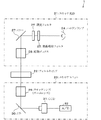
本実施の形態に係る写真焼付装置は、写真フィルムに記録されている画像を、感光材料としての印画紙上に焼き付けるものであり、図1に示すように、フィルムスキャナ1と、画像処理部(画像処理装置)2と、露光部3とを備えている。
【0094】
上記フィルムスキャナ1は、図2に示すように、写真フィルムに光を照射するスキャナ光源21と、上記写真フィルムを搬送するためのフィルムキャリア22と、スキャナ光源21から出射され、上記写真フィルムを透過する光を測光することによって上記写真フィルムに記録された画像を取り込むスキャナユニット23とで構成されている。
【0095】
上記スキャナ光源21は、光を出射するハロゲンランプ24と、熱線吸収フィルタ25と、調光フィルタ26と、ミラー27と、拡散ボックス28とを、光の進行方向に沿ってこの順で備えている。また、上記スキャナユニット23は、スキャナレンズ(ズームレンズ)29と、ミラー30と、3板式のCCD(Charge Coupled Device)31とを、光の進行方向に沿ってこの順で備えている。また、上記CCD31は、A/D(Analog to Digital)変換部32と接続されている。
【0096】
上記画像処理部2は、写真フィルムの1コマの画像を構成する各画素のR(赤),G(緑),B(青)のデジタル画像データに基づいて、上記画像のコントラストや濃度を補正する処理を行なうものである。つまり、画像処理部2は、フィルムスキャナ1から送られてきたRGBのデジタル画像データに基づいて、露光量の補正値をRGBごとに算出し、これらの情報を露光部3に送る。なお、画像処理部2の詳細な構成については後述する。
【0097】
また、上記画像処理部2は、写真焼付装置に組み込まれたマイクロプロセッサおよび/またはDSP(Digital Signal Processor)などによって構成されてもよいし、装置の外部に設けられたPC(Personal Computer)によって構成されてもよい。また、画像処理部2は、フィルムスキャナ1からの画像データを一時的に格納するメモリ(図示せず)を備えている。
【0098】
上記露光部3は、画像処理部2にて補正されたRGBのデジタル画像データに基づいて光変調素子の各画素を駆動することにより、印画紙を露光するものである。上記の光変調素子としては、例えばPLZT露光ヘッド、DMD(デジタル・マイクロミラー・デバイス)、LCD(液晶表示装置)、LCS(液晶シャッタ)、LEDパネル、レーザー、FOCRT(Fiber Optic Cathode Ray Tube)、CRTが挙げられる。
【0099】
次に、本発明の特徴である画像処理部2について説明する。上記画像処理部2は、図1に示すように、濃度補正部11、領域設定部(領域判別手段)12、ぼかしマスク作成部(ぼかしマスク画像作成手段)13、ノイズ・粒状感抑制強度算出部(強度算出手段)14、ノイズ・粒状感抑制フィルタ生成部(フィルタ生成手段)15、ノイズ・粒状感抑制処理部(第1の処理手段)16、および、補正演算処理部17から構成される。
【0100】
また、上記ノイズ・粒状感抑制強度算出部(強度算出手段)14とノイズ・粒状感抑制フィルタ生成部(フィルタ生成手段)15とで行なわれる処理をあわせて一フィルタ処理と捉えた場合、この一フィルタを設定する部をフィルタ設定部(フィルタ設定手段)と称する。
【0101】
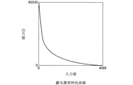
上記濃度補正部11は、フィルムスキャナ1から送られるRGBの画像データを、用いた写真フィルムの感度特性に応じた画像データに補正するためのブロックである。より具体的には、濃度補正部11は、図3に示すような、フィルムの種類に応じて予め定められた入力値と出力値との関係を示す露光濃度特性曲線を用いてフィルムスキャナ1からの入力値を出力値に変換する。
【0102】
上記領域設定部12は、上記濃度補正部11の出力値を基に、R,G,Bの画像データから構成される1コマの画像において、露光不足の領域をアンダー露光領域と設定し、露光過多の領域をオーバー露光領域と設定するブロックである。以下、上記領域設定部12において実行される手順を具体的に説明する。
【0103】
ここで、R,G,Bごとにアンダー露光と判断する画像データが、例えば閾値αと定められ、オーバー露光と判断する画像データが例えば閾値βと定められ、オーバー露光領域またはアンダー露光領域と設定される画素密度(コマ画像のうち充填されているアンダー露光画素またはオーバー露光画素の数)が例えば閾値ψと予め定められているものとし、閾値α,βおよびψは予め、ROM等(図示せず)の記憶手段に記憶されているものとする。
【0104】
まず、任意のコマにおける画像データのうち、ある画素において、各色の画像データがすべて閾値α以下の場合、その画素をアンダー露光画素と決定し、各色の画像データがすべて閾値β以上の場合、オーバー露光画素と決定する。つまり、ある画素に着目した場合、その画素のR,G,Bの画像データをそれぞれr,g,bとすると、r<α,g<α,b<αの条件を満たす場合に、その画素をアンダー露光画素と設定し、r>β,g>β,b>βの条件を満たす場合に、その画素をオーバー露光画素と決定するものである。
【0105】
さらに、任意のコマを構成する画像におけるアンダー露光画素またはオーバー露光画素について、充填されている画素の密度がψ以上の領域をアンダー露光領域またはオーバー露光領域と設定する。そして、領域設定部12は、設定されたアンダー露光領域またはオーバー露光領域に該当する画素についての情報(以下、領域情報という)をぼかしマスク作成部13へ出力する。
【0106】
なお、閾値αは、各色で同一の値に設定してもよいし、異なる値に設定してもよい。閾値βも、各色で同一の値に設定してもよいし、異なる値に設定してもよい。
【0107】
以上により、領域設定部12により、アンダー露光領域とオーバー露光領域とが判別される。
【0108】
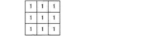
上記ぼかしマスク作成部13では、上記オーバー領域やアンダー領域の各画素に対して、移動平均フィルタ(以下、第1のフィルタと称する)を用いたフィルタ処理がされ、ぼかし画像が作成される。なお、図4に、上記移動平均フィルタの一例を示す。
【0109】
ここで、一旦ぼかし画像を作成するのは、以下の理由による。
【0110】
原画像データにおいては、通常、各画素に多くのノイズが含まれている。したがって、ノイズを含んだ画像データを用いて、後述するノイズ・粒状感抑制強度算出部14による抑制強度の算出を行なうと、適切な強度が得られなくなる。つまり、上記抑制強度は、着目画素に対してノイズ成分を除いた値を用いて設定する必要がある。
【0111】
これは、上記抑制強度を求めるための計算式が、例えば、下記の(1)式を用いて計算されるためである。この場合に、着目画素本来の画像データをa=10と、この着目画素にノイズが含まれた場合の画像データをa=5とすると、抑制強度は、それぞれにγ=55、γ=155となる。すなわち、抑制強度の値が、両者間で100も相違してしまい、ノイズの影響を受けると適正な処理が行えなくなる。このため、上記ぼかしマスク作成部13では、一旦ぼかし画像を作成し、できる限りノイズ成分の除去を図っている。
【0112】
γ=−20×a+255 ・・・ (1)
なお、上記ぼかし画像の作成は、必ず行なわなくてはならない処理ではない。つまり、ぼかしマスク作成部13は、本願発明にとっての必須の構成要件ではない。ただし、このぼかしマスク作成部13でぼかし画像を作成することにより、より高品位な画像を得ることができる。
【0113】
次に、上記ノイズ・粒状感抑制強度算出部14では、上記ぼかしマスク作成部13で作成された画像の各画素の画像データに応じた抑制強度P(抑制強度の値)が設定される。すなわち、このノイズ・粒状感抑制強度算出部14は、詳細については後述するが、上記領域設定部12により得られたオーバー領域やアンダー領域に対する画素の抑制強度Pを求めるものである。
【0114】
このように、アンダー領域やオーバー領域に対して抑制強度Pを算出する理由は、上記アンダー領域やオーバー領域に対応した領域をCCDで読込んだ際にはノイズが多く発生するからである。
【0115】
つまり、上記ノイズ・粒状感抑制強度算出部14では、アンダー領域やオーバー領域における抑制強度Pを各画素の画像データに応じて変化させることにより、元の画像データの情報を極力残しつつも、十分にノイズを軽減するような値に抑制強度Pが設定される。なお、上記抑制強度は、R,G,B毎に設定されるものである。
【0116】
ここで、図5に、一例として、Rの画像データに対する抑制強度Pを示す。なお、この図の場合には、Rの画像データを216ビットで、つまり65536通り(0から65535)で示している。なお、アンダー領域やオーバー領域においても、画素毎で見ると、様々な画像データを有している。例えば、アンダー領域にも、高い画像データを有する画素が含まれている。また、オーバー領域にも、低い画像データを有する画素が含まれている。したがって、アンダー領域やオーバー領域であろうとも、取り得る画像データの範囲(図5では、0から65535までの範囲)で上記抑制強度Pを定めておく。
【0117】
上記Rの画像データが0からV1の範囲内では、抑制強度PをP1とする。また、上記画像データがV1からV2の範囲内では、画像データの上昇とともに、抑制強度がP1から一次関数的に比例して減少し、画像データがV2の地点にて抑制強度がP2となるようにする。さらに、上記画像データがV2からV3の範囲内では、画像データの上昇とともに、抑制強度がP2から一次関数的に比例して減少し、画像データがV3の地点にて抑制強度がP3となるようにする。また、上記画像データがV3からV4の範囲内では、画像データの上昇とともに、抑制強度がP3から一次関数的に比例して増加し、画像データがV4の地点にて抑制強度がP4となるようにする。そして、上記Rの画像データがV4から65535の範囲内では、抑制強度PをP4のままとする。
【0118】
なお、上記の抑制強度の設定例は、あくまで一例であって、これに限定されるものではない。画像データが低い画素や高い画素に対して、抑制強度Pを強くするように設定されているものであればよい。
【0119】
次に、上記ノイズ・粒状感抑制フィルタ生成部15では、上記アンダー領域およびオーバー領域の各画素に対して、後述するフィルタ中央値増加量ΔC(エッジ情報)の値に応じたフィルタ(以下、第2のフィルタと称する)が設定される。
【0120】
この第2のフィルタは、例えば、図6に示すとおり、3×3で示されるフィルタとすることができる。そして、この場合、第2のフィルタの中央値Cが、上記ぼかしマスク作成部13で作成された画像の画像データを利用して設定される。なお、上記図6に示す第2のフィルタでは、フィルタ中央以外の値は、全て1としている。
【0121】
このように、第2のフィルタを、中央以外の値を1とし、かつ、中央値Cを画素毎に設定する理由は、以下のとおりである。
【0122】
元の画像データにおいて、画像のエッジ部における互いに隣接する画素同士では、両画素の画像データの差が大きくなる。とりわけ、エッジ部分が鮮鋭な画像の場合には、上記画像データの差が大きくなる。
【0123】
ところで、後述するノイズ・粒状感抑制処理部16では、アンダー領域およびオーバー領域内で、原画像に対してノイズ・粒状抑制処理がなされる。つまり、原画像に対して、ぼかし処理が行われることになる。
【0124】
それゆえ、エッジ部を考慮せずに上記ノイズ・粒状抑制処理を行なうと、隣接画素間の画像データの差が小さくなり、エッジの鮮鋭度が低い画像となってしまう。したがって、エッジ部の画素に関しては、上記ノイズ・粒状感抑制処理部16における処理にて、エッジ部の画素の影響が強く出て、かつ、ぼかし処理が行なえるようなフィルタを用いる必要がある。
【0125】
一方、非エッジ部に対しては、この非エッジ部の画素を全体的にぼかすことが必要である。つまり、アンダー領域やオーバー領域では、とりわけ粒状性が目立つため、非エッジ部に関しては、十分なぼかし処理を行なう必要がある。
【0126】
このため、上述したとおり、第2のフィルタは、その中央以外の値を1とし、かつ、中央値Cを画素毎に設定することとしている。以下において、上記中央値Cの具体的な設定の仕方について説明する。なお、この中央値Cについても、R,G,B毎に設定されるものである。
【0127】
まず、フィルタ中央値増加量ΔCを求める。このフィルタ中央値増加量ΔCは、フィルタの中央値Cを、1からどの程度増加させればよいかを示す量(値)である。つまり、フィルタの中央値Cは、以下の式(2)により示される。なお、このフィルタ中央値増加量ΔCについても、R,G,B毎に設定される。
【0128】
C=1+ΔC ・・・ (2)
上記フィルタ中央値増加量ΔCは、着目画素(つまり、画像処理しようと着目している画素)の画像データと、この着目画素に隣接する8つの画素の画像データとを用いて求められる。具体的に説明すると、図7に示すとおり、縦横3×3の画素をそれぞれQ1からQ9とし、Q1からQ9に対応する画像データをq1からq9とした場合、以下の式(3)により計算される。
【0129】
なお、中央のQ5が着目画素であり、Q1とQ9と、Q2とQ8と、Q3とQ7と、およびQ4とQ6とが、それぞれにQ5を挟んで相対している。また、Q2はQ1とQ3とに挟まれており、Q8はQ7とQ9とに挟まれている。さらに、Q1の右隣の画素をQ2とする。なお、以下の式(3)のKcは、詳細については後述するが、フィルタ中央値強度係数である。
【0130】
ΔC=Kc×10×{(|q2−q8|+|q4−q6|+|q1−q9|+|q3−q7|)/3+(|(q2+q8)−(q4+q6)|+|(q1+q9)−(q3+q7)|)/2}/(65535−0) ・・・ (3)
上記の式(3)を用いてフィルタ中央値増加量ΔCを算出する理由は、上記フィルタ中央値増加量ΔC(エッジ情報)が、フィルタ中央値強度係数Kcを定数とした場合、着目画素がエッジ部を構成する画素であれば値が大きくなり、エッジ部を構成しない画素であれば値が小さくなるという特性を有するためである。より詳しくは、原画像において、エッジが鮮鋭であればあるほど、上記フィルタ中央値増加量ΔCの値はより大きくなり、エッジが鮮鋭でない箇所ほど、上記値はより小さくなるという特性を有するためである。
【0131】
なお、上記フィルタ中央値増加量ΔCや、下記の式(4)で示されるΔC’の値を、エッジを形成する程度を示すパラメータの値と称する。ただし、これらは一例であって、これらに限定されるものではない。
【0132】
ΔC’={(|q2−q8|+|q4−q6|+|q1−q9|+|q3−q7|)/3+(|(q2+q8)−(q4+q6)|+|(q1+q9)−(q3+q7)|)/2} ・・・ (4)
この特性により、上記第2のフィルタは、上記フィルタ中央値増加量ΔC(エッジ情報)が大きい場合には、着目画素の鮮鋭化度合をエッジ情報の増加に応じて増すようなフィルタ(鮮鋭化フィルタ)としての機能を果たす一方、上記フィルタ中央値増加量ΔC(エッジ情報)が小さい場合には、エッジ情報の低下に応じて平滑化度合を増すようなフィルタ(平滑化フィルタ)の機能を果たすことになる。
【0133】
また、フィルタ中央値強度係数Kcは、フィルタ中央値増加量を制御するための変数である。このように、フィルタ中央値強度係数Kcを制御するのは、着目画素に関して、どのようなフィルタ中央値増加量ΔCに設定するのが適切かは、画像を読み取るスキャナの特性や、出力機器であるプリンタの能力等、各種さまざまな要因により異なるためである。
【0134】
なお、以下においては、説明の便宜上、フィルタ中央値強度係数Kcを一定の値に固定した際、フィルタ中央値増加量ΔCの値が所定の値以上になった場合にエッジ部を構成すると、上記所定の値以下になった場合にエッジ部を構成しないと記載する。また、エッジ部を構成する画素をエッジ部の画素と、エッジ部を構成しない画素を非エッジ部の画素と称する。
【0135】
また、ΔCの値が大きくなり、Cの値が一定値(Clim)以上になる場合には、Cの値をClimの値で制限しておく。一方、ΔCの値が小さくなり、Cの値が0以下となった場合には、Cの値を0としておく。
【0136】
本実施の形態では、以上のような第2のフィルタを設定することが最も好ましいが、上記の設定に限定されるものではない。エッジ部において、着目画素の画素情報が十分に反映され、かつ、非エッジ部において、画像の平滑化が図れるようなフィルタであればよい。
【0137】
また、例えば、ΔCの値が所定の値より小さくなり、着目画素が非エッジ部と判断できる場合には、ΔCの値を0に(つまり、C=1)固定した非エッジ部用のフィルタを別途に用いてもよい。
【0138】
以上のように、エッジ部については、非エッジ部と同様な強度でぼかし処理を行なうのではなく、ぼかしの程度を弱くしてエッジの潰れがなくなるようなフィルタを用いればよい。
【0139】
また、上記第2のフィルタや移動平均フィルタは、着目画素に対して3×3画素を参照するフィルタであるが、周囲の画素の画像データを参照した処理であれば、参照される画素数はこれに限定されない。また、上記ぼかし処理では、着目画素に隣接する周囲の画素を参照しているが、隣接していない周囲の画素についても参照することができる。
【0140】
次に、上記ノイズ・粒状感抑制処理部16では、上記領域設定部12で設定された領域の各画素に対して、上記ノイズ・粒状感抑制強度算出部14で算出された抑制強度と、上記ノイズ・粒状感抑制フィルタ生成部15で設定された中央値Cを有する第2のフィルタとを用いて、ぼかし処理が行なわれるブロックである。なお、このぼかし処理は、R,G,Bに対して、それぞれに行なわれる。
【0141】
ここで、ぼかし処理とは、例えば、ある着目画素の画像データについて、周囲の画素の画像データを参照することにより、画像にぼやけ感を生じさせる処理をいう。また、中心の1点の色に周囲の色を混ぜ合わせることにより、ぼかし効果を生じさせる処理ということもできる。
【0142】
このノイズ・粒状感抑制処理部16におけるぼかし処理では、ぼかし処理前の原画像の画像データをRin、上記Rinに対して上記第2のフィルタを用いてフィルタ処理した後の値をX1、第2のフィルタにおけるフィルタ要素値の総和(つまり、図6では、C+8)をSumF1とすると、ぼかし処理後の画像データRoutは、以下の式(5)で示される。
【0143】
Rout=Rin−{λ×(P/100)/255}×(Rin−X1/SumF1) ・・・ (5)
ただし、上記λは、上記ノイズ・粒状感抑制強度算出部14で求められる抑制強度Pを制御するための変数である。このように、変数λを用いて抑制強度Pを制御するのは、どのような抑制強度Pに設定するのが適切かは、画像を読み取るスキャナの特性や、出力機器であるプリンタの能力等、各種さまざまな要因により異なるためである。
【0144】
また、式(5)で求められたRoutが65535を超える場合には、Routを65535と、Routが0以下となる場合には、Routを0としておく。
【0145】
なお、上記の式(5)は、一例であって、この式に限定されるものではない。
【0146】
次に、上記補正演算処理部17は、用いる写真フィルムに応じた適切な明暗を印画紙上に出すためのガンマ補正を行なうブロックである。より具体的には、補正演算処理部17は、図8に示すような入力値と出力値との関係を示すガンマ曲線としての濃度特性曲線(ガンマ補正演算用LUT)を用い、濃度補正部からの入力値を出力値に変換する。なお、図8は、写真フィルムがネガフィルムの場合のガンマ曲線を示している。なお、上記ガンマ補正は、画像全体に対して行なうものとする。つまり、アンダー領域やオーバー領域以外のノーマル領域についても、ガンマ補正を行なうものとする。
【0147】
そして、上記画像処理部2(つまり、濃度補正部11、領域設定部12、ぼかしマスク作成部13、ノイズ・粒状感抑制強度算出部14、ノイズ・粒状感抑制フィルタ生成部15、ノイズ・粒状感抑制処理部16、および、補正演算処理部17)における各処理の後には、上述したように、上記露光部3で画像処理後の画像データが印画紙上に露光される。
【0148】
以上のように、本実施の形態では、上記ノイズ・粒状感抑制強度算出部14において、各画素の画像データに応じて抑制強度Pが設定され、上記上記ノイズ・粒状感抑制フィルタ生成部15において、フィルタの中央値Cの設定が行なわれる構成である。
【0149】
なお、上記の構成の代わりに、上記抑制強度Pと上記中央値Cとの両方を考慮したフィルタ(以下、他のフィルタと称する)を用いて処理を行うことも可能である。ただし、抑制強度Pとフィルタの中央値Cとを個別に設定できる構成とする方が好ましい。この理由を以下に説明する。
【0150】
まず、結果として、着目画素のぼかし度合を比較的弱くする設定、または、着目画素をぼかさない設定となるのは、着目画素がエッジ部を構成しない領域内であって、かつ、通常の露出状態(つまり、画素単位で判断した場合に適正露光)である場合(以下、第1の条件と称する)か、あるいは、着目画素がエッジ部を構成する画素である場合(以下、第2の条件と称する)かである。
【0151】
ここで、抑制強度Pとフィルタの中央値Cとを個別に設定できない場合には、上記第1の条件あるいは第2の条件のどちらかの条件によって、着目画素をぼかさないようなフィルタの設定となっているのかが判断できない。
【0152】
そのため、抑制強度Pとフィルタの中央値Cとを個別に設定できるようにして画像処理用のパラメータを増やし、このパラメータを個別に設定することにより、処理後画像の出力結果について調整容易としている。
【0153】
次に、上記構成の画像処理部2を備えた写真焼付装置におけるデジタル画像データの処理手順を図9のフローチャートに基づいて説明する。なお、ここでは、写真フィルムとして、ネガフィルムを用いているがポジフィルムであっても構わない。また、以下の説明では、写真フィルムにおける任意の1コマにおける画像処理の手順について説明することになる。
【0154】
まず、図2に示したフィルムキャリア22にて、写真フィルムの任意のコマが支持されると、ハロゲンランプ24から出射された光は、熱線吸収フィルタ25にて熱線成分が除去されて調光フィルタ26に入射し、調光フィルタ26にて調光された後、ミラー27にて進行方向が変えられて拡散ボックス28に入射する。拡散ボックス28では、入射光がむらのない光に拡散され、この光がフィルムキャリア22にて支持されている写真フィルムの任意のコマに照射される(S1)。
【0155】
なお、フィルムスキャナ1にて得られる画像データは、写真フィルムに元々含まれる情報よりも取り得る値の範囲が狭いものとなっている。写真フィルムに含まれる情報は、例えば、0(黒)〜255(白)までの8ビットのデータ、0(黒)〜4095(白)までの12ビットのデータ、0(黒)〜65535(白)までの16ビットのデータなどを考えることができる。
【0156】
そして、写真フィルムを透過した光は、スキャナレンズ29にて、ミラー30を介してCCD31の受光面に入射できるような光に変換された後、ミラー30にて進行方向を変えられてCCD31の受光面に入射する。これにより、CCD31は、写真フィルムの任意のコマにおけるアナログ画像データ(アナログの電気信号)を取得できる(S2)。
【0157】
そして、CCD31は、各画素での受光量に応じたアナログ画像データをRGBごとにA/D変換部32に送る。さらに、これらのアナログ画像データは、A/D変換部32にてデジタル画像データ(デジタルの電気信号)に変換される(S3)。
【0158】
このようにして、写真フィルムに記録されている画像の各画素のデジタル画像データがR,G,Bごとに得られることになる。これらのデジタル画像データは、画像処理部2の濃度補正部11へ送られる。そして、このようにして読み取られたデジタル画像データが濃度補正部11に入力されると、濃度補正部11は、例えば図3に示した露光濃度特性曲線を用いて、R,G,Bの入力画像データを出力画像データに変換する(S4)。これにより、フィルムスキャナ1にて得られる画像データの明暗と、用いる写真フィルムに記録された画像の明暗とを合わせることができる。なお、濃度補正部11では、図3に示すとおり、12ビットの入力値を16ビットの出力値に変換しているが、入力値および出力値はこのビット数に限定されるわけではない。
【0159】
また、写真フィルムに含まれる画像データ情報は、0から255までの256階調(8ビット)や、0から4095までの4096階調(12ビット)であってもよい。いずれの場合でも、値が小さいほど濃度が濃く、値が大きいほど濃度が薄いことを示している。また、0〜65535までの画像データ情報のどこを0とし、どこを65535とするのかは、図示しない入力部からの入力により設定されてもよいし、デフォルトで自動的に設定されるようにしてもよい。
【0160】
さらに、濃度補正部11によって変換処理がなされたデジタル画像データは、領域設定部12へ送られる。この領域設定部12では、上述したとおり、上記変換処理がなされたデジタル画像データから、写真フィルムの任意の1コマにおけるアンダー露光領域とオーバー露光領域とが設定される(S5)。
【0161】
次に、ぼかしマスク作成部13では、上述したように、アンダー領域およびオーバー領域の画像に対してマスクが作成される(S6)。この後、ノイズ・粒状感抑制強度算出部14にて、アンダー領域およびオーバー領域の各画像に対する抑制強度Pが算出される(S7)。ノイズ抑制強度が算出された後は、ノイズ・粒状感抑制フィルタ生成部15にて、アンダー領域およびオーバー領域に関し、上記第2のフィルタが画素毎対応して生成される(S8)。
【0162】
上記第2のフィルタが設定された後は、上記ノイズ・粒状感抑制処理部16にて、任意のコマ画像を構成する画素のうち、上記領域情報に基づいて設定されたアンダー露光領域やオーバー露光領域に該当する画素に対して、上記ノイズ・粒状感抑制強度算出部14にて設定された強度と、ノイズ・粒状感抑制フィルタ生成部15で設定した第2のフィルタを用いて、ノイズ・粒状感抑制処理が施される(S9)。
【0163】
上記ノイズ・粒状感抑制処理の後は、補正演算処理部17にて、画像全体に対してガンマ補正が行なわれる(S10)。そして、ガンマ補正が行なわれた後に、一連の画像処理後のデジタル画像に基づいて、露光部3により印画紙に画像を焼き付けることにより、任意のコマにおける画像を印画紙上に再現することができる(S11)。
【0164】
なお、上記の手順では、S7において抑制強度Pが算出された後、S8において、エッジ部および非エッジ部の各部に対応したフィルタが設定されたが、これに限定されるものではない。例えば、上記フィルタを設定した後に、上記抑制強度を算出する手順としてもよい。
【0165】
以上のように、本実施の形態の画像処理装置では、上記領域設定部12にて、粒状性が目立ち易く、かつ、ノイズの影響を被り易い、アンダー露光領域およびオーバー露光領域を予め判別し、この領域のみを画像処理の対象とすることにより、画像全体に対して画像処理するよりも画像処理対象の領域が狭くなり、画像処理に要する時間を短縮することができる。
【0166】
また、上述したように、上記フィルタ設定部(ノイズ・粒状感抑制強度算出部14およびノイズ粒状感抑制フィルタ生成部15)により、エッジを形成する程度を示すパラメータの値に応じて、ぼかしマスク作成部13で得られた画像に対して画像処理に用いられるフィルタを、鮮鋭化を図ったフィルタとしたり、あるいは、平滑化を図るフィルタとしたりすることができる。
【0167】
また、ノイズ・粒状感抑制処理部16においては、上記フィルタ設定部で設定されたフィルタを用いて、前記アンダー露光領域およびオーバー露光領域の各画素の画像処理が行なわれる。
【0168】
それゆえ、エッジ部については鮮鋭度を保ちつつ、エッジ部以外においては、粒状感とノイズとの影響を抑制することが可能となる。
【0169】
以上より、画像の鮮鋭度を保ったまま、高速な処理にてノイズや粒状感を抑制できる画像処理装置を提供することが可能となる。
【0170】
また、上記の説明においては、エッジを形成する程度を示すパラメータの値に応じて、ぼかしマスク作成部13で得られた画像に対して画像処理に用いられるフィルタを、鮮鋭化を図ったフィルタとしたり、あるいは、平滑化を図るフィルタとしたりしたが、このフィルタの設定を以下のようにもできる。
【0171】
つまり、上記フィルタ設定手段(ノイズ・粒状感抑制強度算出部14およびノイズ・粒状感抑制フィルタ生成部15)が、前記アンダー露光領域およびオーバー露光領域の各画素に関し、エッジを構成する画素か否かに応じて、各画素の画像処理に用いるフィルタを別々に設定するようにしてもよい。すなわち、エッジを構成する場合(例えば、上記フィルタ中央値増加量ΔCの値が所定の値以上になった場合)には、一つの鮮鋭化を図るフィルタを設定し、エッジを構成しない場合(上記フィルタ中央値増加量ΔCの値が所定の値以下になった場合)には、一つの平滑化を図るフィルタを設定する構成としてもよい。
【0172】
また、エッジを形成する程度を示すパラメータの値を、複数の区分に分類して、それぞれの区分で異なるフィルタを設定する構成としてもよい。例えば、上記区分を4つとし、パラメータの値の採り得る範囲を0から100とする。また、第1区分の範囲を0以上25未満、第2区分の範囲を25以上50未満と、第3区分の範囲を50以上から75未満と、第4区分の範囲を75以上から100以下とする。この場合、
第1区分では平滑化強度の強い一フィルタを、第2区分では平滑化強度の弱い一フィルタを、第3区分では鮮鋭化強度の弱い一フィルタを、第4区分では鮮鋭化強度の強い一フィルタを設定すればよい。
【0173】
〔実施の形態2〕
本発明の他の実施の形態について、図10から図12に基づいて説明すれば、以下のとおりである。なお、説明の便宜上、前記実施の形態1の図面に示した部材と同一の機能を有する部材については、同一の符号を付し、その説明を省略する。
【0174】
本実施の形態に係る写真焼付装置は、写真フィルムに記録されている画像を、感光材料としての印画紙上に焼き付けるものであり、図10に示すように、フィルムスキャナ1と、画像処理部(画像処理装置)2’と、露光部3とを備えている。
【0175】
上記画像処理部2’は、上記実施の形態1の画像処理部2と同様に、写真フィルムの1コマの画像を構成する各画素のR(赤),G(緑),B(青)のデジタル画像データに基づいて、上記画像のコントラストや濃度を補正する処理を行なうものである。つまり、画像処理部2’は、フィルムスキャナ1から送られてきたRGBのデジタル画像データに基づいて、露光量の補正値をRGBごとに算出し、これらの情報を露光部3に送る。
【0176】
なお、上記画像処理部2’は、写真焼付装置に組み込まれたマイクロプロセッサおよび/またはDSP(Digital Signal Processor)などによって構成されてもよいし、装置の外部に設けられたPC(Personal Computer)によって構成されてもよい。また、画像処理部2’は、フィルムスキャナ1からの画像データを一時的に格納するメモリ(図示せず)を備えている。
【0177】
また、上記画像処理部2’は、図10に示すように、濃度補正部11、領域設定部(領域判別手段)12’、低周波画像作成部(低周波画像データ抽出手段)41、高周波画像作成部(高周波画像データ抽出手段)42、ノイズ除去部(ノイズ除去手段)43、画像重ね合せ部(画像重ね合わせ手段)44、ノイズ・粒状感抑制処理部(第2の処理手段)45、および、補正演算処理部17から構成される。
【0178】
上記領域設定部12’は、設定されたアンダー露光領域またはオーバー露光領域に該当する画素についての情報(以下、領域情報という)を、上記実施の形態1におけるぼかしマスク作成部13に出力する代わりに、低周波画像作成部41と高周波画像作成部42とへ出力する点を除けば、他の機能は上記実施の形態1の領域設定部12と同じである。
【0179】
次に、上記低周波画像作成部41では、まず、濃度補正部11で処理された画像の各画素の輝度データを基にしてモザイク画像が作成される。なお、このモザイク画像は、原画像データの輝度データに対して加算平均処理を行うことにより作成される。また、モザイク画像とは、ぼかし画像の一種である。本実施の形態では、モザイク画像を用いて説明するが、これに限定されず、ぼかし画像であればよい。
【0180】
そして、次に、上記モザイク画像に対して、縦横n×nのサイズのガウシアンフィルタによるフィルタ処理が2回行なわれる。なお、上記のように、ガウシアンフィルタによるフィルタ処理を2回行なうのは、本フィルタ処理の手法をハードにより実現する際に、処理の高速化を図れるからである。
【0181】
つまり、フィルタ処理を1回しか行わない場合には、ガウシアンフィルタの一辺のサイズを2倍のサイズ、面積で考えると4倍のサイズとしなければならず、高速化を図れない。それゆえ、上記のようにフィルタ処理を2回行うこととしている。ただし、高速化が特段必要とされない場合には、1回のフィルタ処理で済ませることも可能である。図11に、上記ガウシアンフィルタの一例を示す。
【0182】
また、ガウシアンフィルタ処理後には、処理後の出力値X2に対して、予め設定されたフィルタ強度Tにより、出力値の重み付けがなされる。
【0183】
ここで、原画像の輝度データをD、ガウシアンフィルタにおけるフィルタ要素値の総和をSumF2とすると、上記一連の処理後の輝度データD’は、例えば、以下の式(6)で示される値となる。
【0184】
D’=D+(X2/SumF2−D)×T/128 ・・・ (6)
なお、上記の原画像データにおける着目画素の輝度データDと、この着目画素の周囲の画素であって、着目画素のガウシアンフィルタ処理に用いられる画素(以下、演算対象画素と称する)の輝度データとの差が、一定値以上ある場合には、この演算対象画素の輝度データを補正した補正値を用いてガウシアンフィルタ処理を行なう。この補正は、より詳しくは、演算対象画素の輝度データが、着目画素の輝度データから一定値以上離れている場合に、演算対象画素の輝度データを着目画素から一定値だけ離れた輝度データとするものである。
【0185】
例えば、上記一定値が8000、着目画素の輝度データが32000、演算対象画素の輝度データが42000である場合には、上記補正により演算対象画素の輝度データの補正値は40000(32000+8000)となる。また、上記演算対象画素の輝度データが20000である場合には、上記補正により補正値は24000(32000−8000)となる。
【0186】
以上のように、演算対象画素の輝度データを一旦補正してガウシアンフィルタ処理を行なうのは、この演算対象画素が、低周波画像に含まれる画素ではなく、高周波画像に含まれるべき画素であるためである。
【0187】
次に、上記高周波画像作成部42では、原画像データから、上記低周波画像作成部41で作成された低周波画像の画像データを差し引くことにより、高周波成分からなる高周波画像が作成される。
【0188】
ここで、高周波成分は、着目画素と、該着目画素と隣合う隣接画素との輝度データの差で表現される。したがって、隣接する画素との輝度データの差が非常に大きくなるような着目画素は、エッジ部の画素であるか、あるいは、エッジ部の画素ではなくて、単にノイズ成分を多く含んだ画素であると判断できる。
【0189】
また、着目画素がエッジ部を構成する画素の場合には、この着目画素の周囲の各画素との輝度データの差を考えると、周囲の各画素のうち、ある一方向(例えば、実施の形態1の図7に示したQ2からQ8の方向)の画素(図7では、Q2およびQ8)との輝度データの差が大きくなる一方、上記一方向と直角方向(図7では、Q4からQ6の方向)の画素(図7では、Q4およびQ6)との輝度データの差が小さくなる。さらに、着目画素がエッジ部を構成する画素の場合には、着目画素を輝度データの差が少ない画素の方向に移動させて、上記と同様に輝度データの差を求めた際に、上述した関係が成立する。
【0190】
一方、着目画素がノイズ成分を多く含んだ画素であって、エッジ部を構成する画素でない場合には、輝度データの差が大きい方向と小さい方向との関係が、基本的に、上記着目画素がエッジ部を構成する場合のような関係にはならない。例え、ある着目画素における、輝度データの差が大きい方向と小さい方向との関係が、上記着目画素がエッジ部を構成する場合のような関係となったとしても、輝度データの差が少ない画素の方向に着目画素を移動させて上記と同様に輝度データの差を求めた場合に、上述した関係(つまり、上記着目画素がエッジ部を構成する場合に成立する際の、輝度データの差が大きい方向と小さい方向との関係)が成立しない。
【0191】
以上の性質により、着目画素がエッジ部を構成する画素であるか、あるいは、エッジ部を構成するのではなくて、単にノイズを多く含んだ画素(以下、ノイズを多く含んだ画素と称する)であるかが判別できる。それゆえ、高周波画像から、エッジ部の画素あるいはノイズを多く含んだ画素を抽出することが可能となる。
【0192】
また、別の方法として、高周波画像に対してフーリエ変換を用い、高周波画像からノイズ成分を除去することも可能である。
【0193】
これは、高周波画像に対してフーリエ変換を行なうと、エッジ部を構成する画素を表す信号の周波数は、各画素ともに規則的な分布となる一方、高周波画像のノイズ成分を表す信号の周波数は、極端に狭い帯域に集中するからである。これにより、ノイズ成分が特定でき、ノイズ成分を除去することが可能となる。
【0194】
そして、上記ノイズ除去部43では、高周波画像において、ノイズを多く含んだ画素からノイズ成分が取り除かれる。これにより、エッジ部を構成する画素のエッジ情報をそのまま有するとともに、ノイズ成分が除去された高周波画像が得られる。
【0195】
上記画像重ね合せ部44では、上記低周波画像作成部41で作成された低周波画像と、上記ノイズ除去部43で得られる、ノイズ画素が除去された画像(つまり、エッジ部を構成する画素からなる画像)とが重ね合わされる。
【0196】
なお、上記重ね合わせに関しては、上記のように単に重ね合せるだけでもよいし、階調変換処理を施した後に重ね合せてもよい。
【0197】
上記ノイズ・粒状感抑制処理部45では、上記画像重ね合せ44で重ね合わされた画像の画像データを用いて、原画像データのノイズ・粒状抑制処理がなされる。より詳しくは、上記濃度補正部11で補正された原画像データのうち、アンダー領域およびオーバー領域の画像データが、新たに画像重ね合せ部44で重ね合せされた画像データに補正される。
【0198】
そして、上記露光部3により、露光処理がなされる。
【0199】
また、上記低周波画像作成部41、高周波画像作成部42では、輝度データを基にして、低周波画像や高周波画像を作成したが、これに限定されるものではなく、画像データを基にして、低周波画像や高周波画像を作成することもできる。
【0200】
次に、上記構成の画像処理部2’を備えた写真焼付装置におけるデジタル画像データの処理手順を図12のフローチャートに基づいて説明する。なお、上記実施の形態1と同様に、写真フィルムとして、ネガフィルムを用いているがポジフィルムであっても構わない。また、以下の説明では、写真フィルムにおける任意の1コマにおける画像処理の手順について説明することになる。
【0201】
まず、S21から順にS24までの処理が行われる。ここで、S21からS24は、上記実施の形態1におけるS1からS4とそれぞれ同一の処理であるため、本実施の形態ではその説明を省略し、S25以降の処理について説明する。
【0202】
S24の後、上記濃度補正部11によって変換処理がなされたデジタル画像データは、領域設定部12’へ送られる。この領域設定部12’は、上述したとおり、上記変換処理がなされたデジタル画像データから、写真フィルムの任意の1コマにおけるアンダー露光領域とオーバー露光領域とを設定する(S25)。
【0203】
次に、上記低周波画像作成部41にて、上述したように、アンダー領域およびオーバー領域の画像に対して低周波画像が作成される(S26)。そして、高周波画像作成部42にて、濃度補正部11での処理後の原画像データから低周波画像の画像データを差し引くことにより、高周波画像が作成される(S27)。
【0204】
その後、上記ノイズ除去部43にて、上記高周波画像からノイズ成分が除去される(S28)。そして、上記画像重ね合せ部44にて、上記低周波画像と、ノイズ成分が除去された高周波画像とが重ね合わされる(S29)。
【0205】
次に、ノイズ・粒状感抑制処理部45にて、画像重ね合せ部44で重ね合わされた画像の画像データを用い、濃度補正部11での処理後の原画像データに対して、ノイズ・粒状感抑制処理が行われる(S30)。
【0206】
上記ノイズ・粒状感抑制処理の後は、補正演算処理部17にて、画像全体に対してガンマ補正が行なわれる(S31)。そして、ガンマ補正が行なわれた後に、一連の画像処理後のデジタル画像に基づいて、露光部3により印画紙に画像を焼き付けることにより、任意のコマにおける画像を印画紙上に再現することができる(S32)。
【0207】
本実施の形態の画像処理装置では、上記領域設定部12’にて、粒状性が目立ち易く、かつ、ノイズの影響を被り易い、アンダー露光領域およびオーバー露光領域を予め判別し、この領域のみを画像処理の対象とすることにより、画像全体に対して画像処理するよりも画像処理対象の領域が狭くなり、画像処理に要する時間を短縮することができる。
【0208】
また、上記低周波画像作成部41において、前記原画像データに対してぼかし処理を行なって得られた画像データから、低周波画像データを作成(抽出)することにより、低周波画像データを、粒状感が抑制された画像データとすることができる。
【0209】
一方、高周波画像データについては、ノイズ除去部43により、上記高周波画像データからノイズ成分が除去されることにより、高周波画像データにはエッジ部を構成する画素の画像データのみを残すことができる。
【0210】
さらに、画像重ね合せ部44にて、上記粒状感が抑制された低周波画像データと、エッジ部を構成する画素の画像データからなる高周波画像データとを重ね合せることにより、ノイズ成分が除去された画像データが得られる。
【0211】
ここで、ノイズ・粒状感抑制処理部45において、上記アンダー露光領域およびオーバー露光領域に関し、原画像の画像データを、前記重ね合わせ画像の画像データに補正する画像処理を行なうことにより、エッジ部については鮮鋭度を保ちつつ、エッジ部以外においては、粒状感とノイズとの影響を抑制することが可能となる。
【0212】
以上より、画像の鮮鋭度を保ったまま、高速な処理にてノイズや粒状感を抑制できる画像処理装置を提供することが可能となる。
【0213】
ここで、上記実施の形態1の画像処理装置と、実施の形態2の画像処理装置とは、上述したとおり、画像の鮮鋭度を保ったまま、高速な処理にてノイズや粒状感を抑制可能な装置であるが、ノイズ成分の除去という点では、実施の形態2の画像処理装置の方が、実施の形態1の画像処理装置よりも高い処理能力が得られるといえる。また、ハードウェアやソフトウェアにて、上記画像処理装置で行われる機能を実現する場合、処理速度や容易さの点では、実施の形態1の画像処理装置の方が、実施の形態2の画像処理装置よりも優れているといえる。
【0214】
ところで、以上の実施の形態1および2で説明した処理は、プログラムで実現することが可能である。このプログラムはコンピュータで読み取り可能な記録媒体に格納されている。本発明では、この記録媒体として、画像処理部2で処理が行われるために必要な図示していないメモリ(例えばROMそのもの)であってもよいし、また図示していないが外部記憶装置としてプログラム読み取り装置が設けられ、そこに記録媒体を挿入することで読み取り可能なプログラムメディアであっても構わない。
【0215】
上記いずれの場合においても、格納されているプログラムはマイクロプロセッサ(図示せず)のアクセスにより実行される構成であってもよいし、格納されているプログラムを読み出し、読み出したプログラムを図示されていないプログラム記憶エリアにダウンロードすることにより、そのプログラムが実行される構成であってもよい。この場合、ダウンロード用のプログラムは予め本体装置に格納されているものとする。
【0216】
ここで、上記プログラムメディアは、本体と分離可能に構成される記録媒体であり、磁気テープやカセットテープ等のテープ系、フロッピー(登録商標)ディスクやハードディスク等の磁気ディスクやCD−ROM/MO/MD/DVD等の光ディスクのディスク系、ICカード(メモリーカードを含む)/光カードのカード系、あるいはマスクROM、EPROM、フラッシュROM等による半導体メモリを含めた固定的にプログラムを担持する媒体であってもよい。
【0217】
最後に、上述した実施の形態1および2は、本発明の範囲を限定するものではなく、本発明の範囲内で種々の変更が可能である。
【0218】
【発明の効果】
本発明の画像処理装置は、以上のように、前記原画像中のアンダー露光領域およびオーバー露光領域を判別する領域判別手段と、前記アンダー露光領域およびオーバー露光領域の各画素に関し、エッジを形成する程度を示すパラメータの値に応じて、各画素の画像処理に用いるフィルタを設定するフィルタ設定手段と、前記フィルタを用いて、前記アンダー露光領域およびオーバー露光領域の各画素の画像データの補正を行なう第1の処理手段とを備えるものである。
【0219】
したがって、画像全体に対して画像処理するよりも画像処理対象の領域が狭くなり、画像処理に要する時間を短縮することができる。また、エッジ部については鮮鋭度を保ちつつ、エッジ部以外においては、粒状感とノイズとの影響を抑制することが可能となる。
【0220】
それゆえ、画像の鮮鋭度を保ったまま、高速な処理にてノイズや粒状感を抑制できる画像処理装置を提供することが可能となるという効果を奏する。
【0221】
また、本発明の画像処理装置は、上記の画像処理装置において、前記フィルタ設定手段は、エッジを形成する程度を示すパラメータの値が大きくなれば、鮮鋭化を図るフィルタを設定し、パラメータの値が小さくなれば、平滑化を図るフィルタを設定するものである。
【0222】
それゆえ、エッジを形成しない画素に対しては、ぼかし処理が行われる一方、エッジを形成する画素に対しては、鮮鋭化処理を行なうことが可能となるという効果を奏する。
【0223】
また、本発明の画像処理装置は、上記の画像処理装置において、前記フィルタ設定手段は、各画素の画像データに応じた画像処理強度を算出する強度算出手段と、フィルタ係数の中央値を、エッジを形成する程度を示すパラメータの値に応じて変化させるとともに、前記中央値以外の係数を一定値とするフィルタ生成手段とを含むものである。
【0224】
それゆえ、処理後画像の出力結果について、どちらのパラメータ(画像処理強度、第2のフィルタの中央値)を調整すれば所望とする画像が得られるかが判断でき、出力画像の調整が容易となるという効果を奏する。
【0225】
また、本発明の画像処理装置は、上記の画像処理装置において、さらに、原画像の画像データに対してぼかしマスク画像を作成するぼかしマスク画像作成手段を備えるものである。
【0226】
したがって、上記画像処理強度を求まる前に、一旦ぼかしマスク画像を作成して、ノイズを除去しておくことにより、最適な画像処理強度を得ることが可能となる。それゆえ、高品位な出力画像を得ることができるという効果を奏する。
【0227】
本発明の画像処理装置は、以上のように、前記原画像中のアンダー露光領域およびオーバー露光領域を判別する領域判別手段と、前記アンダー露光領域およびオーバー露光領域に関し、前記原画像データに対してぼかし処理を行なって得られた画像データから、低周波成分からなる低周波画像データを抽出する低周波画像データ抽出手段と、前記アンダー露光領域およびオーバー露光領域に関し、原画像データに含まれる高周波成分からなる高周波画像データを、原画像データから抽出する高周波画像データ抽出手段と、前記高周波画像データからノイズ成分を除去するノイズ除去手段と、前記低周波画像データと、ノイズ成分を除去した高周波画像データとを重ね合わせて、重ね合わせ画像データを作成する画像重ね合わせ手段と、アンダー露光領域およびオーバー露光領域に関し、原画像の画像データを、前記重ね合わせ画像データに補正する第2の処理手段とを備えるものである。
【0228】
したがって、画像全体に対して画像処理するよりも画像処理対象の領域が狭くなり、画像処理に要する時間を短縮することができる。また、エッジ部については鮮鋭度を保ちつつ、エッジ部以外においては、粒状感とノイズとの影響を抑制することが可能となる。
【0229】
それゆえ、画像の鮮鋭度を保ったまま、高速な処理にてノイズや粒状感を抑制できる画像処理装置を提供することが可能となるという効果を奏する。
【0230】
また、本発明の画像処理装置は、上記の画像処理装置において、前記高周波画像データ抽出手段は、前記原画像の画像データから前記低周波画像データを差し引くことにより高周波画像データを抽出するものである。
【0231】
それゆえ、複雑な画像処理を行なうことなく、高周波画像データを得ることができるという効果を奏する。
【0232】
また、本発明の画像処理装置は、上記の画像処理装置において、前記領域判定手段では、各画素の各色の画像データが、閾値αより小さい画素をアンダー露光画素とし、閾値βより大きい画素をオーバー露光画素とした場合、原画像について、充填されているアンダー露光画素の密度が閾値ψより多い領域をアンダー露光領域と、充填されているオーバー露光画素の密度が閾値ψより多い領域をオーバー露光領域と判定するものである。
【0233】
それゆえ、適正露光がなされている領域と、アンダー露光がなされている領域と、オーバー露光がなされている領域とを区別することができるという効果を奏する。
【0234】
本発明の画像処理方法は、以上のように、前記原画像中のアンダー露光領域およびオーバー露光領域を判別する第1のステップと、前記アンダー露光領域およびオーバー露光領域の各画素に関し、エッジを形成する程度を示すパラメータの値に応じて、各画素の画像処理に用いるフィルタを設定する第2のステップと、前記フィルタを用いて、前記アンダー露光領域およびオーバー露光領域の各画素の画像データの補正を行なう第3のステップとを備える方法である。
【0235】
したがって、画像全体に対して画像処理するよりも画像処理対象の領域が狭くなり、画像処理に要する時間を短縮することができる。また、エッジ部については鮮鋭度を保ちつつ、エッジ部以外においては、粒状感とノイズとの影響を抑制することが可能となる。
【0236】
それゆえ、画像の鮮鋭度を保ったまま、高速な処理にてノイズや粒状感を抑制できる画像処理方法を提供することが可能となるという効果を奏する。
【0237】
本発明の画像処理方法は、以上のように、前記原画像中のアンダー露光領域およびオーバー露光領域を判別する第1のステップと、前記アンダー露光領域およびオーバー露光領域に関し、前記原画像データに対してぼかし処理を行なって得られた画像データから、低周波成分からなる低周波画像データを抽出する第2のステップと、前記アンダー露光領域およびオーバー露光領域に関し、原画像データに含まれる高周波成分からなる高周波画像データを、原画像データから抽出する第3のステップと、前記高周波画像データからノイズ成分を除去する第4のステップと、前記低周波画像データと、ノイズ成分を除去した高周波画像データとを重ね合わせて、重ね合わせ画像を作成する第5のステップと、アンダー露光領域およびオーバー露光領域に関し、原画像の画像データを、前記重ね合わせ画像データに補正する第6のステップとを備える方法である。
【0238】
したがって、画像全体に対して画像処理するよりも画像処理対象の領域が狭くなり、画像処理に要する時間を短縮することができる。また、エッジ部については鮮鋭度を保ちつつ、エッジ部以外においては、粒状感とノイズとの影響を抑制することが可能となる。
【0239】
それゆえ、画像の鮮鋭度を保ったまま、高速な処理にてノイズや粒状感を抑制できる画像処理方法を提供することが可能となるという効果を奏する。
【0240】
また、本発明に係る画像処理プログラムは、上記画像処理装置としてコンピュータを機能させるためのものである。
【0241】
上記プログラムをコンピュータシステムにロードすることによって、上記画像処理装置をユーザに提供することが可能となる。
【0242】
また、本発明に係る画像処理プログラムは、上記の画像処理方法をコンピュータに実行させるためのものである。
【0243】
上記プログラムをコンピュータシステムにロードすることによって、上記画像処理方法をユーザに提供することが可能となる。
【0244】
また、本発明に係る画像処理プログラムを記録した記録媒体は、上記画像処理プログラムを記録しているものである。
【0245】
上記記録媒体に記録されている画像処理プログラムをコンピュータシステムにロードすることによって、上記画像処理装置または画像処理方法をユーザに提供することが可能となる。
【図面の簡単な説明】
【図1】図1は、本実施の一形態に係る画像処理装置を備えた写真焼付装置のブロック図である。
【図2】図2は、フィルムスキャナのブロック図である。
【図3】図3は、露光濃度特性曲線を示すグラフである。
【図4】図4は、移動平均フィルタのフィルタ行列を示した説明図である。
【図5】図5は、画像データと抑制強度との関係を示すグラフである。
【図6】本実施の形態に係る第2のフィルタのフィルタ行列を示した説明図である。
【図7】図7は、フィルタ中央値増加量を求める際のフィルタ行列を示した説明図である。
【図8】図8は、濃度特性曲線を示すグラフである。
【図9】図9は、本実施の一形態に係る画像処理方法の手順を示したフローチャートである。
【図10】図10は、本実施の他の形態に係る画像処理装置を備えた写真焼付装置を示したブロック図である。
【図11】図11は、ガウシアンフィルタのフィルタ行列を示した説明図である。
【図12】図12は、本実施の他の形態に係る画像処理方法の手順を示したフローチャートである。
【符号の説明】
1 フィルムスキャナ
2 画像処理部(画像処理装置)
3 露光部
11 濃度補正部
12 領域設定部(領域判定手段)
13 ぼかしマスク作成部(ぼかしマスク画像作成手段)
14 ノイズ・粒状感抑制強度算出部(強度算出手段、フィルタ設定手段)
15 ノイズ・粒状感抑制フィルタ生成部(フィルタ生成手段、フィルタ設定手段)
16 ノイズ・粒状感抑制処理部(第1の処理手段)
17 補正演算処理部
41 低周波画像作成部(低周波画像データ抽出手段)
42 高周波画像作成部(高周波画像データ抽出手段)
43 ノイズ除去部(ノイズ除去手段)
45 ノイズ・粒状感抑制処理部(第2の処理手段)[0001]
TECHNICAL FIELD OF THE INVENTION
The present invention records an image processing apparatus, an image processing method, an image processing program, and an image processing program for correcting digital image data obtained by a CCD (Charge Coupled Device, charge coupled device) or the like in order to obtain a high-quality image. It is related to a recorded medium.
[0002]
[Prior art]
Conventionally, in printing a photograph, analog exposure is performed in which a photographic film on which an original image is recorded is irradiated with light, and the light transmitted through the photographic film is irradiated on photographic paper (photosensitive material) to perform printing. ing. In recent years, an exposure head has been changed to B, G, or R based on digital image data obtained by reading an image on a photographic film by an image sensor such as a CCD or digital image data obtained by photographing with a digital camera. By irradiating monochromatic light of (blue, green, red) onto the photographic paper, digital exposure for printing each pixel is performed.
[0003]
Here, in a photographic processing apparatus using digital exposure, processing for correcting the digital image data is performed in order to print a good quality image on photographic paper. Hereinafter, the procedure will be described.
[0004]
First, an image sensor such as a CCD reads analog image data (an analog electric signal) for each of RGB from image information recorded on a photographic film, and outputs this. Then, the analog image data is converted into digital image data (digital electric signal) by an A / D (Analog to Digital) converter. Further, the digital image data is subjected to various correction processes such as shading correction, luminance correction, and gamma correction by a correction operation memory. Here, shading correction refers to a process of correcting digital image data in order to eliminate variations in sensitivity of each pixel in the image sensor, and brightness correction eliminates variations in sensitivity characteristics of a photographic film used. Gamma correction refers to processing for correcting the digital image data in order to reproduce, on photographic paper, appropriate lightness and darkness according to the photographic film to be used.
[0005]
Then, the exposure head drives each pixel of the light modulation element based on the digital image data thus corrected, thereby exposing the printing paper. Thus, the photographic processing apparatus can print a high-quality image on photographic paper without depending on the sensitivity characteristics of the photographic film or photographic paper.
[0006]
By the way, each frame of the photographic film is photographed not only in a properly exposed scene but also in a wide variety of states such as over / under exposure, backlight, and strobe scene. Further, in one frame of the photographic film, there may be a frame in which a scene with proper exposure and a scene with over / under exposure are mixed.
[0007]
In this case, in a scene subjected to over / under exposure, the granularity of an image taken into the photographic film tends to be conspicuous due to the photosensitive characteristics of the photographic film. As a result, a problem arises in that an image printed on the photographic paper by the exposure head has a grainy feeling.
[0008]
The CCD as a photographing element is a device that converts the intensity of light emitted for each pixel into an electric signal, and the electric signal contains some noise. Therefore, the digital image data captured by the CCD also includes noise, and as a result, an image printed on photographic paper based on this digital image data is also an image including noise.
[0009]
Further, in the CCD, the luminance (hereinafter, referred to as input luminance) for each pixel, which is the amount of light received by the CCD, is output so as to be an appropriate luminance so that a gradation corresponding to human visual characteristics is obtained. (Hereinafter, referred to as output luminance). The noise as an electric signal tends to be amplified in accordance with the change rate of the output luminance with respect to the change of the input luminance. For this reason, in a negative film photographed in an over-exposed state or a positive film photographed in an under-exposed state, noise is particularly amplified.
[0010]
Such graininess and noise can be eliminated by performing correction processing such as blurring on the entire digital image data captured for each frame of the photographic film. As for noise, as disclosed in Japanese Patent Application Laid-Open No. 2000-357225, noise is efficiently and accurately detected, and smoothing processing is performed only on pixels affected by the noise. By doing so, the effect of noise can be eliminated.
[0011]
[Patent Document 1]
JP-A-2000-357225 (publication date: December 26, 2000)
[0012]
[Problems to be solved by the invention]
However, when performing correction processing such as blurring on the entire digital image data, since the processing is performed on the entire image of one frame, it is effective when the entire image is over / under exposed, In the case of a frame in which a properly exposed scene and an over / under exposed scene are mixed, a blurring effect is exerted on a properly exposed portion, and a high-quality image is printed on photographic paper. Can not be burned.
[0013]
In addition, the sharpness of the edge portion of the image (for example, the contour of the subject) is reduced by the blurring process, causing a problem that the edge portion of the image becomes inconspicuous. For this reason, the whole image becomes an image without tightness.
[0014]
On the other hand, even in the technique disclosed in Japanese Patent Application Laid-Open No. 2000-357225, when a pixel affected by noise is a pixel constituting an edge portion, the sharpness of the edge portion is reduced by the smoothing process. . Therefore, also in this case, there is a problem that the edge portion of the image becomes inconspicuous. For this reason, as in the above, the whole image becomes an image without tightness.
[0015]
The present invention has been made in view of the above problems, and an object of the present invention is to provide an image processing apparatus, an image processing method, and an image processing method capable of suppressing noise and graininess in high-speed processing while maintaining sharpness of an image. An object of the present invention is to provide an image processing program and a recording medium on which the image processing program is recorded.
[0016]
[Means for Solving the Problems]
The image processing apparatus of the present invention, in order to solve the above-described problem, relates to image data of an original image, and in an image processing apparatus that corrects image data of each pixel, an under-exposed area and an over-exposed area in the original image Area determining means for determining, for each pixel of the under-exposure area and over-exposure area, filter setting means for setting a filter used for image processing of each pixel according to the value of a parameter indicating the degree of forming an edge, A first processing unit that corrects image data of each pixel in the under-exposed area and the over-exposed area using the filter.
[0017]
Note that an edge refers to a portion corresponding to the contour of a subject or a portion where the change in image density is greatly different between adjacent pixels. The value of the parameter indicating the degree of forming an edge is a value correlated with a change in image data. For example, the image data of a pixel to be processed (hereinafter referred to as a pixel of interest) and It can be calculated using the difference between the image data of each pixel around the pixel of interest. Further, luminance data may be used instead of the image data.
[0018]
Note that a parameter calculating means for calculating the value of the parameter may be provided to acquire the parameter before correction, or to input a separately determined parameter before correction.
[0019]
According to the above invention, the area determining means determines the under-exposed area and the over-exposed area in the original image. Further, the filter setting means sets a filter to be used for image processing of each pixel in accordance with a value of a parameter indicating a degree of forming an edge for each pixel in the under area and the over area determined by the area determining means. . Then, the first processing means corrects the image data for each pixel in the under-exposed area and the over-exposed area using the set filter.
[0020]
Here, in general, in an under area and an over area in an image captured on a photographic film, the granularity of the image tends to be conspicuous due to the photosensitive characteristics of the photographic film. Further, when an image captured on a photographic film is read by using an image reading device such as a CCD, noise as an electric signal tends to be amplified in each of the above-described regions.
[0021]
Also, if the blurring process is performed on the entire image in order to eliminate the above-mentioned effects of graininess and noise, the effect of the blurring process extends to the edge portion of the image, and the whole image becomes a tight image. Can not be burned. Further, if the blurring process is performed on the entire captured image, it takes time for the image processing.
[0022]
Therefore, first, the under-exposed area and the over-exposed area, in which the graininess is conspicuous and easily affected by noise, are determined in advance by the above-described area determining means, and only these areas are subjected to image processing, thereby obtaining an image. The image processing target area becomes narrower than the whole image processing, and the time required for the image processing can be reduced.
[0023]
Further, as described above, for each pixel of the under area and the over area determined by the filter setting means by the filter setting means, the image processing of each pixel is performed in accordance with the value of the parameter indicating the degree of forming an edge. Is set. In other words, the filter used for image processing of each pixel can be a sharpened filter or a smoothed filter depending on the value of the parameter indicating the degree to which an edge is formed.
[0024]
For example, as will be described later, if the value of the parameter indicating the degree of forming an edge increases, the target pixel belongs to the area where the edge is formed, so a sharpening filter is set, and the parameter value can be reduced. For example, since the target pixel belongs to a region where no edge is formed, a filter for smoothing is set.
[0025]
In the first processing means, the image data of each pixel in the under-exposed area and the over-exposed area is corrected using the filter set by the filter setting means.
[0026]
Therefore, it is possible to suppress the influence of the graininess and the noise in the portions other than the edge portions while maintaining the sharpness of the edge portions.
[0027]
As described above, it is possible to provide an image processing apparatus capable of suppressing noise and graininess by high-speed processing while maintaining sharpness of an image.
[0028]
Further, in the image processing apparatus according to the present invention, in the above-described image processing apparatus, the filter setting unit sets a filter for sharpening when a parameter value indicating a degree of forming an edge increases, and sets a value of the parameter. Is characterized by setting a filter for smoothing when is smaller.
[0029]
According to the invention, the filter setting means sets the filter for sharpening when the value of the parameter indicating the degree of forming the edge is large, and sets the filter for smoothing when the value of the parameter is small. Set.
[0030]
Therefore, a blurring process is performed on a pixel that does not form an edge, while a sharpening process can be performed on a pixel that forms an edge.
[0031]
Further, in the image processing apparatus according to the present invention, in the image processing apparatus described above, the filter setting unit includes an intensity calculating unit that calculates an image processing intensity according to image data of each pixel, And a filter generation means for changing the coefficient other than the median value to a constant value while changing the value in accordance with the value of the parameter indicating the degree of formation of.
[0032]
According to the above invention, the filter setting means includes the intensity calculating means and the filter generating means. Then, the filter setting means calculates an image processing intensity according to the image data of each pixel. Further, the filter generating means changes the median value of the filter coefficients according to the value of the parameter indicating the degree of forming the edge, and makes the coefficients other than the median value constant.
[0033]
Here, in the filter generation means, only the median value of the filter coefficient changes according to the value of the parameter. Thus, for example, if the value of the parameter indicating the degree of forming the edge increases, the median value is made larger than the coefficients other than the median value to achieve sharpening. Further, when the value of the parameter becomes small, smoothing is achieved by setting the above-mentioned median value to be substantially the same as a coefficient other than the median value. The coefficients other than the median may be, for example, 1.
[0034]
In addition, by configuring the filter setting unit with the intensity calculation unit and the filter generation unit, the image processing intensity and the median value of the second filter can be individually set.
[0035]
Therefore, it is possible to determine which parameter (image processing intensity, median value of the second filter) should be adjusted to obtain a desired image with respect to the output result of the processed image, and to adjust the output (result) image. Becomes easier.
[0036]
Further, the image processing apparatus according to the present invention is characterized in that the image processing apparatus further includes a blur mask image creating means for creating a blur mask image for the image data of the original image.
[0037]
According to the above invention, the blur mask image creating means creates a blur mask image for the original image data.
[0038]
Here, if the image processing strength is obtained using image data containing noise, the influence of noise may occur and an optimum image processing strength may not be obtained.
[0039]
Therefore, an optimum image processing intensity can be obtained by creating a blur mask image once and removing noise before obtaining the image processing intensity. Therefore, a high-quality output image can be obtained.
[0040]
Note that the mask image may be created only for the under area and the over area, or may be created for the entire image.
[0041]
The image processing apparatus of the present invention, in order to solve the above-described problem, relates to image data of an original image, and in an image processing apparatus that corrects image data of each pixel, an under-exposed area and an over-exposed area in the original image An area discriminating unit for discriminating, and extracting low-frequency image data composed of low-frequency components from image data obtained by performing a blurring process on the original image data with respect to the under-exposed area and the over-exposed area. Image data extracting means, high-frequency image data extracting means for extracting high-frequency image data composed of high-frequency components included in original image data from the original image data with respect to the under-exposed area and the over-exposed area, and noise from the high-frequency image data. Noise removing means for removing a component, the low-frequency image data, Image superimposing means for superimposing wave image data to create superimposed image data, and a second process for correcting image data of an original image to the superimposed image data with respect to an under-exposed area and an over-exposed area Means.
[0042]
According to the above invention, the area determining means determines the under-exposed area and the over-exposed area in the original image. The low-frequency image data extracting means extracts low-frequency image data composed of low-frequency components from image data obtained by performing a blurring process on the original image data in the under-exposed area and the over-exposed area. I do. Further, high frequency image data extracting means extracts high frequency image data in the original image data from the original image data.
[0043]
Further, a noise removing unit removes a noise component from the high-frequency image data. Further, an image superimposing unit superimposes the low-frequency image data and the high-frequency image data from which the noise component has been removed to create superimposed image data.
[0044]
Then, the second processing means corrects the image data of the original image in the under-exposed area and the over-exposed area to the superimposed image data.
[0045]
Here, in general, in an under area and an over area in an image captured on a photographic film, the granularity of the image tends to be conspicuous due to the photosensitive characteristics of the photographic film. Further, when an image captured on a photographic film is read by using an image reading device such as a CCD, noise as an electric signal tends to be amplified in each of the above-described regions.
[0046]
Further, if the blurring process is performed on the entire image in order to eliminate the influence of the graininess and the noise, the edge portion of the image (a portion corresponding to the contour of the subject or a change in image density greatly differs between adjacent pixels). The effect of the blurring process extends to the portion where the image is blurred, and the image becomes tight as a whole, and a high-quality image cannot be printed on photographic paper. Further, if the blurring process is performed on the entire captured image, it takes time for the image processing.
[0047]
Therefore, first, the under-exposed area and the over-exposed area, in which the graininess is conspicuous and easily affected by noise, are determined in advance by the above-described area determining means, and only these areas are subjected to image processing, thereby obtaining an image. The image processing target area becomes narrower than the whole image processing, and the time required for the image processing can be reduced.
[0048]
Meanwhile, the original image data can be roughly classified into low-frequency image data composed of low-frequency components and high-frequency image data composed of high-frequency components. The image data of the pixels constituting the edge portion of the image is generally included in the high-frequency image data of the original image data. At the same time, the high-frequency image data also includes a noise component.
[0049]
Therefore, first, low-frequency image data is extracted from the image data obtained by performing the blurring process on the original image data by the low-frequency image data extracting means. As a result, the low-frequency image data becomes image data in which graininess is suppressed in the under region and the over region. Then, high-frequency image data is extracted from the original image data in the under-exposed area and the over-exposed area by high-frequency image data extracting means. As a result, the original image data is roughly divided into low-frequency image data and high-frequency image data.
[0050]
Further, by removing noise components from the high-frequency image data by the noise removing means, only the image data of the pixels constituting the edge portion remains in the high-frequency image data. Further, by superimposing the low-frequency image data in which the graininess is suppressed and the high-frequency image data composed of the image data of the pixels constituting the edge portion by the image superimposing means, the image from which the noise component has been removed is superimposed. Data is obtained.
[0051]
In the second processing means, the image data of the original image is corrected to the image data of the superimposed image only for the under-exposed area and the over-exposed area.
[0052]
Therefore, it is possible to suppress the influence of the graininess and the noise in the portions other than the edge portions while maintaining the sharpness of the edge portions.
[0053]
As described above, it is possible to provide an image processing apparatus capable of suppressing noise and graininess by high-speed processing while maintaining sharpness of an image.
[0054]
In the image processing apparatus according to the present invention, in the image processing apparatus described above, the high-frequency image data extracting unit extracts high-frequency image data by subtracting the low-frequency image data from the image data of the original image. And
[0055]
According to the above invention, the high frequency image data is obtained by subtracting the low frequency image data from the original image data.
[0056]
Therefore, high-frequency image data can be obtained without performing complicated image processing.
[0057]
Further, in the image processing apparatus of the present invention, in the above-described image processing apparatus, in the area determination unit, the image data of each color of each pixel is set such that a pixel smaller than the threshold value α is an underexposed pixel and a pixel larger than the threshold value β is overexposed. In the case of an exposed pixel, in the original image, an area where the density of the filled underexposed pixels is larger than the threshold ψ is an underexposed area, and an area where the density of the filled overexposed pixels is larger than the threshold ψ is an overexposed area. Is determined.
[0058]
In the above invention, for each pixel constituting the digital image data of each color, a pixel whose image data of each color is smaller than the threshold value α can be set as an underexposed pixel, and a pixel whose image data of each color is larger than the threshold value β is underexposed. Can be set for pixels.
[0059]
Further, in the frame image of the photographic film, the area where the number of filled under-exposed pixels is larger than the threshold ψ is an under-exposed area, and the area where the number of filled over-exposed pixels is more than the threshold ψ is an over-exposed area. Is set.
[0060]
Therefore, it is possible to distinguish between a region that has been properly exposed, a region that has been underexposed, and a region that has been overexposed.
[0061]
According to an image processing method of the present invention, an image processing method for correcting image data of each pixel with respect to image data of an original image, wherein an under-exposed area and an over-exposed area in the original image are determined. A second step of setting a filter used for image processing of each pixel in accordance with a value of a parameter indicating a degree of forming an edge for each pixel in the under-exposed area and the over-exposed area. And correcting the image data of each pixel in the under-exposed area and the over-exposed area using the filter.
[0062]
According to the above method, in the first step, the under-exposed area and the over-exposed area in the original image are determined. In the second step, for each pixel in the under area and the over area determined in the first step, a filter used for image processing of each pixel according to a parameter value indicating a degree of forming an edge. Is set. Then, in a third step, the image data is corrected for each pixel in the under-exposed area and the over-exposed area using the set filter.
[0063]
Note that an edge refers to a portion corresponding to the contour of a subject or a portion where the change in image density is greatly different between adjacent pixels. The value of the parameter indicating the degree of forming an edge is a value correlated with a change in image data. For example, the image data of a pixel to be processed (hereinafter referred to as a pixel of interest) and It can be calculated using the difference between the image data of each pixel around the pixel of interest. Further, luminance data may be used instead of the image data.
[0064]
According to the above invention, in the first step, the under-exposed area and the over-exposed area in the original image are determined. In the second step, for each pixel in the under area and the over area determined in the first step, a filter used for image processing of each pixel according to a parameter value indicating a degree of forming an edge. Is set. Then, in a third step, the image data is corrected for each pixel in the under-exposed area and the over-exposed area using the set filter.
[0065]
Here, in general, in an under area and an over area in an image captured on a photographic film, the granularity of the image tends to be conspicuous due to the photosensitive characteristics of the photographic film. Further, when an image captured on a photographic film is read by using an image reading device such as a CCD, noise as an electric signal tends to be amplified in each of the above-described regions.
[0066]
Also, if the blurring process is performed on the entire image in order to eliminate the above-mentioned effects of graininess and noise, the effect of the blurring process extends to the edge portion of the image, and the whole image becomes a tight image. Can not be burned. Further, if the blurring process is performed on the entire captured image, it takes time for the image processing.
[0067]
Therefore, first, in the first step, an under-exposed area and an over-exposed area where graininess is conspicuous and easily affected by noise are determined in advance, and only this area is subjected to image processing. The image processing target area becomes narrower than when image processing is performed on the entire image, and the time required for image processing can be reduced.
[0068]
Further, as described above, in the second step, for each pixel in the under area and the over area determined in the first step, each pixel is determined according to the value of the parameter indicating the degree of forming an edge. A filter used for image processing is set. In other words, the filter used for image processing of each pixel can be a sharpened filter or a smoothed filter depending on the value of the parameter indicating the degree to which an edge is formed.
[0069]
For example, as will be described later, if the value of the parameter indicating the degree of forming an edge increases, the target pixel belongs to the area where the edge is formed, so a sharpening filter is set, and the parameter value can be reduced. For example, since the target pixel belongs to a region where no edge is formed, a filter for smoothing is set.
[0070]
In the third step, the image data of each pixel in the under-exposed area and the over-exposed area is corrected using the filter set in the second step.
[0071]
Therefore, it is possible to suppress the influence of the graininess and the noise in the portions other than the edge portions while maintaining the sharpness of the edge portions.
[0072]
As described above, it is possible to provide an image processing apparatus capable of suppressing noise and graininess by high-speed processing while maintaining sharpness of an image.
[0073]
According to an image processing method of the present invention, an image processing method for correcting image data of each pixel with respect to image data of an original image, wherein an under-exposed area and an over-exposed area in the original image are determined. A first step of extracting low-frequency image data composed of low-frequency components from image data obtained by performing a blurring process on the original image data with respect to the under-exposed area and the over-exposed area. A third step of extracting high-frequency image data composed of high-frequency components contained in original image data from the original image data with respect to the under-exposed area and the over-exposed area; and removing a noise component from the high-frequency image data. A fourth step of overlapping the low-frequency image data with the high-frequency image data from which the noise component has been removed. A fifth step of combining and creating a superimposed image; and a sixth step of correcting image data of an original image into the superimposed image data with respect to an under-exposed area and an over-exposed area. I have.
[0074]
According to the above method, in the first step, the under-exposed area and the over-exposed area in the original image are determined. In the second step, low-frequency image data composed of low-frequency components is extracted from image data obtained by performing a blurring process on the original image data in the under-exposed area and the over-exposed area. You. Further, in a third step, high-frequency image data in the original image data is extracted from the original image data.
[0075]
In a fourth step, noise components are removed from the high-frequency image data. Further, in a fifth step, the low-frequency image data and the high-frequency image data from which the noise component has been removed are superimposed to create superimposed image data.
[0076]
Then, in a sixth step, the image data of the original image in the under-exposed area and the over-exposed area is corrected to the superimposed image data.
[0077]
Here, in general, in an under area and an over area in an image captured on a photographic film, the granularity of the image tends to be conspicuous due to the photosensitive characteristics of the photographic film. Further, when an image captured on a photographic film is read by using an image reading device such as a CCD, noise as an electric signal tends to be amplified in each of the above-described regions.
[0078]
Further, if the blurring process is performed on the entire image in order to eliminate the influence of the graininess and the noise, the edge portion of the image (a portion corresponding to the contour of the subject or a change in image density greatly differs between adjacent pixels). The effect of the blurring process extends to the portion where the image is blurred, and the image becomes tight as a whole, and a high-quality image cannot be printed on photographic paper. Further, if the blurring process is performed on the entire captured image, it takes time for the image processing.
[0079]
Therefore, in the first step, the underexposure area and the overexposure area in which the graininess is conspicuous and which is easily affected by noise are determined in advance, and only this area is subjected to image processing. The image processing target area becomes narrower than when image processing is performed on the entire image, and the time required for image processing can be reduced.
[0080]
Meanwhile, the original image data can be roughly classified into low-frequency image data composed of low-frequency components and high-frequency image data composed of high-frequency components. The image data of the pixels constituting the edge portion of the image is generally included in the high-frequency image data of the original image data. At the same time, the high-frequency image data also includes a noise component.
[0081]
Therefore, first, in a second step, low-frequency image data is extracted from image data obtained by performing a blurring process on the original image data. As a result, the low-frequency image data becomes image data in which graininess is suppressed in the under region and the over region. Then, in a third step, high-frequency image data is extracted from the original image data in the under-exposed area and the over-exposed area. As a result, the original image data is roughly divided into low-frequency image data and high-frequency image data.
[0082]
In the fourth step, by removing the noise component from the high-frequency image data, only the image data of the pixels constituting the edge portion remains in the high-frequency image data. Further, in the fifth step, the low-frequency image data in which the graininess is suppressed and the high-frequency image data composed of the image data of the pixels forming the edge portion are superimposed to remove the noise component. Image data is obtained.
[0083]
In the sixth step, the image data of the original image is corrected to the image data of the superimposed image only for the under-exposed area and the over-exposed area.
[0084]
Therefore, it is possible to suppress the influence of the graininess and the noise in the portions other than the edge portions while maintaining the sharpness of the edge portions.
[0085]
As described above, it is possible to provide an image processing method capable of suppressing noise and graininess by high-speed processing while maintaining sharpness of an image.
[0086]
An image processing program according to the present invention causes a computer to function as the image processing apparatus.
[0087]
By loading the program into a computer system, the image processing apparatus can be provided to a user.
[0088]
Further, an image processing program according to the present invention causes a computer to execute the above image processing method.
[0089]
By loading the program into a computer system, the image processing method can be provided to a user.
[0090]
In addition, a recording medium on which the image processing program according to the present invention is recorded stores the above-mentioned image processing program.
[0091]
By loading the image processing program recorded on the recording medium into a computer system, the user can be provided with the image processing apparatus or the image processing method.
[0092]
BEST MODE FOR CARRYING OUT THE INVENTION
[Embodiment 1]
One embodiment of the present invention will be described below with reference to FIGS.
[0093]
The photographic printing apparatus according to the present embodiment prints an image recorded on a photographic film on photographic paper as a photosensitive material. As shown in FIG. 1, a
[0094]
As shown in FIG. 2, the
[0095]
The
[0096]
The
[0097]
Further, the
[0098]
The
[0099]
Next, the
[0100]
In addition, when the processing performed by the noise / granularity suppression strength calculation unit (intensity calculation unit) 14 and the noise / granularity suppression filter generation unit (filter generation unit) 15 are regarded as one filter processing, A unit for setting a filter is referred to as a filter setting unit (filter setting unit).
[0101]
The
[0102]
The
[0103]
Here, the image data that is determined to be underexposure for each of R, G, and B is set to, for example, a threshold α, and the image data that is determined to be overexposure is set to, for example, a threshold β, and is set to an overexposure area or an underexposure area. It is assumed that the pixel density (the number of filled under-exposed pixels or over-exposed pixels in the frame image) is predetermined as, for example, a threshold value 閾 値, and the threshold values α, β, and ) Is stored in the storage means.
[0104]
First, in the image data of an arbitrary frame, in a certain pixel, if all the image data of each color is equal to or less than the threshold value α, the pixel is determined as an underexposed pixel, and if all the image data of each color is equal to or more than the threshold value β, It is determined as an exposure pixel. That is, if attention is paid to a certain pixel, and if R, G, and B image data of the pixel are r, g, and b, respectively, if the condition of r <α, g <α, b <α is satisfied, the pixel Is set as an underexposed pixel, and when the conditions of r> β, g> β, b> β are satisfied, the pixel is determined as an overexposed pixel.
[0105]
Further, with respect to underexposed pixels or overexposed pixels in an image forming an arbitrary frame, a region where the density of filled pixels is equal to or more than ψ is set as an underexposed region or overexposed region. Then, the
[0106]
The threshold value α may be set to the same value for each color or may be set to a different value. The threshold value β may be set to the same value for each color, or may be set to a different value.
[0107]
As described above, the
[0108]
The blur mask creation unit 13 performs a filtering process using a moving average filter (hereinafter, referred to as a first filter) on each pixel in the over region and the under region, and creates a blur image. FIG. 4 shows an example of the moving average filter.
[0109]
Here, the blurred image is once created for the following reason.
[0110]
In the original image data, each pixel usually contains many noises. Therefore, if the suppression strength is calculated by the noise / granularity suppression strength calculation unit 14 described later using the image data containing noise, an appropriate strength cannot be obtained. That is, it is necessary to set the suppression intensity using a value obtained by removing a noise component from the target pixel.
[0111]
This is because the calculation formula for obtaining the suppression strength is calculated using, for example, the following formula (1). In this case, if the original image data of the target pixel is a = 10 and the image data when the target pixel includes noise is a = 5, the suppression strengths are γ = 55 and γ = 155, respectively. Become. That is, the value of the suppression strength differs by 100 between the two, and proper processing cannot be performed under the influence of noise. For this reason, the blur mask creation unit 13 creates a blur image once and tries to remove noise components as much as possible.
[0112]
γ = −20 × a + 255 (1)
The creation of the blurred image is not a process that must be performed. That is, the blur mask creation unit 13 is not an essential component of the present invention. However, a higher quality image can be obtained by creating a blurred image with the blur mask creating unit 13.
[0113]
Next, the noise / granularity suppression strength calculation unit 14 sets a suppression strength P (a value of the suppression strength) according to the image data of each pixel of the image created by the blur mask creation unit 13. That is, the noise / granularity suppression strength calculation unit 14 calculates the suppression strength P of the pixel with respect to the over area and the under area obtained by the
[0114]
The reason why the suppression intensity P is calculated for the under area and the over area is that a lot of noise is generated when the area corresponding to the under area and the over area is read by the CCD.
[0115]
In other words, the noise / granularity suppression strength calculation unit 14 changes the suppression strength P in the under area and the over area according to the image data of each pixel, thereby keeping the information of the original image data as much as possible, Is set to a value that reduces noise. Note that the above-described suppression strength is set for each of R, G, and B.
[0116]
Here, FIG. 5 shows, as an example, the suppression intensity P for the R image data. In this case, in the case of FIG. 16 Bits, that is, 65536 ways (0 to 65535). It should be noted that the under region and the over region also have various image data when viewed on a pixel-by-pixel basis. For example, pixels having high image data are also included in the under region. The over region also includes pixels having low image data. Therefore, the suppression intensity P is determined in the range of the image data that can be taken (the range from 0 to 65535 in FIG. 5) regardless of the under area or the over area.
[0117]
The image data of R is 0 to V 1 Within the range, the suppression intensity P is 1 And Also, if the image data is V 1 To V 2 Within the range, the suppression intensity increases as the image data increases. 1 From the linear function, and the image data becomes V 2 P at the point 2 So that Further, when the image data is V 2 To V 3 Within the range, as the image data increases, the suppression intensity decreases in a linear function from P2, and the image data 3 The suppression intensity is set to P3 at the point. Also, if the image data is V 3 To V 4 Within the range, the suppression intensity increases as the image data increases. 3 Increases linearly in linear function from 4 P at the point 4 So that The image data of R is V 4 Is within the range from 65535 to 65535. 4 Leave as is.
[0118]
Note that the setting example of the above-described suppression strength is merely an example, and the present invention is not limited to this. What is necessary is just to set the suppression intensity P to be strong for pixels with low or high image data.
[0119]
Next, the noise / granularity suppression filter generation unit 15 applies a filter (hereinafter, referred to as a “filter”) corresponding to a value of a filter median value increase ΔC (edge information) to be described below for each pixel in the under region and the over region. 2).
[0120]
This second filter can be, for example, a 3 × 3 filter as shown in FIG. Then, in this case, the median value C of the second filter is set using the image data of the image created by the blur mask creation unit 13. In the second filter shown in FIG. 6, values other than the center of the filter are all 1.
[0121]
The reason why the value other than the center is set to 1 and the center value C is set for each pixel in the second filter is as follows.
[0122]
In the original image data, between pixels adjacent to each other at the edge of the image, the difference between the image data of both pixels is large. In particular, in the case of an image having a sharp edge portion, the difference between the image data becomes large.
[0123]
By the way, the noise / granularity suppression processing unit 16 described later performs noise / granularity suppression processing on the original image in the under area and the over area. That is, the blurring process is performed on the original image.
[0124]
Therefore, if the noise / granularity suppression processing is performed without considering the edge portion, the difference in image data between adjacent pixels is reduced, resulting in an image with low edge sharpness. Therefore, for the pixels in the edge portion, it is necessary to use a filter that has a strong influence of the pixels in the edge portion and can perform the blurring process in the processing in the noise / granularity suppression processing unit 16.
[0125]
On the other hand, for the non-edge portion, it is necessary to blur the pixels in the non-edge portion as a whole. In other words, since graininess is particularly conspicuous in the under region and the over region, it is necessary to perform sufficient blurring processing on the non-edge portion.
[0126]
Therefore, as described above, the second filter sets the value other than the center to 1 and sets the median C for each pixel. Hereinafter, a specific method of setting the median value C will be described. The median C is also set for each of R, G, and B.
[0127]
First, the filter median value increase amount ΔC is obtained. The filter median value increase amount ΔC is an amount (value) indicating how much the median value C of the filter should be increased from 1. That is, the median C of the filter is represented by the following equation (2). The filter median value increase amount ΔC is also set for each of R, G, and B.
[0128]
C = 1 + ΔC (2)
The filter median value increase amount ΔC is obtained using image data of a pixel of interest (that is, a pixel of which image processing is to be performed) and image data of eight pixels adjacent to the pixel of interest. More specifically, as shown in FIG. 1 To Q 9 And Q 1 To Q 9 The image data corresponding to 1 To q 9 Is calculated by the following equation (3).
[0129]
The center Q 5 Is the pixel of interest and Q 1 And Q 9 And Q 2 And Q 8 And Q 3 And Q 7 And Q 4 And Q 6 And Q 5 Are opposed to each other. Also, Q 2 Is Q 1 And Q 3 And Q 8 Is Q 7 And Q 9 And sandwiched between. Furthermore, Q 1 Pixel to the right of 2 And Note that Kc in the following equation (3) is a filter median intensity coefficient, which will be described in detail later.
[0130]
ΔC = Kc × 10 × {(| q 2 -Q 8 | + | Q 4 -Q 6 | + | Q 1 -Q 9 | + | Q 3 -Q 7 |) / 3 + (| (q 2 + Q 8 )-(Q 4 + Q 6 ) | + | (Q 1 + Q 9 )-(Q 3 + Q 7 ) |) / 2} / (65535-0) (3)
The reason why the filter median value increase amount ΔC is calculated by using the above equation (3) is that when the filter median value increase amount ΔC (edge information) uses the filter median intensity coefficient Kc as a constant, the pixel of interest becomes an edge. This is because the pixel has a characteristic that the value increases when the pixel configures the portion, and decreases when the pixel does not configure the edge portion. More specifically, in the original image, the sharper the edge, the larger the value of the filter median increase ΔC, and the less sharp the edge, the smaller the value. is there.
[0131]
Note that the value of the filter median value increase amount ΔC and the value of ΔC ′ expressed by the following equation (4) are referred to as parameter values indicating the degree of forming an edge. However, these are only examples, and the present invention is not limited to these.
[0132]
ΔC ′ = {(| q 2 -Q 8 | + | Q 4 -Q 6 | + | Q 1 -Q 9 | + | Q 3 -Q 7 |) / 3 + (| (q 2 + Q 8 )-(Q 4 + Q 6 ) | + | (Q 1 + Q 9 )-(Q 3 + Q 7 ) |) / 2} (4)
Due to this characteristic, when the filter median value increase amount ΔC (edge information) is large, the second filter increases the sharpening degree of the pixel of interest in accordance with the increase in the edge information (sharpening filter). ), While the filter median value increase amount ΔC (edge information) is small, the function of a filter (smoothing filter) that increases the degree of smoothing according to the decrease in the edge information is performed. become.
[0133]
The filter median intensity coefficient Kc is a variable for controlling the filter median value increase amount. As described above, the filter median intensity coefficient Kc is controlled based on the characteristics of the scanner that reads an image and the output device, as to what appropriate filter median increase ΔC is set for the target pixel. This is because it depends on various factors such as the capability of the printer.
[0134]
In the following, for convenience of explanation, when the filter median intensity coefficient Kc is fixed to a constant value, and when the value of the filter median increase ΔC becomes equal to or more than a predetermined value, the edge portion is configured as follows. It is described that the edge portion is not formed when the value becomes a predetermined value or less. Further, pixels forming the edge portion are referred to as pixels in the edge portion, and pixels not forming the edge portion are referred to as pixels in the non-edge portion.
[0135]
Further, when the value of ΔC increases and the value of C becomes equal to or more than a certain value (Clim), the value of C is limited by the value of Clim. On the other hand, when the value of ΔC decreases and the value of C becomes 0 or less, the value of C is set to 0.
[0136]
In the present embodiment, it is most preferable to set the above second filter, but the present invention is not limited to the above setting. Any filter may be used as long as the pixel information of the target pixel is sufficiently reflected in the edge portion and the image can be smoothed in the non-edge portion.
[0137]
Further, for example, when the value of ΔC is smaller than a predetermined value and the target pixel can be determined to be a non-edge portion, a filter for the non-edge portion in which the value of ΔC is fixed to 0 (that is, C = 1) is used. It may be used separately.
[0138]
As described above, the edge portion is not subjected to the blurring process with the same strength as the non-edge portion, but a filter that weakens the degree of the blurring and eliminates the edge collapse may be used.
[0139]
The second filter and the moving average filter are filters that refer to 3 × 3 pixels with respect to a target pixel. However, if the processing refers to image data of surrounding pixels, the number of referenced pixels is It is not limited to this. Further, in the above-described blurring process, the surrounding pixels adjacent to the target pixel are referred to, but the surrounding pixels that are not adjacent can also be referred to.
[0140]
Next, the noise / granularity suppression processing unit 16 calculates, for each pixel in the region set by the
[0141]
Here, the blurring process refers to, for example, a process of generating a blurred image by referring to image data of surrounding pixels for image data of a pixel of interest. In addition, it can be said that a process of generating a blurring effect by mixing the surrounding color with the color of one point at the center.
[0142]
In the blurring process in the noise / granularity suppression processing unit 16, the image data of the original image before the blurring process is Rin, and the value after filtering the Rin using the second filter is X. 1 , The sum of the filter element values in the second filter (ie, C + 8 in FIG. 6) F1 Then, the image data Rout after the blurring processing is represented by the following equation (5).
[0143]
Rout = Rin− {λ × (P / 100) / 255} × (Rin−X 1 / Sum F1 ) ・ ・ ・ (5)
Here, λ is a variable for controlling the suppression strength P obtained by the noise / granularity suppression strength calculation unit 14. As described above, the control of the suppression intensity P using the variable λ is performed in accordance with the type of the suppression intensity P, which is suitable for setting the characteristics of the scanner for reading an image, the capability of the printer as an output device, and the like. This is because it depends on various factors.
[0144]
Further, when Rout obtained by the equation (5) exceeds 65535, Rout is set to 65535, and when Rout is 0 or less, Rout is set to 0.
[0145]
Note that the above equation (5) is an example, and the present invention is not limited to this equation.
[0146]
Next, the correction operation processing section 17 is a block for performing gamma correction for providing appropriate brightness on a photographic paper according to a photographic film to be used. More specifically, the correction calculation processing unit 17 uses a density characteristic curve (gamma correction calculation LUT) as a gamma curve indicating the relationship between the input value and the output value as shown in FIG. Converts the input value of to the output value. FIG. 8 shows a gamma curve when the photographic film is a negative film. Note that the gamma correction is performed on the entire image. That is, gamma correction is also performed for a normal region other than the under region and the over region.
[0147]
Then, the image processing unit 2 (that is, the
[0148]
As described above, in the present embodiment, the noise / granularity suppression intensity calculation unit 14 sets the suppression intensity P in accordance with the image data of each pixel, and the noise / granularity suppression filter generation unit 15 , The median value C of the filter is set.
[0149]
Note that, instead of the above configuration, it is also possible to perform processing using a filter that considers both the suppression intensity P and the median C (hereinafter, referred to as another filter). However, it is preferable to adopt a configuration in which the suppression intensity P and the median value C of the filter can be set individually. The reason will be described below.
[0150]
First, as a result, the setting for relatively weakening the degree of blurring of the target pixel or the setting for not blurring the target pixel is in a region where the target pixel does not form an edge portion and is in a normal exposure state. (I.e., proper exposure when judged on a pixel basis) (hereinafter, referred to as a first condition), or when the pixel of interest is a pixel forming an edge portion (hereinafter, referred to as a second condition). ).
[0151]
Here, when the suppression intensity P and the median value C of the filter cannot be set individually, setting of a filter that does not blur the pixel of interest is performed by either the first condition or the second condition. I can't tell if it is.
[0152]
Therefore, the parameters for image processing are increased by individually setting the suppression intensity P and the median value C of the filter, and by setting these parameters individually, the output result of the processed image is easily adjusted.
[0153]
Next, a processing procedure of digital image data in the photographic printing apparatus including the
[0154]
First, when an arbitrary frame of the photographic film is supported by the
[0155]
Note that image data obtained by the
[0156]
The light transmitted through the photographic film is converted by the
[0157]
Then, the
[0158]
In this way, digital image data of each pixel of the image recorded on the photographic film is obtained for each of R, G, and B. These digital image data are sent to the
[0159]
Further, the image data information included in the photographic film may be 256 tones (8 bits) from 0 to 255 or 4096 tones (12 bits) from 0 to 4095. In any case, a smaller value indicates a higher density, and a larger value indicates a lower density. Where 0 and 65535 of the image data information from 0 to 65535 may be set by an input from an input unit (not shown) or automatically set by default. Is also good.
[0160]
Further, the digital image data converted by the
[0161]
Next, the blur mask creation unit 13 creates a mask for the images in the under area and the over area as described above (S6). Thereafter, the noise / granularity suppression intensity calculation unit 14 calculates the suppression intensity P for each image in the under region and the over region (S7). After the noise suppression strength is calculated, the noise / granularity suppression filter generation unit 15 generates the second filter corresponding to each pixel for the under region and the over region (S8).
[0162]
After the second filter is set, the noise / granularity suppression processing unit 16 selects an underexposure area or an overexposure area of pixels constituting an arbitrary frame image based on the area information. Using the intensity set by the noise / granularity suppression intensity calculation unit 14 and the second filter set by the noise / granularity suppression filter generation unit 15 for the pixels corresponding to the region, A feeling suppression process is performed (S9).
[0163]
After the noise / granularity suppression processing, the correction arithmetic processing unit 17 performs gamma correction on the entire image (S10). Then, after the gamma correction is performed, an image on an arbitrary frame can be reproduced on the printing paper by printing the image on the printing paper by the
[0164]
In the above procedure, after the suppression strength P is calculated in S7, in S8, filters corresponding to the respective portions of the edge portion and the non-edge portion are set, but the present invention is not limited to this. For example, a procedure for calculating the suppression intensity after setting the filter may be adopted.
[0165]
As described above, in the image processing apparatus of the present embodiment, in the
[0166]
Further, as described above, the filter setting unit (the noise / granularity suppression strength calculation unit 14 and the noise / granularity suppression filter generation unit 15) creates a blur mask in accordance with the value of the parameter indicating the degree to which an edge is formed. The filter used for image processing on the image obtained by the unit 13 can be a filter for sharpening or a filter for smoothing.
[0167]
The noise / granularity suppression processing unit 16 performs image processing of each pixel in the under-exposed area and the over-exposed area using the filter set by the filter setting unit.
[0168]
Therefore, it is possible to suppress the influence of the graininess and the noise in the portions other than the edge portions while maintaining the sharpness of the edge portions.
[0169]
As described above, it is possible to provide an image processing apparatus capable of suppressing noise and graininess by high-speed processing while maintaining sharpness of an image.
[0170]
In the above description, a filter used for image processing on an image obtained by the blur mask creation unit 13 is defined as a sharpened filter in accordance with a parameter value indicating a degree of forming an edge. Or a filter for smoothing, but the setting of this filter can also be as follows.
[0171]
That is, the filter setting means (the noise / granularity suppression strength calculation unit 14 and the noise / granularity suppression filter generation unit 15) determines whether each of the pixels in the under-exposed area and the over-exposed area is a pixel constituting an edge. May be set separately for the filters used for the image processing of each pixel. That is, when forming an edge (for example, when the value of the filter median value increase amount ΔC is equal to or more than a predetermined value), one sharpening filter is set, and when an edge is not formed (see above). When the value of the filter median value increase amount ΔC becomes equal to or less than a predetermined value), one filter for smoothing may be set.
[0172]
Further, the configuration may be such that the value of the parameter indicating the degree of forming the edge is classified into a plurality of sections, and different filters are set for each section. For example, the above-mentioned division is set to four, and a possible value range of the parameter is set to 0 to 100. The range of the first section is 0 or more and less than 25, the range of the second section is 25 or more and less than 50, the range of the third section is 50 or more and less than 75, and the range of the fourth section is 75 or more and 100 or less. I do. in this case,
One filter having a strong smoothing strength is used in the first section, one filter having a weak smoothing strength is used in the second section, one filter having a weak sharpening strength is used in the third section, and one filter having a strong sharpening strength is used in the fourth section. Should be set.
[0173]
[Embodiment 2]
Another embodiment of the present invention will be described below with reference to FIGS. For convenience of explanation, members having the same functions as those shown in the drawings of
[0174]
The photographic printing apparatus according to the present embodiment prints an image recorded on a photographic film on a photographic paper as a photosensitive material, and as shown in FIG. 10, a
[0175]
The
[0176]
The image processing unit 2 'may be constituted by a microprocessor and / or a DSP (Digital Signal Processor) incorporated in the photoprinting apparatus, or by a PC (Personal Computer) provided outside the apparatus. It may be configured. Further, the image processing section 2 'includes a memory (not shown) for temporarily storing image data from the
[0177]
As shown in FIG. 10, the
[0178]
The
[0179]
Next, the low-frequency image creating unit 41 creates a mosaic image based on the luminance data of each pixel of the image processed by the
[0180]
Next, the mosaic image is subjected to a filter process twice using a Gaussian filter having a size of n × n. It should be noted that the reason why the filter processing by the Gaussian filter is performed twice as described above is that the processing speed can be increased when the method of the present filter processing is realized by hardware.
[0181]
In other words, when the filtering process is performed only once, the size of one side of the Gaussian filter must be doubled and the size must be quadrupled in terms of area, and the speed cannot be increased. Therefore, the filtering process is performed twice as described above. However, if speeding up is not particularly required, it is possible to perform only one filtering process. FIG. 11 shows an example of the Gaussian filter.
[0182]
After the Gaussian filter processing, the output value X after the processing is obtained. 2 , The output value is weighted by the preset filter strength T.
[0183]
Here, the luminance data of the original image is D, and the sum of the filter element values in the Gaussian filter is Sum. F2 Then, the luminance data D ′ after the above series of processing becomes, for example, a value represented by the following equation (6).
[0184]
D ′ = D + (X 2 / Sum F2 −D) × T / 128 (6)
The luminance data D of the pixel of interest in the original image data and the luminance data of pixels surrounding the pixel of interest and used for Gaussian filtering of the pixel of interest (hereinafter, referred to as calculation target pixels) If the difference is equal to or more than a certain value, Gaussian filter processing is performed using a correction value obtained by correcting the luminance data of the calculation target pixel. More specifically, when the luminance data of the calculation target pixel is separated from the luminance data of the target pixel by a certain value or more, the correction is performed by setting the luminance data of the calculation target pixel to luminance data separated by a predetermined value from the target pixel. Things.
[0185]
For example, when the fixed value is 8000, the luminance data of the pixel of interest is 32000, and the luminance data of the calculation target pixel is 42000, the correction value of the luminance data of the calculation target pixel becomes 40000 (32000 + 8000) by the above correction. When the luminance data of the pixel to be calculated is 20000, the correction value becomes 24000 (32000-8000) by the above correction.
[0186]
As described above, the reason why the Gaussian filter processing is performed by once correcting the luminance data of the calculation target pixel is that the calculation target pixel is not a pixel included in the low frequency image but a pixel to be included in the high frequency image. It is.
[0187]
Next, the high-frequency image creating unit 42 creates a high-frequency image composed of high-frequency components by subtracting the image data of the low-frequency image created by the low-frequency image creating unit 41 from the original image data.
[0188]
Here, the high-frequency component is represented by a difference in luminance data between the target pixel and an adjacent pixel adjacent to the target pixel. Therefore, the pixel of interest such that the difference in luminance data between adjacent pixels is very large is a pixel in the edge portion or a pixel that simply contains many noise components instead of the pixel in the edge portion. Can be determined.
[0189]
When the pixel of interest is a pixel that forms an edge portion, considering the difference in luminance data between each pixel around the pixel of interest and one of the surrounding pixels, for example, in one direction (for example, in the embodiment). 1, while the difference in luminance data between the pixel (in the direction from Q2 to Q8 shown in FIG. 7) (in FIG. 7, Q2 and Q8) becomes large, while the direction perpendicular to the one direction (in FIG. 7 from Q4 to Q6). The difference between the luminance data and the pixel (in FIG. 7, Q4 and Q6) becomes smaller. Further, when the pixel of interest is a pixel constituting an edge portion, the pixel of interest is moved in the direction of a pixel having a small difference in luminance data, and when the difference in luminance data is obtained in the same manner as described above, the above-described relationship is obtained. Holds.
[0190]
On the other hand, when the pixel of interest is a pixel containing a large amount of noise components and is not a pixel constituting an edge portion, the relationship between the direction in which the difference in luminance data is large and the direction in which the difference is small is basically The relationship is not the same as when the edge portion is formed. For example, even if the relationship between the direction in which the difference in luminance data is large and the direction in which the difference in luminance data is small in a certain pixel of interest becomes a relationship like the case where the pixel of interest forms an edge portion, the pixel having a small difference in luminance data When the pixel of interest is moved in the direction and the difference of the luminance data is obtained in the same manner as described above, the above-described relationship (that is, the difference of the luminance data when the pixel of interest constitutes an edge portion is large) The relationship between the direction and the smaller direction) does not hold.
[0191]
Due to the above properties, the pixel of interest is a pixel that forms an edge portion, or a pixel that does not form an edge portion but simply contains a lot of noise (hereinafter, referred to as a pixel that contains a lot of noise). Can be determined. Therefore, it is possible to extract a pixel at an edge portion or a pixel containing much noise from the high-frequency image.
[0192]
As another method, it is also possible to remove a noise component from the high-frequency image by using a Fourier transform on the high-frequency image.
[0193]
This is because, when a Fourier transform is performed on a high-frequency image, the frequency of a signal representing a pixel constituting an edge portion has a regular distribution for each pixel, while the frequency of a signal representing a noise component of the high-frequency image is This is because it concentrates on an extremely narrow band. Thus, the noise component can be specified, and the noise component can be removed.
[0194]
Then, the noise removing unit 43 removes a noise component from a pixel containing much noise in the high frequency image. As a result, a high-frequency image having the edge information of the pixels constituting the edge portion as it is and from which the noise component has been removed can be obtained.
[0195]
In the image superimposing unit 44, the low-frequency image created by the low-frequency image creating unit 41 and the image from which the noise pixels have been removed obtained by the noise removing unit 43 (that is, Image) are superimposed.
[0196]
As for the superposition, the superposition may be simply performed as described above, or the superposition may be performed after performing the gradation conversion process.
[0197]
The noise / granularity suppression processing unit 45 performs noise / granularity suppression processing of the original image data using the image data of the image superimposed by the image superimposition 44. More specifically, of the original image data corrected by the
[0198]
Then, the
[0199]
In the low-frequency image creating unit 41 and the high-frequency image creating unit 42, the low-frequency image and the high-frequency image are created based on the luminance data. However, the present invention is not limited to this. Alternatively, a low-frequency image or a high-frequency image can be created.
[0200]
Next, a processing procedure of digital image data in the photographic printing apparatus having the image processing unit 2 'having the above configuration will be described with reference to the flowchart of FIG. Although a negative film is used as the photographic film as in the first embodiment, a positive film may be used. In the following description, the procedure of image processing in an arbitrary one frame of a photographic film will be described.
[0201]
First, the processing from S21 to S24 is performed in order. Here, S21 to S24 are the same processes as S1 to S4 in the first embodiment, respectively, and therefore, the description thereof will be omitted in this embodiment, and the processes of S25 and thereafter will be described.
[0202]
After S24, the digital image data converted by the
[0203]
Next, as described above, the low-frequency image creating unit 41 creates a low-frequency image for the images in the under region and the over region (S26). Then, the high-frequency image creating unit 42 creates a high-frequency image by subtracting the image data of the low-frequency image from the original image data processed by the density correction unit 11 (S27).
[0204]
Then, the noise component is removed from the high-frequency image by the noise removing unit 43 (S28). Then, the low frequency image and the high frequency image from which noise components have been removed are superimposed by the image superimposing unit 44 (S29).
[0205]
Next, the noise / granularity suppression processing unit 45 uses the image data of the image superimposed by the image superimposing unit 44 and applies noise / granularity feeling to the original image data processed by the
[0206]
After the noise / granularity suppression processing, the correction arithmetic processing unit 17 performs gamma correction on the entire image (S31). Then, after the gamma correction is performed, an image on an arbitrary frame can be reproduced on the printing paper by printing the image on the printing paper by the
[0207]
In the image processing apparatus according to the present embodiment, the under-exposed area and the over-exposed area in which the graininess is conspicuous and which is easily affected by noise are determined in advance in the
[0208]
Further, the low-frequency image data is generated (extracted) from the image data obtained by performing the blurring process on the original image data in the low-frequency image generating unit 41, thereby converting the low-frequency image data into granular data. Image data with a reduced feeling can be obtained.
[0209]
On the other hand, with respect to the high-frequency image data, the noise component is removed from the high-frequency image data by the noise removing unit 43, so that only the image data of the pixels constituting the edge part can be left in the high-frequency image data.
[0210]
Furthermore, the noise component was removed by superimposing the low-frequency image data in which the graininess was suppressed and the high-frequency image data composed of the image data of the pixels constituting the edge portion in the image superimposing section 44. Image data is obtained.
[0211]
Here, the noise / granularity suppression processing unit 45 performs image processing for correcting the image data of the original image into the image data of the superimposed image with respect to the under-exposed area and the over-exposed area, so that the edge part is obtained. Can maintain the sharpness and suppress the influence of the graininess and noise at portions other than the edge portion.
[0212]
As described above, it is possible to provide an image processing apparatus capable of suppressing noise and graininess by high-speed processing while maintaining sharpness of an image.
[0213]
Here, as described above, the image processing apparatus according to the first embodiment and the image processing apparatus according to the second embodiment can suppress noise and graininess by high-speed processing while maintaining sharpness of an image. However, in terms of removing noise components, it can be said that the image processing apparatus according to the second embodiment can obtain higher processing performance than the image processing apparatus according to the first embodiment. When the functions performed by the image processing apparatus are realized by hardware or software, the image processing apparatus of the first embodiment is more suitable for the image processing of the second embodiment in terms of processing speed and ease. It can be said that it is superior to the device.
[0214]
By the way, the processing described in the first and second embodiments can be realized by a program. This program is stored in a computer-readable recording medium. In the present invention, the recording medium may be a memory (for example, a ROM itself) not shown required for processing by the
[0215]
In any of the above cases, the stored program may be configured to be executed by accessing a microprocessor (not shown), or the stored program may be read and the read program may not be shown. The program may be executed by downloading the program to the program storage area. In this case, it is assumed that the download program is stored in the main device in advance.
[0216]
Here, the program medium is a recording medium configured to be separable from the main body, such as a tape system such as a magnetic tape or a cassette tape, a magnetic disk such as a floppy (registered trademark) disk or a hard disk, or a CD-ROM / MO / It is a disk system of an optical disk such as MD / DVD, a card system of an IC card (including a memory card) / optical card, or a medium that carries a fixed program including a semiconductor memory such as a mask ROM, EPROM, flash ROM, or the like. You may.
[0219]
Finally,
[0218]
【The invention's effect】
As described above, the image processing apparatus of the present invention forms an edge with respect to each of the pixels in the under-exposed area and the over-exposed area, and the area determining means for determining the under-exposed area and the over-exposed area in the original image. Filter setting means for setting a filter used for image processing of each pixel in accordance with the value of the parameter indicating the degree; and correcting the image data of each pixel in the under-exposed area and the over-exposed area using the filter. And a first processing unit.
[0219]
Therefore, the area of the image processing target becomes narrower than performing the image processing on the entire image, and the time required for the image processing can be reduced. In addition, it is possible to suppress the influence of the graininess and noise in other portions than the edge portions, while maintaining the sharpness of the edge portions.
[0220]
Therefore, it is possible to provide an image processing apparatus capable of suppressing noise and granularity by high-speed processing while maintaining sharpness of an image.
[0221]
Further, in the image processing apparatus according to the present invention, in the above-described image processing apparatus, the filter setting unit sets a filter for sharpening when a parameter value indicating a degree of forming an edge increases, and sets a value of the parameter. Is smaller, a filter for smoothing is set.
[0222]
Therefore, there is an effect that the blurring process is performed on the pixels that do not form an edge, while the sharpening process can be performed on the pixels that form the edge.
[0223]
Further, in the image processing apparatus according to the present invention, in the image processing apparatus described above, the filter setting unit includes an intensity calculating unit that calculates an image processing intensity according to image data of each pixel, And a filter generation means for changing the coefficient other than the median value to a constant value, while changing the value in accordance with the value of the parameter indicating the degree of formation of.
[0224]
Therefore, it is possible to determine which parameter (image processing intensity, median value of the second filter) should be adjusted to obtain a desired image with respect to the output result of the processed image, and it is easy to adjust the output image. It has the effect of becoming.
[0225]
The image processing apparatus according to the present invention further includes a blur mask image creating means for creating a blur mask image for the image data of the original image.
[0226]
Therefore, an optimum image processing intensity can be obtained by creating a blur mask image once and removing noise before obtaining the image processing intensity. Therefore, there is an effect that a high-quality output image can be obtained.
[0227]
As described above, the image processing apparatus of the present invention, as described above, an area determining unit that determines an under-exposed area and an over-exposed area in the original image, and the under-exposed area and the over-exposed area. Low-frequency image data extraction means for extracting low-frequency image data composed of low-frequency components from image data obtained by performing the blurring process; and high-frequency components included in original image data with respect to the under-exposed area and the over-exposed area. High-frequency image data extracting means for extracting high-frequency image data from original image data, noise removing means for removing noise components from the high-frequency image data, low-frequency image data, and high-frequency image data from which noise components have been removed. Superimposing means for creating superimposed image data by superimposing Relates exposed areas and over the exposure area, in which and a second processing means for correcting the image data of the original image, the superimposed image data.
[0228]
Therefore, the area of the image processing target becomes narrower than performing the image processing on the entire image, and the time required for the image processing can be reduced. In addition, it is possible to suppress the influence of the graininess and noise in other portions than the edge portions, while maintaining the sharpness of the edge portions.
[0229]
Therefore, it is possible to provide an image processing apparatus capable of suppressing noise and granularity by high-speed processing while maintaining sharpness of an image.
[0230]
In the image processing apparatus according to the present invention, in the image processing apparatus described above, the high-frequency image data extracting unit extracts high-frequency image data by subtracting the low-frequency image data from the image data of the original image. .
[0231]
Therefore, there is an effect that high-frequency image data can be obtained without performing complicated image processing.
[0232]
Further, in the image processing apparatus of the present invention, in the above-described image processing apparatus, in the area determination unit, the image data of each color of each pixel is set such that a pixel smaller than the threshold value α is an underexposed pixel and a pixel larger than the threshold value β In the case of an exposed pixel, in the original image, an area where the density of filled underexposed pixels is larger than a threshold ψ is an underexposed area, and an area where the density of filled overexposed pixels is larger than a threshold 多 い is an overexposed area. Is determined.
[0233]
Therefore, there is an effect that it is possible to distinguish a region where proper exposure is performed, a region where under exposure is performed and a region where over exposure is performed.
[0234]
As described above, the image processing method of the present invention includes the first step of determining an under-exposed area and an over-exposed area in the original image, and forming an edge with respect to each pixel of the under-exposed area and the over-exposed area. A second step of setting a filter to be used for image processing of each pixel in accordance with a value of a parameter indicating a degree of performing the correction, and correcting the image data of each pixel in the under-exposed area and the over-exposed area using the filter. And a third step of performing the following.
[0235]
Therefore, the area of the image processing target becomes narrower than performing the image processing on the entire image, and the time required for the image processing can be reduced. In addition, it is possible to suppress the influence of the graininess and noise in other portions than the edge portions, while maintaining the sharpness of the edge portions.
[0236]
Therefore, it is possible to provide an image processing method capable of suppressing noise and graininess by high-speed processing while maintaining sharpness of an image.
[0237]
The image processing method of the present invention, as described above, the first step of determining an under-exposed area and an over-exposed area in the original image, and the under-exposed area and the over-exposed area, A second step of extracting low-frequency image data composed of low-frequency components from the image data obtained by performing the blurring process, and regarding the under-exposed area and the over-exposed area, from the high-frequency component included in the original image data. A third step of extracting high-frequency image data from the original image data, a fourth step of removing noise components from the high-frequency image data, the low-frequency image data, and the high-frequency image data from which the noise components have been removed. A fifth step of creating a superimposed image by overlaying Relates frequency, the image data of the original image, a method and a sixth step of correcting the superimposed image data.
[0238]
Therefore, the area of the image processing target becomes narrower than performing the image processing on the entire image, and the time required for the image processing can be reduced. In addition, it is possible to suppress the influence of the graininess and noise in other portions than the edge portions, while maintaining the sharpness of the edge portions.
[0239]
Therefore, it is possible to provide an image processing method capable of suppressing noise and graininess by high-speed processing while maintaining sharpness of an image.
[0240]
An image processing program according to the present invention causes a computer to function as the image processing apparatus.
[0241]
By loading the program into a computer system, the image processing apparatus can be provided to a user.
[0242]
Further, an image processing program according to the present invention causes a computer to execute the above image processing method.
[0243]
By loading the program into a computer system, the image processing method can be provided to a user.
[0244]
In addition, a recording medium on which the image processing program according to the present invention is recorded stores the above-mentioned image processing program.
[0245]
By loading the image processing program recorded on the recording medium into a computer system, the user can be provided with the image processing apparatus or the image processing method.
[Brief description of the drawings]
FIG. 1 is a block diagram of a photographic printing apparatus including an image processing apparatus according to one embodiment.
FIG. 2 is a block diagram of a film scanner.
FIG. 3 is a graph showing an exposure density characteristic curve.
FIG. 4 is an explanatory diagram showing a filter matrix of a moving average filter.
FIG. 5 is a graph showing a relationship between image data and suppression intensity.
FIG. 6 is an explanatory diagram showing a filter matrix of a second filter according to the present embodiment.
FIG. 7 is an explanatory diagram showing a filter matrix when calculating a filter median value increase amount;
FIG. 8 is a graph showing a density characteristic curve.
FIG. 9 is a flowchart illustrating a procedure of an image processing method according to the embodiment;
FIG. 10 is a block diagram showing a photographic printing apparatus provided with an image processing apparatus according to another embodiment of the present invention.
FIG. 11 is an explanatory diagram showing a filter matrix of a Gaussian filter.
FIG. 12 is a flowchart illustrating a procedure of an image processing method according to another embodiment of the present invention.
[Explanation of symbols]
1 Film scanner
2 Image processing unit (image processing device)
3 Exposure unit
11 Density correction unit
12 area setting unit (area determination means)
13 Blur mask creation unit (Blur mask image creation means)
14 Noise / granularity suppression strength calculation unit (strength calculation means, filter setting means)
15 Noise / granularity suppression filter generation unit (filter generation means, filter setting means)
16. Noise / granularity suppression processing unit (first processing means)
17 Correction calculation processing unit
41 Low-frequency image creation unit (low-frequency image data extraction means)
42 High-frequency image generator (high-frequency image data extraction means)
43 noise removal unit (noise removal means)
45 noise / granularity suppression processing unit (second processing means)
Claims (12)
前記原画像中のアンダー露光領域およびオーバー露光領域を判別する領域判別手段と、
前記アンダー露光領域およびオーバー露光領域の各画素に関し、エッジを形成する程度を示すパラメータの値に応じて、各画素の画像処理に用いるフィルタを設定するフィルタ設定手段と、
前記フィルタを用いて、前記アンダー露光領域およびオーバー露光領域の各画素の画像データの補正を行なう第1の処理手段とを備えることを特徴とする画像処理装置。In an image processing device that corrects image data of each pixel with respect to image data of an original image,
Area determining means for determining an under-exposed area and an over-exposed area in the original image,
For each pixel of the under-exposed area and the over-exposed area, a filter setting unit that sets a filter used for image processing of each pixel according to a parameter value indicating a degree of forming an edge,
An image processing apparatus comprising: a first processing unit configured to correct image data of each pixel in the under-exposed area and the over-exposed area using the filter.
前記原画像中のアンダー露光領域およびオーバー露光領域を判別する領域判別手段と、
前記アンダー露光領域およびオーバー露光領域に関し、前記原画像データに対してぼかし処理を行なって得られた画像データから、低周波成分からなる低周波画像データを抽出する低周波画像データ抽出手段と、
前記アンダー露光領域およびオーバー露光領域に関し、原画像データに含まれる高周波成分からなる高周波画像データを、原画像データから抽出する高周波画像データ抽出手段と、
前記高周波画像データからノイズ成分を除去するノイズ除去手段と、
前記低周波画像データと、ノイズ成分を除去した高周波画像データとを重ね合わせて、重ね合わせ画像データを作成する画像重ね合わせ手段と、
アンダー露光領域およびオーバー露光領域に関し、原画像の画像データを、前記重ね合わせ画像データに補正する第2の処理手段とを備えることを特徴とする画像処理装置。In an image processing device that corrects image data of each pixel with respect to image data of an original image,
Area determining means for determining an under-exposed area and an over-exposed area in the original image,
For the under-exposed area and the over-exposed area, from image data obtained by performing a blurring process on the original image data, low-frequency image data extraction means for extracting low-frequency image data composed of low-frequency components,
For the under-exposed area and the over-exposed area, high-frequency image data including high-frequency components included in the original image data, high-frequency image data extraction means for extracting from the original image data,
Noise removing means for removing a noise component from the high-frequency image data,
The low-frequency image data and the high-frequency image data from which the noise component has been removed by superimposing, image superimposing means for creating superimposed image data,
An image processing apparatus comprising: a second processing unit that corrects image data of an original image into the superimposed image data for an under-exposed area and an over-exposed area.
前記原画像中のアンダー露光領域およびオーバー露光領域を判別する第1のステップと、
前記アンダー露光領域およびオーバー露光領域の各画素に関し、エッジを形成する程度を示すパラメータの値に応じて、各画素の画像処理に用いるフィルタを設定する第2のステップと、
前記フィルタを用いて、前記アンダー露光領域およびオーバー露光領域の各画素の画像データの補正を行なう第3のステップとを備えることを特徴とする画像処理方法。In an image processing method for correcting image data of each pixel with respect to image data of an original image,
A first step of determining an under-exposed area and an over-exposed area in the original image;
A second step of setting a filter used for image processing of each pixel in accordance with a value of a parameter indicating a degree of forming an edge with respect to each pixel in the under-exposed area and the over-exposed area;
A third step of correcting image data of each pixel in the under-exposed area and the over-exposed area using the filter.
前記原画像中のアンダー露光領域およびオーバー露光領域を判別する第1のステップと、
前記アンダー露光領域およびオーバー露光領域に関し、前記原画像データに対してぼかし処理を行なって得られた画像データから、低周波成分からなる低周波画像データを抽出する第2のステップと、
前記アンダー露光領域およびオーバー露光領域に関し、原画像データに含まれる高周波成分からなる高周波画像データを、原画像データから抽出する第3のステップと、
前記高周波画像データからノイズ成分を除去する第4のステップと、
前記低周波画像データと、ノイズ成分を除去した高周波画像データとを重ね合わせて、重ね合わせ画像を作成する第5のステップと、
アンダー露光領域およびオーバー露光領域に関し、原画像の画像データを、前記重ね合わせ画像データに補正する第6のステップとを備えることを特徴とする画像処理方法。In an image processing method for correcting image data of each pixel with respect to image data of an original image,
A first step of determining an under-exposed area and an over-exposed area in the original image;
A second step of extracting low-frequency image data composed of low-frequency components from image data obtained by performing a blurring process on the original image data with respect to the under-exposed area and the over-exposed area;
A third step of extracting, from the original image data, high-frequency image data composed of high-frequency components included in the original image data with respect to the under-exposed area and the over-exposed area;
A fourth step of removing a noise component from the high-frequency image data;
A fifth step of superimposing the low-frequency image data and the high-frequency image data from which noise components have been removed to create a superimposed image;
And a sixth step of correcting the image data of the original image into the superimposed image data with respect to the under-exposed area and the over-exposed area.
Priority Applications (4)
| Application Number | Priority Date | Filing Date | Title |
|---|---|---|---|
| JP2003025452A JP2004236251A (en) | 2003-02-03 | 2003-02-03 | Image processing apparatus, image processing method, image processing program, and recording medium storing image processing program |
| CNB2004100028573A CN1321519C (en) | 2003-02-03 | 2004-01-17 | Image processor, method and program and recording medium of recording such program |
| US10/768,879 US20040184672A1 (en) | 2003-02-03 | 2004-01-30 | Image processing method and apparatus for correcting photographic images |
| EP04002146A EP1443459A3 (en) | 2003-02-03 | 2004-01-31 | Image processing method and apparatus for correcting photographic images |
Applications Claiming Priority (1)
| Application Number | Priority Date | Filing Date | Title |
|---|---|---|---|
| JP2003025452A JP2004236251A (en) | 2003-02-03 | 2003-02-03 | Image processing apparatus, image processing method, image processing program, and recording medium storing image processing program |
Publications (1)
| Publication Number | Publication Date |
|---|---|
| JP2004236251A true JP2004236251A (en) | 2004-08-19 |
Family
ID=32652946
Family Applications (1)
| Application Number | Title | Priority Date | Filing Date |
|---|---|---|---|
| JP2003025452A Pending JP2004236251A (en) | 2003-02-03 | 2003-02-03 | Image processing apparatus, image processing method, image processing program, and recording medium storing image processing program |
Country Status (4)
| Country | Link |
|---|---|
| US (1) | US20040184672A1 (en) |
| EP (1) | EP1443459A3 (en) |
| JP (1) | JP2004236251A (en) |
| CN (1) | CN1321519C (en) |
Families Citing this family (14)
| Publication number | Priority date | Publication date | Assignee | Title |
|---|---|---|---|---|
| JP4543873B2 (en) * | 2004-10-18 | 2010-09-15 | ソニー株式会社 | Image processing apparatus and processing method |
| BRPI0517828A (en) * | 2004-11-16 | 2008-10-21 | Thomson Licensing | inserting grain-of-film messages for exact bit simulation in a video system |
| DE102004061507B4 (en) * | 2004-12-21 | 2007-04-12 | Siemens Ag | Method for correcting inhomogeneities in an image and imaging device therefor |
| CN101370081B (en) * | 2007-08-15 | 2010-08-25 | 鸿富锦精密工业(深圳)有限公司 | Image processing method and image processing device |
| US8311360B2 (en) * | 2008-11-13 | 2012-11-13 | Seiko Epson Corporation | Shadow remover |
| CN101567080B (en) * | 2009-05-19 | 2011-01-26 | 华中科技大学 | Method for strengthening infrared focal plane array image |
| CN106161878B (en) * | 2010-11-19 | 2019-12-10 | 美国亚德诺半导体公司 | system, method and non-volatile medium for removing noise from an image |
| US20130050420A1 (en) * | 2011-08-22 | 2013-02-28 | Ding-Yun Chen | Method and apparatus for performing image processing according to disparity information |
| JP6001010B2 (en) * | 2014-06-11 | 2016-10-05 | キヤノン株式会社 | Image processing apparatus, image processing method, and program |
| CN104301621B (en) * | 2014-09-28 | 2017-09-05 | 北京凌云光技术有限责任公司 | image processing method, device and terminal |
| CN109688334A (en) * | 2018-11-23 | 2019-04-26 | 成都西纬科技有限公司 | Image pickup method, device, electronic equipment, computer readable storage medium |
| KR102592605B1 (en) * | 2018-12-06 | 2023-10-24 | 삼성전자주식회사 | Image signal processor, operation method of image signal processor, and electronic device including image signal processor |
| CN114241205B (en) * | 2021-11-26 | 2024-11-05 | 泰康保险集团股份有限公司 | Image exposure correction method, device, electronic device and storage medium |
| CN119151821B (en) * | 2024-11-12 | 2025-07-08 | 上海勘测设计研究院有限公司 | Image processing method, device, readable storage medium and electronic device |
Family Cites Families (15)
| Publication number | Priority date | Publication date | Assignee | Title |
|---|---|---|---|---|
| DE3629409C2 (en) * | 1986-08-29 | 1994-02-17 | Agfa Gevaert Ag | Method and device for contrast evaluation in electronic image processing |
| US5012333A (en) * | 1989-01-05 | 1991-04-30 | Eastman Kodak Company | Interactive dynamic range adjustment system for printing digital images |
| US6151073A (en) * | 1996-03-28 | 2000-11-21 | Fotonation, Inc. | Intelligent camera flash system |
| PT864223E (en) * | 1996-09-27 | 2002-09-30 | Markus Bohm | SENSOR OPTICAL AUTO-ADAPTABLE LOCALLY. |
| JPH10136269A (en) * | 1996-10-24 | 1998-05-22 | Nissan Motor Co Ltd | Image pickup device |
| US5818975A (en) * | 1996-10-28 | 1998-10-06 | Eastman Kodak Company | Method and apparatus for area selective exposure adjustment |
| US6415053B1 (en) * | 1998-04-20 | 2002-07-02 | Fuji Photo Film Co., Ltd. | Image processing method and apparatus |
| US6735341B1 (en) * | 1998-06-18 | 2004-05-11 | Minolta Co., Ltd. | Image processing device and method and recording medium for recording image processing program for same |
| US6424730B1 (en) * | 1998-11-03 | 2002-07-23 | Eastman Kodak Company | Medical image enhancement method for hardcopy prints |
| EP1323292A2 (en) * | 2000-09-21 | 2003-07-02 | Applied Science Fiction | Dynamic image correction and imaging systems |
| DE50112268D1 (en) * | 2001-02-09 | 2007-05-10 | Imaging Solutions Ag | Digital local image property control using masks |
| JP2002262094A (en) * | 2001-02-27 | 2002-09-13 | Konica Corp | Image processing method and image processor |
| US20020172431A1 (en) * | 2001-03-07 | 2002-11-21 | Atkins C. Brian | Digital image appearance enhancement and compressibility improvement method and system |
| KR20040052491A (en) * | 2001-03-16 | 2004-06-23 | 비젼 로보틱스 코포레이션 | System and method to increase effective dynamic range of image sensors |
| WO2002102086A2 (en) * | 2001-06-12 | 2002-12-19 | Miranda Technologies Inc. | Apparatus and method for adaptive spatial segmentation-based noise reducing for encoded image signal |
-
2003
- 2003-02-03 JP JP2003025452A patent/JP2004236251A/en active Pending
-
2004
- 2004-01-17 CN CNB2004100028573A patent/CN1321519C/en not_active Expired - Fee Related
- 2004-01-30 US US10/768,879 patent/US20040184672A1/en not_active Abandoned
- 2004-01-31 EP EP04002146A patent/EP1443459A3/en not_active Withdrawn
Also Published As
| Publication number | Publication date |
|---|---|
| EP1443459A3 (en) | 2004-09-29 |
| EP1443459A2 (en) | 2004-08-04 |
| CN1520153A (en) | 2004-08-11 |
| CN1321519C (en) | 2007-06-13 |
| US20040184672A1 (en) | 2004-09-23 |
Similar Documents
| Publication | Publication Date | Title |
|---|---|---|
| JP4081219B2 (en) | Image processing method and image processing apparatus | |
| JP3726223B2 (en) | Image processing device | |
| JP2004236251A (en) | Image processing apparatus, image processing method, image processing program, and recording medium storing image processing program | |
| JP2007096509A (en) | Image processing apparatus and image processing method | |
| JP3913356B2 (en) | Image processing method | |
| JPH10111928A (en) | Method and device for image processing | |
| JP2002125130A (en) | Image processing apparatus, image processing method, and recording medium recording image processing program | |
| JP2004030370A (en) | Image processing method, image processing program, and recording medium storing image processing program | |
| JP3581270B2 (en) | Image processing apparatus, image processing method, and recording medium recording image processing program | |
| JP2000156785A (en) | Image processing method and image processor | |
| JP2000278530A (en) | Image processing apparatus, image processing method, and recording medium storing image processing program | |
| JPH11191871A (en) | Image processor | |
| JP3823865B2 (en) | Image processing method, image processing program, and recording medium on which image processing program is recorded | |
| JP4123900B2 (en) | Image processing method, image processing apparatus, image processing program, and recording medium on which image processing program is recorded | |
| JPH11317863A (en) | Image processing unit | |
| JP3939428B2 (en) | Image processing method and apparatus | |
| JP3794367B2 (en) | Image processing method, image processing apparatus, photo processing apparatus, image processing program, and recording medium recording the image processing program | |
| JP3823883B2 (en) | Image processing apparatus, image processing method, image processing program, recording medium recording image processing program, and photo printing apparatus | |
| JP2005122287A (en) | Image processing method | |
| JPH1013680A (en) | Image processing method and image processor | |
| JP4091220B2 (en) | Image processing method and apparatus, and recording medium | |
| JP2000057336A (en) | Method and device for processing image | |
| JPH1153535A5 (en) | ||
| JPH1153535A (en) | Method and device for image reproduction | |
| JPH11353477A (en) | Image processor, image processing method and recording medium recorded with software to execute the method |
Legal Events
| Date | Code | Title | Description |
|---|---|---|---|
| A621 | Written request for application examination |
Free format text: JAPANESE INTERMEDIATE CODE: A621 Effective date: 20050120 |
|
| A977 | Report on retrieval |
Free format text: JAPANESE INTERMEDIATE CODE: A971007 Effective date: 20070215 |
|
| A131 | Notification of reasons for refusal |
Free format text: JAPANESE INTERMEDIATE CODE: A131 Effective date: 20070410 |
|
| A521 | Request for written amendment filed |
Free format text: JAPANESE INTERMEDIATE CODE: A523 Effective date: 20070608 |
|
| A02 | Decision of refusal |
Free format text: JAPANESE INTERMEDIATE CODE: A02 Effective date: 20080520 |