JP2004236366A - Permanent magnet type motor - Google Patents
Permanent magnet type motor Download PDFInfo
- Publication number
- JP2004236366A JP2004236366A JP2003018118A JP2003018118A JP2004236366A JP 2004236366 A JP2004236366 A JP 2004236366A JP 2003018118 A JP2003018118 A JP 2003018118A JP 2003018118 A JP2003018118 A JP 2003018118A JP 2004236366 A JP2004236366 A JP 2004236366A
- Authority
- JP
- Japan
- Prior art keywords
- permanent magnet
- type motor
- magnet type
- rotor
- adhesive
- Prior art date
- Legal status (The legal status is an assumption and is not a legal conclusion. Google has not performed a legal analysis and makes no representation as to the accuracy of the status listed.)
- Pending
Links
Images


Landscapes
- Permanent Magnet Type Synchronous Machine (AREA)
- Permanent Field Magnets Of Synchronous Machinery (AREA)
Abstract
Description
【0001】
【発明の属する技術分野】
本発明は、円周方向に分割されたセグメント形永久磁石を用いた永久磁石形モータに関するもので、特に回転子の永久磁石固定構造に関するものである。
【0002】
【従来の技術】
近年、ロボットや工作機械など永久磁石形モータを搭載する機器の高機能化や高生産性に伴い、永久磁石形モータの高速回転化が望まれている。
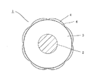
従来の永久磁石形モータは、図3に示すように、回転軸2の外周に嵌合した積層された回転子鉄心3の外周に複数個のセグメント形永久磁石4を接着剤6で固定して固定子1を構成していた。
ところが、永久磁石形モータの高速化に伴い、回転子の高速回転による遠心力の増加やそれに伴う温度上昇による接着剤の熱劣化により、回転子鉄心に固着した永久磁石が剥離し脱落する恐れがあった。これに対して、永久磁石の接着剥離を防止するために、永久磁石を筒状のカバー体にて覆ったり(例えば、特許文献1)、セグメント形永久磁石を樹脂材料で充填することで一体に成形する方法など、種々の工夫がなされている。
【0003】
【特許文献1】
特開平6−284650号公報
【0004】
【発明が解決しようとする課題】
しかしながら、このような従来技術においては、いずれも製造が面倒でコストが高いという問題があった。また、回転子鉄心にスリット状の溝を形成しその中にセグメント形永久磁石の端部をはめ込むことで遠心力方向の剥離を押さえる方法なども考えられるが、永久磁石の端部を回転子鉄心で覆うため磁束もれが大きくなってしまうなど問題があった。
本発明は、このような問題を解決するためになされたもので、積層された回転子鉄心の外周に接着剤で固着した永久磁石が高速回転でも剥離しにくく、かつ良好な磁気特性を有する構造をした回転子を備えた永久磁石形モータを安価に提供することを目的とするものである。
【0005】
【課題を解決するための手段】
上記問題を解決するため、本発明は、積層された回転子鉄心の外周に複数個のセグメント形永久磁石を接着剤を用いて等間隔に固着して回転子を構成している永久磁石形モータにおいて、前記回転子鉄心にピン状の爪を具備し、永久磁石接着後に爪を折り曲げて永久磁石を押さえるようにしたものである。
本発明によれば、高速回転永久磁石形モータにおいて永久磁石接着剥離を防止し、安定性や信頼性の高い永久磁石形モータを実現できる。また鉄は機械的応力を加えることで磁気特性が悪くなるので、折り曲げることで爪によるもれ磁束は低減される。さらに永久磁石を押さえつける爪が接着剤が固まるまでに永久磁石を保持する治具の役割も果たすため、永久磁石の接着作業を効率的に行うことができる。
【0006】
【発明の実施の形態】
以下、本発明の実施例を図に基づいて説明する。
[第1の実施例]
請求項1および請求項2の発明に関する実施例である。本実施例では8極の永久磁石形モータを例として説明する。
図1は、本発明の第1の実施例における永久磁石形モータの回転子を示す図で、(a)は正断面図で、(b)は(a)における矢印A方向からみた図である。回転子1は、回転軸2、回転子鉄心3、セグメント形永久磁石4により構成されている。回転子鉄心3の材質には、S60の珪素鋼板を用いている。この珪素鋼板を少なくとも1箇所ピン状の爪形の穴を有した円形の型で打抜き、爪5の間隔が永久磁石4と永久磁石4の隙間の間隔に合うように打抜いた鋼板を1枚毎に機械角で45°回転させて積層した。このようにすることにより、ひとつの型で8箇所からピン状の爪5が出た回転子鉄心3を形成することができる。
次に回転子鉄心3に回転軸2を圧入した後、回転子鉄心3の外周に加熱硬化型のエポキシ系接着剤6を塗布する。その後8個のネオジウム系の永久磁石4を爪5と爪5の間に等間隔に配置し、爪5を折り曲げて永久磁石4を両側から押さえつける。爪5が永久磁石4を保持する治具の役割も同時に果たしているため、このままの状態で炉に入れ、適切な温度で、適当な時間だけ加熱することで接着剤を硬化させる。
このようにして製作した回転子1を有する永久磁石形モータと、図3に示すような接着剤のみでセグメント形永久磁石4を固定している一般的な永久磁石形モータとで、永久磁石4が飛散するまで回転数を徐々に上げていく破壊試験を行った。その結果、一般的な永久磁石形モータの永久磁石が飛散した回転数Nに対して2倍の回転数2Nでも永久磁石の飛散は認められなかった。
本発明の永久磁石形モータは、接着剤に加えて1個ないし2個のピン状の爪5で永久磁石4の両側を押さえているため、より強固に永久磁石4の剥離を防止することができる。
またガウスメータを用いて、本発明の永久磁石形モータの各永久磁石4の最大磁束密度を測定した。その結果、最大磁束密度はMで、爪で押さえていない永久磁石の最大磁束密度Mと差がなく、磁束の漏れは認められなかった。しかし、永久磁石4を押さえつける爪5の数を片側5本に増やすと最大磁束密度は0.9Mと1割低下が認められた。よって永久磁石形モータが良好な磁気特性を有するためには、ピン状の爪5は1個ないし2個が望ましい。
[第2の実施例]
請求項3の発明に関する実施例である。本実施例では8極の永久磁石形モータを例として説明する。
図2は、本発明の第2の実施例における永久磁石形モータの回転子を示す図で、(a)は正断面図で、(b)は(a)における矢印B方向からみた図である。
回転子1は、回転軸2、回転子鉄心3、セグメント形永久磁石4により構成されている。回転子鉄心3の材質には、S60の珪素鋼板を用いている。この珪素鋼板を等間隔に8箇所ピン状の爪形の穴を有した円形の型で打抜き、爪のない円形の型で打抜いた鋼板を積層した回転子鉄心3の両外側に1枚ずつ爪5のある鋼板を積層する。このようにすることにより、両外側に8箇所からピン状の爪5が出た回転子鉄心3を形成することができる。
次に回転子鉄心3に回転軸2を圧入した後、回転子鉄心3の外周に加熱硬化型のエポキシ系接着剤6を塗布する。その後8個のネオジウム系の永久磁石4を、爪5が永久磁石4のほぼ中央に当たるように等間隔に配置し、爪5を折り曲げて永久磁石4を両側から押さえつける。爪5が永久磁石4を保持する治具の役割も同時に果たしているため、このままの状態で炉に入れ、適切な温度で、適当な時間だけ加熱することで接着剤を硬化させる。
このようにして製作した回転子1を有する永久磁石形モータと、図3に示すような接着剤のみでセグメント形永久磁石4を固定している一般的な永久磁石形モータとで、永久磁石が飛散するまで回転数を徐々に上げていく破壊試験を行った。その結果、一般的な永久磁石形モータの永久磁石が飛散した回転数Nに対して2倍の回転数2Nでも永久磁石の飛散は認められなかった。本発明の永久磁石形モータは、接着剤に加えてピン状の爪5で永久磁石4の両側を押さえているため、より強固に永久磁石の剥離を防止することができる。
またガウスメータを用いて本発明の永久磁石形モータの各永久磁石4の最大磁束密度を測定した。その結果、最大磁束密度はMで、爪で5押さえていない永久磁石4の最大磁束密度Mと差がなく、磁束の漏れは認められなかった。しかし、永久磁石4を押さえつける爪5の形状をピンではなく幅5mmの板状にすると磁束密度は0.9Mと一割低下が認められた。よって永久磁石形モータが良好な磁気特性を有するためには、幅の太くないピン状の爪が望ましい。
【0007】
【発明の効果】
以上述べたように、本発明によれば、次のような効果がある。
(1)積層された鉄心に具備されたピン状の爪でセグメント形永久磁石を押さえることで、接着剤と併用して永久磁石を固定させるので、高速回転永久磁石形モータにおいて永久磁石接着剥離を防止し、安定性や信頼性の高い永久磁石形モータを実現することができる。
(2)セグメント形永久磁石を押さえつける爪が接着剤が固まるまでに永久磁石を保持する治具の役割も果たすため、永久磁石の接着作業を効率的に行うことができる。
【図面の簡単な説明】
【図1】本発明の第1の実施例における永久磁石形モータの回転子を示す図で、(a)は正断面図で、(b)は(a)における矢印A方向からみた図である。
【図2】本発明の第2の実施例における永久磁石形モータの回転子を示す図で、(a)は正断面図で、(b)は(a)における矢印B方向からみた図である。
【図3】従来技術における永久磁石形モータの回転子を示す正断面図である。
【符号の説明】
1:回転子
2:回転軸
3:回転子鉄心
4:セグメント形永久磁石
5:ピン状の爪
6:接着剤[0001]
TECHNICAL FIELD OF THE INVENTION
The present invention relates to a permanent magnet type motor using segmented permanent magnets divided in a circumferential direction, and more particularly to a permanent magnet fixing structure for a rotor.
[0002]
[Prior art]
2. Description of the Related Art In recent years, high-speed rotation of a permanent magnet type motor has been desired in accordance with high functionality and high productivity of devices equipped with a permanent magnet type motor such as robots and machine tools.
In the conventional permanent magnet type motor, as shown in FIG. 3, a plurality of segment type
However, as the speed of the permanent magnet motor increases, the centrifugal force increases due to the high-speed rotation of the rotor, and the thermal deterioration of the adhesive due to the rise in temperature may cause the permanent magnet fixed to the rotor core to peel off and fall off. there were. On the other hand, in order to prevent adhesion and separation of the permanent magnet, the permanent magnet is covered with a cylindrical cover body (for example, Patent Document 1), or a segment-shaped permanent magnet is filled with a resin material to integrally form the permanent magnet. Various devices such as a molding method have been devised.
[0003]
[Patent Document 1]
JP-A-6-284650
[Problems to be solved by the invention]
However, such conventional techniques have a problem that manufacturing is troublesome and costly. It is also conceivable to form a slit-shaped groove in the rotor core and insert the end of the segment-shaped permanent magnet into the groove to suppress centrifugal separation.However, the end of the permanent magnet may be replaced with the rotor core. There is a problem that the magnetic flux leakage becomes large because of the covering.
The present invention has been made in order to solve such a problem, and a structure in which a permanent magnet fixed to an outer periphery of a laminated rotor core with an adhesive is not easily separated even at high speed rotation and has good magnetic properties. It is an object of the present invention to provide an inexpensive permanent magnet type motor having a rotor having the above configuration.
[0005]
[Means for Solving the Problems]
In order to solve the above problem, the present invention provides a permanent magnet type motor in which a plurality of segment type permanent magnets are fixed at equal intervals to the outer periphery of a laminated rotor core using an adhesive to form a rotor. , A pin-shaped claw is provided on the rotor core, and after the permanent magnet is bonded, the claw is bent to hold down the permanent magnet.
ADVANTAGE OF THE INVENTION According to this invention, permanent magnet adhesion peeling is prevented in a high-speed rotation permanent magnet type motor, and a highly stable and reliable permanent magnet type motor can be realized. In addition, since magnetic properties of iron deteriorate due to the application of mechanical stress, the magnetic flux leaking from the nail is reduced by bending the iron. Further, the nail for holding down the permanent magnet also functions as a jig for holding the permanent magnet until the adhesive hardens, so that the work of bonding the permanent magnet can be performed efficiently.
[0006]
BEST MODE FOR CARRYING OUT THE INVENTION
Hereinafter, embodiments of the present invention will be described with reference to the drawings.
[First Embodiment]
This is an embodiment relating to the first and second aspects of the present invention. In this embodiment, an 8-pole permanent magnet type motor will be described as an example.
FIGS. 1A and 1B are views showing a rotor of a permanent magnet type motor according to a first embodiment of the present invention, wherein FIG. 1A is a front sectional view, and FIG. 1B is a view seen from the direction of arrow A in FIG. . The
Next, after the rotating
The permanent magnet type motor having the
In the permanent magnet type motor of the present invention, since one or two pin-
The maximum magnetic flux density of each
[Second embodiment]
This is an embodiment according to the third aspect of the present invention. In this embodiment, an 8-pole permanent magnet type motor will be described as an example.
2A and 2B are diagrams showing a rotor of a permanent magnet type motor according to a second embodiment of the present invention, wherein FIG. 2A is a front sectional view, and FIG. 2B is a diagram viewed from the direction of arrow B in FIG. .
The
Next, after the
The permanent magnet type motor having the
The maximum magnetic flux density of each
[0007]
【The invention's effect】
As described above, the present invention has the following effects.
(1) Since the permanent magnets are fixed together with the adhesive by pressing the segment-shaped permanent magnets with pin-shaped claws provided on the laminated iron core, the permanent magnets are peeled off in a high-speed rotating permanent magnet type motor. Thus, a permanent magnet type motor having high stability and high reliability can be realized.
(2) Since the claws that press the segment-shaped permanent magnets also serve as jigs for holding the permanent magnets until the adhesive hardens, the permanent magnets can be bonded efficiently.
[Brief description of the drawings]
FIGS. 1A and 1B are diagrams showing a rotor of a permanent magnet type motor according to a first embodiment of the present invention, wherein FIG. 1A is a front sectional view and FIG. 1B is a diagram viewed from the direction of arrow A in FIG. .
FIGS. 2A and 2B are views showing a rotor of a permanent magnet type motor according to a second embodiment of the present invention, wherein FIG. 2A is a front sectional view and FIG. 2B is a view as seen from the direction of arrow B in FIG. .
FIG. 3 is a front sectional view showing a rotor of a permanent magnet type motor according to the related art.
[Explanation of symbols]
1: rotor 2: rotating shaft 3: rotor core 4: segment-shaped permanent magnet 5: pin-shaped claw 6: adhesive
Claims (3)
前記回転子鉄心にピン状の爪を具備し、永久磁石接着後に爪を折り曲げて永久磁石を押さえることを特徴とする永久磁石形モータ。In a permanent magnet type motor in which a rotor is formed by fixing a plurality of segment type permanent magnets on an outer periphery of a laminated rotor core at equal intervals using an adhesive,
A permanent magnet type motor comprising: a rotor core having pin-shaped claws; and bending the claws to hold down the permanent magnets after bonding the permanent magnets.
Priority Applications (1)
| Application Number | Priority Date | Filing Date | Title |
|---|---|---|---|
| JP2003018118A JP2004236366A (en) | 2003-01-28 | 2003-01-28 | Permanent magnet type motor |
Applications Claiming Priority (1)
| Application Number | Priority Date | Filing Date | Title |
|---|---|---|---|
| JP2003018118A JP2004236366A (en) | 2003-01-28 | 2003-01-28 | Permanent magnet type motor |
Publications (1)
| Publication Number | Publication Date |
|---|---|
| JP2004236366A true JP2004236366A (en) | 2004-08-19 |
Family
ID=32948332
Family Applications (1)
| Application Number | Title | Priority Date | Filing Date |
|---|---|---|---|
| JP2003018118A Pending JP2004236366A (en) | 2003-01-28 | 2003-01-28 | Permanent magnet type motor |
Country Status (1)
| Country | Link |
|---|---|
| JP (1) | JP2004236366A (en) |
Cited By (6)
| Publication number | Priority date | Publication date | Assignee | Title |
|---|---|---|---|---|
| JP2007104820A (en) * | 2005-10-05 | 2007-04-19 | Nissan Motor Co Ltd | Rotating electric machine |
| JP2008109726A (en) * | 2006-10-23 | 2008-05-08 | Mitsubishi Electric Corp | Rotating machine rotor |
| JP2008141799A (en) * | 2006-11-30 | 2008-06-19 | Mitsubishi Electric Corp | Rotating machine rotor |
| JP2011135735A (en) * | 2009-12-25 | 2011-07-07 | Nsk Ltd | Rotor for brushless motor, brushless motor, electric power steering device, and method of manufacturing rotor for brushless motor |
| WO2011125183A1 (en) * | 2010-04-07 | 2011-10-13 | トヨタ自動車株式会社 | Rotor and manufacturing method for same |
| US10665387B2 (en) | 2016-05-10 | 2020-05-26 | GM Global Technology Operations LLC | Method of fabrication of a curvilinear magnet |
Citations (5)
| Publication number | Priority date | Publication date | Assignee | Title |
|---|---|---|---|---|
| JPH06133513A (en) * | 1992-08-26 | 1994-05-13 | Matsushita Refrig Co Ltd | Rotor of self-starting permanent magnet synchronous motor |
| JPH06284650A (en) * | 1993-03-29 | 1994-10-07 | Sanden Corp | Assembling method for permanent magnet type rotor |
| JPH10191586A (en) * | 1996-12-26 | 1998-07-21 | Japan Servo Co Ltd | Rotor of motor having magnet |
| JP2001037122A (en) * | 1999-07-23 | 2001-02-09 | Sankyo Seiki Mfg Co Ltd | Rotor for motor |
| WO2001063726A2 (en) * | 2000-02-26 | 2001-08-30 | Robert Bosch Gmbh | Magnet retainer and method for fixing a magnet on a support element |
-
2003
- 2003-01-28 JP JP2003018118A patent/JP2004236366A/en active Pending
Patent Citations (5)
| Publication number | Priority date | Publication date | Assignee | Title |
|---|---|---|---|---|
| JPH06133513A (en) * | 1992-08-26 | 1994-05-13 | Matsushita Refrig Co Ltd | Rotor of self-starting permanent magnet synchronous motor |
| JPH06284650A (en) * | 1993-03-29 | 1994-10-07 | Sanden Corp | Assembling method for permanent magnet type rotor |
| JPH10191586A (en) * | 1996-12-26 | 1998-07-21 | Japan Servo Co Ltd | Rotor of motor having magnet |
| JP2001037122A (en) * | 1999-07-23 | 2001-02-09 | Sankyo Seiki Mfg Co Ltd | Rotor for motor |
| WO2001063726A2 (en) * | 2000-02-26 | 2001-08-30 | Robert Bosch Gmbh | Magnet retainer and method for fixing a magnet on a support element |
Cited By (6)
| Publication number | Priority date | Publication date | Assignee | Title |
|---|---|---|---|---|
| JP2007104820A (en) * | 2005-10-05 | 2007-04-19 | Nissan Motor Co Ltd | Rotating electric machine |
| JP2008109726A (en) * | 2006-10-23 | 2008-05-08 | Mitsubishi Electric Corp | Rotating machine rotor |
| JP2008141799A (en) * | 2006-11-30 | 2008-06-19 | Mitsubishi Electric Corp | Rotating machine rotor |
| JP2011135735A (en) * | 2009-12-25 | 2011-07-07 | Nsk Ltd | Rotor for brushless motor, brushless motor, electric power steering device, and method of manufacturing rotor for brushless motor |
| WO2011125183A1 (en) * | 2010-04-07 | 2011-10-13 | トヨタ自動車株式会社 | Rotor and manufacturing method for same |
| US10665387B2 (en) | 2016-05-10 | 2020-05-26 | GM Global Technology Operations LLC | Method of fabrication of a curvilinear magnet |
Similar Documents
| Publication | Publication Date | Title |
|---|---|---|
| CN113169595B (en) | Laminated iron core, iron core block, rotating electrical machine and method for manufacturing iron core block | |
| CN113196618B (en) | Laminated iron core and rotating motor | |
| JP7055209B2 (en) | Laminated core and rotary electric machine | |
| JP6095827B1 (en) | Manufacturing method of rotor for rotating electrical machine | |
| US8080907B2 (en) | Rotor of brushless (BL) motor | |
| JP3482365B2 (en) | Embedded magnet rotor | |
| JP5292271B2 (en) | Permanent magnet rotating electric machine | |
| JP2004153913A (en) | Rotor for permanent magnet motor | |
| JPWO2020129924A1 (en) | Laminated core and rotary electric machine | |
| WO2020129937A1 (en) | Laminated core and rotating electric machine | |
| CN103259357B (en) | By means of the fixation to permanent magnet of framework | |
| US10291092B2 (en) | Rotor and motor including the same | |
| JPH09163649A (en) | Fixing method of permanent magnet in permanent magnet embedded motor | |
| JP2001258187A (en) | Permanent magnet embedded rotor of permanent magnet motor | |
| JP6135770B2 (en) | Permanent magnet embedded rotary electric machine and method for manufacturing the same | |
| JP2011109774A (en) | Rotating electric machine | |
| JP4397466B2 (en) | Permanent magnet rotating electric machine | |
| JP2012213268A (en) | Rotary electric machine | |
| CN105305681A (en) | Rotor package of rotating motor | |
| JP4930127B2 (en) | Surface magnet type rotor and manufacturing method thereof | |
| KR100503721B1 (en) | Direct current motor | |
| JP2016042771A (en) | Rotor and electric motor equipped with the rotor | |
| JP2000152535A (en) | Permanent magnet motor rotor | |
| CN101375486B (en) | Motor | |
| JPS61106049A (en) | Permanent magnet rotor of rotating electric machine |
Legal Events
| Date | Code | Title | Description |
|---|---|---|---|
| A621 | Written request for application examination |
Free format text: JAPANESE INTERMEDIATE CODE: A621 Effective date: 20050830 |
|
| A977 | Report on retrieval |
Free format text: JAPANESE INTERMEDIATE CODE: A971007 Effective date: 20071220 |
|
| A131 | Notification of reasons for refusal |
Free format text: JAPANESE INTERMEDIATE CODE: A131 Effective date: 20071225 |
|
| A521 | Written amendment |
Free format text: JAPANESE INTERMEDIATE CODE: A523 Effective date: 20080222 |
|
| A131 | Notification of reasons for refusal |
Free format text: JAPANESE INTERMEDIATE CODE: A131 Effective date: 20090413 |
|
| A02 | Decision of refusal |
Free format text: JAPANESE INTERMEDIATE CODE: A02 Effective date: 20090805 |