【0001】
【発明の属する技術分野】
本発明は、排出オ−ガの操作装置に関し、グレンタンクから穀粒を機外に排出する排出オ−ガにおいて、伸縮作動と、上下方向の高さ調節作動と、旋回作動との各操作を、コンバインの操作装置と、該コンバインから離れた位置のリモコン操作装置との両方から操作を可能とした技術で農業機械の技術分野に属するものである。
【0002】
【従来の技術】
従来からコンバインは、刈取穀稈を脱穀する脱穀装置と、脱穀後の穀粒を収納貯溜するためのグレンタンクとを併設して刈取脱穀作業を連続的に行うことができる構成としている。そして、グレンタンクは、作業の進行にともなって順次貯溜される穀粒が満杯に達すると、内装している排出螺旋から、揚穀装置、穀粒排出オ−ガを利用して、貯溜穀粒を待機中のトラックのタンクに搬出する構成としている。
【0003】
そして、具体的な公知文献(例えば、特許文献1参照)は、グレンタンクにアンロ−ダを装備したコンバインにおいて、アンロ−ダの操作を遠隔操作により行なうようにし、又、アンロ−ダによる穀物の体積状態をモニタにより観察できるようにしたコンバイン用穀物ハンドリング装置が提示されている。
【0004】
【特許文献1】
特開平6−90611号公報(第2、乃至4頁、第1、乃至4図)
【0005】
【発明が解決しようとする課題】
上述した従来型のアンロ−ダを遠隔操作する装置は、アンロ−ダの左右旋回、上下移動、又は穀物排出クラッチ装置の入、切り操作を可能としている。そして、コンバインの運転席では、モニタを見ながら上記操作ができる構成になっている。
【0006】
しかしながら、該従来型のモニタ付遠隔操作装置は、排出オ−ガが伸縮作動するズ−ムオ−ガの操作が、上記した各作動操作と同等に行なうことができる構成になっていない課題がある。
更に、上述した従来型のアンロ−ダを遠隔操作する装置は、運搬車の荷台の近くでオペレ−タAが行なう操作装置と、コンバインの運転席に座ってモニタを見ながら操作するオペレ−タBの操作との関連性については全く配慮がされていない構成である。したがって、この従来装置は、常に、いずれか一方側でのみ操作することを前提にした装置であって、実作業ではきわめて不便であり、同時に操作をすると、オペレ−タAとBと行なう操作指令が競合した場合、安全性に欠ける課題がある。
【0007】
【課題を解決するための手段】
本発明は、上述した課題を解決するために、次の如き技術手段を講ずるものである。まず、請求項1の発明は、コンバイン1のグレンタンク2に貯留した穀粒を機外に排出する排出オ−ガ3を設け、該排出オ−ガ3は、移動筒4の先端部に開口した穀粒排出口5が筒方向に伸縮自由であって、上下方向にも高さの調節を可能とし、更に、前記コンバインの上方を旋回作動できる構成とし、前記伸縮作動と、上下方向の高さ調節作動と、旋回作動とをコンバイン1に装置した操作装置6と、該コンバイン1の機体から離れた位置で操作を可能としたリモコン操作装置7との両方から操作を可能にしたことを特徴とする排出オ−ガの操作装置であって、排出オ−ガの穀粒排出口の伸縮作動と、上下方向の調節作動と、旋回作動とが、コンバインの操縦座席と、コンバインの機体から離れた位置との両方から自由に操作することができる。
【0008】
つぎに、請求項2の発明は、排出オ−ガ3は、伸縮作動か、又は上下方向の高さ調節作動か、或いは旋回作動のいずれかの操作を、コンバイン1の操作装置6と、該コンバイン1から離れた位置のリモコン操作装置7との両方から同時に操作をする場合において、両方が異なった作動を操作指令したときには、前記排出オ−ガ3は、移動停止の状態になることを特徴とする請求項1記載の排出オ−ガの操作装置であって、機体側とリモコン側との操作が異なった場合の安全性を確保できる構成となっている。
【0009】
つぎに、請求項3の発明は、排出オ−ガ3は、コンバイン1上に設けた収納受具8に収納状態にある時には、リモコン操作装置7を操作しても作動せず、そのまま収納状態を保つことを特徴とする請求項1記載の排出オ−ガの操作装置であって、リモコン操作装置は、コンバインが刈取脱穀作業をしているとき(排出オ−ガ3は収納位置にある。)には、補助作業者が持ち運ぶことが多く、通常、作業着のポケットに入れて歩いている。したがって、リモコン操作装置は、補助作業者の意に反して何かに圧ぱくされてスイッチが押されて操作指令を発することがあり、より高い安全を確保することができる構成としている。
【0010】
【発明の効果】
本発明は、以上のように構成したから、請求項1の発明は、ズ−ムオ−ガにおける穀粒排出口の伸縮作動と、上下方向の調節作動と、旋回作動とを、コンバインの操縦座席と、コンバインの機体から離れた位置との両方から自由に操作指令を発して作動させることができる特徴がある。
【0011】
そして、請求項2の発明は、機体側の操作装置と、リモコン側の操作装置との両方から同時に異なった操作指令が発せられた場合、排出オ−ガが作動停止の状態になって、安全性を確保できる特徴がある。
そして、請求項3の発明は、コンバインを走行して刈取脱穀作業をしているときには、ほとんどの場合、排出オ−ガは収納位置にある。そのようなコンバイン作業中に、リモコン操作装置は、補助作業者が持ち運ぶことが多く、通常、作業着のポケットに入れて歩いている。したがって、リモコン操作装置は、補助作業者の意に反して何かに圧ぱくされてスイッチが押されて操作指令を発することがあり、本案発明は、より高い安全を確保することができる優れた効果がある。
【0012】
【発明の実施の形態】
以下、本発明の実施の形態を説明する。
まず、コンバイン1は、図1、及び図2に示すように、左右一対のクロ−ラ10、10を設けた車体11上に、脱穀装置12を搭載し、その前側に刈取前処理装置13を設けて刈取脱穀作業ができる構成としている。
【0013】
そして、グレンタンク2は、図面に示すように、上記脱穀装置12の側部に併設して前述した車体11上に搭載し、その脱穀装置12から一番揚穀装置14を介して揚穀されてきた脱穀・選別後の穀粒を貯溜できる構成としている。そして、グレンタンク2は、図3に示すように、底部に軸装した排出螺旋15の始端側を機外の伝動軸にクラッチ装置16を介して連結し、その螺旋の終端側を揚穀筒17の下部まで延長して、内装している揚穀螺旋18の下端部に接続して構成している。
【0014】
そして、排出オ−ガ3は、図1、乃至図3に示すように、上記揚穀筒17の上部に上下方向へ回動自由に接続する固定搬送筒19と、これに接続する伸縮可能な移動筒4とからズ−ムオ−ガを構成している。実施例の場合、固定搬送筒19は、図面に示すように、基部を前記揚穀筒17の上部に連結し、先端部を外方に延長して設け、その筒内には、始端部を前記揚穀螺旋18に接続した搬送螺旋20を内装して、揚穀筒17から受け継いだ穀粒を搬送する構成としている。
【0015】
そして、移動筒4は、先端部に穀粒排出口5を開口して設け、基部側を、前記固定搬送筒19の先端側から摺動自由に挿入嵌合して伸縮可能に連結して構成している。そして、前記移動筒4は、内部に伸縮螺旋21を内装しており、固定搬送筒19に対して伸縮移動するとき、追従して伸縮し、尚且つ、搬送が可能な構成としている。
【0016】
そして、旋回装置22は、図3に示すように、旋回制御モ−タ23の出力軸24に軸着した旋回駆動ギヤ25に揚穀筒17の外周に固定した旋回ギヤ26を噛合して構成している。この場合、揚穀筒17は、排出オ−ガ3と一体となって、オ−ガ旋回スイッチ27a、27bによって正逆回転し、左旋回、又は右旋回ができる構成としている。なお、39はオ−ガ旋回位置センサを示す。
【0017】
そして、上下調節装置28は、揚穀筒17の上部と排出オ−ガ3の基部との連結部分の内側において、一方を揚穀筒17側に、他方を排出オ−ガ3側にそれぞれ取り付けた油圧制御シリンダ29から構成している。この場合、油圧制御シリンダ29は、上下スイッチ30a、30bの操作に基づいて、ソレノイドバルブ31を切替えて作動油を送って伸縮し、排出オ−ガ3(穀粒排出口5)の上下高さ調節ができる構成としている。
【0018】
つぎに、伸縮駆動装置32は、図3に示すように、揚穀筒17の上部に近い固定搬送筒19の基部上に装備した伸縮制御モ−タ33に減速装置を介して螺旋軸34の基端部を連結して強制駆動する構成としている。そして、移動装置35は、上記螺旋軸34の螺旋溝に係合して強制的に軸方向に移動するように設け、前記移動筒4の基部側に一体的に連結して構成している。
【0019】
そして、伸縮駆動装置32は、図3に示すように、縮小側と伸長側とにそれぞれリミットセンサS1、S2を設けて前記移動装置35が到達して接触すると、前記伸縮制御モ−タ33を自動停止する構成としている。
そして、伸縮制御モ−タ33は、伸長スイッチ36aと縮小スイッチ36bのON操作に基づいて駆動され、螺旋軸34を正転、又は逆転方向に回転する構成としている。そして、移動筒4は、螺旋軸34が正転すれば係合している移動装置35を介して伸長し、逆転すれば縮小方向に強制的に移動する構成としている。
【0020】
このようにして、移動筒4は、固定搬送筒19に嵌合した状態で筒に沿って伸び縮みして、先端部の穀粒排出口5の位置を、基部の揚穀筒17に対して、遠ざけたり、近ずけたり調節して穀粒の落下位置を選択できる構成としている。そして、排出オ−ガ3は、図1に示すように、機体への収納時には脱穀装置12上の収納受具8に受け止められて収納される構成としている。そして、収納受具8は、収納時の排出オ−ガ3を検出する収納センサ37を設けている。
【0021】
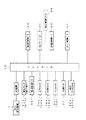
以上のように構成された実施例の各作動を制御するコントロ−ラ38を、上記した説明と重複する部分が多いが、図4、及び図5にまとめて再度説明する。
まず、コントロ−ラ38は、図4、及び図5に示すように、制御プログラムや基準デ−タ等を内蔵したメモリを有するマイクロコンピュ−タの演算制御部であって、算術、論理および比較演算等を行なう構成となっている。そして、コントロ−ラ38は、入力側に、リモコン操作装置7の送信機からコンバイン1の受信機を経由した入力部が接続されており、それに加えて、前述の旋回スイッチ(左旋回、右旋回)27a、27bと、オ−ガの旋回位置センサ39と、上下スイッチ30a、30bと、伸縮スイッチ(伸長スイッチ、縮小スイッチ)36a、36bと、伸縮リミットセンサS1、S2と、収納センサ37と、排出クラッチ入、切スイッチ42a、42bを接続して構成している。
【0022】
そして、コントロ−ラ38は、出力側に旋回制御モ−タ23と、ソレノイドバルブ31(油圧制御シリンダ29)と、伸縮制御モ−タ33と、クラッチ制御モ−タ51を接続して構成している。
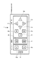
以上のように構成した各操作スイッチ、すなわち、旋回スイッチ27a、27b、上下スイッチ30a、30b、伸縮スイッチ36a、36bは、コンバイン1の操縦座席50の側部に配置した操作装置6と、該コンバイン1の機体から離れた位置で、無線によって操作を可能としたリモコン操作装置7(図6参照)とに配置して設け、両方から操作を可能に構成している。そして、リモコン操作装置7は、図6に示すように、自動張り出しスイッチ40と自動収納スイッチ41、排出クラッチ入、切スイッチ42a、42bを設けてコントロ−ラ38に無線で接続する構成としている。
【0023】
そして、操作装置6とリモコン操作装置7とは、実作業や排出オ−ガ3の安全性を確保するために、以下に説明するそれぞれの実施例のような関係を保つ安全な制御ができる構成としている。
まず、上記構成において、排出オ−ガ3は、収納受具8に収納状態にある時には、リモコン操作装置7の各スイッチを操作しても収納状態を保ち、遠隔操作ができない構成にしている。
【0024】
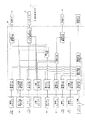
そして、コントロ−ラ38は、コンバイン1側の操作装置6からのスイッチ操作と、リモコン操作装置7からのスイッチ操作とが異なった操作指令であるときには、図7のフロ−で示すように、旋回、上下、伸縮の作動中であっても、その作動を停止して、排出クラッチも切り、伝動も中断する制御を行なう構成としている。
【0025】
そのために、操作装置6とリモコン操作装置7は、リセットスイッチ45を設けてやり直しができる構成としている。図7に示すフロ−の手順は、操作装置6とリモコン操作装置7との両方側のスイッチ操作が重複した場合を示している。
このように構成することによって、排出オ−ガ3は、作動の安全が保持され、安心して操作ができる特徴がある。
【0026】
そして、コントロ−ラ38は、コンバイン1が所定の速度で走行しているときには、リモコン操作装置7によってスイッチ操作をしても、排出オ−ガ3が作動せず、停止状態を保ち、安全性を確保できる構成としている。
なお、操作装置6とリモコン操作装置7には、それぞれ作動停止スイッチ46を設けて、どちらからでも作動中の排出オ−ガ3を停止できる構成として安全性を確保するものとなっている。
【0027】
そして、別実施例の場合、コントロ−ラ38は、コンバイン1の機体側にある操作装置6をリモコン操作装置7より優先した構成にしている。
そして、他の実施例では、操作装置6とリモコン操作装置7とは、それぞれトランシ−バ装置をセットして、会話による交信を可能に構成する。通常の作業中には、エンジン音、作業騒音が大きくコンバイン1上の作業者と、地上の補助作業者との連絡がとり難いため、トランシ−バを利用して会話による交信を可能にし、安全性を更に高めることができるものとしている。
【0028】
そして、リモコンによる排出オ−ガ3の操作をより安全にするために、リモコン操作装置7を、使用可の状態と使用不可の状態とに切替ができる構成にするとよい。この場合、切替スイッチは、コンバイン1側か、又はリモコン操作装置7側かのいずれか一方に設けるか、或いは、両方に設けておくと便利である。
【0029】
一般に、リモコン操作は、機体側と遠隔操作との両方から操作ができる便利さがあって重宝するが、反面、誤操作の危険性も含んでおり、より安全な作業を行なうためと、併せて操作性を向上するために、切替装置を設ける意義がある。
以上、本発明について、各実施例を説明したが、請求項1の発明は、ズ−ムオ−ガにおける穀粒排出口5の伸縮作動と、上下方向の調節作動と、旋回作動とを、コンバイン1の操縦座席50と、コンバイン1の機体から離れた位置との両方から自由にスイッチ操作をして作動させることができるものである。
【0030】
そして、請求項2の発明は、両方からの操作指令が競合した場合の安全を確保する手段であって、機体側の操作装置6と、リモコン側の操作装置7との両方から同時に異なった操作指令が発せられた場合、排出オ−ガ3の作動を停止して安全性を確保できるものである。この場合、排出オ−ガ3は、排出クラッチを自動的に切りにすれば、更に安全性を高くすることができる。
【0031】
そして、請求項3の発明は、コンバイン1が圃場の中を走行して刈取脱穀作業をしているとき、又は路上走行をしているときには、リモコン操作装置7は、補助作業者が持ち運ぶことが多く、通常、作業着のポケットに入れて歩いている。したがって、リモコン操作装置7は、補助作業者の意に反して何かに圧ぱくされてスイッチが押されて操作指令を発することがあり、本案発明は、より高い安全を確保することができる優れたものである。
【図面の簡単な説明】
【図1】本発明の実施例であって、コンバインの正面図である。
【図2】本発明の実施例であって、コンバインの側面図である。
【図3】本発明の実施例であって、一部を破断して示す側面図である。
【図4】本発明の実施例であって、制御機構のブロック図である。
【図5】本発明の実施例であって、制御機構のブロック図である。
【図6】本発明の実施例であって、リモコン操作装置の正面図である。
【図7】本発明の実施例であって、操作例のフロ−を示すブロック図である。
【符号の説明】
1 コンバイン 2 グレンタンク
3 排出オ−ガ 4 移動筒
5 穀粒排出口 6 操作装置
7 リモコン操作装置 8 収納受具。[0001]
TECHNICAL FIELD OF THE INVENTION
The present invention relates to a discharge auger operating device, and in a discharge auger that discharges grains from a Glen tank to the outside of a machine, performs operations of a telescopic operation, a vertical height adjustment operation, and a turning operation. , Which belongs to the technical field of agricultural machinery by a technique enabling operation from both a combine operating device and a remote control operating device at a position remote from the combine.
[0002]
[Prior art]
Conventionally, the combine has a configuration in which a threshing device for threshing a harvested grain culm and a Glen tank for storing and storing the grain after threshing are provided in parallel so that the harvesting and threshing operation can be continuously performed. Then, when the grains sequentially stored in the Glen tank are filled with the progress of the work, the stored grains are discharged from the built-in discharge spiral by using a grain raising device and a grain discharge auger. Is carried out to a tank of a waiting truck.
[0003]
A specific known document (for example, refer to Patent Document 1) discloses that a combine tank equipped with an unloader is used to remotely control the unloader and to control the grain by the unloader. There has been proposed a grain handling device for combine which allows the volume state to be observed by a monitor.
[0004]
[Patent Document 1]
JP-A-6-90611 (pages 2 to 4, pages 1 to 4)
[0005]
[Problems to be solved by the invention]
The above-mentioned conventional device for remotely controlling the unloader enables the unloader to turn left and right, move up and down, or operate the grain discharge clutch device to enter and disengage. In the driver's seat of the combine, the above operation can be performed while looking at the monitor.
[0006]
However, the conventional remote control device with a monitor has a problem that the operation of the zoom auger in which the discharge auger extends and retracts is not performed in the same manner as the above-described respective operation operations. .
Further, the above-mentioned conventional device for remotely controlling an unloader is composed of an operating device operated by an operator A near a carrier of a carrier, and an operator operating a vehicle while sitting in a driver's seat of a combine and watching a monitor. In this configuration, no consideration is given to the relationship with the operation B. Therefore, this conventional device is a device on the premise that it is always operated on only one side, and it is extremely inconvenient in actual work. If it is operated at the same time, an operation command issued to the operators A and B is issued. In the case of conflict, there is a problem that lacks security.
[0007]
[Means for Solving the Problems]
The present invention takes the following technical means in order to solve the above-mentioned problems. First, the invention according to claim 1 is provided with a discharge auger 3 for discharging the grains stored in the Glen tank 2 of the combine 1 to the outside of the machine. The grain discharge port 5 is configured to be freely expandable and contractible in the cylinder direction, to be able to adjust the height also in the vertical direction, and to be capable of pivoting above the combine, so that the expansion and contraction operation and the vertical height It is characterized in that the operation can be performed from both the operating device 6 in which the adjusting operation and the turning operation are provided in the combine 1 and the remote control operating device 7 which can be operated in a position away from the fuselage of the combine 1. The operating device of the discharge auger, wherein the expansion / contraction operation of the grain discharge port of the discharge auger, the adjustment operation in the vertical direction, and the turning operation are separated from the control seat of the combine and the body of the combine. Can be operated freely from both the That.
[0008]
Next, the invention according to claim 2 is characterized in that the discharge auger 3 controls the operation device 6 of the combine 1 by performing any one of expansion and contraction operation, vertical height adjustment operation, and turning operation. When simultaneously operating from both the remote control operating device 7 located away from the combine 1 and both of them operate differently, the discharge auger 3 is in a state of stopping movement. The operation device of the discharge auger according to claim 1, wherein the operation can be ensured when the operation on the machine side and the operation on the remote controller side are different.
[0009]
Next, according to a third aspect of the present invention, when the discharge auger 3 is in a storage state in the storage receiver 8 provided on the combine 1, even if the remote control operating device 7 is operated, the discharge auger 3 is not operated. 2. The operating device for a discharge auger according to claim 1, wherein the remote aggregator is operated when the combine is performing harvesting and threshing work (the discharge auger 3 is at the storage position. ) Is often carried by an auxiliary worker, usually walking in a work clothes pocket. Therefore, the remote control operation device is configured to be able to issue an operation command by being pressed by something against the will of the auxiliary worker and being pressed, thereby ensuring higher safety.
[0010]
【The invention's effect】
Since the present invention is constructed as described above, the invention of claim 1 is characterized in that the expansion / contraction operation of the grain discharge port, the adjustment operation in the vertical direction, and the turning operation in the zoom ogre are performed by the control seat of the combine. In addition, there is a feature that the operation can be freely performed by issuing an operation command from both the position of the combine and the position away from the body of the combine.
[0011]
According to the second aspect of the present invention, when different operation commands are issued simultaneously from both the operating device on the machine side and the operating device on the remote controller, the discharge auger is stopped and the safety is stopped. There is a feature that can ensure the nature.
According to the third aspect of the present invention, when the harvesting and threshing operation is performed while traveling on the combine, the discharge auger is in the storage position in most cases. During such combine work, the remote control device is often carried by an auxiliary worker, and is usually walked in a work clothes pocket. Therefore, the remote control operation device may be pressed against something against the will of the auxiliary worker and the switch may be pressed to issue an operation command, and the present invention is an excellent remote control device that can ensure higher safety. effective.
[0012]
BEST MODE FOR CARRYING OUT THE INVENTION
Hereinafter, embodiments of the present invention will be described.
First, as shown in FIG. 1 and FIG. 2, the combine 1 mounts a threshing device 12 on a vehicle body 11 provided with a pair of left and right crawlers 10 and 10, and mounts a pre-cutting device 13 on a front side thereof. It is configured so that harvesting and threshing work can be performed.
[0013]
Then, as shown in the drawing, the Glen tank 2 is mounted on the above-described vehicle body 11 along with the side of the threshing device 12, and is grain-pulverized from the threshing device 12 via the first-throwing device 14. It is configured to store the grains after threshing and sorting. As shown in FIG. 3, the Glen tank 2 has a start end of a discharge spiral 15 mounted on the bottom connected to a transmission shaft outside the machine via a clutch device 16, and an end of the spiral is a hoisting cylinder. It extends to the lower part of 17 and is connected to the lower end of the fried spiral 18 inside.
[0014]
As shown in FIGS. 1 to 3, the discharge auger 3 is fixedly connected to the upper part of the above-mentioned frying cylinder 17 so as to be freely rotatable in the vertical direction, and is extendable and contractable. The moving cylinder 4 forms a zoom auger. In the case of the embodiment, as shown in the drawing, the fixed transporting cylinder 19 has a base connected to the upper part of the frying cylinder 17 and a front end extended outwardly. A transport spiral 20 connected to the above-mentioned helix spiral 18 is provided to transport the kernels inherited from the fry cylinder 17.
[0015]
The moving cylinder 4 is configured such that the grain discharge port 5 is provided at the distal end thereof with an opening, and the base side is slidably inserted from the distal end side of the fixed transport cylinder 19 to be fitted and slidably connected. are doing. The movable cylinder 4 has a telescopic spiral 21 inside, and is configured to be able to expand and contract following the expansion and contraction movement with respect to the fixed transport cylinder 19 and to be capable of being transported.
[0016]
As shown in FIG. 3, the swivel device 22 is configured by meshing a swivel gear 26 fixed to the outer periphery of the hoisting cylinder 17 with a swivel drive gear 25 mounted on an output shaft 24 of a swivel control motor 23. are doing. In this case, the fryer cylinder 17 is configured to be able to rotate left and right or right by turning integrally with the discharge auger 3 by the auger turning switches 27a and 27b. Reference numeral 39 denotes an auger turning position sensor.
[0017]
The vertical adjustment device 28 is mounted on the side of the fryer cylinder 17 and the other on the side of the discharge auger 3 inside the connection between the upper part of the fryer cylinder 17 and the base of the discharge auger 3, respectively. And a hydraulic control cylinder 29. In this case, based on the operation of the up / down switches 30a and 30b, the hydraulic control cylinder 29 switches the solenoid valve 31 to send and receive hydraulic oil and expands / contracts, and the vertical height of the discharge auger 3 (the grain discharge port 5). Adjustable configuration.
[0018]
Next, as shown in FIG. 3, the telescopic drive device 32 is connected to a telescopic control motor 33 mounted on the base of the fixed transport cylinder 19 near the upper part of the fryer cylinder 17 via a speed reducer. The structure is such that the base ends are connected to each other and are forcibly driven. The moving device 35 is provided so as to engage with the helical groove of the helical shaft 34 and move forcibly in the axial direction, and is integrally connected to the base side of the moving cylinder 4.
[0019]
As shown in FIG. 3, the expansion / contraction drive device 32 is provided with limit sensors S 1 and S 2 on the reduction side and the expansion side, respectively. 33 is automatically stopped.
The expansion / contraction control motor 33 is driven based on the ON operation of the expansion switch 36a and the reduction switch 36b, and rotates the helical shaft 34 in the forward or reverse direction. The moving cylinder 4 is configured to extend through the moving device 35 engaged when the helical shaft 34 rotates forward, and to move in the contracting direction when the helical shaft 34 rotates reversely.
[0020]
In this way, the movable cylinder 4 expands and contracts along the cylinder while being fitted to the fixed transport cylinder 19, and moves the position of the grain discharge port 5 at the distal end with respect to the milling cylinder 17 at the base. It is configured so that the drop position of the grain can be selected by adjusting the distance or approach distance. As shown in FIG. 1, the discharge auger 3 is configured to be received and stored in a storage receiver 8 on the threshing device 12 when stored in the machine body. The storage receiver 8 is provided with a storage sensor 37 for detecting the discharge auger 3 during storage.
[0021]
The controller 38 for controlling each operation of the embodiment configured as described above has many parts overlapping with the above description, but will be described again with reference to FIGS. 4 and 5.
First, as shown in FIGS. 4 and 5, the controller 38 is an arithmetic and control unit of a micro computer having a memory in which a control program, reference data, and the like are built. It is configured to perform calculations and the like. The controller 38 is connected on the input side to an input section from the transmitter of the remote control operating device 7 via the receiver of the combine 1, and in addition to the above-mentioned turning switches (left turning, right turning). times) 27a, and 27b, Oh - a moth pivoted position sensor 39, the vertical switch 30a, and 30b, telescopic switch (extension switch, reducing switch) 36a, and 36b, the expansion limit sensors S 1, S 2, housing sensor 37, and a discharge clutch ON / OFF switch 42a, 42b is connected.
[0022]
The controller 38 is constituted by connecting the turning control motor 23, the solenoid valve 31 (hydraulic control cylinder 29), the telescopic control motor 33, and the clutch control motor 51 to the output side. ing.
Each of the operation switches configured as described above, that is, the turning switches 27a and 27b, the up and down switches 30a and 30b, and the telescopic switches 36a and 36b includes the operating device 6 disposed on the side of the control seat 50 of the combine 1 and the combine A remote controller 7 (see FIG. 6), which can be operated wirelessly, is provided at a position distant from one of the airframes, and can be operated from both. As shown in FIG. 6, the remote control operating device 7 is provided with an automatic extension switch 40, an automatic storage switch 41, a discharge clutch ON / OFF switch 42a, 42b, and is connected to the controller 38 wirelessly.
[0023]
The operation device 6 and the remote control operation device 7 can perform a safe control that maintains a relationship as described in each embodiment described below in order to secure the safety of the actual work and the discharge auger 3. And
First, in the above configuration, when the discharge auger 3 is in the storage state in the storage receiver 8, the storage state is maintained even if the respective switches of the remote control operation device 7 are operated, so that the remote operation cannot be performed.
[0024]
When the switch operation from the operation device 6 on the combine 1 side and the switch operation from the remote control operation device 7 are different operation commands, the controller 38 turns as shown in the flowchart of FIG. Even during the operation of up, down, expansion and contraction, the operation is stopped, the discharge clutch is disengaged, and the transmission is interrupted.
[0025]
For this purpose, the operation device 6 and the remote control operation device 7 are provided with a reset switch 45 so that they can be redone. The flow procedure shown in FIG. 7 shows a case where switch operations on both sides of the operation device 6 and the remote control operation device 7 are duplicated.
With such a configuration, the discharge auger 3 is characterized in that the safety of operation is maintained and the discharge auger 3 can be operated with peace of mind.
[0026]
When the combiner 1 is running at a predetermined speed, the controller 38 does not operate the discharge auger 3 even if the switch is operated by the remote control operation device 7, and keeps the stopped state, thereby ensuring safety. Is ensured.
The operation device 6 and the remote control operation device 7 are each provided with an operation stop switch 46 so that the discharge auger 3 in operation can be stopped from either of them to ensure safety.
[0027]
In the case of another embodiment, the controller 38 has a configuration in which the operating device 6 on the body side of the combine 1 has priority over the remote control operating device 7.
In another embodiment, the operation device 6 and the remote control operation device 7 are each set with a transceiver device so as to enable communication by conversation. During normal work, the engine sound and work noise are loud and it is difficult to communicate between the worker on the combine 1 and the auxiliary worker on the ground. The property can be further enhanced.
[0028]
In order to make the operation of the discharge auger 3 by the remote controller safer, the remote controller 7 may be configured to be switchable between a usable state and a non-usable state. In this case, it is convenient to provide the changeover switch on either the combine 1 side or the remote control operation device 7 side, or on both sides.
[0029]
In general, remote control operation is convenient and convenient because it can be operated from both the aircraft side and remote operation.On the other hand, it also involves the risk of erroneous operation. In order to improve the performance, it is meaningful to provide a switching device.
As described above, the embodiments of the present invention have been described. The present invention according to claim 1 combines the expansion / contraction operation of the grain discharge port 5 in the zoom auger, the vertical adjustment operation, and the turning operation with a combine. The switch can be freely operated from both the one control seat 50 and the position of the combine 1 away from the fuselage to be operated.
[0030]
The invention according to claim 2 is means for ensuring safety in a case where operation commands from both are in conflict with each other, wherein different operation operations are simultaneously performed from both the operation device 6 on the machine side and the operation device 7 on the remote control side. When a command is issued, the operation of the discharge auger 3 is stopped to ensure safety. In this case, the safety of the discharge auger 3 can be further enhanced by automatically disengaging the discharge clutch.
[0031]
The invention according to claim 3 is characterized in that, when the combine 1 is traveling in a field and performing harvesting and threshing work, or when traveling on a road, the remote control operating device 7 can be carried by an auxiliary worker. Many usually walk in workwear pockets. Therefore, the remote control device 7 may be pressed against something against the will of the auxiliary worker and the switch may be pressed to issue an operation command, and the present invention is advantageous in that higher safety can be ensured. It is a thing.
[Brief description of the drawings]
FIG. 1 is a front view of a combine according to an embodiment of the present invention.
FIG. 2 is a side view of the combine according to the embodiment of the present invention.
FIG. 3 is a side view, partially broken away, of the embodiment of the present invention.
FIG. 4 is a block diagram of a control mechanism according to the embodiment of the present invention.
FIG. 5 is a block diagram of a control mechanism according to the embodiment of the present invention.
FIG. 6 is a front view of the remote control device according to the embodiment of the present invention.
FIG. 7 is a block diagram showing a flow of an operation example according to the embodiment of the present invention.
[Explanation of symbols]
DESCRIPTION OF SYMBOLS 1 Combine 2 Glen tank 3 Discharge auger 4 Moving cylinder 5 Grain discharge port 6 Operation device 7 Remote control operation device 8 Storage receiver.