JP2004238038A - Tie made of synthetic resin - Google Patents
Tie made of synthetic resin Download PDFInfo
- Publication number
- JP2004238038A JP2004238038A JP2003029764A JP2003029764A JP2004238038A JP 2004238038 A JP2004238038 A JP 2004238038A JP 2003029764 A JP2003029764 A JP 2003029764A JP 2003029764 A JP2003029764 A JP 2003029764A JP 2004238038 A JP2004238038 A JP 2004238038A
- Authority
- JP
- Japan
- Prior art keywords
- binding
- core
- sheath
- tie
- synthetic resin
- Prior art date
- Legal status (The legal status is an assumption and is not a legal conclusion. Google has not performed a legal analysis and makes no representation as to the accuracy of the status listed.)
- Pending
Links
- 229920003002 synthetic resin Polymers 0.000 title claims abstract description 19
- 239000000057 synthetic resin Substances 0.000 title claims abstract description 19
- 229920000139 polyethylene terephthalate Polymers 0.000 claims abstract description 26
- 239000005020 polyethylene terephthalate Substances 0.000 claims abstract description 26
- -1 polyethylene terephthalate Polymers 0.000 claims abstract description 20
- 239000004698 Polyethylene Substances 0.000 claims abstract description 14
- 229920000573 polyethylene Polymers 0.000 claims abstract description 14
- 229920005992 thermoplastic resin Polymers 0.000 claims abstract description 12
- 125000001997 phenyl group Chemical group [H]C1=C([H])C([H])=C(*)C([H])=C1[H] 0.000 claims abstract description 6
- 238000001125 extrusion Methods 0.000 claims description 18
- 229920008790 Amorphous Polyethylene terephthalate Polymers 0.000 claims 1
- 229920005989 resin Polymers 0.000 abstract description 23
- 239000011347 resin Substances 0.000 abstract description 23
- 239000000463 material Substances 0.000 abstract description 8
- 239000002184 metal Substances 0.000 abstract description 5
- 238000010586 diagram Methods 0.000 abstract description 2
- 239000011162 core material Substances 0.000 description 63
- LYCAIKOWRPUZTN-UHFFFAOYSA-N Ethylene glycol Chemical compound OCCO LYCAIKOWRPUZTN-UHFFFAOYSA-N 0.000 description 11
- 230000000052 comparative effect Effects 0.000 description 9
- 238000004519 manufacturing process Methods 0.000 description 9
- 210000002445 nipple Anatomy 0.000 description 9
- 238000004806 packaging method and process Methods 0.000 description 7
- KKEYFWRCBNTPAC-UHFFFAOYSA-N Terephthalic acid Chemical compound OC(=O)C1=CC=C(C(O)=O)C=C1 KKEYFWRCBNTPAC-UHFFFAOYSA-N 0.000 description 6
- 238000011156 evaluation Methods 0.000 description 5
- 235000013305 food Nutrition 0.000 description 5
- 239000000498 cooling water Substances 0.000 description 4
- WGCNASOHLSPBMP-UHFFFAOYSA-N hydroxyacetaldehyde Natural products OCC=O WGCNASOHLSPBMP-UHFFFAOYSA-N 0.000 description 4
- OFOBLEOULBTSOW-UHFFFAOYSA-N Malonic acid Chemical compound OC(=O)CC(O)=O OFOBLEOULBTSOW-UHFFFAOYSA-N 0.000 description 3
- 229920002292 Nylon 6 Polymers 0.000 description 3
- 230000000694 effects Effects 0.000 description 3
- 235000012438 extruded product Nutrition 0.000 description 3
- 239000008188 pellet Substances 0.000 description 3
- 239000002994 raw material Substances 0.000 description 3
- BZHJMEDXRYGGRV-UHFFFAOYSA-N Vinyl chloride Chemical compound ClC=C BZHJMEDXRYGGRV-UHFFFAOYSA-N 0.000 description 2
- YIMQCDZDWXUDCA-UHFFFAOYSA-N [4-(hydroxymethyl)cyclohexyl]methanol Chemical compound OCC1CCC(CO)CC1 YIMQCDZDWXUDCA-UHFFFAOYSA-N 0.000 description 2
- WERYXYBDKMZEQL-UHFFFAOYSA-N butane-1,4-diol Chemical compound OCCCCO WERYXYBDKMZEQL-UHFFFAOYSA-N 0.000 description 2
- WOZVHXUHUFLZGK-UHFFFAOYSA-N dimethyl terephthalate Chemical compound COC(=O)C1=CC=C(C(=O)OC)C=C1 WOZVHXUHUFLZGK-UHFFFAOYSA-N 0.000 description 2
- 239000005038 ethylene vinyl acetate Substances 0.000 description 2
- 229920001903 high density polyethylene Polymers 0.000 description 2
- 239000004700 high-density polyethylene Substances 0.000 description 2
- QQVIHTHCMHWDBS-UHFFFAOYSA-N isophthalic acid Chemical compound OC(=O)C1=CC=CC(C(O)=O)=C1 QQVIHTHCMHWDBS-UHFFFAOYSA-N 0.000 description 2
- 229920000092 linear low density polyethylene Polymers 0.000 description 2
- 239000004707 linear low-density polyethylene Substances 0.000 description 2
- 238000002844 melting Methods 0.000 description 2
- 230000008018 melting Effects 0.000 description 2
- 238000000034 method Methods 0.000 description 2
- 229920001200 poly(ethylene-vinyl acetate) Polymers 0.000 description 2
- 229920013716 polyethylene resin Polymers 0.000 description 2
- 238000012545 processing Methods 0.000 description 2
- HGUFODBRKLSHSI-UHFFFAOYSA-N 2,3,7,8-tetrachloro-dibenzo-p-dioxin Chemical compound O1C2=CC(Cl)=C(Cl)C=C2OC2=C1C=C(Cl)C(Cl)=C2 HGUFODBRKLSHSI-UHFFFAOYSA-N 0.000 description 1
- BVKZGUZCCUSVTD-UHFFFAOYSA-L Carbonate Chemical compound [O-]C([O-])=O BVKZGUZCCUSVTD-UHFFFAOYSA-L 0.000 description 1
- 101100481408 Danio rerio tie2 gene Proteins 0.000 description 1
- 101100481410 Mus musculus Tek gene Proteins 0.000 description 1
- 239000004677 Nylon Substances 0.000 description 1
- 239000004721 Polyphenylene oxide Substances 0.000 description 1
- 239000004734 Polyphenylene sulfide Substances 0.000 description 1
- 239000000853 adhesive Substances 0.000 description 1
- 230000001070 adhesive effect Effects 0.000 description 1
- 235000008429 bread Nutrition 0.000 description 1
- 239000011248 coating agent Substances 0.000 description 1
- 238000000576 coating method Methods 0.000 description 1
- 239000000306 component Substances 0.000 description 1
- 238000011109 contamination Methods 0.000 description 1
- 230000007613 environmental effect Effects 0.000 description 1
- 238000005886 esterification reaction Methods 0.000 description 1
- 238000007689 inspection Methods 0.000 description 1
- 229920001684 low density polyethylene Polymers 0.000 description 1
- 239000004702 low-density polyethylene Substances 0.000 description 1
- FPYJFEHAWHCUMM-UHFFFAOYSA-N maleic anhydride Chemical group O=C1OC(=O)C=C1 FPYJFEHAWHCUMM-UHFFFAOYSA-N 0.000 description 1
- 238000012986 modification Methods 0.000 description 1
- 230000004048 modification Effects 0.000 description 1
- 238000000465 moulding Methods 0.000 description 1
- 229920001778 nylon Polymers 0.000 description 1
- 229920003023 plastic Polymers 0.000 description 1
- 239000004033 plastic Substances 0.000 description 1
- 239000013502 plastic waste Substances 0.000 description 1
- 229920001707 polybutylene terephthalate Polymers 0.000 description 1
- 229920000515 polycarbonate Polymers 0.000 description 1
- 239000004417 polycarbonate Substances 0.000 description 1
- 229920000728 polyester Polymers 0.000 description 1
- 229920005644 polyethylene terephthalate glycol copolymer Polymers 0.000 description 1
- 229920000098 polyolefin Polymers 0.000 description 1
- 229920006380 polyphenylene oxide Polymers 0.000 description 1
- 229920000069 polyphenylene sulfide Polymers 0.000 description 1
- 238000009987 spinning Methods 0.000 description 1
- 238000012360 testing method Methods 0.000 description 1
- 238000005809 transesterification reaction Methods 0.000 description 1
- 238000004804 winding Methods 0.000 description 1
Images
Landscapes
- Package Frames And Binding Bands (AREA)
Abstract
【課題】廃棄が容易で簡単に製造できる完全樹脂製の結束タイであり、かつ極めて汎用性の高い結束タイを提供すること。
【解決手段】合成樹脂製結束タイ1〜4は、主鎖にベンゼン環を有する熱可塑性樹脂を主成分とする芯部11、21、31、41と、この芯部11、21、31、41を囲む鞘部12、22、32、42とを備えた芯鞘構造として構成されている。ポリエチレンテレフタレート等の主鎖にベンゼン環を有する熱可塑性樹脂は塑性、靱性を有するため、これを主成分とする芯とポリエチレン等の鞘部からなる結束タイ1〜4を撚っても戻りにくく、充分な結束力でコード類や袋の開封口を結束できる。また、完全樹脂製であるため、金属等の異種材を用いた従来の結束タイに比較して分別廃棄等において有利である。
【選択図】 図1An object of the present invention is to provide a binding tie made of a complete resin that can be easily disposed of and easily manufactured, and that is extremely versatile.
A binding tie made of a synthetic resin includes cores 11, 21, 31, 41 mainly composed of a thermoplastic resin having a benzene ring in a main chain, and the cores 11, 21, 31, 41. Are formed as a core-sheath structure including a sheath portion 12, 22, 32, 42 surrounding the sheath portion. Since the thermoplastic resin having a benzene ring in the main chain such as polyethylene terephthalate has plasticity and toughness, it is difficult to return even when twisting the binding ties 1 to 4 composed of a core and a sheath such as polyethylene as a main component, The cords and the opening of the bag can be bound with sufficient binding power. Further, since it is made entirely of resin, it is advantageous in sorting and disposal as compared with a conventional binding tie using a different material such as metal.
[Selection diagram] Fig. 1
Description
【0001】
【発明の属する技術分野】
本発明は、合成樹脂製結束タイに関し、例えば、袋の開封口を結束する場合や、テレビ、コンピュータ等のコード類をたばねて結束する場合に好適に適用することができる。
【0002】
【背景技術】
従来、袋詰め食品の開封口の結束、ゴミ袋の開口部の結束、テレビ、コンピュータ等に付随するコード等の結束タイとして、針金を芯材として塩化ビニル樹脂等の熱可塑性樹脂で被覆したものが知られている。このような結束タイは、小さな力でタイを変形させることができ、かつ結束保持状態を長時間維持できるため、広く利用されている。
【0003】
しかし、食品等の異物混入の検査では金属探知機を用いることがあり、開封口を結束タイで結束した袋詰め食品等では、前述の針金を芯材とした結束タイを用いることができないという問題がある。
また、針金を芯材とした結束タイは、樹脂と金属という異種材を組合せて構成されており、廃棄の点でも問題がある。
このため、金属探知機にも使用でき、廃棄処理が容易な完全樹脂製の結束タイが要望され、完全樹脂製の結束タイとして、高密度ポリエチレンを原料とした完全樹脂製の結束タイ(例えば、特許文献1参照。)、芯材としてプラスチックワイヤを用い、可撓性テープで挟み込んだ結束タイ(例えば、特許文献2参照。)、芯部となる凸面部と羽根部の役割をする平面部とを有する合成樹脂製の結束タイ(例えば、特許文献3参照)が知られている。
【0004】
【特許文献1】
実開昭49−111512号公報(第1図、第2図)
【特許文献2】
実開昭60−190654号公報(第1図)
【特許文献3】
特開2000−95267号公報(図1)
【0005】
【発明が解決しようとする課題】
しかしながら、前記特許文献1に記載の結束タイは、高密度ポリエチレン製であるため、結束した際の結束力が十分ではないという問題がある。
また、前記特許文献2に記載の結束タイは、芯材に可撓性テープを接着剤で貼り合わさなければならず、製造工程が複雑化するという問題がある。また、成形後、芯材から被覆材が剥がれる可能性もある。
さらに、前記特許文献3に記載の結束タイは、断面形状が限定され、結束タイとしてすべての用途に対応できるとは言い難く、また、結束を繰り返すことにより、芯部及び羽根部の接合部分が破損する可能性がある。
【0006】
本発明の目的は、廃棄が容易で簡単に製造できる完全樹脂製の結束タイであり、かつ極めて汎用性の高い結束タイを提供することにある。
【0007】
【課題を解決するための手段】
前記目的を達成するために、本発明の合成樹脂製結束タイは、主鎖にベンゼン環を有する熱可塑性樹脂を主成分とする芯部と、この芯部を被覆する熱可塑性樹脂からなる鞘部とを備えていることを特徴とする。
ここで、芯部を構成する熱可塑性樹脂としては、ポリエチレンテレフタレート(PET)を採用するのが好ましく、とりわけ、非晶性PET(A−PET、PET−G)を採用するのが好ましい。
このような非晶性PETとしては、例えば、テレフタル酸、イソフタル酸等をジカルボン酸成分とし、エチレングリコール、1,4−ブタンジオール、1,4−シクロヘキサンジメタノール等をグリコール成分とする共重合PETを挙げることができる。これらの中で、テレフタル酸をジカルボン酸成分とし、1,4−シクロヘキサンジメタノールをグリコール成分とする共重合PETを好適に用いることができる。ジカルボン酸成分としては、テレフタル酸を用いてグリコール成分とエステル化反応することができ、あるいは、テレフタル酸ジメチルを用いてグリコール成分とエステル交換反応することもできる。
また、鞘部に用いる熱可塑性樹脂としては、成形した際、表面にタック性を有するものを採用するのが好ましく、例えば、塩化ビニル、エチレン酢酸ビニル共重合体(EVA)、低密度ポリエチレン等を採用することができる。
さらに、結束タイの断面形状は種々の形状を採用することが可能であり、例えば、矩形状、楕円状、円形状、星形状等の断面を採用することができる。
【0008】
このような本発明によれば、ポリエチレンテレフタレート等の主鎖にベンゼン環を有する熱可塑性樹脂は塑性、靱性を有するため、これを芯部とする結束タイを撚っても戻りにくく、充分な結束力でコード類や袋の開封口を結束できる。
また、鞘部にタック性を有する熱可塑性樹脂を採用することにより、結束力を向上させることができる。
さらに、非晶性PETは、結晶性PETよりも融点が低く、押し出し易いため、押出速度を上げて効率的に製造することができる。
【0009】
そして、鞘部にポリエチレンを採用することにより、合成樹脂製結束タイの表面にタック性を付与させることができるうえ、ポリエチレンがPETとともに、焼却時ダイオキシン等を発生せず環境適性に優れた熱可塑性樹脂であるため、廃棄処理等を行い易くなる。
また、結束タイが合成樹脂から構成されているため、プラスチック廃材として廃棄することができ、廃棄処理の手間も掛からない。
【0010】
以上において、芯部及び鞘部を共押出により一体成形したものとすることが考えられる。
また、芯部を予め紡糸したものとし、鞘部をこの芯部を被覆するように押出成形したものとすることも考えられる。
この発明によれば、共押出により一体成形した場合、芯部及び鞘部を同時に成形することができるため、製造の簡素化を図ることができる。
一方、芯部を予め紡糸したものとして鞘部を押出成形で被覆するようにすることで、延伸等により芯部の塑性、靱性等を必要に応じて調整することができるため、結束力に応じた結束タイを製造することができる。
【0011】
また、前述した芯部の断面における面積比は芯部/(芯部+鞘部)=50%〜99%であるのが好ましく、さらに好ましくは芯部/(芯部+鞘部)=60%〜95%である。
面積比が50%以下では、芯部の面積が小さくなり過ぎて芯部の塑性、靱性という特性を結束タイに持たせることができない。一方、面積比が99%以上となると、鞘部の樹脂量が少なくなりすぎて、押出成形時に融点の差から鞘部樹脂の焼き付きを起こしてしまい、うまく押出成形できない。
【0012】
【発明の実施の形態】
以下、本発明の実施の一形態を図面に基づいて説明する。
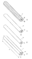
図1(a)〜(d)には、本発明の実施形態に係る結束タイ1〜4が示されている。
結束タイ1は断面矩形状、結束タイ2は断面円形状、結束タイ3は断面楕円形状、結束タイ4は断面星形形状をなし、いずれも芯部11、21、31、41、及び、鞘部12、22、32、42からなる二重構造の結束タイとして構成される。
【0013】
芯部11、21、31、41は、非晶性PETから構成され、鞘部12、22、32、42はLLDPE等のポリエチレンから構成されている。
芯部11、21、31、41の断面形状は、鞘部12、22、32、42の外形形状と相似形をなしており、芯部11、21、31、41の断面における面積比は、芯部/(芯部+鞘部)=50%〜99%の範囲で任意に設定することができる。
また、これらの結束タイ1〜4は、図1(a)の結束タイ1に示されるように、断面積Sと長さ寸法Lが所定の範囲となるように設定されていて、結束タイ1を撚ってその状態を保持するには、L/Sが5〜10000(cm−1)であるのが好ましい。
【0014】
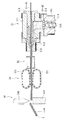
このような結束タイ1〜4は、図2に示される製造装置によって製造され、この製造装置は、押出成形機51、冷却水槽52、引取装置53、およびカッタ54を備えて構成される。
押出成形機51は、予め紡糸された芯線として供給される芯部11〜41を構成する非晶性PETに、溶融樹脂として供給される鞘部12〜42を構成するポリエチレンを被覆する部分であり、クロスヘッド511、ダイ512、及び押出機本体513を備えて構成される。
【0015】
押出機本体513は、ダイ512による押出方向と直交する方向に溶融樹脂を押し出す方向に配置され、バレル514と、このバレル514内に配置されるスクリュ515を備え、ブレーカプレート516を介してクロスヘッド511と接続されている。そして、図示を略したが、原料となるポリエチレンペレットは、ホッパから投入され、バレル514をヒータ等で加熱溶融され、スクリュ515により溶融ポリエチレン樹脂をブレーカプレート516側に搬送される。
クロスヘッド511は、非晶性PET製の芯線の周囲にポリエチレン製の溶融樹脂を被覆する部分であり、内部にニップル518及びニップルホルダ519が設けられている。
【0016】
クロスヘッド511は内部に鞘部12〜42を構成する溶融樹脂が供給される空間を有し、この空間はダイ512に向かうに従って断面が小さくなっている。
ニップル518は、このクロスヘッド511内の空間の略中央に配置され、押出方向先端に向かうにつれて先細り形状となっていて、その先端部分から芯部11〜41を構成する芯線が送り出される。
ニップルホルダ519は、ニップル518を基端側で保持するとともに、芯線を押出方向基端側から供給している。
ダイ512は、芯部11〜41、鞘部12〜42が一体化された結束タイ1〜4を押し出す部分であり、押出成形される結束タイ1〜4の断面形状に応じて複数準備されている。
【0017】
冷却水槽52は、ダイ512から押し出された成形物を冷却固化する部分であり、成形物を内部に溜められた冷却水中に引き通すことにより、短時間で所定温度まで成形物を冷却する。
引取装置53は、成形物を挟持する一対の無限軌道ベルト531を備え、これら一対の無限軌道ベルト531は、押出物の走行方向に沿って回転駆動する。
カッタ54は、押出物を所定の長さ寸法で切断する部分であり、受け台541およびカッタ本体542を備え、押出物はカッタ本体542によって、溶断される。
【0018】
このような製造装置により結束タイ1〜4を製造する場合、まず、押出機本体513のホッパにポリエチレンからなる原料ペレットを投入するとともに、ニップルホルダ519に非晶性PETからなる芯線を供給する。
原料ペレットは、バレル514内で溶融され、スクリュ515によって溶融混練されながら、ブレーカプレート516を介してクロスヘッド511内に供給される。
芯線はニップルホルダ519によりニップル518に送られ、ニップル518の先端部分でポリエチレンからなる樹脂によって被覆され、ダイ512から押し出される。
【0019】
ダイ512からの押出物は、直ちに冷却水槽52によって冷却され、引取装置53を介してカッタ54に供給され、カッタ本体542によって所望の長さに切断され、結束タイ1〜4が製造される。
尚、結束タイ1〜4における芯部11〜41、鞘部12〜42の断面積比は、スクリュ515による溶融樹脂の吐出量と、引取装置53の引取速度を調整することによりある程度変更が可能であり、例えば、樹脂の吐出量を少なくして、引取装置53の引取速度を高くすると、一定の断面積の芯線が速く巻き取られることとなり、これを被覆する鞘部12〜42部分の面積が小さくなる。
ダイ512からの押出速度と引取速度との比として与えられる引取比としては、0.1〜20、好ましくは2〜15である。
【0020】
このような結束タイ1〜4は、図3および図4のような用途に供される。
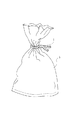
例えば、図3に示されるように、パン等の食品包装袋5の開封後、再び包装袋5の開封部分を閉塞する場合に、包装袋5の開封部分に沿って結束タイ1を巻き付けた後、余った部分を撚って結束して開封部分を閉塞する。
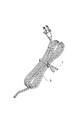
また、図4に示されるように、電気コード6等の余った部分を折り畳み、これをまとめるように結束タイ1を巻き付け、同様に余った部分を撚って結束する。
【0021】
前述のような本実施形態によれば、以下のような効果がある。
結束タイ1〜4をPETで形成することにより、PETの塑性、靱性を利用して撚っても戻りにくい結束タイ1〜4とすることができるため、充分な結束力で包装袋5の開封口や電気コード6を結束することができる。
また、製造時の引取比を調整することにより、芯部11〜41と鞘部12〜42の断面積比を変更することができるため、種々の結束対象に応じた結束タイ1〜4とすることができる。尚、芯部11〜41の面積比を調整する場合は、供給される芯線の径を変更すれば、簡単に調整することができる。
【0022】
さらに、結束タイ1〜4の断面形状をこのような形とすることにより、取り扱い易い結束タイとすることができるうえ、断面形状が単純なので製造効率上も好ましい。
そして、結束タイ1〜4を食品包装袋5の結束タイとして用いることにより、結束タイ1〜4が包装袋5に取り付けられた状態でも、金属等の異物混入検査を行うことができるため、食品包装用の結束タイとして好適である。
また、結束タイ1〜4の鞘部12〜42を構成する樹脂としてポリエチレンを採用することにより、鞘部12〜42にタック性を付与させることができるため、結束タイ1〜4を撚った際、鞘部12〜42のタック性により結束力を向上させることができる。
【0023】
尚、本発明は、前述の実施形態に限定されるものではなく、以下に示すような変形をも含むものである。
前記実施形態では、結束タイ1〜4を構成する樹脂として結晶性または非晶性のPETを採用していたが、本発明はこれに限られない。すなわち、例えば、ポリエステルカーボネート、ポリブチレンテレフタレート、ポリフェニレンオキサイド、ポリカーボネート、ポリフェニレンサルファイド等を芯部の樹脂として採用することができる。
【0024】
また、前記実施形態では、芯部11〜41の材料は予め紡糸された芯線として供給されていたが、本発明はこれに限られない。すなわち、芯部及び鞘部を溶融樹脂とし、共押出成形することにより芯鞘構造の結束タイとしてもよい。尚、芯部をPET、鞘部をポリエチレンとした場合の押出条件としては、例えば、次の表1に示される運転条件で押し出すことができる。また、鞘部には無水マレイン酸等で変性されたポリオレフィンを添加することもできる。
【0025】
【表1】
さらに、前記実施形態では、芯部11〜41の断面形状と鞘部12〜42の断面形状が相似形状とされていたが、本発明はこれに限られず、芯部および鞘部の断面形状を異なるものとしてもよい。
その他、本発明の実施の際の具体的な構造及び形状等は、本発明の目的を達成できる範囲で他の構造等としてもよい。
【0027】
【実施例】
(実施例1)
芯部11の材料として非晶性PET(イーストマンケミカル株式会社 PETG6763)、鞘部41の材料としてポリエチレン(出光石油化学株式会社 LLDPE モアテック 0628D)を用い、断面積比として芯部/(芯部+鞘部)=60%とし、表1に示す条件で共押出成形により結束タイ1を押出成形した。これにより成形された結束タイ1の長さ(L)/断面積(S)比は、10cm/0.04cm2=250cm−1であった。
(実施例2)
断面積比を芯部/(芯部+鞘部)=90%に変更し、それ以外は、実施例1と同様の条件により結束タイ1を押出成形した。
【0028】
(比較例1)
実施例1で用いた芯部に採用した非晶性PETのみからなり、結束タイ1と同じ外形形状の結束タイを押出成形した。押出条件は表1におけるPETの押出条件と同様の条件である。
(比較例2)
実施例1で用いた鞘部に採用したポリエチレンのみからなり、結束タイ1と同じ外形形状の結束タイを押出成形した。
(比較例3)
実施例2における芯部の材料をナイロン6(宇部興産株式会社 UBEナイロン1022)に変更し、断面積比を芯部/(芯部+鞘部)=90%として共押出成形により芯鞘構造の結束タイを成形した。この際の押出条件を表2に示す。
【0029】
【表2】
−評価方法−
(1)結束力の評価
各実施例及び比較例に係る結束タイの両端を合わせてリング状にし、リング部分を3回撚ったものを試験片とし、引張試験機によってクロスヘッドスピード300mm/minで引張り、より戻される強度を測定した。
(2)非復元性の評価
(1)と同様に、各実施例及び比較例に係る結束タイを3回撚ったものを、1分間放置し、1分経過後の状態から非復元性の評価を行った。尚、1分経過後、0〜1回転戻ったものを○、1〜2回転戻ったものを△、2回転以上戻ったものを×として評価した。
【0031】
(3)グリップ力の評価
1kgの分銅を30μmのポリエチレンフィルムで覆い、その開口部を、各実施例及び比較例に係る結束タイで3回撚り封をする。結束タイで封をした部分を把持して分銅を浮かせた状態でこれを観察し、グリップ力の評価を行った。1分以上維持できたものを○、30秒〜1のもの分を△、30秒以下のものを×として評価した。
結果を表3に示す。
【0032】
【表3】
従来の針金を芯材とした結束タイの結束力は、略1000g程度であったので、実施例1及び実施例2はこれに若干及ばないものの、十分な結束力を有することが確認された。また、実施例1及び実施例2の非復元性、グリップ力についても十分なものであることが確認された。
これに対して、PETのみからなる比較例1の場合、結束力は十分なのだが、非復元性及びグリップ力が十分でない。
一方、鞘部樹脂のみからなる比較例2では結束力、非復元性、グリップ力ともに全くなく、結束タイとして用いることは出来ない。
さらに、芯部をナイロン6に変更した比較例3も、ナイロン6の塑性、靱性が十分ではなく、同様に結束タイとして用いることはできない。
【0034】
【発明の効果】
前述のような本発明の結束タイによれば、主鎖にベンゼン環を有する熱可塑性樹脂の塑性、靱性を利用して、充分な結束力を有する結束タイとすることができるという効果がある。
【図面の簡単な説明】
【図1】本発明の第1実施形態に係る結束タイの構造を表す概要斜視図である。
【図2】前期実施形態における結束タイを製造するための製造装置を表す模式図である。
【図3】前記実施形態における結束タイの使用方法を説明するための概要斜視図である。
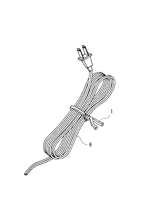
【図4】前記実施形態における結束タイの使用方法を説明するための概要斜視図である。
【符号の説明】
1、2、3、4 結束タイ
11、21、31、41 芯部
12、22、32、42 鞘部[0001]
TECHNICAL FIELD OF THE INVENTION
The present invention relates to a binding tie made of a synthetic resin, and can be suitably applied to, for example, a case of binding an opening of a bag or a case of binding a cord such as a television or a computer with a spring.
[0002]
[Background Art]
Conventionally, as a binding tie for opening the opening of bagged food, binding for the opening of the garbage bag, and for binding cords attached to televisions, computers, etc., with a core made of wire and covered with a thermoplastic resin such as vinyl chloride resin It has been known. Such a binding tie is widely used because it can deform the tie with a small force and maintain a binding holding state for a long time.
[0003]
However, a metal detector may be used to check for contamination of foods and the like, and the above-described binding tie using a wire as a core material cannot be used for bagged foods and the like in which the opening is bound by a binding tie. There is.
In addition, the binding tie using a wire as a core material is composed of a combination of different kinds of materials, such as resin and metal, and has a problem in disposal.
For this reason, a complete resin binding tie that can be used for a metal detector and is easy to dispose of is demanded, and a complete resin binding tie made of high-density polyethylene as a complete resin binding tie (for example, Patent Literature 1), a binding tie (for example, see Patent Literature 2) using a plastic wire as a core material and sandwiched by a flexible tape, a convex portion serving as a core portion, and a flat portion serving as a blade portion. (See, for example, Patent Document 3) is known.
[0004]
[Patent Document 1]
Japanese Utility Model Publication No. 49-11512 (FIGS. 1 and 2)
[Patent Document 2]
Japanese Utility Model Publication No. 60-190654 (FIG. 1)
[Patent Document 3]
JP 2000-95267 A (FIG. 1)
[0005]
[Problems to be solved by the invention]
However, since the binding tie described in Patent Document 1 is made of high-density polyethylene, there is a problem in that the binding tie at the time of binding is not sufficient.
In addition, the binding tie described in Patent Document 2 has a problem in that a flexible tape must be bonded to a core material with an adhesive, which complicates the manufacturing process. Further, after molding, the coating material may be peeled off from the core material.
Furthermore, the binding tie described in Patent Literature 3 has a limited cross-sectional shape, and it is difficult to say that the binding tie can be used for all applications. In addition, by repeating the binding, the joint between the core portion and the blade portion is formed. It may be damaged.
[0006]
SUMMARY OF THE INVENTION An object of the present invention is to provide a binding tie made of a complete resin that can be easily disposed of and easily manufactured, and that is extremely versatile.
[0007]
[Means for Solving the Problems]
In order to achieve the above object, a synthetic resin binding tie of the present invention comprises a core mainly composed of a thermoplastic resin having a benzene ring in a main chain, and a sheath made of a thermoplastic resin covering the core. And characterized in that:
Here, it is preferable to use polyethylene terephthalate (PET) as the thermoplastic resin constituting the core, and it is particularly preferable to use amorphous PET (A-PET, PET-G).
As such amorphous PET, for example, copolymerized PET using terephthalic acid, isophthalic acid or the like as a dicarboxylic acid component and ethylene glycol, 1,4-butanediol, 1,4-cyclohexanedimethanol or the like as a glycol component. Can be mentioned. Among them, copolymerized PET having terephthalic acid as a dicarboxylic acid component and 1,4-cyclohexanedimethanol as a glycol component can be suitably used. As the dicarboxylic acid component, an esterification reaction with the glycol component can be performed using terephthalic acid, or a transesterification reaction with the glycol component can be performed using dimethyl terephthalate.
As the thermoplastic resin used for the sheath, it is preferable to employ a resin having tackiness on the surface when molded. For example, vinyl chloride, ethylene-vinyl acetate copolymer (EVA), low-density polyethylene and the like can be used. Can be adopted.
Furthermore, the cross-sectional shape of the binding tie can adopt various shapes, for example, a rectangular, elliptical, circular, or star-shaped cross section.
[0008]
According to the present invention, since a thermoplastic resin having a benzene ring in the main chain such as polyethylene terephthalate has plasticity and toughness, it is difficult to return even when twisting a binding tie having this as a core, and sufficient binding is achieved. The cord and the opening of the bag can be bound by force.
In addition, by employing a thermoplastic resin having tackiness for the sheath, the binding power can be improved.
Further, amorphous PET has a lower melting point than crystalline PET and is easier to extrude, so that it can be manufactured efficiently by increasing the extrusion speed.
[0009]
By adopting polyethylene for the sheath, it is possible to impart tackiness to the surface of the synthetic resin bundling tie. In addition to polyethylene, the PET does not generate dioxin etc. during incineration and has excellent environmental suitability. Since it is a resin, it becomes easy to perform disposal processing and the like.
In addition, since the binding tie is made of synthetic resin, it can be discarded as plastic waste material, and there is no need for troublesome disposal processing.
[0010]
In the above, it is conceivable that the core and the sheath are integrally formed by co-extrusion.
It is also conceivable that the core portion is formed by spinning in advance, and the sheath portion is formed by extrusion molding so as to cover the core portion.
According to the present invention, when integrally molded by co-extrusion, the core and the sheath can be molded at the same time, so that the production can be simplified.
On the other hand, since the core portion is pre-spun and the sheath portion is covered by extrusion molding, the plasticity, toughness, etc. of the core portion can be adjusted as necessary by stretching or the like, so that the Tie ties can be manufactured.
[0011]
Further, the area ratio in the cross section of the core is preferably core / (core + sheath) = 50% to 99%, more preferably core / (core + sheath) = 60%. ~ 95%.
If the area ratio is 50% or less, the area of the core becomes too small, and the binding tie cannot have plasticity and toughness of the core. On the other hand, when the area ratio is 99% or more, the amount of resin in the sheath becomes too small, and seizure of the sheath resin occurs due to a difference in melting point during extrusion molding, so that extrusion molding cannot be performed well.
[0012]
BEST MODE FOR CARRYING OUT THE INVENTION
Hereinafter, an embodiment of the present invention will be described with reference to the drawings.
1A to 1D show binding ties 1 to 4 according to an embodiment of the present invention.
The binding tie 1 has a rectangular cross-section, the binding tie 2 has a circular cross-section, the binding tie 3 has an elliptical cross-section, and the binding tie 4 has a star-shaped cross-section, all of which have
[0013]
The
The cross-sectional shapes of the
The binding ties 1 to 4 are set so that the cross-sectional area S and the length L are within a predetermined range, as shown in the binding tie 1 in FIG. In order to twist and maintain the state, L / S is preferably 5 to 10000 (cm −1 ).
[0014]
Such binding ties 1 to 4 are manufactured by a manufacturing apparatus shown in FIG. 2, and the manufacturing apparatus includes an
The
[0015]
The
The
[0016]
The
The
The
The
[0017]
The cooling
The take-
The
[0018]
When the binding ties 1 to 4 are manufactured by such a manufacturing apparatus, first, the raw material pellets made of polyethylene are put into the hopper of the extruder
The raw material pellets are melted in the
The core wire is sent to the
[0019]
The extrudate from the
The cross-sectional area ratio of the
The take-off ratio given as the ratio between the extrusion speed and the take-up speed from the
[0020]
Such binding ties 1 to 4 are used for applications as shown in FIGS.
For example, as shown in FIG. 3, after opening the
Also, as shown in FIG. 4, the surplus portion of the
[0021]
According to the above-described embodiment, the following effects can be obtained.
By forming the binding ties 1 to 4 from PET, the binding ties 1 to 4 can be made difficult to return even if twisted by utilizing the plasticity and toughness of PET. Therefore, the
In addition, by adjusting the take-off ratio at the time of manufacturing, the cross-sectional area ratio between the
[0022]
Furthermore, by setting the cross-sectional shape of the binding ties 1 to 4 to such a shape, a binding tie that is easy to handle can be obtained, and since the cross-sectional shape is simple, it is preferable in terms of manufacturing efficiency.
Since the binding ties 1 to 4 are used as the binding ties of the
In addition, by adopting polyethylene as a resin constituting the
[0023]
Note that the present invention is not limited to the above-described embodiment, but includes the following modifications.
In the above embodiment, crystalline or amorphous PET is adopted as the resin constituting the binding ties 1 to 4, but the present invention is not limited to this. That is, for example, polyester carbonate, polybutylene terephthalate, polyphenylene oxide, polycarbonate, polyphenylene sulfide, and the like can be used as the resin of the core.
[0024]
In the above-described embodiment, the material of the
[0025]
[Table 1]
Furthermore, in the said embodiment, although the cross-sectional shape of the core parts 11-41 and the cross-sectional shape of the sheath parts 12-42 were made similar, this invention is not limited to this, but the cross-sectional shape of a core part and a sheath part was changed. It may be different.
In addition, specific structures, shapes, and the like at the time of implementing the present invention may be other structures and the like as long as the object of the present invention can be achieved.
[0027]
【Example】
(Example 1)
Amorphous PET (PETG6763, manufactured by Eastman Chemical Co., Ltd.) was used as the material of the
(Example 2)
The binding tie 1 was extruded under the same conditions as in Example 1 except that the sectional area ratio was changed to core / (core + sheath) = 90%.
[0028]
(Comparative Example 1)
A binding tie made of only the amorphous PET used for the core used in Example 1 and having the same outer shape as the binding tie 1 was extrusion-molded. The extrusion conditions are the same as the PET extrusion conditions in Table 1.
(Comparative Example 2)
A binding tie having the same outer shape as that of the binding tie 1 and made of only polyethylene used for the sheath used in Example 1 was extruded.
(Comparative Example 3)
The material of the core in Example 2 was changed to nylon 6 (UBE Nylon 1022 by Ube Industries, Ltd.), the cross-sectional area ratio was set to 90% for core / (core + sheath) = 90%, and the core-sheath structure was formed by co-extrusion molding. A binding tie was formed. The extrusion conditions at this time are shown in Table 2.
[0029]
[Table 2]
-Evaluation method-
(1) Evaluation of binding force The ends of the binding ties according to each of the examples and the comparative examples were formed into a ring shape by twisting the ring portion three times into a test piece, and a crosshead speed of 300 mm / min was measured by a tensile tester. And the returned strength was measured.
(2) Evaluation of non-restorability As in (1), the binding ties according to each of the examples and the comparative examples were twisted three times, left for 1 minute, and the state after one minute had passed. An evaluation was performed. It should be noted that, after one minute, the sample returned from 0 to 1 rotation was evaluated as ○, the sample returned from 1 to 2 rotations as Δ, and the sample returned from 2 or more rotations was evaluated as ×.
[0031]
(3) Evaluation of grip force A 1 kg weight is covered with a 30 μm polyethylene film, and its opening is twisted and sealed three times with a binding tie according to each example and comparative example. The part sealed with a binding tie was grasped, the weight was floated and observed, and the grip force was evaluated. Those that could be maintained for 1 minute or more were evaluated as ○, those for 30 seconds to 1 were evaluated as Δ, and those for 30 seconds or less were evaluated as x.
Table 3 shows the results.
[0032]
[Table 3]
Since the binding power of the conventional binding tie using a wire as a core material was about 1000 g, Examples 1 and 2 were confirmed to have sufficient binding power, though slightly less than this. Further, it was confirmed that the non-restoring property and the grip force of Example 1 and Example 2 were sufficient.
On the other hand, in the case of Comparative Example 1 consisting only of PET, the binding force is sufficient, but the non-restoring property and the grip force are not sufficient.
On the other hand, in Comparative Example 2 consisting only of the sheath resin, there was no binding power, non-restoring property, or gripping power, and it could not be used as a binding tie.
Further, in Comparative Example 3 in which the core is changed to
[0034]
【The invention's effect】
According to the above-described binding tie of the present invention, there is an effect that a binding tie having a sufficient binding force can be obtained by utilizing the plasticity and toughness of a thermoplastic resin having a benzene ring in a main chain.
[Brief description of the drawings]
FIG. 1 is a schematic perspective view illustrating a structure of a binding tie according to a first embodiment of the present invention.
FIG. 2 is a schematic diagram illustrating a manufacturing apparatus for manufacturing a binding tie according to the first embodiment.
FIG. 3 is a schematic perspective view for explaining a method of using a binding tie in the embodiment.
FIG. 4 is a schematic perspective view for explaining a method of using a binding tie in the embodiment.
[Explanation of symbols]
1, 2, 3, 4
Claims (7)
前記芯部及び鞘部は、共押出成形により一体成形したものであることを特徴とする合成樹脂製結束タイ。The binding tie made of synthetic resin according to claim 1,
A binding tie made of synthetic resin, wherein the core and the sheath are integrally formed by co-extrusion molding.
予め紡糸された芯部を被覆するように前記鞘部を押出成形したものであることを特徴とする合成樹脂製結束タイ。The binding tie made of synthetic resin according to claim 1,
A binding tie made of synthetic resin, wherein the sheath is extruded so as to cover a core that has been spun in advance.
前記芯部は、ポリエチレンテレフタレートを主成分とすることを特徴とする合成樹脂製結束タイ。In the synthetic resin binding tie according to any one of claims 1 to 3,
A binding tie made of a synthetic resin, wherein the core portion is mainly composed of polyethylene terephthalate.
前記ポリエチレンテレフタレートは、非晶性ポリエチレンテレフタレートであることを特徴とする合成樹脂製結束タイ。The synthetic resin binding tie according to claim 4,
The polyethylene terephthalate is amorphous polyethylene terephthalate, wherein the tie is made of synthetic resin.
前記鞘部は、ポリエチレンから構成されていることを特徴とする合成樹脂製結束タイ。The synthetic resin binding tie according to any one of claims 1 to 5,
A binding tie made of a synthetic resin, wherein the sheath is made of polyethylene.
前記芯部の断面における面積比は、芯部/(芯部+鞘部)=50%〜99%であることを特徴とする合成樹脂製結束タイ。The synthetic resin binding tie according to any one of claims 1 to 6,
A binding tie made of a synthetic resin, wherein an area ratio in a cross section of the core is core / (core + sheath) = 50% to 99%.
Priority Applications (1)
| Application Number | Priority Date | Filing Date | Title |
|---|---|---|---|
| JP2003029764A JP2004238038A (en) | 2003-02-06 | 2003-02-06 | Tie made of synthetic resin |
Applications Claiming Priority (1)
| Application Number | Priority Date | Filing Date | Title |
|---|---|---|---|
| JP2003029764A JP2004238038A (en) | 2003-02-06 | 2003-02-06 | Tie made of synthetic resin |
Publications (1)
| Publication Number | Publication Date |
|---|---|
| JP2004238038A true JP2004238038A (en) | 2004-08-26 |
Family
ID=32956852
Family Applications (1)
| Application Number | Title | Priority Date | Filing Date |
|---|---|---|---|
| JP2003029764A Pending JP2004238038A (en) | 2003-02-06 | 2003-02-06 | Tie made of synthetic resin |
Country Status (1)
| Country | Link |
|---|---|
| JP (1) | JP2004238038A (en) |
Cited By (5)
| Publication number | Priority date | Publication date | Assignee | Title |
|---|---|---|---|---|
| CN103842711A (en) * | 2011-08-02 | 2014-06-04 | 力特亿泽公司 | Wraps for bundling objects |
| USD863946S1 (en) | 2008-10-08 | 2019-10-22 | Nite Ize, Inc. | Tie |
| USD863945S1 (en) | 2008-10-08 | 2019-10-22 | Nite Ize, Inc. | Tie |
| CN110482018A (en) * | 2019-07-26 | 2019-11-22 | 邰国芳 | A kind of band and its production technology |
| US10549895B2 (en) | 2008-10-08 | 2020-02-04 | Nita Ize, Inc. | Tie wrap for bundling objects |
-
2003
- 2003-02-06 JP JP2003029764A patent/JP2004238038A/en active Pending
Cited By (6)
| Publication number | Priority date | Publication date | Assignee | Title |
|---|---|---|---|---|
| USD863946S1 (en) | 2008-10-08 | 2019-10-22 | Nite Ize, Inc. | Tie |
| USD863945S1 (en) | 2008-10-08 | 2019-10-22 | Nite Ize, Inc. | Tie |
| US10549895B2 (en) | 2008-10-08 | 2020-02-04 | Nita Ize, Inc. | Tie wrap for bundling objects |
| CN103842711A (en) * | 2011-08-02 | 2014-06-04 | 力特亿泽公司 | Wraps for bundling objects |
| CN103842711B (en) * | 2011-08-02 | 2018-06-08 | 力特亿泽公司 | Wraps for bundling objects |
| CN110482018A (en) * | 2019-07-26 | 2019-11-22 | 邰国芳 | A kind of band and its production technology |
Similar Documents
| Publication | Publication Date | Title |
|---|---|---|
| JP2813994B2 (en) | Coreless twist tie and manufacturing method thereof | |
| US7011879B1 (en) | Composite polymeric twist tie | |
| EP1674405A1 (en) | Non-metallic twist tie | |
| US6372068B1 (en) | Composite polymeric twist tie | |
| EP0221879A2 (en) | Non-metallic polymeric twist tie | |
| JPH0485017A (en) | Film of easy tear properties and pouch manufactured thereof | |
| GB1592310A (en) | Glass fibre reinforced thermoplastic resin moulding material | |
| EP3090296A1 (en) | Binder film system | |
| WO1991002042A1 (en) | Thermoplastic web and process for manufacturing same | |
| JP5902007B2 (en) | Optical fiber cable and optical fiber cable manufacturing method | |
| JP2012128236A (en) | Optical cable | |
| JP3577553B2 (en) | Shrink wrap | |
| JP3048540B2 (en) | Tying strap | |
| JP4338241B2 (en) | Plastic bundling tie and manufacturing method thereof | |
| JP4889285B2 (en) | Manufacturing method of parts for chuck in biodegradable chuck bag. | |
| JP2003504530A (en) | Method and apparatus for the production of bristles | |
| JP2008273625A (en) | Package | |
| JPH07205275A (en) | Stick made of synthetic resin and apparatus for producing the same | |
| JPWO1999055595A1 (en) | Shrink-wrapped | |
| JPH05345398A (en) | Heat-sealable cavity-containing polyester film | |
| JPH111263A (en) | Twist tie | |
| JPS5964335A (en) | Reinforced polymer product | |
| CA1044661A (en) | Binding material | |
| JP2000253931A (en) | brush | |
| JP2004122565A (en) | Nonwoven laminate |
Legal Events
| Date | Code | Title | Description |
|---|---|---|---|
| A621 | Written request for application examination |
Effective date: 20050908 Free format text: JAPANESE INTERMEDIATE CODE: A621 |
|
| RD02 | Notification of acceptance of power of attorney |
Free format text: JAPANESE INTERMEDIATE CODE: A7422 Effective date: 20070703 |
|
| RD02 | Notification of acceptance of power of attorney |
Effective date: 20070810 Free format text: JAPANESE INTERMEDIATE CODE: A7422 |
|
| A977 | Report on retrieval |
Free format text: JAPANESE INTERMEDIATE CODE: A971007 Effective date: 20080125 |
|
| A131 | Notification of reasons for refusal |
Free format text: JAPANESE INTERMEDIATE CODE: A131 Effective date: 20080129 |
|
| A02 | Decision of refusal |
Free format text: JAPANESE INTERMEDIATE CODE: A02 Effective date: 20080527 |