JP2004238040A - Cartoning machine - Google Patents
Cartoning machine Download PDFInfo
- Publication number
- JP2004238040A JP2004238040A JP2003029973A JP2003029973A JP2004238040A JP 2004238040 A JP2004238040 A JP 2004238040A JP 2003029973 A JP2003029973 A JP 2003029973A JP 2003029973 A JP2003029973 A JP 2003029973A JP 2004238040 A JP2004238040 A JP 2004238040A
- Authority
- JP
- Japan
- Prior art keywords
- carton
- flat
- flat carton
- pad
- turret
- Prior art date
- Legal status (The legal status is an assumption and is not a legal conclusion. Google has not performed a legal analysis and makes no representation as to the accuracy of the status listed.)
- Granted
Links
- 230000007246 mechanism Effects 0.000 claims abstract description 163
- 230000002441 reversible effect Effects 0.000 claims abstract description 51
- 238000004381 surface treatment Methods 0.000 claims abstract description 36
- 238000012546 transfer Methods 0.000 claims description 10
- 239000000470 constituent Substances 0.000 claims description 2
- 238000009434 installation Methods 0.000 abstract description 4
- 238000013461 design Methods 0.000 abstract description 2
- 230000003247 decreasing effect Effects 0.000 abstract 1
- 238000000034 method Methods 0.000 description 9
- 238000010586 diagram Methods 0.000 description 5
- 238000004519 manufacturing process Methods 0.000 description 5
- 238000012856 packing Methods 0.000 description 5
- 238000003780 insertion Methods 0.000 description 4
- 230000037431 insertion Effects 0.000 description 4
- 238000012545 processing Methods 0.000 description 4
- 210000000078 claw Anatomy 0.000 description 3
- 239000011347 resin Substances 0.000 description 3
- 229920005989 resin Polymers 0.000 description 3
- 238000013459 approach Methods 0.000 description 2
- 239000002537 cosmetic Substances 0.000 description 2
- 238000004049 embossing Methods 0.000 description 2
- 239000000463 material Substances 0.000 description 2
- 229920006311 Urethane elastomer Polymers 0.000 description 1
- 238000007599 discharging Methods 0.000 description 1
- 230000000694 effects Effects 0.000 description 1
- 230000000717 retained effect Effects 0.000 description 1
- 238000004904 shortening Methods 0.000 description 1
- 239000000126 substance Substances 0.000 description 1
- 230000001360 synchronised effect Effects 0.000 description 1
Images




Landscapes
- Supplying Of Containers To The Packaging Station (AREA)
- Making Paper Articles (AREA)
Abstract
Description
【0001】
【発明の属する技術分野】
本発明は、平らに折り畳まれたカートン(平カートン)を起函するカートニングマシーンに関する。特には、逆折り機構を備えたコンパクトなカートニングマシーンに関する。
【0002】
【従来技術】
平カートンを起函するカートニングマシーンは、化粧品や薬品などの瓶やチューブ状の製品の梱包用に使用されている。近年、透明又は半透明な樹脂製のカートンを使用したいという要求がある。樹脂製のカートンはこしが強く、起函した際に元の平らな状態に戻ろうとし、折り目が付きにくい。このため、このような樹脂製の平カートンを起函する際には、一度起函させた状態から、逆方向に折り返し(逆折りし)、折り目の両側へのこしを相殺して起函する必要がある。
また、吸湿や変形した紙カートンの起函を容易に行えることが必要である。
【0003】
このような逆折り機構を備えたカートニングマシーンとして、例えば、平カートンの搬送経路中に固定傾斜ガイドや上下ストッパを設けるものがある(後記の特許文献1参照)。この例では、固定傾斜ガイドによって、搬送経路の断面形状が搬送方向に沿って変化する。平カートンは吸引カップで吸引されて、この搬送経路を通過しながら上下ストッパで断面における2つの角が摺動しながら案内され、その際にカートンが逆折りされながら起函される。
【0004】
また、カートンストッカーの手前に、1枚の平カートンを取り出す機構と、取り出した平カートンを逆折りする機構を同一面上に連続して備えたものがある(後記の特許文献2参照)。この例では、平カートンは取り出し機構によって取り出された後、逆折り機構において両側から挟んで起函される。
【0005】
【特許文献1】
特公平5−36295号公報
【特許文献2】
特開昭63−191725号公報
【0006】
【発明が解決しようとする課題】
ところで、化粧品のような製品には、製品の多様化や販売サイクルの短期化にともなって、多くの種類を少量だけ生産するものが増えてきている。このため、よりコンパクトでポータブルであり、生産効率の良いカートニングマシーンが求められている。
【0007】
さらに、カートンには、梱包時に、製品のロット番号や製造年月日などの情報を含んだ数字やバーコードを、カートンの正面や背面に印字や押印、打刻、貼付する(表面処置する)ものがある。このような情報は製品の製造日時などによって変化するため、あるいは、中に詰める製品によって変わるため、カートン製作時に印字することはできず、製品の梱包時にリアルタイムで印字する必要がある。この際には、処置されるカートンの裏当てが必要になり、平カートンの状態で処置することが望ましい。
【0008】
しかし、上述の特許文献1に開示されているカートニングマシーンは、カートンの搬送経路の形状が一定であり、寸法や形状が一定のカートンを大量処理する場合に適しているといえるが、多種多様のカートンの少量処理には向いていない。
【0009】
特許文献2に開示されているカートニングマシーンも、取出し機構と逆折り機構が一体に設けられているため、カートンの逆折り中には、次の平カートンを取り出すために取出し機構を動かすことができず、カートンの組立能率が悪くなる。また、両機構の設計の自由度も低い。そして、両機構は同一面上に配置されているため、取り出されたカートンを逆折りする際に、カートンの前方及び後方に空間を設けるために取出し機構のストロークを長くする必要があり、マシーンの設置面積が大きくなる。
【0010】
本発明は上記の課題に鑑みてなされたものであって、カートンの取出し、逆折り、さらには表面処置を効率よく行うことができるコンパクトなカートニングマシーンを提供することを目的とする。
【0011】
【課題を解決するための手段】
上記の問題点を解決するため、本発明の第1のカートニングマシーンは、 折り畳まれた状態のカートン(平カートン)を重ねて収容するカートンストッカー、及び、該カートンストッカーから前記平カートンを1枚ずつ取り出す取出機構、を有する平カートン払出し階と、 払い出された平カートンを下又は上に移送する移送部と、 移送された平カートンを起こした後に逆折りする逆折り機構、及び、起きた状態のカートン(起カートン)にフラップ折や他の処置を施す機構を含む起函階と、を備えることを特徴とする。
【0012】
カートンストッカー及び取出し機構と、逆折り機構を上下に独立して配置することができるため、両機構の動作や設計の自由度や独立度が高くなる。例えば、一つ前のカートンの逆折り中に、次のカートンを取り出すことができ、処理能率が高くなる。また、マシーンの設置面積を小さくできる。なお、起函階のカートン移送方式は特に限定されず、ターレット式、コンベア式、サイクル式などを使用できる。上記移送部は、平カートンを下に移送する場合はガイドしながら落下させることですむが、上に移送する場合はリフト機構を設ける。
【0013】
本発明の第2のカートニングマシーンは、 折り畳まれた状態のカートン(平カートン)を重ねて収容するカートンストッカー、及び、該カートンストッカーから前記平カートンを1枚ずつ取り出す取出機構、を有する平カートン払出し階と、 払い出された平カートンを下又は上に移送する第1の移送部と、 移送された平カートンの正面又は背面に処置を施す表面処処置機構を有する表面処置階と、 表面処置された平カートンを下又は上に移送する第2の移送部と、 移送された平カートンを起こした後に逆折りする逆折り機構、及び、起きた状態のカートン(起カートン)にフラップ折や他の処置を施す機構を含む起函階と、を備えることを特徴とする。
【0014】
ここで、 前記表面処置機構が、前記平カートンの正面及び背面の両方に当接して処置を施すものとすることができる。
バーコードの貼り付けや印字、打刻、捺印、エンボス加工などの表面処置を行う表面処置階も、カートンストッカー及び取出し機構と逆折り機構との間に独立して配置することができる。このような表面処置は、処置されるカートンを固定する裏当てが必要になる。このため、平カートンを起こしてからでは、裏当てを位置させることが困難であるが、本発明においては、1枚の平カートンの状態で表面処置機構に搬送されるため、カートンの正面側と背面側の両面から平カートンに処置(裏当てと表面処置)を行うことができる。
なお、本発明のカートニングマシーンにおいては、処置階の階数を2、3階として全体を4階、5階、あるいはそれ以上とすることができる。
【0015】
本発明の第3のカートニングマシーンは、 4以上の構成面を有するカートンの逆折り機構を有するカートニングマシーンであって、 折り畳まれた状態の前記カートン(平カートン)の一つの構成面(第1面)を吸着する第1のパッドと、 前記第1面と対向する面(第2面)を吸着する第2のパッドと、 前記第1のパッドと第2のパッドとを相対的に運動させて前記平カートンを起こした後に逆折りするパッド移動機構を具備することを特徴とする。
第1のパッドと第2のパッドを相対的に運動させる方法としては、例えば、固定した一方のパッドに対して他方のパッドを円運動させる方法がある。この方法において、円の半径を調整する機構を設ければ、様々なサイズの平カートンの逆折りに対応できる。このため、多種の平カートンに対応できるカートニングマシーンを提供できる。
【0016】
【発明の実施の形態】
以下、図面を参照しつつ説明する。
まず、平カートンの構造を説明する。
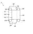
図8は、平カートンの一例の平面図である。この図は、後述するカートンストッカーに並んでいる状態を、カートンストッカーの進行方向の前側から見た図である。
この例の平カートンCは、起函されたときに直方体状となる本体を有する。本体の図の奥側の面を正面C1、この正面にC1に対向する手前側の面を背面C2、右側の面を右側面C3、左側の面を左側面C4とする。後述する例のカートニングマシーンでは、バーコードや数字の印字等の表面処置は、背面C2に施されるが、これに限定されるものではない。正面C1の上縁には上フラップC5が設けられ、下縁には下フラップC6が設けられている。上フラップC5の上縁には上差し込みフラップC7、下フラップC6の下縁には下差し込みフラップC8が設けられている。また、左右側面の上縁には上サイドフラップC9、下縁には下サイドフラップC10が設けられている。
【0017】
図1は、本発明の実施の形態に係るカートニングマシーンの全体構成を模式的に説明する正面図である。
図2は、図1のカートニングマシーンの平面図である。
このカートニングマシーン1は、図1の上部に示すカートンストッカー10を備える。カートンストッカー10の先には、平カートンCの移動経路に沿って、順に、カートンストッカー10、平カートン取出し機構20、その下の表面処置機構30、さらにその下の逆折り機構50とターレット200が配置されている。ターレット200の周囲には、図2に示すように、下サイドフラップ再折込機構100、下フラップ予備折り機構110、下フラップ成形機構120、上フラップ予備折折り機構130、上フラップ成形機構140、カートン排出機構150が配置されている。
【0018】
図1に示すように、このカートニングマシーン1は3階建ての構造を有する。最も上の階(3F)は、カートンストッカー10と平カートン取出し機構20が位置する平カートン払出し階である。真中の階(2F)は、表面処置機構30が位置する表面処置階である。最も下の階(1F)は、逆折り機構50を含めたその他の機構が位置する起函階である。
そして、図1から分かるように、平カートン取出し機構20と、表面処置機構30と、逆折り機構50とは縦方向に並んで位置する。平カートン取出し機構20と表面処置機構30との間、及び、表面処置機構30と逆折り機構50との間には、各々縦に延びるガイド(移送部)220、230が配置されている。
【0019】
図2に示すように、下サイドフラップ再折込機構100、下フラップ予備折り機構110、下フラップ成形機構120、上フラップ予備折り機構130、上フラップ成形機構140、カートン排出機構150は、起函階上で、ターレット200の周囲に、作業経路に沿って配置されている。
【0020】
図1に示すように、ターレット200は上下に配置された上ターレット板201と下ターレット板203からなる。上下ターレット板201、201は同じ形状で、各ターレット板の外周には、起函されたカートン(起カートン)がはまり込む複数(一例で12個)のポケット207(図2参照)が形成されている。ターレット200は、ベースフレーム210に内蔵された回転機構を有し、両ターレット板は、共通の回転軸205に沿って同期で間欠的に回転する。この例では、ターレット200は、図の矢印で示す反時計方向に回転する。
ターレット200の回転にともなって、ポケット207に入れられた起カートンは、下サイドフラップ再折込機構100、下フラップ予備折り機構110、下フラップ成形機構120、上フラップ予備折り機構130、上フラップ成形機構140、カートン排出機構150で順に処理が施される。
【0021】
以下、カートニングマシーン1の詳細な構造について説明する。
まず、上下方向に3階建てに並んだカートンストッカー10及び平カートン取出し機構20と、表面処置機構30と、逆折り機構50の構造について詳細に説明する。
図3は、カートンストッカー、平カートン取出し機構、表面処置機構、逆折り機構を模式的に示す斜視図である。
図の最上部(3F、平カートン払出し階)に位置するカートンストッカー10は、平カートンCを多数重ねて保持するホルダ11を備える。ホルダ11は約400mmのスペースを有する。ホルダ11の、カートン払出し方向の最も手前側の面11aは開いており、この面(払出し面)からカートンが払い出される。同面11aにはカートンが倒れないように保持する爪13が設けられている。
【0022】
平カートン取出し機構20はベース21上に配置され、カートンストッカー10と同じ平面上(3F)に位置する。
同機構20は、カートンストッカー11の払出し面11aに対向するように配置された2つのバキュームパッド23と、同パッド23を駆動するエアシリンダ(図示されず)を備える。バキュームパッド23はエアシリンダのヘッドプレート25に固定されて、ターレット径方向に駆動される。
【0023】
エアシリンダがターレット径方向を外方向に延びると、バキュームパッド23はカートンストッカー10に保持されている平カートンの最も手前の平カートンCの背面に接触する。そして同パッド23を真空引きすると、平カートンCはバキュームパッド23に吸着して固定される。次に、エアシリンダを引き込むと、同パッド23に吸着された平カートンCが爪13で反らされながら手前方向に引き出される。そして、吸着パッド23のバキュームを解除すると、平カートンCがパッド23から外れ、1枚の平カートンCが取り出される。
【0024】
平カートン取出し機構20のベース21には、平カートンCの幅よりやや広い幅のポケット27が形成されている。エアシリンダは、バキュームパッド23に吸着した平カートンCをポケット27の真上まで引き込む。ベース21は、ポケット27の両側面で、ベースフレーム210から立設する一対のポール28に取り付けられている。固定ガイド220は断面がコの字状で、開いた面が対向するように配置されている。なお、固定ガイド220のベース21から上の部分は、平カートンに当たらないように断面形状がL字型となっている。
なお、固定ガイド220は、カートンの寸法に応じて幅を調整できる。
【0025】
ポケット27の真上まで引き出された平カートンCは、バキュームパッド23のバキュームが解除されると同パッド23から外れる。そして、ポケット27から固定ガイド220に沿って落下する。
【0026】
固定ガイド220の表面処置階(2F)の床の高さ位置には、ストッパ221が設けられている。ストッパ221は、エアシリンダ(図示されず)により、固定ガイド220間の位置と、同ガイドから離れた位置との間を、ターレットの径方向に移動可能である。ストッパ221が固定ガイド220間に位置したとき、固定ガイド220に沿って落下した平カートンCが同ストッパ221に受け止められる。
【0027】
ストッパ221の上方の表面処置階(2F)上には、表面処置機構30が設けられている。この例の表面処置機構30は、印字部31と、同部31と対向する背面当てプレート33と、バーコードリーダ35を含む。
印字部31と背面当てプレート33は、固定ガイド220の間で、ターレット径方向に対向するように配置されている。印字部31はエアシリンダ37のヘッドプレート37aに固定されて、ターレットの径方向に駆動される。背面当てプレート33は、例えば70°ウレタンゴム製で、エアシリンダ39のヘッドプレート39aに固定されて、ターレットの径方向に駆動される。印字部31と背面当てプレート33は、同じ高さ位置に位置し、両エアシリンダ37、39が延びると、印字部31と背面当てプレート33は当接する。
【0028】
平カートンCがストッパ221上に受け止められた状態で、エアシリンダ37をターレット径方向を外方向、エアシリンダ39をターレット径方向を内方向に延ばすと、平カートンCは印字部31と背面当てプレート33に挟まれる。そして、背面当てプレート33によって固定された平カートンCの正面に対して、印字部31によって同カートンの背面に印字処置がなされる。
【0029】
また、ベース21の下面にはバーコードリーダ35が取り付けられている。このバーコードリーダ35は、固定ガイド220に沿ってベース21からストッパ221に落下する途中の平カートンCの背面に記されたバーコードを読み取る。
【0030】
ストッパ221の下方の起函階(1F)の部分には、固定ガイド220の下方に連続する一対の可動ガイド230が配置されている。ストッパ221が、ターレットの径方向を外方向に駆動されると、ストッパ221上に留められていた平カートンCは、固定ガイド220及び可動ガイド230に案内されてストッパ233上に落下する。ストッパ233は、ターレット200の外側に固定されている。
【0031】
各可動ガイド230は、ターレットの周方向を互いに接近するよう、及び、離れるように各々エアシリンダ231で駆動される。各エアシリンダ231が延びて各可動ガイド230が接近すると、平カートンCをターレットの周方向に挟んで同カートンを立てた状態に維持し、エアシリンダ231が引き込まれると、各可動ガイド230が離れて平カートンCを開放する。
【0032】
ターレット面上の起函階(1F)上には、逆折り機構50が設けられている。
図4、図5、図6、図7を参照して、逆折り機構の構造を説明する。
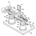
図4は、逆折り機構の主構造を示す斜視図である。
図5は、逆折り機構の一部の位置関係を示す図であり、図5(A)は部分正面図、図5(B)は部分側面図である。
図6は、逆折り機構による逆折りの仕組みを説明する図である。
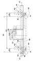
図7は、逆折り機構による各部の動きを説明する図である。
【0033】
逆折り機構50は、図5(B)に示すように、2つの固定側バキュームパッド51と2つの可動側バキュームパッド53を備える。各パッド51、53は、可動ガイド230の間で、ターレット径方向において対向するように配置されている。固定側バキュームパッド51はエアシリンダ55のヘッドプレート55aに固定されて、ターレットの径方向に駆動される。可動側バキュームパッド53は、エアシリンダ57のヘッドプレート57aに固定されて、ターレットの径方向に駆動される。
【0034】
また、図5(A)に示すように、固定側バキュームパッド51は、平カートンCの背面C2に位置し、可動側バキュームパッド53は正面C1に位置する。ここで、各バキュームパッド51、53のターレット周方向間の位置関係や高さ方向の位置関係は特に限定されない。
【0035】
可動ガイド間230に平カートンCが維持された状態で、各バキュームパッドのエアシリンダ55、57が延びると、固定側バキュームパッド51は、平カートンの背面C2に接触し、可動側バキュームパッド53は同カートンの正面C1に接触する。そして、両バキュームパッド51、53を真空引きすると、平カートンの背面及び正面は、各々固定側バキュームパッド51及び可動側バキュームパッド53に吸着して固定される。
【0036】
可動側バキュームパッド53には、同パッドを固定側バキュームパッド51に対して円運動させて平カートンを起こした後に逆折りするパッド移動機構が備えられている。
図6を参照して、このパッド移動機構による平カートンの逆折りの仕組みを説明する。
図6(A)は、平カートンCが可動ガイド230間に維持された状態で、固定側バキュームパッド51が、平カートンCの背面C2に吸着し、可動側バキュームパッド53が同カートンの正面C1に吸着している状態を示す。
【0037】
この状態から、図6(B)、(C)、(D)に一連に示すように、固定側バキュームパッド51に対して、可動側バキュームパッド53を時計方向に円運動させる。平カートンCの背面C2を基準面Rとする。この円運動において、固定側バキュームパッド51は固定されているため、常に基準面R上にある。
【0038】
図6(B)に示すように、可動側バキュームパッド53を約1/8周時計方向に円運動させると、カートンの両側面C3、C4が背面C2(基準面R)に対して起き上がる。このとき、側面C4と基準面Rとのなす角θは約45°である。そして、図6(C)に示すように、可動側バキュームパッド53を最初の状態から約1/4周時計方向に円運動させると、カートンの両側面C3、C4は背面C2に対して完全に起き上がる(起函する)。このとき、側面C4と基準面Rとのなす角θは約90°である。
【0039】
そして、図6(D)に示すように、可動側バキュームパッド53をさらに時計方向に円運動させると、カートンの横断面は平行四辺形となり、側面C4と基準面Rとのなす角θが鈍角となる。この動きによりカートンCが逆折りされる。
【0040】
その後、図6(E)に示すように、可動側バキュームパッド53のバキュームを解除すると、逆折りされたカートンCは元の平カートンの状態に戻ろうとして、図6(C)に示すようなほぼ起函した状態となる。そして、固定側バキュームパッド51のエアシリンダ55を引き込むと、起函したカートンCがガイド(図示されず)に従いターレット200のポケット207に入り込む。
【0041】
この図から分かるように、可動側バキュームパッド53が円運動する可能な回転角度範囲を、カートンの側面C4と基準面Rとのなす角θで表すと、平カートンの状態である0°から、平カートンの折り畳み方向と逆方向に折り畳んだ状態である180°までとなる。そして、この回転角度範囲内で起函に供される角度範囲は0〜90°、逆折りに供される角度範囲は90〜180°である。逆折りのための角度は、カートンの材質や形状によって異なる。例えば、カートンがこしの強い材料で作製されている場合は、逆折り角度を大きくする。したがって、カートンストッカーで起函するカートンに応じて角度を予め決めておく。この角度を調整する方法については後述する。
【0042】
図6から分かるように、可動側バキュームパッド53の円運動の半径は、平カートンCの左右側面C3、C4の幅である。つまり、パッド移動機構は、可動側バキュームパッド53を固定側バキュームパッド51に対して、平カートンCの側面C3、C4の幅を半径として円運動させる機構である。
【0043】
次に、図4を参照してパッド移動機構の構造を説明する。
パッド移動機構は、主に、可動側バキュームパッド53駆動用のエアシリンダ57が固定された水平方向に延びるバー59と、同バー59の両端で回転可能に連結された水平方向に延びる2つのフレーム61と、同フレーム61を同期で回転させるラックピニオン機構63とを備える。
【0044】
次に、図7を参照してバー59とフレーム61との関係について説明する。
パッド移動機構において、バー59の両端の回転中心A1間の距離D1と、各フレーム61の回転中心A2間の距離D2は等しい。また、バー59の各回転中心A1と各フレーム61の回転中心A2間の距離D3は等しい。すなわち、バー59及び両フレーム61は、バー59の各回転中心A1と各フレーム61の回転中心A2を回転中心とする平行クランク機構を構成している。
【0045】
この平行クランク機構によるバーの円運動について説明する。
可動側バキュームパッド駆動用エアシリンダ57は、バー59のほぼ中央に固定されている。バー59の両端は、回転軸A1で各々フレーム61に回転可能に連結されている。両フレーム61は、ラックピニオン機構63(詳細後述)によって回転軸A2に沿って同期で水平面上を回転する(回転した状態を図の二点鎖線で示す)。両フレーム61が回転すると、両フレーム61に回転可能に連結されているバー59は、回転軸A1上で回転しながら円運動する。詳細には、バー59は、回転半径を距離D3(バー59の各回転中心A1と各フレーム61の回転中心A2間の距離)として、各フレーム61の回転中心A2を通る線L1と平行に円運動する。
【0046】
次に、両フレーム61の回転機構について図4を参照して詳細に説明する。
両フレーム61の回転機構は、ラックピニオン機構63であり、エアシリンダ71によって伸縮運動するラック65と、同ラック65と噛み合う2つのピニオン67を備える。各ピニオン67は、ベースフレーム210上に立設する2つの支柱69に回転可能に内蔵されている。各ピニオン67の回転軸67aは支柱69の上面から突き出て、各フレーム61の下面の各々同じ位置に回転不能に固定されている。したがって、フレーム61の回転軸A2はピニオン67の回転軸67aとなる。
ラック65がエアシリンダ71で駆動されて水平運動すると、同ラック65に噛み合うピニオン67が回転し、同時にフレーム61が回転軸A2を中心にして水平面上を回転する。各フレーム1の回転範囲は、ラック65の移動距離によって決められる。
【0047】
各フレーム61の上面には、同フレームの長手方向に延びる溝73が形成されている。
図の右側のフレーム61の溝73には、ネジ75が回転可能に配置されている。ネジ75は、溝73の両端で軸受(図示されず)によって固定され、ハンドル75aを回転させることにより溝73内で回転する。ネジ75の溝73内の部分にはコマ77が噛み合っている。ネジ75を回転させると、コマ77は溝73内をフレーム61の長手方向に移動する(コマの移動に伴う作用については後述する)。コマ77の上面には、ロックナット79が固定されている。ロックナット79は、軸受81を介してバー59の右端に回転可能に連結している。したがって、バー59の一方の回転軸A1は軸受81の回転軸である。
一方、図の左側のフレーム61の溝73には、コマ77が直接嵌め込まれている。コマ77は溝73内をフレーム61の長手方向に移動する。コマ77の上面には、ロックナット79が固定されている。ロックナット79は、軸受81を介してバー59の左端に回転可能に連結している。したがって、バー59の他方の回転軸A1は軸受81の回転軸である。
【0048】
パッド移動機構について、図4を参照して説明する。
パッド移動機構の初期状態を、平カートンの正面及び背面に各バキュームパッドが吸着している状態(図6(A)参照)とする。図4はこの初期状態を示し、バー59と各フレーム61は直線上に並び、ラック65は、図の最も左方向まで引き込まれている。
エアシリンダ71が伸ばされて、ラック65が図の右方向に駆動されると、同ラック65に噛み合うピニオン67は時計方向に回転する。そして、各ピニオン67の回転軸67aに固定されている各フレーム61は回転軸A2に沿って時計方向に水平面上を同期で回転する。すると、バー59はフレーム61に対して回転軸A1上で回転しながら時計方向に円運動する。この円運動の半径は、バーの回転中心とフレームの回転中心間の距離D3であり、バー59は、フレームの回転中心間の線L1と平行に動く(図7参照)。なお、バー59の円運動範囲は、フレーム61の回転角度、すなわち、ラック65の移動距離で決められる。
【0049】
可動側バキュームパッド53はエアシリンダ57を介してバー59に固定されているため、バキュームパッド51の円運動における回転半径は、バー59の円運動の回転半径D3と等しく、バーの各回転中心A1とフレームの回転中心A2間の距離D3である。
【0050】
一方、図6で示したように、可動側バキュームパッド53の円運動の回転半径D3は、平カートンCの側面C3、C4の幅である。そこで、バーの各回転中心A1とフレームの回転中心A2間の距離D3を、平カートンの左右側面の幅と等しくなるように調整する。このとき、フレーム61の回転中心A2の位置は不変であるため、バー59の回転中心A1の位置を変える。バー59の回転中心A1の位置を変えるには、右側のフレーム61の溝73内のネジ75を回転させて、溝73内のコマ77を所定量移動させる。すると、コマ77の移動は、バー59を介して左側のコマ77に伝わり、このコマ77もフレーム61の溝73内を移動する。これにより、両コマ77の移動距離を自動的に等しくすることできる。両コマ77が所定量移動した後、両ロックナット79を締めて両コマ77を位置決めする。
【0051】
なお、各フレーム61を時計方向に回転させるには、ラック65が図の右方向に移動するようにエアシリンダ71を駆動させる。ラック65の先方には、適正な逆折角度に位置決めするストッパ85が設けられている。
【0052】
また、上述のように、逆折り角度は平カートンのこしの強さに応じて調整する。逆折り角度は、つまり、フレーム61の回転角度であり、同角度はピニオン67の回転角度と等しく、ラック65の移動距離で決められる。そこで、ラックピニオン機構63の歯数やピッチを基にして、フレームの回転角度から移動距離を求めることができる。
【0053】
逆折り以降の起カートンの組立方法について説明する。
平カートンが逆折り機構で逆折りされた後、図6(E)に示すように、可動側バキュームパッド53のバキュームを解除すると、カートンは逆折りの状態から元に戻ろうとしてほぼ起函した状態になる。こうして平カートンが起函した後、固定側バキュームパッド51のエアシリンダを引き込むと、同パッド51に吸着した起カートンは、ターレット200の一つのポケット207(図2参照)に入り込み、完全に起函する。ポケット207の形状は起カートンの断面形状とほぼ等しいので、起カートンはポケット207内に位置決めされる。
なお、カートンの形状や寸法が変わった場合には、その形状や寸法に合わせたポケットを有するターレットに取り替える。
【0054】
その後、ターレット200が回転軸205上を間欠的に回転する。ターレット200が反時計方向にほぼ3/4周する間に、平カートンの逆折り以降の組立工程が施される。
ポケット207に入れられた起カートンは、ターレット200の回転によって下サイドフラップ再折込機構100に進み、そこで停止して下サイドフラップが90°以上折り曲げられる。その後、ターレット200が回転し、回転中に梱包される製品が人手で起カートンに供給される。
【0055】
その後、下フラップ予備折機構110に進み、そこで停止して、下差し込みフラップの先端が折られる。その後、ターレット200が回転して下フラップ成形機構120及び上フラップ予備折り機構130に進み、そこで停止し、カートンの下フラップが成形されるとともに、上フラップの差し込みフラップの先端が折られる。そして、ターレット200が回転して上カートン成形機構140に進み、そこで停止し、カートンの上フラップが成形され、梱包が終了する。最後に、カートン排出部150から排出される。
【0056】
下サイドフラップ再折込機構100、下フラップ予備折り機構110、下フラップ成形機構120、上フラップ予備折り機構130、上フラップ成形機構140、カートン排出機構150は、既存の機構を使用できる。
【0057】
なお、上述のように、ターレット200は間欠的に回転する。このとき、各作業を連続して行うために、同じターレット径方向位置にある、カートンストッカー10、カートン取出し機構20、表面処置機構30、逆折り機構50と、下サイドフラップ再折込機構100と、下フラップ予備折り機構110と、下フラップ成形機構120と、上フラップ予備折り機構130と、上フラップ成形機構140と、カートン排出機構150とは、ターレット200の周方向に等間隔(この例では、ターレット中心において45°の中心角度)おきに配置されている。そして、ターレット200の間欠運転の移動時間、停止時間を等しくしてターレット200の円周方向において行われる各作業を同期させているとともに、平カートン取出し機構20、表面処置機構30、逆折り機構50において行われる作業も同期させている。
【0058】
なお、この例では、カートンをターレット200の回転によって移送したが、移送方式は特に限定されず、ターレット式、コンベア式、サイクル式などを使用できる。
【0059】
【発明の効果】
以上の説明から明らかなように、本発明によれば、カートンの取出し、表面処置、逆折りを上下方向に独立して配置したことにより、各々の機構を独立して作動させることができるため、作業効率を高くでき、マシーンの設置面積も小さくできる。また、平カートンの状態で表面処置を行うことができるとともに、カートンの正面と背面の空間が開いているため、マシーンを大型化することなく印字の際の裏当てを配置する空間を設けることができる。
【図面の簡単な説明】
【図1】本発明の実施の形態に係るカートニングマシーンの全体構成を模式的に説明する正面図である。
【図2】図1のカートニングマシーンの平面図である。
【図3】カートンストッカー、平カートン取出し機構、表面処置機構、逆折り機構を模式的に示す斜視図である。
【図4】逆折り機構の主構造を示す斜視図である。
【図5】逆折り機構の一部の位置関係を示す図であり、図5(A)は部分正面図、図5(B)は部分側面図である。
【図6】逆折り機構による逆折りの仕組みを説明する図である。
【図7】逆折り機構による各部の動きを説明する図である。
【図8】平カートンの一例の平面図である。
【符号の説明】
1 カートニングマシーン 10 カートンストッカー
11 ホルダ 13 爪
20 平カートン取出し機構 21 ベース
23 バキュームパッド 25 ヘッドプレート
27 ポケット 28 ポール
30 表面処置機構 31 印字部
33 背面当てプレート 35 バーコードリーダ
37、39 エアシリンダ
50 逆折り機構 51 固定側バキュームパッド
53 可動側バキュームパッド 55、57 エアシリンダ
59 バー 61 フレーム
63 ラックピニオン機構 71 エアシリンダ
65 ラック 67 ピニオン
69 支柱 73 溝
75 ネジ 77 コマ
79 ロックナット 81 軸受
85 ストッパ 100 下サイドフラップ再折込機構
110 下フラップ予備折り機構 120 下フラップ成形機構
130 上フラップ予備折り機構 140 上フラップ成形機構
150 カートン排出機構 200 ターレット
201 上ターレット板 203 下ターレット板
205 回転軸 207 ポケット
220 固定ガイド 221 ストッパ
223 ストッパ 230 可動ガイド
231 エアシリンダ[0001]
TECHNICAL FIELD OF THE INVENTION
The present invention relates to a cartoning machine for producing a flat folded carton (flat carton). In particular, it relates to a compact cartoning machine having a reverse folding mechanism.
[0002]
[Prior art]
Cartoning machines that produce flat cartons are used for packing bottles and tube-shaped products such as cosmetics and chemicals. In recent years, there is a demand to use a transparent or translucent resin carton. Resin cartons are strong, tend to return to their original flat condition when they are raised, and are not easily creased. For this reason, when raising such a flat carton made of resin, it is necessary to return to the reverse direction (reverse folding) from the state where it has been raised once, and cancel the strain on both sides of the fold before raising it. There is.
In addition, it is necessary to be able to easily absorb moisture and open a deformed paper carton.
[0003]
As a cartoning machine provided with such a reverse folding mechanism, for example, there is a cartoning machine provided with a fixed inclined guide and a vertical stopper in a transport path of a flat carton (see
[0004]
In addition, there is a mechanism provided with a mechanism for taking out one flat carton and a mechanism for reversely folding the taken out flat carton on the same surface in front of the carton stocker (see Patent Document 2 described later). In this example, the flat carton is picked up from both sides by the reverse folding mechanism after being taken out by the take-out mechanism.
[0005]
[Patent Document 1]
Japanese Patent Publication No. 5-36295
[Patent Document 2]
JP-A-63-191725
[0006]
[Problems to be solved by the invention]
By the way, with the diversification of products and the shortening of the sales cycle, many products, such as cosmetics, produce many types in small quantities. For this reason, a cartoning machine that is more compact, portable and has high production efficiency is required.
[0007]
Furthermore, at the time of packing, a number or a bar code containing information such as the lot number of the product and the date of manufacture is printed, stamped, stamped, and affixed to the front and back of the carton (surface treatment) at the time of packing. There is something. Since such information changes depending on the production date and time of the product, or changes depending on the product to be packed therein, it cannot be printed at the time of carton production, but must be printed in real time at the time of packing the product. In this case, it is necessary to back up the carton to be treated, and it is desirable to treat in a flat carton.
[0008]
However, the cartoning machine disclosed in
[0009]
The cartoning machine disclosed in Patent Document 2 also has a take-out mechanism and a reverse folding mechanism provided integrally, so that during the reverse folding of the carton, the take-out mechanism can be moved to take out the next flat carton. No, the efficiency of carton assembly is reduced. Also, the degree of freedom in designing both mechanisms is low. And since both mechanisms are arranged on the same surface, when the taken-out carton is reversely folded, it is necessary to lengthen the stroke of the taking-out mechanism in order to provide a space in front of and behind the carton. The installation area increases.
[0010]
The present invention has been made in view of the above problems, and an object of the present invention is to provide a compact cartoning machine capable of efficiently performing carton removal, reverse folding, and surface treatment.
[0011]
[Means for Solving the Problems]
In order to solve the above problems, a first cartoning machine of the present invention comprises: a carton stocker for storing folded cartons (flat cartons) in a stack; and one flat carton from the carton stockers. A flat carton payout floor having a take-out mechanism for taking out each one, a transfer unit for transferring the flat carton discharged downward or upward, a reverse folding mechanism for reversely folding the transported flat carton after raising, and And a starting floor including a mechanism for performing a flap folding or other treatment on the carton in the state (raised carton).
[0012]
Since the carton stocker, the take-out mechanism, and the reverse folding mechanism can be arranged vertically independently, the freedom and independence of the operation and design of both mechanisms are increased. For example, during the reverse folding of the previous carton, the next carton can be taken out, thereby increasing the processing efficiency. Further, the installation area of the machine can be reduced. In addition, the carton transfer method of the raising floor is not particularly limited, and a turret type, a conveyor type, a cycle type, or the like can be used. The transfer unit may be guided and dropped when transferring the flat carton downward, but a lift mechanism is provided when transferring the flat carton upward.
[0013]
A second cartoning machine of the present invention is a flat carton having a carton stocker for stacking and storing folded cartons (flat cartons), and a removing mechanism for taking out the flat cartons one by one from the carton stocker. A dispensing floor, a first transfer unit for transferring the dispensed flat carton down or up, a surface treatment floor having a surface treatment mechanism for performing treatment on the front or back of the transferred flat carton, and a surface treatment A second transfer unit for transferring the flat carton that has been moved downward or upward, a reverse folding mechanism that reverses the flat carton that has been transferred and then reversely folds, and a flap folding or the like for the carton (raised carton) in the raised state. And a raising floor including a mechanism for performing the above-mentioned treatment.
[0014]
Here, the surface treatment mechanism may perform treatment by contacting both the front and the back of the flat carton.
A surface treatment floor for performing surface treatment such as sticking, printing, embossing, stamping, embossing, etc. of a bar code can also be independently disposed between the carton stocker and the take-out mechanism and the reverse folding mechanism. Such surface treatment requires a backing to secure the carton being treated. For this reason, it is difficult to position the backing after raising the flat carton. However, in the present invention, since the single flat carton is conveyed to the surface treatment mechanism, it is difficult to position the backing. The treatment (backing and surface treatment) can be performed on the flat carton from both sides on the back side.
In the cartoning machine of the present invention, the number of treatment floors may be two or three, and the whole number may be four, five, or more.
[0015]
A third cartoning machine of the present invention is a cartoning machine having a carton reverse folding mechanism having four or more constituent surfaces, wherein one carton (flat carton) of the carton (flat carton) in a folded state is provided. A first pad that adsorbs a first surface, a second pad that adsorbs a surface (a second surface) opposite to the first surface, and a relative movement of the first pad and the second pad And a pad moving mechanism that reversely folds the flat carton after raising the flat carton.
As a method of relatively moving the first pad and the second pad, for example, there is a method of making the other pad circularly move with respect to one fixed pad. In this method, if a mechanism for adjusting the radius of the circle is provided, it is possible to cope with reverse folding of flat cartons of various sizes. For this reason, it is possible to provide a cartoning machine that can handle various types of flat cartons.
[0016]
BEST MODE FOR CARRYING OUT THE INVENTION
Hereinafter, description will be made with reference to the drawings.
First, the structure of the flat carton will be described.
FIG. 8 is a plan view of an example of a flat carton. This figure is a view of the state of being arranged in a carton stocker, which will be described later, viewed from the front side in the traveling direction of the carton stocker.
The flat carton C of this example has a rectangular parallelepiped main body when opened. The front side of the drawing of the main body is referred to as a front face C1, the front side facing the front face C1 is referred to as a back face C2, the right side face as a right side face C3, and the left side face as a left side face C4. In a cartoning machine of an example to be described later, a surface treatment such as printing of a barcode or a number is performed on the back surface C2, but is not limited to this. An upper flap C5 is provided at an upper edge of the front face C1, and a lower flap C6 is provided at a lower edge. An upper insertion flap C7 is provided at an upper edge of the upper flap C5, and a lower insertion flap C8 is provided at a lower edge of the lower flap C6. An upper side flap C9 is provided at the upper edge of the left and right side surfaces, and a lower side flap C10 is provided at the lower edge.
[0017]
FIG. 1 is a front view schematically illustrating the entire configuration of the cartoning machine according to the embodiment of the present invention.
FIG. 2 is a plan view of the cartoning machine of FIG.
The
[0018]
As shown in FIG. 1, the
Then, as can be seen from FIG. 1, the flat
[0019]
As shown in FIG. 2, the lower side
[0020]
As shown in FIG. 1, the
With the rotation of the
[0021]
Hereinafter, a detailed structure of the
First, the structures of the
FIG. 3 is a perspective view schematically showing a carton stocker, a flat carton removal mechanism, a surface treatment mechanism, and a reverse folding mechanism.
The
[0022]
The flat
The
[0023]
When the air cylinder extends outward in the radial direction of the turret, the
[0024]
In the
The width of the fixed
[0025]
The flat carton C pulled out just above the
[0026]
A
[0027]
The
The printing unit 31 and the
[0028]
With the flat carton C being received on the
[0029]
A
[0030]
A pair of
[0031]
Each
[0032]
A
The structure of the reverse folding mechanism will be described with reference to FIG. 4, FIG. 5, FIG. 6, and FIG.
FIG. 4 is a perspective view showing a main structure of the reverse folding mechanism.
FIGS. 5A and 5B are views showing a partial positional relationship of the reverse folding mechanism. FIG. 5A is a partial front view, and FIG. 5B is a partial side view.
FIG. 6 is a diagram illustrating the mechanism of reverse folding by the reverse folding mechanism.
FIG. 7 is a diagram illustrating the movement of each unit by the reverse folding mechanism.
[0033]
The
[0034]
Further, as shown in FIG. 5A, the fixed-
[0035]
When the
[0036]
The movable-
With reference to FIG. 6, a mechanism of reverse folding of the flat carton by the pad moving mechanism will be described.
FIG. 6A shows a state in which the flat carton C is held between the
[0037]
From this state, as shown in a series in FIGS. 6B, 6C, and 6D, the movable-
[0038]
As shown in FIG. 6B, when the movable-
[0039]
Then, as shown in FIG. 6D, when the movable-
[0040]
Thereafter, as shown in FIG. 6 (E), when the vacuum of the movable-
[0041]
As can be seen from this figure, when the rotation angle range in which the movable-
[0042]
As can be seen from FIG. 6, the radius of the circular motion of the movable-
[0043]
Next, the structure of the pad moving mechanism will be described with reference to FIG.
The pad moving mechanism mainly includes a horizontally extending
[0044]
Next, the relationship between the
In the pad moving mechanism, the distance D1 between the rotation centers A1 at both ends of the
[0045]
The circular motion of the bar by the parallel crank mechanism will be described.
The movable-side vacuum pad driving
[0046]
Next, the rotation mechanism of both
The rotation mechanism of both
When the
[0047]
On the upper surface of each
A screw 75 is rotatably arranged in the
On the other hand, the top 77 is directly fitted into the
[0048]
The pad moving mechanism will be described with reference to FIG.
It is assumed that the initial state of the pad moving mechanism is a state in which each vacuum pad is attracted to the front and back of the flat carton (see FIG. 6A). FIG. 4 shows this initial state, in which the
When the
[0049]
Since the movable-
[0050]
On the other hand, as shown in FIG. 6, the rotation radius D3 of the circular motion of the movable-
[0051]
To rotate each
[0052]
As described above, the reverse folding angle is adjusted according to the strength of the flat carton. The reverse folding angle is the rotation angle of the
[0053]
A method of assembling the raised carton after the reverse folding will be described.
After the flat carton is reversely folded by the reverse folding mechanism, as shown in FIG. 6 (E), when the vacuum of the movable-
When the shape or size of the carton changes, the turret having a pocket according to the shape or size is replaced.
[0054]
Thereafter, the
The raised carton placed in the
[0055]
Thereafter, the process proceeds to the lower flap
[0056]
Existing mechanisms can be used for the lower side
[0057]
Note that, as described above, the
[0058]
In this example, the carton was transferred by rotating the
[0059]
【The invention's effect】
As is clear from the above description, according to the present invention, the removal of the carton, surface treatment, and reverse folding are arranged independently in the vertical direction, so that each mechanism can be operated independently, Work efficiency can be increased, and the installation area of the machine can be reduced. In addition, the surface treatment can be performed in a flat carton state, and since the front and back spaces of the carton are open, it is possible to provide a space for arranging a backing for printing without increasing the size of the machine. it can.
[Brief description of the drawings]
FIG. 1 is a front view schematically illustrating the entire configuration of a cartoning machine according to an embodiment of the present invention.
FIG. 2 is a plan view of the cartoning machine of FIG.
FIG. 3 is a perspective view schematically showing a carton stocker, a flat carton removal mechanism, a surface treatment mechanism, and a reverse folding mechanism.
FIG. 4 is a perspective view showing a main structure of the reverse folding mechanism.
5A and 5B are diagrams showing a partial positional relationship of the reverse folding mechanism, FIG. 5A is a partial front view, and FIG. 5B is a partial side view.
FIG. 6 is a diagram illustrating a mechanism of reverse folding by the reverse folding mechanism.
FIG. 7 is a diagram illustrating the movement of each unit by the reverse folding mechanism.
FIG. 8 is a plan view of an example of a flat carton.
[Explanation of symbols]
1
11
20 Flat
23
27
30 surface treatment mechanism 31 printing unit
33
37, 39 Air cylinder
50
53
59
63 Rack and
65
69
75
79
85
110 Lower flap preliminary folding mechanism 120 Lower flap forming mechanism
130 Upper flap
150
201
205
220
223
231 Air cylinder
Claims (4)
払い出された平カートンを下又は上に移送する移送部と、
移送された平カートンを起こした後に逆折りする逆折り機構、及び、起きた状態のカートン(起カートン)にフラップ折や他の処置を施す機構を含む起函階と、
を備えることを特徴とするカートニングマシーン。A flat carton payout floor having a carton stocker for stacking and storing folded cartons (flat carton), and a take-out mechanism for taking out the flat cartons one by one from the carton stocker;
A transfer unit for transferring the dispensed flat carton below or above,
A reversing mechanism for reversing after raising the transported flat carton, and a raising floor including a mechanism for performing flap folding or other treatment on the raised carton (raised carton);
A cartoning machine comprising:
払い出された平カートンを下又は上に移送する第1の移送部と、
移送された平カートンの正面又は背面に処置を施す表面処置機構を有する表面処置階と、
表面処置された平カートンを下又は上に移送する第2の移送部と、
移送された平カートンを起こした後に逆折りする逆折り機構、及び、起きた状態のカートン(起カートン)にフラップ折や他の処置を施す機構を含む起函階と、
を備えることを特徴とするカートニングマシーン。A flat carton payout floor having a carton stocker for stacking and storing folded cartons (flat carton), and a take-out mechanism for taking out the flat cartons one by one from the carton stocker;
A first transfer unit for transferring the dispensed flat carton downward or upward;
A surface treatment floor having a surface treatment mechanism for applying treatment to the front or back of the transferred flat carton;
A second transfer unit for transferring the surface-treated flat carton downward or upward;
A reversing mechanism for reversing after raising the transported flat carton, and a raising floor including a mechanism for performing flap folding or other treatment on the raised carton (raised carton);
A cartoning machine comprising:
折り畳まれた状態の前記カートン(平カートン)の一つの構成面(第1面)を吸着する第1のパッドと、
前記第1面と対向する面(第2面)を吸着する第2のパッドと、
前記第1のパッドと第2のパッドとを相対的に運動させて前記平カートンを起こした後に逆折りするパッド移動機構を具備することを特徴とするカートニングマシーン。A cartoning machine having a carton reverse folding mechanism having four or more constituent surfaces,
A first pad for adsorbing one component surface (first surface) of the carton (flat carton) in a folded state;
A second pad for adsorbing a surface (second surface) facing the first surface;
A cartoning machine, comprising: a pad moving mechanism configured to relatively move the first pad and the second pad to raise the flat carton and then reversely fold the carton.
Priority Applications (1)
| Application Number | Priority Date | Filing Date | Title |
|---|---|---|---|
| JP2003029973A JP3693998B2 (en) | 2003-02-06 | 2003-02-06 | Cartoning machine |
Applications Claiming Priority (1)
| Application Number | Priority Date | Filing Date | Title |
|---|---|---|---|
| JP2003029973A JP3693998B2 (en) | 2003-02-06 | 2003-02-06 | Cartoning machine |
Publications (3)
| Publication Number | Publication Date |
|---|---|
| JP2004238040A true JP2004238040A (en) | 2004-08-26 |
| JP2004238040A5 JP2004238040A5 (en) | 2005-07-14 |
| JP3693998B2 JP3693998B2 (en) | 2005-09-14 |
Family
ID=32956992
Family Applications (1)
| Application Number | Title | Priority Date | Filing Date |
|---|---|---|---|
| JP2003029973A Expired - Lifetime JP3693998B2 (en) | 2003-02-06 | 2003-02-06 | Cartoning machine |
Country Status (1)
| Country | Link |
|---|---|
| JP (1) | JP3693998B2 (en) |
Cited By (16)
| Publication number | Priority date | Publication date | Assignee | Title |
|---|---|---|---|---|
| EP1628159A2 (en) | 2004-08-18 | 2006-02-22 | Fuji Photo Film Co., Ltd. | Chemical amplification resist composition and pattern-forming method using the same |
| JP2009012832A (en) * | 2007-07-06 | 2009-01-22 | Nagano Yoshida Kogyo Kk | Opening device |
| JP2013523560A (en) * | 2010-03-29 | 2013-06-17 | オトール | Method and apparatus for transferring cutouts for packaging boxes |
| CN103350793A (en) * | 2013-07-16 | 2013-10-16 | 王前宏 | Carton folding device of full-automatic carton lifting handle eyeleting machine |
| JP2014234233A (en) * | 2013-06-05 | 2014-12-15 | 東洋自動機株式会社 | Bag mouth opening device for bags which are continuously transferred |
| JP2016074139A (en) * | 2014-10-06 | 2016-05-12 | 株式会社木田鉄工所 | Processing inspection device |
| JP2018090265A (en) * | 2016-11-30 | 2018-06-14 | 株式会社小松メカニカル | Cartoning apparatus and cartoning system |
| CN108839861A (en) * | 2018-05-15 | 2018-11-20 | 温州职业技术学院 | Full-automatic paper box packing machine based on modularized design |
| JP2019034770A (en) * | 2017-08-18 | 2019-03-07 | 株式会社イシダ | Box manufacturing device |
| JP2019043569A (en) * | 2017-08-30 | 2019-03-22 | 株式会社フジシール | Carton assembly device |
| CN111421885A (en) * | 2019-01-10 | 2020-07-17 | 广东鸿铭智能股份有限公司 | Full-automatic wine box machine |
| CN114083829A (en) * | 2021-11-26 | 2022-02-25 | 中科天工(武汉)智能技术有限公司 | Method and device for folding edges of gummed paper material |
| CN114671065A (en) * | 2020-12-24 | 2022-06-28 | 上海万尔芯智能科技有限公司 | Welding rod boxing machine |
| CN114735309A (en) * | 2022-05-10 | 2022-07-12 | 红云红河烟草(集团)有限责任公司 | Lining paper embossed seal small-size adjustment tool for packing machine and packing machine |
| WO2023070849A1 (en) * | 2021-10-29 | 2023-05-04 | 歌尔股份有限公司 | Pre-bending device |
| CN116588413A (en) * | 2023-06-16 | 2023-08-15 | 山东诠道科技有限公司 | Automatic packaging equipment for light heat-insulating bricks |
-
2003
- 2003-02-06 JP JP2003029973A patent/JP3693998B2/en not_active Expired - Lifetime
Cited By (22)
| Publication number | Priority date | Publication date | Assignee | Title |
|---|---|---|---|---|
| EP2031445A2 (en) | 2004-08-18 | 2009-03-04 | FUJIFILM Corporation | Chemical amplification resist composition and pattern-forming method using the same |
| EP1628159A2 (en) | 2004-08-18 | 2006-02-22 | Fuji Photo Film Co., Ltd. | Chemical amplification resist composition and pattern-forming method using the same |
| JP2009012832A (en) * | 2007-07-06 | 2009-01-22 | Nagano Yoshida Kogyo Kk | Opening device |
| JP2013523560A (en) * | 2010-03-29 | 2013-06-17 | オトール | Method and apparatus for transferring cutouts for packaging boxes |
| US10315794B2 (en) | 2013-06-05 | 2019-06-11 | Toyo Jidoki Co., Ltd. | Bag mouth opening device for continuously conveyed bags |
| JP2014234233A (en) * | 2013-06-05 | 2014-12-15 | 東洋自動機株式会社 | Bag mouth opening device for bags which are continuously transferred |
| CN103350793A (en) * | 2013-07-16 | 2013-10-16 | 王前宏 | Carton folding device of full-automatic carton lifting handle eyeleting machine |
| JP2016074139A (en) * | 2014-10-06 | 2016-05-12 | 株式会社木田鉄工所 | Processing inspection device |
| JP2018090265A (en) * | 2016-11-30 | 2018-06-14 | 株式会社小松メカニカル | Cartoning apparatus and cartoning system |
| JP6996734B2 (en) | 2017-08-18 | 2022-01-17 | 株式会社イシダ | Box making device |
| JP2019034770A (en) * | 2017-08-18 | 2019-03-07 | 株式会社イシダ | Box manufacturing device |
| JP2019043569A (en) * | 2017-08-30 | 2019-03-22 | 株式会社フジシール | Carton assembly device |
| JP6996909B2 (en) | 2017-08-30 | 2022-01-17 | 株式会社フジシール | Carton assembly equipment |
| CN108839861A (en) * | 2018-05-15 | 2018-11-20 | 温州职业技术学院 | Full-automatic paper box packing machine based on modularized design |
| CN111421885A (en) * | 2019-01-10 | 2020-07-17 | 广东鸿铭智能股份有限公司 | Full-automatic wine box machine |
| CN114671065A (en) * | 2020-12-24 | 2022-06-28 | 上海万尔芯智能科技有限公司 | Welding rod boxing machine |
| CN114671065B (en) * | 2020-12-24 | 2024-04-26 | 上海万尔芯智能科技有限公司 | Welding rod boxing machine |
| WO2023070849A1 (en) * | 2021-10-29 | 2023-05-04 | 歌尔股份有限公司 | Pre-bending device |
| CN114083829A (en) * | 2021-11-26 | 2022-02-25 | 中科天工(武汉)智能技术有限公司 | Method and device for folding edges of gummed paper material |
| CN114735309A (en) * | 2022-05-10 | 2022-07-12 | 红云红河烟草(集团)有限责任公司 | Lining paper embossed seal small-size adjustment tool for packing machine and packing machine |
| CN116588413A (en) * | 2023-06-16 | 2023-08-15 | 山东诠道科技有限公司 | Automatic packaging equipment for light heat-insulating bricks |
| CN116588413B (en) * | 2023-06-16 | 2023-11-14 | 山东诠道科技有限公司 | Automatic packaging equipment for light heat-insulating bricks |
Also Published As
| Publication number | Publication date |
|---|---|
| JP3693998B2 (en) | 2005-09-14 |
Similar Documents
| Publication | Publication Date | Title |
|---|---|---|
| JP3693998B2 (en) | Cartoning machine | |
| CN103359320B (en) | Novel opening, packing and sealing integrated machine for carton | |
| RU2334668C2 (en) | Method and device for producing vessels packages | |
| EP0425226B1 (en) | Continuous to intermittent feeding interface | |
| US3683755A (en) | Tray forming apparatus | |
| JP3615896B2 (en) | Two-stage packaging equipment, carton pick-up equipment and carton box forming equipment | |
| AU2006291073B2 (en) | Carton opening device capable of opening cartons of differing geometries | |
| JP6228766B2 (en) | Accumulator | |
| KR200362787Y1 (en) | Paper remove apparatus | |
| US5228674A (en) | Sheet feeding apparatus | |
| JP2017200830A (en) | Packaging apparatus | |
| JP4613192B2 (en) | Opening device | |
| EP4288278A1 (en) | Assembly and method for the automated folding of corners of a box | |
| JPS59186870A (en) | Counter ejector in machine for manufacturing can made of corrugated cardboard | |
| CN116834373B (en) | An automatic forming machine for bottom-type drawer boxes and gift boxes | |
| KR100418354B1 (en) | Automatic packing machine of partially packed paperboard | |
| JPH0742711Y2 (en) | Box making equipment | |
| EP0441871A4 (en) | A sheet feeding apparatus | |
| JP7277704B2 (en) | Box making device | |
| JP3897465B2 (en) | Paperboard supply device and paperboard supply method in multipack machine | |
| JP2523897Y2 (en) | Seam flap bending device | |
| CN114313427A (en) | Soap packaging machine | |
| EP1068946B1 (en) | Method and apparatus for erecting an open cardboard box | |
| JP2949858B2 (en) | Packaging equipment | |
| JP2004250072A (en) | Cartoning machine |
Legal Events
| Date | Code | Title | Description |
|---|---|---|---|
| A521 | Request for written amendment filed |
Free format text: JAPANESE INTERMEDIATE CODE: A523 Effective date: 20041112 |
|
| A621 | Written request for application examination |
Free format text: JAPANESE INTERMEDIATE CODE: A621 Effective date: 20041112 |
|
| A871 | Explanation of circumstances concerning accelerated examination |
Free format text: JAPANESE INTERMEDIATE CODE: A871 Effective date: 20041112 |
|
| A975 | Report on accelerated examination |
Free format text: JAPANESE INTERMEDIATE CODE: A971005 Effective date: 20050131 |
|
| A131 | Notification of reasons for refusal |
Free format text: JAPANESE INTERMEDIATE CODE: A131 Effective date: 20050203 |
|
| A521 | Request for written amendment filed |
Free format text: JAPANESE INTERMEDIATE CODE: A523 Effective date: 20050329 |
|
| TRDD | Decision of grant or rejection written | ||
| A01 | Written decision to grant a patent or to grant a registration (utility model) |
Free format text: JAPANESE INTERMEDIATE CODE: A01 Effective date: 20050614 |
|
| A61 | First payment of annual fees (during grant procedure) |
Free format text: JAPANESE INTERMEDIATE CODE: A61 Effective date: 20050622 |
|
| R150 | Certificate of patent or registration of utility model |
Ref document number: 3693998 Country of ref document: JP Free format text: JAPANESE INTERMEDIATE CODE: R150 Free format text: JAPANESE INTERMEDIATE CODE: R150 |
|
| FPAY | Renewal fee payment (event date is renewal date of database) |
Free format text: PAYMENT UNTIL: 20090701 Year of fee payment: 4 |
|
| R250 | Receipt of annual fees |
Free format text: JAPANESE INTERMEDIATE CODE: R250 |
|
| FPAY | Renewal fee payment (event date is renewal date of database) |
Free format text: PAYMENT UNTIL: 20100701 Year of fee payment: 5 |
|
| R250 | Receipt of annual fees |
Free format text: JAPANESE INTERMEDIATE CODE: R250 |
|
| FPAY | Renewal fee payment (event date is renewal date of database) |
Free format text: PAYMENT UNTIL: 20110701 Year of fee payment: 6 |
|
| R250 | Receipt of annual fees |
Free format text: JAPANESE INTERMEDIATE CODE: R250 |
|
| R250 | Receipt of annual fees |
Free format text: JAPANESE INTERMEDIATE CODE: R250 |
|
| FPAY | Renewal fee payment (event date is renewal date of database) |
Free format text: PAYMENT UNTIL: 20130701 Year of fee payment: 8 |
|
| R250 | Receipt of annual fees |
Free format text: JAPANESE INTERMEDIATE CODE: R250 |
|
| FPAY | Renewal fee payment (event date is renewal date of database) |
Free format text: PAYMENT UNTIL: 20130701 Year of fee payment: 8 |
|
| FPAY | Renewal fee payment (event date is renewal date of database) |
Free format text: PAYMENT UNTIL: 20140701 Year of fee payment: 9 |
|
| R250 | Receipt of annual fees |
Free format text: JAPANESE INTERMEDIATE CODE: R250 |
|
| R250 | Receipt of annual fees |
Free format text: JAPANESE INTERMEDIATE CODE: R250 |
|
| R250 | Receipt of annual fees |
Free format text: JAPANESE INTERMEDIATE CODE: R250 |
|
| R250 | Receipt of annual fees |
Free format text: JAPANESE INTERMEDIATE CODE: R250 |
|
| R250 | Receipt of annual fees |
Free format text: JAPANESE INTERMEDIATE CODE: R250 |
|
| R250 | Receipt of annual fees |
Free format text: JAPANESE INTERMEDIATE CODE: R250 |
|
| R250 | Receipt of annual fees |
Free format text: JAPANESE INTERMEDIATE CODE: R250 |
|
| S531 | Written request for registration of change of domicile |
Free format text: JAPANESE INTERMEDIATE CODE: R313531 |
|
| R250 | Receipt of annual fees |
Free format text: JAPANESE INTERMEDIATE CODE: R250 |
|
| R350 | Written notification of registration of transfer |
Free format text: JAPANESE INTERMEDIATE CODE: R350 |
|
| R250 | Receipt of annual fees |
Free format text: JAPANESE INTERMEDIATE CODE: R250 |
|
| R250 | Receipt of annual fees |
Free format text: JAPANESE INTERMEDIATE CODE: R250 |
|
| EXPY | Cancellation because of completion of term |