JP2004239975A - Lamp holder - Google Patents
Lamp holder Download PDFInfo
- Publication number
- JP2004239975A JP2004239975A JP2003026289A JP2003026289A JP2004239975A JP 2004239975 A JP2004239975 A JP 2004239975A JP 2003026289 A JP2003026289 A JP 2003026289A JP 2003026289 A JP2003026289 A JP 2003026289A JP 2004239975 A JP2004239975 A JP 2004239975A
- Authority
- JP
- Japan
- Prior art keywords
- lamp
- opening
- lamp holder
- rib
- outside
- Prior art date
- Legal status (The legal status is an assumption and is not a legal conclusion. Google has not performed a legal analysis and makes no representation as to the accuracy of the status listed.)
- Pending
Links
- 239000012634 fragment Substances 0.000 claims description 11
- 238000011144 upstream manufacturing Methods 0.000 claims description 2
- 230000000903 blocking effect Effects 0.000 claims 1
- 230000002093 peripheral effect Effects 0.000 abstract description 23
- 239000011521 glass Substances 0.000 abstract description 10
- 230000005855 radiation Effects 0.000 description 17
- 238000001816 cooling Methods 0.000 description 13
- 230000000694 effects Effects 0.000 description 9
- 230000009191 jumping Effects 0.000 description 8
- 229910052751 metal Inorganic materials 0.000 description 8
- 239000002184 metal Substances 0.000 description 8
- 239000000463 material Substances 0.000 description 7
- 238000004519 manufacturing process Methods 0.000 description 6
- 229920005989 resin Polymers 0.000 description 6
- 239000011347 resin Substances 0.000 description 6
- 238000010586 diagram Methods 0.000 description 5
- 238000004880 explosion Methods 0.000 description 5
- 229910001507 metal halide Inorganic materials 0.000 description 5
- 150000005309 metal halides Chemical class 0.000 description 5
- 229910052782 aluminium Inorganic materials 0.000 description 4
- XAGFODPZIPBFFR-UHFFFAOYSA-N aluminium Chemical compound [Al] XAGFODPZIPBFFR-UHFFFAOYSA-N 0.000 description 4
- RYGMFSIKBFXOCR-UHFFFAOYSA-N Copper Chemical compound [Cu] RYGMFSIKBFXOCR-UHFFFAOYSA-N 0.000 description 3
- 229910052802 copper Inorganic materials 0.000 description 3
- 239000010949 copper Substances 0.000 description 3
- 230000004048 modification Effects 0.000 description 3
- 238000012986 modification Methods 0.000 description 3
- 230000000191 radiation effect Effects 0.000 description 3
- XKRFYHLGVUSROY-UHFFFAOYSA-N Argon Chemical compound [Ar] XKRFYHLGVUSROY-UHFFFAOYSA-N 0.000 description 2
- 239000004696 Poly ether ether ketone Substances 0.000 description 2
- 239000004734 Polyphenylene sulfide Substances 0.000 description 2
- 230000007423 decrease Effects 0.000 description 2
- 239000007789 gas Substances 0.000 description 2
- 229920002530 polyetherether ketone Polymers 0.000 description 2
- 229920000069 polyphenylene sulfide Polymers 0.000 description 2
- 239000000047 product Substances 0.000 description 2
- 238000007789 sealing Methods 0.000 description 2
- GQKYKPLGNBXERW-UHFFFAOYSA-N 6-fluoro-1h-indazol-5-amine Chemical compound C1=C(F)C(N)=CC2=C1NN=C2 GQKYKPLGNBXERW-UHFFFAOYSA-N 0.000 description 1
- RZVAJINKPMORJF-UHFFFAOYSA-N Acetaminophen Chemical compound CC(=O)NC1=CC=C(O)C=C1 RZVAJINKPMORJF-UHFFFAOYSA-N 0.000 description 1
- 229910001111 Fine metal Inorganic materials 0.000 description 1
- YCKRFDGAMUMZLT-UHFFFAOYSA-N Fluorine atom Chemical compound [F] YCKRFDGAMUMZLT-UHFFFAOYSA-N 0.000 description 1
- 239000004677 Nylon Substances 0.000 description 1
- VYPSYNLAJGMNEJ-UHFFFAOYSA-N Silicium dioxide Chemical compound O=[Si]=O VYPSYNLAJGMNEJ-UHFFFAOYSA-N 0.000 description 1
- 229910052786 argon Inorganic materials 0.000 description 1
- XQPRBTXUXXVTKB-UHFFFAOYSA-M caesium iodide Chemical compound [I-].[Cs+] XQPRBTXUXXVTKB-UHFFFAOYSA-M 0.000 description 1
- 238000007599 discharging Methods 0.000 description 1
- 238000005516 engineering process Methods 0.000 description 1
- 239000000835 fiber Substances 0.000 description 1
- 229910052731 fluorine Inorganic materials 0.000 description 1
- 239000011737 fluorine Substances 0.000 description 1
- 230000017525 heat dissipation Effects 0.000 description 1
- 229920006015 heat resistant resin Polymers 0.000 description 1
- 238000010438 heat treatment Methods 0.000 description 1
- QSHDDOUJBYECFT-UHFFFAOYSA-N mercury Chemical compound [Hg] QSHDDOUJBYECFT-UHFFFAOYSA-N 0.000 description 1
- 229910052753 mercury Inorganic materials 0.000 description 1
- 239000000203 mixture Substances 0.000 description 1
- 238000000465 moulding Methods 0.000 description 1
- DKSXWSAKLYQPQE-UHFFFAOYSA-K neodymium(3+);triiodide Chemical compound I[Nd](I)I DKSXWSAKLYQPQE-UHFFFAOYSA-K 0.000 description 1
- 229920001778 nylon Polymers 0.000 description 1
- 229920000728 polyester Polymers 0.000 description 1
- 229920000642 polymer Polymers 0.000 description 1
- 239000000843 powder Substances 0.000 description 1
- 239000005297 pyrex Substances 0.000 description 1
- 239000013589 supplement Substances 0.000 description 1
- 229910052724 xenon Inorganic materials 0.000 description 1
- FHNFHKCVQCLJFQ-UHFFFAOYSA-N xenon atom Chemical compound [Xe] FHNFHKCVQCLJFQ-UHFFFAOYSA-N 0.000 description 1
Images







Landscapes
- Projection Apparatus (AREA)
Abstract
Description
【0001】
【発明の属する技術分野】
この発明は、映像投射装置等に設けられ、メタルハライドランプ等のランプのリフレクタ前面に設けられるランプホルダに関し、特に、ランプの破損時における破片の飛散を防止し、かつリフレクタ内部の熱を効率的に放熱できるランプホルダに関する。
【0002】
【従来の技術】
図11は、従来のランプホルダの一例を示す斜視図である(下記の特許文献1参照。)。光源としてのランプ501はリフレクタ502に収容され、このリフレクタ502は、ランプハウジング503に取り付けられて光源装置500が構成されている。この光源装置500は、プロジェクタ等の映像投射装置の光源として用いられる。リフレクタ502は、放物線形状の反射面を有し、上下左右の四方には、それぞれ開口504が設けられている。この開口504のうち、リフレクタ502をランプハウジング503に取り付けた状態での上下側となる開口504Aに封鎖板505を設け、左右側となる両開口504Bには金属メッシュ506が設けられている。また、ランプハウジング503の前面には、耐熱ガラスからなる透光板507が設けられている。
【0003】
ランプ501は、点灯中に一部で極端な温度差が生じたり、過大な衝撃が加えられると破裂する場合がある。このときの破裂片がランプハウジング503の外に飛散すると、映像投射装置内でこの光源装置500に隣接するほかの回路や構造の各部分を傷つけてしまう可能性がある。このため、この光源装置500では、反射鏡の開口504Bに金属メッシュ506を設けることで、破裂片がランプハウジング503の外に飛び出るのを防止している。また、ランプ501による加熱でリフレクタ502内部は高温になるが、この内部の熱気は区画室510に設けられた金属メッシュ506を介して外に放出される。
【0004】
【特許文献1】
特開平10−254061号公報
【0005】
【発明が解決しようとする課題】
上記従来の光源装置500では、ランプ501が破裂した際の細かい破裂片が飛び出るのを防止するために、目の細かい金属メッシュ506を用いる必要がある。しかしながら、細かい目の金属メッシュ506を用いると、開口率が低下するため、内部冷却用の空気がリフレクタ502内部に入りにくくなり、また、リフレクタ502内部の熱気を放出しにくくなる。この結果、ランプ501の冷却効率が低下してしまう。一方、ランプ501の冷却効果を高めるために金属メッシュ506の目を荒くすると、ランプ501の破裂片が外部に飛び出してしまう。
【0006】
この発明は、上述した従来技術による問題点を解消するため、ランプ破裂時に破裂片が外に飛び出ることを防止するとともに、内部の熱気を効率的に放出できるランプホルダを提供することを目的とする。
【0007】
【課題を解決するための手段】
上述の目的を達成するために、請求項1の発明にかかるランプホルダは、ランプを収容し該ランプの光を集光させるリフレクタの前面に取り付けられるランプホルダにおいて、前記ランプホルダの前面に設けられ、前記ランプの光を外部に出射させるとともに、前記ランプ破損時の破片が外部に飛散することを防止するための透光板と、前記ランプホルダの側面に設けられる開口と、前記開口部分に配置され、前記ランプの中心から前記開口を通過して外部に至る放射状の仮想直線を遮り、かつ前記リフレクタ内部と外部の間で空気の流れを形成させる形状のリブと、を備えたことを特徴とする。
【0008】
この請求項1の発明によれば、ランプユニットのランプが破裂した場合、破裂片がランプを中心として放射状に飛散する。この放射状の仮想直線を遮るリブが形成されているので、飛び散った破裂片がリブに衝突し、開口から外に飛び出ることを防止する。また、ランプの熱により、リフレクタ内部の温度が上昇しても、リブを介してリフレクタ内部の熱気が開口から外に効率よく放出され、ランプやリフレクタ内部を効果的に冷却できる。
【0009】
また、請求項2の発明にかかるランプホルダは、ランプおよび該ランプの光を集光させるリフレクタからなるランプユニットの前面に取り付けられるランプホルダにおいて、前記ランプホルダの前面に設けられ、前記ランプの光を外部に出射させるとともに、前記ランプ破損時の破片が外部に飛散することを防止するための透光板と、前記ランプホルダの側面に設けられる開口と、前記開口部分に配置され、該開口から前記ランプを外部に露見させず、かつ前記リフレクタ内部と外部の間で空気の流れを形成させる形状のリブと、を備えたことを特徴とする。
【0010】
この請求項2の発明によれば、ランプユニットのランプが破裂した場合、破裂片がランプを中心として放射状に飛散する。開口には、内部のランプを外部に露見させないリブが形成されているので、飛び散った破裂片がリブに衝突し、開口から外に飛び出ることを防止する。また、ランプの熱により、リフレクタ内部の温度が上昇しても、リブを介してリフレクタ内部の熱気が開口から外に効率よく放出され、ランプやリフレクタ内部を効果的に冷却できる。
【0011】
また、請求項3の発明にかかるランプホルダは、請求項1または2に記載の発明において、前記リブは、前記開口の内部に設けられ、一つまたは複数個が屈曲して設けられることを特徴とする。
【0012】
この請求項3の発明によれば、リブを開口の内部に設けたので、外部に不要な突出がなく、取り扱いを容易化できる。
【0013】
また、請求項4の発明にかかるランプホルダは、請求項1〜3のいずれか一つに記載の発明において、前記リブは、前記開口から一部が外部に突出していることを特徴とする。
【0014】
この請求項4の発明によれば、リブが開口から突出することで、リフレクタ内の熱気を確実に外部に放出できる。また、リブの材料によっては、開口から外に突出することでリブ自体が放熱フィンとして機能するため、前記リフレクタ内部の冷却効果をより高めることができる。
【0015】
また、請求項5の発明にかかるランプホルダは、請求項4に記載の発明において、前記リブは、前記開口から複数個突出し、該複数のリブのうち一つのリブの端部は上方向に折曲され、他のリブの端部は下方向に折曲されていることを特徴とする。
【0016】
この請求項5の発明によれば、開口から突出する各リブが上方向または下方向に折れ曲がっているので、光源装置を上下逆に設置した場合でも、同じ形態を保つことができる。これにより、開口を一方側、例えば上方側にのみ設けた場合、上下逆に設置すると開口が下方に位置してリフレクタ内の熱気が排出され難くなることを防止できる。
【0017】
また、請求項6の発明にかかるランプホルダは、請求項1〜5のいずれか一つに記載の発明において、前記開口は、ランプホルダの両側部にそれぞれ設けられ、該それぞれの開口は、外部の空気の流れ方向に向いていることを特徴とする。
【0018】
この請求項6の発明によれば、一方の開口から冷却用の空気を自然に導入して、他方の開口から熱気を自然に排出でき、リフレクタ内がより冷却され得る。
【0019】
また、請求項7の発明にかかるランプホルダは、請求項1〜5のいずれか一つに記載の発明において、前記開口は、ランプホルダの両側部にそれぞれ設けられ、該各開口には、外部の空気の流れ方向の下流側に開いた開端を有するカバーがそれぞれ設けられていることを特徴とする。
【0020】
この請求項7の発明によれば、空気の流れにより、一方の開口から冷却用の空気が導入され、他方の開口からリフレクタ内の熱気を排出できるようになり、リフレクタ内がより冷却され得る。
【0021】
また、請求項8の発明にかかるランプホルダは、請求項1〜5のいずれか一つに記載の発明において、前記開口は、ランプホルダの両側部にそれぞれ設けられ、該一方の開口には、外部の空気の流れ方向の上流側に開いた開端を有するカバーが設けられ、他方の開口には、外部の空気の流れ方向の下流側に開いた開端を有するカバーが設けられていることを特徴とする。
【0022】
この請求項8の発明によれば、空気の流れにより一方の開口から冷却用の空気を積極的に導入することができ、また、他方の開口からリフレクタ内の熱気を排出できるため、リフレクタ内がより冷却され得る。
【0023】
また、請求項9の発明にかかるランプホルダは、請求項1〜5のいずれか一つに記載の発明において、ランプホルダの下方に、外部の空気の流れ方向に向いた第2の開口を設けたことを特徴とする。
【0024】
この請求項9の発明によれば、周壁の下方に第2の開口を設けることで、前記開口からリフレクタ内部に空気を導入できる。これにより、前記第2の開口から冷気を入れるとともに、リフレクタ内の熱気を両側の開口から外に放出することができ、放熱効率をさらに向上できるようになる。第2の開口からは、強制的にファン等の空気流を供給させてもよい。
【0025】
【発明の実施の形態】
以下に添付図面を参照して、この発明のランプホルダの好適な実施の形態を詳細に説明する。この発明のランプホルダは、ランプユニットの前面に取り付けられてランプ破損時に破片の飛散を防止しつつ、ランプユニット内部の放熱機能を有したものである。ランプホルダが取り付けられたランプユニットは、例えばプロジェクタ等の映像投射装置の光源装置として用いられる。
【0026】
(実施の形態1)
図1は、この発明の実施の形態1にかかるランプホルダを示す組立図である。図2は、図1に示したランプホルダの正面図である。図3は、図1に示したランプホルダの断面図である。ランプホルダ1に対してランプユニット2を固定することにより光源装置100が得られる。ランプユニット2は、ランプ3と、このランプ3を収容し、ランプ3が発光する光を集光して外部に出射させるリフレクタ4を有する。このリフレクタ4は、結晶化ガラスハウジングの内面が放物線状の反射面となり、この反射面でランプ3からの発散光を反射し、略平行光として前方に出射する。ランプ3には、例えばメタルハライドランプが用いられる。この他、キセノンランプ等その他のランプを用いてもよい。ランプ3の発光管3aは、石英ガラスからなり、その中央には略球状の楕円形状の発光部3bが設けられている。発光部3bの内部には、金属ハロゲン化物が封入されている。金属ハロゲン化物は、例えば沃化ジスプロシウム、沃化ネオジム或いは沃化セシウムである。発光部3bには上記の金属ハロゲン化物とともに、バッファガスとしての水銀および始動用補助ガスとしてのアルゴンも封入されている。
【0027】
ランプホルダ1は、樹脂製の射出成形品であり、上記ランプユニット2を着脱自在な構造である。具体的な固定形状は特に限定されず、ランプユニット2の一部または全部を把持固定し、その状態でランプユニット2の前端のフランジ部5がランプホルダ1のフロント部6の当接面7と接するものならどのようなものでもよい。例えば、リフレクタ4のハウジング外部を固定するようなものでよい。ランプユニット2は消耗品であるため、ランプホルダ1から外して新しいものと交換できる。
【0028】
ランプホルダ1の前方側に立設したフロント部6には、透光ガラス8が取り付けられている。この透光ガラス8には、耐熱性に優れかつ強度の高いパイレックス(R)等の硬質ガラスを用いるのが好ましく、150℃〜200℃の温度に耐えられれば十分である。また、透光ガラス8の厚さは2〜5mm程度とするのが好ましい。2mmより薄いと耐衝撃性が低くなり、5mmより厚いと熱膨張による破損が懸念されるからである。
【0029】
ランプホルダ1のフロント部6は、リフレクタ4のフランジ部5が密着状態で取り付けられる当接面7を備え、この当接面7はランプホルダ1の端面側の下半分に設けられている。また、次に、ランプホルダ1の当接面7の周囲にはリフレクタ4の前面空間を囲うような周壁9が形成されている。この周壁9は、フロント部6に一体成形されている。また、この周壁9の両側面には、放熱用の開口10が設けられている。この開口10は、ランプホルダ1にランプユニット2を固定した場合に、このランプユニット2のランプ中央位置Cより上側に位置するように設けられる。ランプ3の熱が上方から抜けやすくするためである。
【0030】
このように、この開口10はランプ3に起因した熱気を放出する作用を有するところ、周壁9の上側に開口10を設けないのは、仮に光源装置100を上下逆に設置した場合(或いは光源装置100を内蔵する映像投射装置を天吊りにして上下逆に設置した場合)、開口10が下方に位置することになり、内部に熱がこもってしまうからである。このランプホルダ1は、一体成形品であっても、2部品以上を組み合わせたものであってもよい。
【0031】
また、ランプホルダ1の開口10近傍には、リブ11が形成されている。このリブ11は、少なくとも2つの機能を有する。第1の機能は、ランプ3が破裂した際にランプホルダ1の外に破片を飛び出させないことである。図3を用いて説明すると、ランプユニット2をランプホルダ1に固定した状態で、リフレクタ4の内部空間とその前面に位置する透光ガラス8との間に空間(区画室12)が形成される。特に、リフレクタ4端部と透光ガラス8との間には、周壁9の側面に開口10が設けられているから、この開口10から破片が飛び出る可能性がある。そこで、この発明のように、ランプ3と開口10との間にリブ11を形成することで、ランプ破裂時の破片がこのリブ11に当たるようにし、これらが開口10から外に飛び出ないようにしている。
【0032】
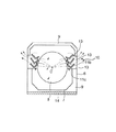
図2に示すように、リブ11は、ランプ中央位置Cから開口10に至る放射状の仮想直線(図中一点鎖線:ランプ破裂の際の破片飛翔軌跡を想定)上に突出する形状で設けられる。すなわち、放射線がリブ11に触れずに開口10から外部に通り抜けるのを遮るようにリブ11の配置位置および形状を設定している。このランプ中央位置Cは、ランプ3の破裂部分を中心点に想定したものである。これにより、破裂片が開口10を通じて外に飛び出ることがない。
【0033】
リブ11の形状は、破裂片が当たった場合に、この破裂片を下方に落とすような角度を有するようにするのが好ましい。例えば、リブ11はV形状をしており、このランプ3側の斜面11aは下方に傾斜しており、破裂片が当たった場合にこの破裂片を下方に落とすように作用する。開口10側の斜面11bは、同じく下方に傾斜し、リブ11とリブ11の間のノズル13を通じて熱気がリブ11の面を伝わり、開口10から放出される。
【0034】
リブ11を設ける個数は、例えば、同図に示す例では3個形成したが、これに限らない。また、各リブ11の端部11cは、リフレクタ4のフランジ部5に当接してこのリフレクタ4を位置決めする。すなわち、このリブ11の端部11cは、上記の当接面7と同様に機能する。
【0035】
なお、リブ11は、ランプホルダ1と一体成形するのが製造上好ましいが、別部品として成形し、ランプホルダ1の所定位置にそれぞれ固着するようにしてもよい。また、リブ11を含むランプホルダ1は耐熱性樹脂からなり、例えばポリフェニレンサルファイド(PPS)、ポリエーテルエーテルケトン(PEEK)、結晶性ポリマー(LCP)などの樹脂からなる。この他、耐熱性(100〜150℃程度)を有するフッ素繊維、ナイロン、ポリエステル等でもよい。
【0036】
リブ11の第2の機能は、区画室12を介してリフレクタ4内部の熱を効果的に外部に放出させることである。開口10の形成により内部の熱を放出できるが、開口10に従来のようにメッシュ材を張ると、実質的に開口率が低下して空気の流動性が悪くなる。特に、ランプ3の破裂片のように小さいものを補足するには、細かい目のメッシュ材が必要となるため、空気の流動性は明らかに低下する。これに対して、この発明のリブ11によれば、これらにより加熱空気が流れるノズル13が形成され、このノズル13はわずかに折れ曲がった極めて単純な形状であるから、開口率の低下が殆どなく、リフレクタ4内部の熱を効果的に外に放出することができる。熱の流れを図中点線で示した。なお、前記ノズル13とは、リブ11とリブ11との間に形成された空気の流路であり、リブ11と周壁9との間に形成されるものも含まれる。
【0037】
リブ11の形状は、熱の流れを阻害しないように考慮する。例えばランプ3の破裂片を確実に捕捉するために、リブ11を交互に配置してジグザグの迷路状のノズルを形成すると、破裂片の捕捉には効果的であるが、ノズル形状がシンプルでなくなり熱気の流動性が悪くなる。実施の形態1では、V形状のリブ11を連設して略V字形状に折れ曲がったノズル13を形成し、ノズル13の入り口をランプ3側に向け、出口を開口10側に向ける比較的シンプルな構成にしてある。
【0038】
開口10にメッシュ材などを取り付けないこと、ノズル13の形状がシンプルなことから、外からこの開口10を通じて区画室12内に冷風を導入することができる。このため、ホルダ周囲の空気の流れにより、リフレクタ4内部を積極的に冷却することができる。その際は、冷風を導入した側の開口10とは反対の開口10から熱気が放出されることになる。このような点からも、周壁9の両側面に開口10を設けることが好ましい。これに対して、従来のようにメッシュ材を開口10に設けた場合は、外から区画室12内に冷風を送り込むことが難しくなるため、リフレクタ4およびランプ3を十分に冷却できない。なお、リブ11をランプホルダ1に一体成形することで製造工程を簡略化してコスト低減できるという効果もある。
【0039】
ランプホルダ1のフロント部6は、映像投射装置の筐体底面に固定する構成とするほか、図3に示すように、光源装置100の交換を容易化するためにフロント部6を底面板14にネジ等で固定したり、フロント部6と底面板14を一体形成してもよい。底面板14とフロント部6が一体化されることにより、光源装置100をユニット化することができ、ランプ3の破損時における交換をより容易化できるようになる。この場合、底面板14には、光源装置100の挿抜操作を行う際に指を引っかけて、光源装置100を取り外し方向に(例えば図3中矢印方向)引き出すための操作アーム15を設けてもよい。
【0040】
以上説明した実施の形態1によれば、ランプ使用中にランプ3が破裂した場合でも、その破裂片が光源装置100の開口10から外に飛び出ることがなく、かつ、この開口10からリフレクタ4内部の熱を効率的に排出できる。また、製造工程を簡略化できかつコストも低減できる。リフレクタ4に切り欠きや封鎖板を設ける構成ではないので、反射率の低下をもたらすこともなく、十分な光量を得ることができる。
【0041】
なお、上記実施の形態1では、この発明のリブ11として比較的薄肉のものを図示したが、これより肉厚のものとしてもよい。また、多数の柱状突起を直線的または曲線的に連設して擬似的にリブ状にしたものとしてもよい。さらに、実施の形態1では、リブ11をフロント部6に設けたが、リフレクタ4のフランジ部5側に設けてもよい。
【0042】
(実施の形態2)
図4は、この発明の実施の形態2にかかるランプホルダを示す図である。図4(a)は、ランプホルダ正面図、図4(b)は、同側面図である。なお、ランプ3およびリフレクタ4の構成は図1および図3と同様であり、説明を省略した。このランプホルダ201のフロント部206には、ランプユニット2の前端のフランジ部5が接触する当接面207が設けられ、その周囲には周壁209が形成される。周壁209の側面中央には、放熱用の開口210が形成されている。この開口210付近には、ランプ3の破裂片を受ける機能と効率的に放熱を行う機能を備えたリブ211が形成されている。具体的には、このリブ211は、略π形状に形成され、ランプ3の中央位置Cから開口210までの放射線上(径方向)に壁部211aを形成し、かつその足部211b,211cは開口210から突出してそれぞれ上下方向に折れ曲がっている。リブ211は、ランプホルダ201と一体成形してもよいし、別部品として取り付けてもよい。このリブ211の端部211dは、ランプユニット2のフランジ部5と当接して当接面となる。
【0043】
ランプ3が破裂した場合、その破裂片は放射状に飛び散るが、リブ211の壁部211aがランプ中央位置Cからの放射線上に位置しているから、この破裂片が開口210から飛び出ることはない。また、リブ211の上側の足部211bは、壁部211aに衝突せず周壁209に当たり落下した破裂片を受け止め、これらが開口210から外に出るのを防止する。このようなリブ構造によれば、ランプ3の破裂片が開口210から外に飛び出るのを防止できる。また、区画室212とリフレクタ4内部の熱気は、リブ211と周壁209により形成されたノズル213を通じて外に放出される(熱気の流れを点線矢印で示す)。
【0044】
このとき、このリブ211が形成するノズル形状は、比較的単純な形状となるから、内部の熱気は放出されやすい。熱気はリブ211の上方の足部211bに案内され、上方に放出される。各リブ211の足部211b,211cが上方向および下方向に折れ曲がるように形成されているのは、光源装置を上下逆に設置した場合(光源装置を内蔵した映像投射装置を天吊りで上下逆に設置した場合)に、同様の効果を得るためである。すなわち、仮に上下が逆になっても、かかる足部211b,211cは同様の状態を保つので、前記同様に区画室212とリフレクタ4の熱気は前記ノズル213を通じて外に放出される。
【0045】
また、ランプホルダ201の外側の対流により、リブ211近傍に上昇気流が存在すれば、リブ211のノズル213から出た熱気もその対流に沿って上昇して循環する。特に、このリブ211は、足部211b,211cがランプホルダ201から突出していることで、放熱フィンとして機能する。すなわち、区画室212とリフレクタ4内部のランプ3の熱がリブ211の壁部211aから足部211b,211cに伝わり、外に突出した部分で外気に触れて熱交換される。このため、ランプホルダ201の内部のみにリブ211を設ける場合に比べて、放熱効果を高めることができる。特に、リブ211を熱伝導性のよい材料、例えばアルミニウム、銅等で別体製作し、ランプホルダ201に固着するようにすれば、より放熱効果がある。また、樹脂製のリブ211の周囲に金属膜を取り付けてもよい。
【0046】
なお、樹脂製の場合でも、MIM成形の場合のようにこの樹脂にアルミニウム等の金属粉末を混合させたものを用い、ランプホルダ201自体を射出成形すれば、同様の効果がある。その場合は、ランプホルダ201全体としての熱伝導性が高まり、外気との熱交換を容易に行うことができる。また、リブ211のうち、下方に位置するリブ211の足部211cは、上昇気流があればこの足部211cに案内されて外部の空気が内部に導かれる。これにより、区画室212を介してリフレクタ4内部に冷却空気が送り込まれて、冷却効果が高まる。
【0047】
以上実施の形態2のランプホルダによれば、ランプ3の破裂片が開口210から外に飛び出るのを防止でき、かつリフレクタ4内部の熱を効果的に外に放出できる。さらに、熱交換率が高まり、放熱性が極めてよくなる。なお、上記同様、リブ211を一体成形することで製造工程が簡略化され、コスト低減化が図れるようになる。
【0048】
(実施の形態3)
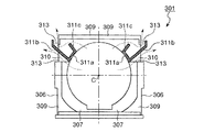
図5は、この発明の実施の形態3にかかるランプホルダを示す正面図である。このランプホルダ301は、上記実施の形態1に示すランプホルダと略同様の構成であるが、リブ311のみ形状が異なる。このランプホルダ301の開口310は、周壁309の上方に位置する。周壁309の内側には、ランプユニットのフランジ部が当接する当接面307が形成される。また、ランプホルダ301のフロント部306の上方でかつ開口310近傍には、リブ311が設けられている。このリブ311は略J形状であり、長足311bの端部は、前記開口310から突出してその端部が上方に折れ曲がっている。短足311cは、ホルダ内に位置している。壁部311aは、ランプ中央位置Cからの放射線が開口310を直接通過しないよう、この放射線に交差するように配置形成されている。
【0049】
このような実施の形態3のランプホルダ301によれば、ランプの破裂片は、壁部311aに当たって前記開口310から外部に飛び出ることはなく、かつリフレクタ内部の熱気は、リブ311により形成したノズル313を通して外部に放出される(熱気の流れを点線で示す)。このとき、外部に空気の上昇気流が存在すれば、リブ311の長足311bから出た熱気は対流に乗って外部に流れ出るようになる。また、長足311bが外部に突出することで上記実施の形態2で説明したような放熱フィンとしての機能が得られる。以上から、このランプホルダ301においても、ランプの破裂片が飛び散るのを防止し、かつリフレクタ内部の熱気を効果的に外部に放出できる。さらに、リブ311を一体成形することで製造コストを低減できる。
【0050】
(実施の形態4)
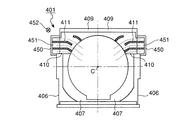
図6は、この発明の実施の形態4にかかるランプホルダを示す正面図である。このランプホルダ401は、上記実施の形態1に示すランプホルダと略同様の構成であるが、リブ411の形状のみ異なる。このランプホルダ401の開口410は、周壁409の上方に位置する。リブ411は、ランプ側端部が折れ曲がった形状であり、他端が開口410から突出した形状である。また、開口410には、図の垂直方向(手前側)に開端を有するカバー450が設けられている。カバー450により開口410の外側に排気通路451が形成される。周囲の気流の流れ方向(空気の流れ方向452)が図の垂直方向(ランプホルダ401の前面から背面、すなわち、図の奥から手前側)である場合、一方の開口410から排気通路451内に空気が導入され、他方の開口410からリフレクタ内部の熱気が放出されるようになる。また、リブ411は、排気通路451内にその端部が位置しているから、外気の流れにさらされて放熱フィンとして機能する。なお、不図示であるが、光源装置の後方にファンを設置して、積極的に熱気を吸引するようにしてもよい。
【0051】
また、これに限らず、一方のカバー450の開口方向をランプホルダ401の前面側とし、他方のカバー450の開口方向をランプホルダ401の背面側としてもよい。この場合、一方のカバー450から外気を取り込み、他方のカバー450側からリフレクタ内部の熱気を放出できるようになる。
【0052】
ランプの破裂片は、リブ端部の折れ曲がった部分に当たり、開口410には殆ど至らない。開口410に破裂片が届いてもカバー450の内壁に当たり、それ以上外に飛び出ることはない。なお、このリブ411および排気通路451は、ランプホルダ401と一体成形してもよいし、別体として組み立ててもよい。なお、リブ411とフロント部406とからなる当接面407に、ランプユニットのフランジ部が位置決めされ当接される。このように、かかる構成の場合にも、ランプの破裂片が飛び散るのを防止し、かつ内部の熱気を効果的に外部に放出できる。さらに、リブ411を一体成形することで製造コストを低減できる。
【0053】
(実施の形態5)
この発明のランプホルダは、上記実施の形態1〜4に示すような構成のほか、以下のような構成を採用できる。図7は、そのような変形例を示す説明図である。図7(a)に示すランプホルダは、湾曲形状のリブ511をランプホルダのフロント部6に形成した構造である。その他の構成は上記実施の形態1に示した光源装置と同様であり説明を省略する。具体的には、上下に湾曲したリブ511a,511bを形成し、これらにより湾曲形状のノズル513を形成する。ランプホルダの周壁9の中央付近には、リフレクタ内部の熱を放出する開口10が設けられている。前記上下のリブ511は、ランプ中央位置Cから開口10に至る放射線上に突出して遮るように設けられている。なお、上側のリブ511bは、空気が通りやすいように2分割されている。また、図示は省略するが、この開口10およびリブ511は、ホルダ中心から対称の位置にも形成されている。
【0054】
リブ511はランプホルダ1と一体成形してもよいし、別部品として取り付けてもよい。また、リブ端部がランプユニットのフランジ部の当接面となるのは、上記実施の形態と同様である(下記図7(b)〜図7(d)において同じ)。かかる構成において、ランプの破裂片は、ランプ中央位置Cから放射線上に設けてある上下のリブ511に衝突して落下する。また、ランプに起因するリフレクタ内の熱気は、リブ511により構成したノズル513に従って開口10から外部に放出される。このノズル513は比較的シンプルな構成であるため、上記実施の形態の光源装置と同様に熱気が内部にこもることなく、効果的に外に放出できる。このため、リフレクタ内部の冷却効果が高まる。
【0055】
図7(b)に示す構成は、ランプホルダのフロント部6に2つの円弧状のリブ521aと、三角形のリブ521bと、上方に設けた径方向のリブ521cとを設けた構成である。ランプホルダの周壁9の中央付近には、リフレクタ内部の熱を放出する開口10が設けられている。円弧状のリブ521aは、ランプ中央位置Cから開口10に至る放射線上に突出し遮るように設けられている。三角形のリブ521bは、円弧状のリブ521aの隙間であってランプ中央位置Cから開口10への放射線上にある。このリブ521によれば、ランプの破裂片は円弧状のリブ521aによりその飛散を防止され、この円弧状のリブ521aの間を抜けた破裂片は三角形のリブ521bに衝突して下方に落とされる。上方の径方向のリブ521cは周壁9に当たって落下した破裂片が外に出ないようにする。ランプにより加熱された内部の熱気は、リブ521により形成されたノズル522を通じて外部に放出される。この図7(b)に示す例でも、簡単なノズル形状であるから、リフレクタ内部の空気が放出されやすく、外部から冷却風を入れやすい。
【0056】
図7(c)に示す構成は、円弧状の内側と外側のリブ531a,531bと、上方に位置する径方向のリブ531cとからなる。内側のリブ531aと外側のリブ531bとは、ランプ中央位置Cからの放射方向で互いの端部が重なっている。このため、ランプの破裂片は、この円弧状のリブ531a,531bに衝突して下方に落下させられる。径方向のリブ531cは、フロント部6の周壁9に衝突して落下する破裂片が開口10から外に出るのを防止する。リフレクタ内部の熱気は、これらのリブ531により比較的簡単に構成されたノズル532を通って開口10から放出される。
【0057】
図7(d)に示す構成では、実施の形態1に示したようなリブ541の端部を延長して、開口10から突出させている。リフレクタ内部の熱気は、リブ541により形成したノズル542により外に放出される。このリブ541の作用は、上記実施の形態1で説明した通りであるが、さらにリブ541を開口10から突出させたことで、このリブ541が放熱フィンとして機能し、内部熱がリブ541を介して外部に伝えられる。フロント部6の外側にファンなどによる空気の流れがあれば、より熱交換がされやすくなる。さらに放熱効果を高めるには、前記リブ541をアルミニウムや銅等の熱伝導性のよい材料で製作してもよいし、樹脂製のリブ541の表面にアルミニウムや銅等の金属膜を設けるようにしてもよい。
【0058】
(実施の形態6)
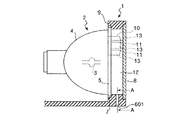
図8は、実施の形態6にかかるランプホルダを示す斜視図である。図9は、図8の断面図である。このランプホルダ1は、実施の形態1に示したランプホルダ100と略同様の構成であるが、フロント部6の周壁9の下方に第2の開口601を設けた点が異なる。その他の構成は説明を省略し、同一構成要素には同一の符号を付してある。周壁9の下方に設けた開口601は、区画室12内と外部とを連通しており、ランプホルダ1の下面に向いて開いている。
【0059】
この実施の形態6の光源装置600では、第2の開口601から区画室12を介してリフレクタ4内部に冷気を導入し、内部の熱気を周壁9側方の開口10から外部に放出させる。これにより、ランプ3の冷却をより効率的に行うことができる。なお、空気の流れは、図8中において点線矢印で示す。また、第2の開口601の形状や大きさは、必要とする冷却能力に従い適宜決定すればよい。図には、円形断面の開口601を例示したが、断面が矩形の開口であってもよい。さらに、図示しないが、第2の開口601から区画室12を介してリフレクタ4内部にファン(不図示)からダクトを介して導出した空気流を積極的に導入するようにしてもよい。また、この第2の開口601を、光源装置600を設置した機器内の空気の流れに向くようにし、区画室12を介してリフレクタ4内部に空気を導入しやすくするようにしてもよい。
【0060】
また、第2の開口601が図8に示したような直線的な形状の場合、ランプの破裂片がこの開口から外部に飛び出る可能性があるため、第2の開口601の形状にトラップ部(溜め部)を設けるようにしてもよい。図10は、図9のA−A断面図である。図10(a)に示すように、開口602は、折れ曲がった形状であって経路途中の折れ曲がった部分に溜り部603を有するものとしてもよい。この形状の開口602では、区画室12内から侵入した破裂片は、開口602内の溜り部603で溜められる。一方、外部からの空気は、開口形状が比較的簡単であるため、区画室12内に侵入しやすい。
【0061】
また、図10(b)に示すように、階段状にしてもよい。かかる形状の開口604では、区画室12から侵入した破裂片は途中の段部605にて溜められ、その一方で外部からの空気は開口形状が比較的簡単であることから、区画室12内に入りやすい。この他、開口の形状は、ランプの破裂片が外部に飛び出ないような形状であり、かつ、区画室12を介してリフレクタ4内部に空気を効率的に導入できる形状であればよい。
【0062】
以上説明した各実施の形態に示したランプホルダは、プロジェクタ等の映像投射装置、車両のヘッドライト、スポットライト等に用いる光源装置の発光面前面に設けて好適である。以上、本発明の一実施形態を図面に沿って説明した。しかしながら本発明はこの実施の形態に示した事項に限定されず、特許請求の範囲の記載に基づいてその変更、改良等が可能である。
【0063】
【発明の効果】
以上説明したように、この発明によれば、開口に設けたリブにより、ランプが破裂した場合の破裂片が外に飛び出るのを防止するとともに、リフレクタ内部の熱気を効率的に放出させランプの冷却が行えるという効果を奏する。
【図面の簡単な説明】
【図1】この発明の実施の形態1にかかるランプホルダを示す組立図である。
【図2】図1に示したランプホルダの正面図である。
【図3】図1に示したランプホルダの断面図である。
【図4】この発明の実施の形態2にかかるランプホルダを示す図である。
【図5】この発明の実施の形態3にかかるランプホルダを示す正面図である。
【図6】この発明の実施の形態4にかかるランプホルダを示す正面図である。
【図7】この発明の実施の形態5にかかるランプホルダの各種変形例を示す説明図である。
【図8】この発明の実施の形態6にかかるランプホルダを示す斜視図である。
【図9】図8に示したランプホルダの断面図である。
【図10】図9のA−A断面図である。
【図11】従来のランプホルダの一例を示す斜視図である。
【符号の説明】
1 ランプホルダ
2 ランプユニット
3 ランプ
4 リフレクタ
6 フロント部
8 透光ガラス
9 周壁
10 開口
11 リブ
12 区画室
13 ノズル
100 光源装置[0001]
TECHNICAL FIELD OF THE INVENTION
The present invention relates to a lamp holder provided on an image projection device or the like and provided on the front surface of a reflector of a lamp such as a metal halide lamp, and more particularly, to prevent scattering of debris when the lamp is damaged, and efficiently reduce heat inside the reflector. The present invention relates to a lamp holder capable of dissipating heat.
[0002]
[Prior art]
FIG. 11 is a perspective view showing an example of a conventional lamp holder (see
[0003]
The
[0004]
[Patent Document 1]
JP-A-10-254061
[0005]
[Problems to be solved by the invention]
In the above-described conventional
[0006]
SUMMARY OF THE INVENTION An object of the present invention is to provide a lamp holder capable of preventing a ruptured piece from jumping out at the time of lamp rupture and efficiently discharging hot air inside the lamp in order to solve the above-mentioned problems caused by the conventional technology. .
[0007]
[Means for Solving the Problems]
In order to achieve the above object, a lamp holder according to the invention of
[0008]
According to the first aspect of the invention, when the lamp of the lamp unit ruptures, the ruptured pieces scatter radially around the lamp. Since the rib that blocks the radial virtual straight line is formed, it is possible to prevent the scattered rupture pieces from colliding with the rib and jumping out of the opening. Further, even if the temperature inside the reflector rises due to the heat of the lamp, the hot air inside the reflector is efficiently released to the outside through the ribs through the ribs, and the inside of the lamp and the reflector can be effectively cooled.
[0009]
A lamp holder according to a second aspect of the present invention is a lamp holder attached to a front surface of a lamp unit including a lamp and a reflector for condensing light from the lamp, the lamp holder being provided on the front surface of the lamp holder, And a light-transmitting plate for preventing the fragments when the lamp is broken from scattering to the outside, an opening provided on a side surface of the lamp holder, and a light-transmitting plate disposed at the opening portion. A rib configured to prevent the lamp from being exposed to the outside and to form a flow of air between the inside and the outside of the reflector.
[0010]
According to the second aspect of the invention, when the lamp of the lamp unit ruptures, the ruptured pieces scatter radially around the lamp. Since the opening is formed with a rib that does not allow the internal lamp to be exposed to the outside, the scattered ruptured pieces are prevented from colliding with the rib and jumping out of the opening. Further, even if the temperature inside the reflector rises due to the heat of the lamp, the hot air inside the reflector is efficiently released to the outside through the ribs through the ribs, and the inside of the lamp and the reflector can be effectively cooled.
[0011]
According to a third aspect of the present invention, in the lamp holder according to the first or second aspect, the rib is provided inside the opening, and one or a plurality of the ribs are provided to be bent. And
[0012]
According to the third aspect of the present invention, since the rib is provided inside the opening, there is no unnecessary projection outside, and the handling can be facilitated.
[0013]
A lamp holder according to a fourth aspect of the present invention is the lamp holder according to any one of the first to third aspects, wherein a part of the rib projects outside from the opening.
[0014]
According to the fourth aspect of the invention, since the rib projects from the opening, the hot air in the reflector can be reliably discharged to the outside. Further, depending on the material of the rib, since the rib itself functions as a radiation fin by protruding outside from the opening, the cooling effect inside the reflector can be further enhanced.
[0015]
According to a fifth aspect of the present invention, in the lamp holder according to the fourth aspect, the plurality of ribs protrude from the opening, and one end of one of the plurality of ribs is bent upward. It is characterized in that it is bent and the other end of the rib is bent downward.
[0016]
According to the fifth aspect of the invention, since each rib protruding from the opening is bent upward or downward, the same configuration can be maintained even when the light source device is installed upside down. Accordingly, when the opening is provided only on one side, for example, only on the upper side, if the opening is installed upside down, it is possible to prevent the opening from being located below and making it difficult to discharge the hot air in the reflector.
[0017]
According to a sixth aspect of the present invention, in the lamp holder according to any one of the first to fifth aspects, the openings are respectively provided on both side portions of the lamp holder, and the respective openings are provided on the outside. Characterized by being directed in the direction of air flow.
[0018]
According to the invention of
[0019]
According to a seventh aspect of the present invention, in the lamp holder according to any one of the first to fifth aspects, the openings are respectively provided on both side portions of the lamp holder, and the openings are provided with external parts. A cover having an open end opened on the downstream side in the air flow direction.
[0020]
According to the invention of
[0021]
Further, in the lamp holder according to the invention of
[0022]
According to the eighth aspect of the present invention, the cooling air can be positively introduced from one opening by the flow of air, and the hot air in the reflector can be discharged from the other opening. Can be more cooled.
[0023]
According to a ninth aspect of the present invention, in the lamp holder according to any one of the first to fifth aspects, a second opening is provided below the lamp holder, the second opening being directed to a flow direction of external air. It is characterized by having.
[0024]
According to the ninth aspect of the present invention, by providing the second opening below the peripheral wall, air can be introduced into the interior of the reflector from the opening. Thereby, while the cool air is introduced from the second opening, the hot air in the reflector can be discharged to the outside from the openings on both sides, so that the heat radiation efficiency can be further improved. An air flow such as a fan may be forcibly supplied from the second opening.
[0025]
BEST MODE FOR CARRYING OUT THE INVENTION
Hereinafter, preferred embodiments of a lamp holder according to the present invention will be described in detail with reference to the accompanying drawings. The lamp holder of the present invention has a function of dissipating heat inside the lamp unit while preventing the fragments from being scattered when the lamp is broken, being attached to the front surface of the lamp unit. A lamp unit to which a lamp holder is attached is used as a light source device of a video projector such as a projector.
[0026]
(Embodiment 1)
FIG. 1 is an assembly diagram showing a lamp holder according to the first embodiment of the present invention. FIG. 2 is a front view of the lamp holder shown in FIG. FIG. 3 is a sectional view of the lamp holder shown in FIG. The
[0027]
The
[0028]
A
[0029]
The
[0030]
As described above, since the
[0031]
Further, a
[0032]
As shown in FIG. 2, the
[0033]
It is preferable that the shape of the
[0034]
The number of the
[0035]
The
[0036]
The second function of the
[0037]
The shape of the
[0038]
Since no mesh material is attached to the
[0039]
The
[0040]
According to the first embodiment described above, even if the
[0041]
In the first embodiment, the
[0042]
(Embodiment 2)
FIG. 4 is a diagram illustrating a lamp holder according to a second embodiment of the present invention. FIG. 4A is a front view of the lamp holder, and FIG. 4B is a side view of the same. Note that the configurations of the
[0043]
When the
[0044]
At this time, the nozzle 211 formed by the rib 211 has a relatively simple shape, so that the internal hot air is easily released. The hot air is guided to the
[0045]
Also, if there is an upward airflow near the rib 211 due to convection outside the
[0046]
Even in the case of resin, similar effects can be obtained if the
[0047]
According to the lamp holder of the second embodiment, the ruptured pieces of the
[0048]
(Embodiment 3)
FIG. 5 is a front view showing the lamp holder according to the third embodiment of the present invention. This
[0049]
According to the
[0050]
(Embodiment 4)
FIG. 6 is a front view showing the lamp holder according to the fourth embodiment of the present invention. The
[0051]
Alternatively, the opening direction of one
[0052]
The rupture of the lamp hits the bent portion of the end of the rib and hardly reaches the
[0053]
(Embodiment 5)
The lamp holder of the present invention can adopt the following configuration in addition to the configuration as shown in the first to fourth embodiments. FIG. 7 is an explanatory diagram showing such a modification. The lamp holder shown in FIG. 7A has a structure in which a curved rib 511 is formed on the
[0054]
The rib 511 may be formed integrally with the
[0055]
The configuration shown in FIG. 7B is a configuration in which two arc-shaped ribs 521a, a
[0056]
The configuration shown in FIG. 7C includes arcuate inner and
[0057]
In the configuration shown in FIG. 7D, the end of the
[0058]
(Embodiment 6)
FIG. 8 is a perspective view showing a lamp holder according to the sixth embodiment. FIG. 9 is a sectional view of FIG. The
[0059]
In the
[0060]
Further, when the
[0061]
Further, as shown in FIG. 10B, the shape may be stepwise. In the
[0062]
The lamp holders described in the embodiments described above are preferably provided on the front surface of the light emitting surface of a light source device used for a video projector such as a projector, a headlight of a vehicle, a spotlight, or the like. The embodiment of the present invention has been described with reference to the drawings. However, the present invention is not limited to the matters described in this embodiment, and modifications, improvements, and the like can be made based on the description in the claims.
[0063]
【The invention's effect】
As described above, according to the present invention, the rib provided in the opening prevents the ruptured piece from jumping out when the lamp ruptures, and efficiently discharges the hot air inside the reflector to cool the lamp. The effect that it can perform is produced.
[Brief description of the drawings]
FIG. 1 is an assembly diagram showing a lamp holder according to a first embodiment of the present invention.
FIG. 2 is a front view of the lamp holder shown in FIG.
FIG. 3 is a sectional view of the lamp holder shown in FIG. 1;
FIG. 4 is a diagram illustrating a lamp holder according to a second embodiment of the present invention;
FIG. 5 is a front view showing a lamp holder according to a third embodiment of the present invention.
FIG. 6 is a front view showing a lamp holder according to a fourth embodiment of the present invention.
FIG. 7 is an explanatory view showing various modifications of the lamp holder according to the fifth embodiment of the present invention;
FIG. 8 is a perspective view showing a lamp holder according to a sixth embodiment of the present invention.
FIG. 9 is a sectional view of the lamp holder shown in FIG. 8;
FIG. 10 is a sectional view taken along line AA of FIG. 9;
FIG. 11 is a perspective view showing an example of a conventional lamp holder.
[Explanation of symbols]
1 Lamp holder
2 Lamp unit
3 lamps
4 Reflector
6 Front part
8 Translucent glass
9 Perimeter wall
10 opening
11 ribs
12 compartments
13 nozzle
100 light source device
Claims (9)
前記ランプホルダの前面に設けられ、前記ランプの光を外部に出射させるとともに、前記ランプ破損時の破片が外部に飛散することを防止するための透光板と、
前記ランプホルダの側面に設けられる開口と、
前記開口部分に配置され、前記ランプの中心から前記開口を通過して外部に至る放射状の仮想直線を遮り、かつ前記リフレクタ内部と外部の間で空気の流れを形成させる形状のリブと、
を備えたことを特徴とするランプホルダ。A lamp holder attached to a front surface of a reflector that houses the lamp and collects light from the lamp,
A light-transmitting plate that is provided on a front surface of the lamp holder and emits the light of the lamp to the outside, and that prevents fragments at the time of lamp damage from being scattered outside;
An opening provided on a side surface of the lamp holder;
A rib arranged at the opening portion, blocking a radial virtual straight line from the center of the lamp through the opening to the outside, and forming a flow of air between the inside and outside of the reflector;
A lamp holder comprising:
前記ランプホルダの前面に設けられ、前記ランプの光を外部に出射させるとともに、前記ランプ破損時の破片が外部に飛散することを防止するための透光板と、
前記ランプホルダの側面に設けられる開口と、
前記開口部分に配置され、該開口から前記ランプを外部に露見させず、かつ前記リフレクタ内部と外部の間で空気の流れを形成させる形状のリブと、
を備えたことを特徴とするランプホルダ。In a lamp holder attached to the front of a lamp unit including a lamp and a reflector that collects light from the lamp,
A light-transmitting plate that is provided on a front surface of the lamp holder and emits the light of the lamp to the outside, and that prevents fragments at the time of lamp damage from being scattered outside;
An opening provided on a side surface of the lamp holder;
A rib disposed in the opening portion, wherein the rib does not expose the lamp to the outside from the opening and forms a flow of air between the inside and outside of the reflector;
A lamp holder comprising:
Priority Applications (1)
| Application Number | Priority Date | Filing Date | Title |
|---|---|---|---|
| JP2003026289A JP2004239975A (en) | 2003-02-03 | 2003-02-03 | Lamp holder |
Applications Claiming Priority (1)
| Application Number | Priority Date | Filing Date | Title |
|---|---|---|---|
| JP2003026289A JP2004239975A (en) | 2003-02-03 | 2003-02-03 | Lamp holder |
Publications (2)
| Publication Number | Publication Date |
|---|---|
| JP2004239975A true JP2004239975A (en) | 2004-08-26 |
| JP2004239975A5 JP2004239975A5 (en) | 2006-01-05 |
Family
ID=32954344
Family Applications (1)
| Application Number | Title | Priority Date | Filing Date |
|---|---|---|---|
| JP2003026289A Pending JP2004239975A (en) | 2003-02-03 | 2003-02-03 | Lamp holder |
Country Status (1)
| Country | Link |
|---|---|
| JP (1) | JP2004239975A (en) |
Cited By (8)
| Publication number | Priority date | Publication date | Assignee | Title |
|---|---|---|---|---|
| EP1838098A1 (en) * | 2006-03-15 | 2007-09-26 | Funai Electric Co., Ltd. | Projection apparatus |
| JP2008076661A (en) * | 2006-09-20 | 2008-04-03 | Sony Corp | Sealed lamp device and projector |
| JP2008310132A (en) * | 2007-06-15 | 2008-12-25 | Hitachi Ltd | Projector device |
| US7472996B2 (en) | 2006-04-06 | 2009-01-06 | Funai Electric Co., Ltd. | Projector having first and second ventilation openings and first and second barrier members |
| JP2009031609A (en) * | 2007-07-27 | 2009-02-12 | Canon Inc | Image projection device |
| JP2009181966A (en) * | 2007-03-06 | 2009-08-13 | Seiko Epson Corp | Light source device and projector |
| US7972013B2 (en) | 2007-03-06 | 2011-07-05 | Seiko Epson Corporation | Light source having a holding unit with air supply port for cooling air and projector |
| JP2015108657A (en) * | 2013-12-03 | 2015-06-11 | 株式会社リコー | Image projection device and discharge lamp |
-
2003
- 2003-02-03 JP JP2003026289A patent/JP2004239975A/en active Pending
Cited By (9)
| Publication number | Priority date | Publication date | Assignee | Title |
|---|---|---|---|---|
| EP1838098A1 (en) * | 2006-03-15 | 2007-09-26 | Funai Electric Co., Ltd. | Projection apparatus |
| US7819535B2 (en) | 2006-03-15 | 2010-10-26 | Funai Electric Co., Ltd. | Projection apparatus and cover glass attaching structure |
| US7472996B2 (en) | 2006-04-06 | 2009-01-06 | Funai Electric Co., Ltd. | Projector having first and second ventilation openings and first and second barrier members |
| JP2008076661A (en) * | 2006-09-20 | 2008-04-03 | Sony Corp | Sealed lamp device and projector |
| JP2009181966A (en) * | 2007-03-06 | 2009-08-13 | Seiko Epson Corp | Light source device and projector |
| US7972013B2 (en) | 2007-03-06 | 2011-07-05 | Seiko Epson Corporation | Light source having a holding unit with air supply port for cooling air and projector |
| JP2008310132A (en) * | 2007-06-15 | 2008-12-25 | Hitachi Ltd | Projector device |
| JP2009031609A (en) * | 2007-07-27 | 2009-02-12 | Canon Inc | Image projection device |
| JP2015108657A (en) * | 2013-12-03 | 2015-06-11 | 株式会社リコー | Image projection device and discharge lamp |
Similar Documents
| Publication | Publication Date | Title |
|---|---|---|
| JP4059251B2 (en) | Light source device and projector | |
| CN100369491C (en) | LCD Projectors and Lamps | |
| KR100196681B1 (en) | Optics and Cooling Methods | |
| US20060232973A1 (en) | Lamp cooling device and projection display apparatus | |
| US8322861B2 (en) | Lamp source module and projection system | |
| US6981782B2 (en) | Lamp with reflecting mirror and image projecting apparatus | |
| US7367679B2 (en) | Light source for a display device | |
| JP2011221482A (en) | Light source apparatus and projector | |
| JP2004239975A (en) | Lamp holder | |
| TWI235805B (en) | Light source and projector | |
| US20060050512A1 (en) | Ultra-high pressure discharge lamp unit and light source apparatus | |
| JP2009129590A (en) | Light source device | |
| JP4273912B2 (en) | Light source device | |
| JP2007279118A (en) | projector | |
| JP5246310B2 (en) | Strobe device | |
| JPH08314011A (en) | Liquid crystal projector light source device | |
| JP2010197583A (en) | Stroboscopic device | |
| JP4090272B2 (en) | Light source device | |
| JP2004219752A (en) | Video projection device and cooling method for video projection device | |
| JP2001125195A (en) | Light source device and display device using the same | |
| JP4872355B2 (en) | Strobe device | |
| JP2004095341A (en) | Light source unit cooling mechanism and projector using the same | |
| JP2011076071A (en) | Projection display | |
| JP2002365729A (en) | Lamp house for projector | |
| JPH11144521A (en) | Projector |
Legal Events
| Date | Code | Title | Description |
|---|---|---|---|
| A521 | Written amendment |
Free format text: JAPANESE INTERMEDIATE CODE: A523 Effective date: 20051107 |
|
| A621 | Written request for application examination |
Free format text: JAPANESE INTERMEDIATE CODE: A621 Effective date: 20051107 |
|
| A977 | Report on retrieval |
Free format text: JAPANESE INTERMEDIATE CODE: A971007 Effective date: 20081009 |
|
| A131 | Notification of reasons for refusal |
Free format text: JAPANESE INTERMEDIATE CODE: A131 Effective date: 20081014 |
|
| A02 | Decision of refusal |
Free format text: JAPANESE INTERMEDIATE CODE: A02 Effective date: 20090303 |