JP2004242527A - Scissors for high branch - Google Patents
Scissors for high branch Download PDFInfo
- Publication number
- JP2004242527A JP2004242527A JP2003033700A JP2003033700A JP2004242527A JP 2004242527 A JP2004242527 A JP 2004242527A JP 2003033700 A JP2003033700 A JP 2003033700A JP 2003033700 A JP2003033700 A JP 2003033700A JP 2004242527 A JP2004242527 A JP 2004242527A
- Authority
- JP
- Japan
- Prior art keywords
- branch
- fixed
- movable
- scissors
- blade
- Prior art date
- Legal status (The legal status is an assumption and is not a legal conclusion. Google has not performed a legal analysis and makes no representation as to the accuracy of the status listed.)
- Granted
Links
- 230000005540 biological transmission Effects 0.000 description 4
- 238000010008 shearing Methods 0.000 description 2
- 230000006835 compression Effects 0.000 description 1
- 238000007906 compression Methods 0.000 description 1
- 238000010586 diagram Methods 0.000 description 1
Images
Landscapes
- Scissors And Nippers (AREA)
Abstract
Description
【0001】
【産業上の利用分野】
本発明は、切断した枝を挟持する枝保持機構を備えた高枝鋏に関するものである。
【0002】
【従来の技術】
高枝鋏は、周知の通り伸縮棒体の先部に、枢結した固定刃と可動刃体で構成した鋏部を設け、基部に前記可動刃体と伝達杆を介して連結して鋏部を動作させる操作部を設けてなる。
【0003】
また前記高枝鋏には、切断した枝をそのまま保持する枝挟み機構を備えた器具も知られている(特許文献1、2)。
【0004】
特許文献1に開示されている高枝鋏は、可動刃体の側面に突出固定した基盤に、刃縁に隣接した枝挟み板の背面に設けた2本の支軸を出入自在に挿着し、基盤と枝挟み板との間に圧縮発条を改装し、固定刃に付設した固定枝受け部とで切断枝を挟圧保持するようにしているものである。
【0005】
また特許文献2に開示されている高枝鋏は、枝挟み部を、一端に案内部を有する板バネで形成し、前記板バネは、ほぼ鋏部の枢結軸上の位置で装着される一端から、一旦前方へ延設された後、刃縁先端付近で折り返されて再び後方へ延設され、他端が前記一端と重合状態にて案内部へ摺動可能に挿入されるごとく、ほぼ閉ループ状に湾曲形成してなり、固定枝受け部と前記枝挟み部で、切断枝を挟圧保持するようにしているものである。
【0006】
【特許文献1】
実開昭54−120452号公報。
【特許文献2】
特開平9−9782号公報。
【0007】
【発明が解決しようとする課題】
前記した従来の高枝鋏の枝挟み機構は、可動枝挟み部の枝挟み面が平行に移動(特許文献1)するか、先端側が開口する方向へ移動(特許文献2)する構成である。
【0008】
ところで細い枝の切断並びに枝保持についてはあまり問題は生じないが、太い枝を切断した場合には、枝挟み面が平行移動した場合には、切断枝と枝挟み面とが点接触であり、切断枝が他の枝に接触したり、風に煽られたりするなど、切断枝に不測の力が作用すると容易に枝の保持が解除されてしまう虞がある。また先端側が開口移動する枝挟みでは、切断枝を先端側で切断保持すると、剪断力及び保持力が弱いし、根元側ほど(枢結軸に近い方)剪断力並びに保持力が高まるが、根元側の枝挟み部は開口方向への移動が制限されるので、結果的に当該箇所での枝の切断可能太さに限界があり、太い枝は刃先側での切断保持となってしまう。
【0009】
そこで本発明は、枝が太くとも切断刃の根元側で枝切断並びに枝保持が可能な高枝鋏を提案したものである。
【0010】
【課題を解決する手段】
本発明に係る高枝鋏は、伸縮棒体の先部に、枢結した固定刃と可動刃体で構成した鋏部を設け、基部に前記可動刃体を動作させる操作部を設けた高枝鋏において、固定刃体の側面に固定刃体の受け湾曲形状の刃縁に添って固定枝受け部を設け、可動刃体側に前記固定枝受け部に対面して枝挟み面を備え、刃先部分で枢結して回動自在に可動刃体に装着した可動枝挟み部を設けると共に、枝挟み面が固定枝受け部から遠ざかる回動に対して抵抗付勢する発条を付設したことを特徴とするものである。
【0011】
従って枝を開口した刃体の間のできるだけ根元に差し入れ、操作部の動作で枝の切断を行うと共に、可動枝挟み部が回動することで、枝挟み部が切断の邪魔になることが無く、切断後は、固定枝受け部とで挟圧保持するものである。
【0012】
【実施の形態】
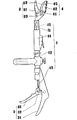
次に本発明の実施の形態について説明する。全体の基本的構成は、従前の高枝鋏と同様で、伸縮棒体1と、鋏部2と操作部3を備え、鋏部2に枝保持機構4を付設したものである。
【0013】
伸縮棒体1は内筒体11と外筒体12からなる二重筒体で、抜き差し自在にして伸縮可能とし、特に内部に伝達杆13を内装し、伝達杆13の伸縮並びに内外筒体11,12の伸縮固定操作を行う調整部14を備えてなる。また内筒体11の先端には、後述する鋏部2の固定刃体21を連結し先端側面に鋸装着部15を設けてなる。
【0014】
鋏部2は、固定刃体21と可動刃体22とを備え、固定刃体21は受け湾曲形状の刃を備え、その基部を内筒体11の先端に連結固定しており、可動刃体22は、半月状の刃で、固定刃体21に枢結(枢結軸23)すると共に、基端を伝達杆13と連結してなる。
【0015】
操作部3は、固定把手31と操作把手32とを備え、固定把手31は外筒体12の下端に連結固定し、操作把手32を固定把手31に枢結して回動自在とし、操作把手32の所定位置に伝達杆13を連結し、操作把手32の開閉操作で鋏部2の開閉操作を行うようにしてなる。また操作把手32を握持して鋏部2が閉じた状態を維持させるロック部33を設けてなる。
【0016】
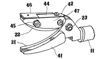
本発明の特徴である枝保持機構4は、固定枝受け部41と可動枝挟み部42とを備えたもので、固定枝受け部41は、固定刃体21の側面に固定刃体21の受け湾曲形状の刃縁に添って設けたもので、湾曲受け面は、刃縁に直交する細かい凹凸状に形成してなる。
【0017】
可動枝挟み部42は、鋏部2を全閉した状態で固定枝受け部41の湾曲受け面と対応する枝挟み面43を備え、枝挟み面43と反対側の峰面が可動刃体22の峰部とほぼ一致させた形状である。即ち可動刃体22の刃縁部分が可動枝挟み部42の枝挟み面43より突出してなるものである。
【0018】
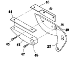
前記の可動枝挟み部42は、峰面に板バネ体44を添わせ、可動刃体22の先部において枢結(枢結軸45)し、可動刃体22の外側面に添わせると共に、板バネ体44の先方上面に庇状に突出させた支点部体46を、可動刃体22に固定してなる。
【0019】
また可動枝挟み部42の根元側(枢結軸23に近い方)に、枢結軸45と平行にガイド軸47をガイド長溝48に挿着して、可動刃体22側に突出させ、可動刃体22に、前記ガイド軸47が収まる枢結軸45を中心とする円弧状のガイド長溝49を設けてなる。
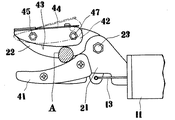
【0020】
而してロック部33を解除して、切断対象の枝Aを開口した刃体21,22の間のできるだけ根元側に差し入れ、操作部(固定把手31と操作把手32)の握持操作で鋏部2の開閉動作を行って、枝Aの切断をなす。前記の切断途中で枝Aは、固定枝受け部41と、可動枝挟み部42とで挟圧され、切断終了時には、可動枝挟み部42が回動し、支点部体46で一端が抑えられている板バネ体44が撓曲することで、挟圧力が生じ、切断後の枝Aをしっかりと保持するものである。尚可動枝挟み部42の可動範囲はガイド長溝48,49の長さの合算範囲である。
【0021】
【発明の効果】
以上のように本発明は、高枝鋏の鋏部に枝挟み機構を付設してなり、特に当該機構を、可動刃体側に固定枝受け部に対面して枝挟み面を備え、刃先部分で枢結して回動自在に可動刃体に装着した可動枝挟み部を設けると共に、枝挟み面が固定枝受け部から遠ざかる回動に対して抵抗付勢する発条を付設して構成したもので、枝が太くとも切断刃の根元側で枝切断並びに枝保持を可能として、効果的な切断枝保持を実現した高枝鋏を提供できたものである。
【図面の簡単な説明】
【図1】本発明の実施形態の全体図。
【図2】同要部斜視図。
【図3】同要部分解図。
【図4】同使用状態の説明図。
【符号の説明】
1 伸縮棒体
11 内筒体
12 外筒体
13 伝達杆
14 調整部
15 鋸装着部
2 鋏部
21 固定刃体
22 可動刃体
23 枢結軸
3 操作部
31 固定把手
32 操作把手
33 ロック部
4 枝保持機構
41 固定枝受け部
42 可動枝挟み部
43 枝挟み面
44 板バネ体
45 枢結軸
46 支点部体
47 ガイド軸
48,49 ガイド長溝[0001]
[Industrial applications]
The present invention relates to high branch scissors provided with a branch holding mechanism for holding a cut branch.
[0002]
[Prior art]
As is well known, the Takae scissors are provided with a scissor portion formed of a fixed blade and a movable blade that are pivotally connected at the tip of the telescopic bar, and the scissor portion is connected to the base via the movable blade and a transmission rod to form the scissors. An operation unit for operating is provided.
[0003]
Further, as the high branch scissors, there is also known a device provided with a branch pinching mechanism for holding a cut branch as it is (Patent Documents 1 and 2).
[0004]
The Takae scissors disclosed in Patent Document 1 inserts two support shafts provided on the back surface of a branch sandwiching plate adjacent to a blade edge into and out of a base protruding and fixed to a side surface of a movable blade body, The compression spring is modified between the base and the branch sandwiching plate, and the cutting branch is clamped and held by the fixed branch receiving portion attached to the fixed blade.
[0005]
Further, in the Takashige scissors disclosed in Patent Document 2, the branch pinching portion is formed by a leaf spring having a guide portion at one end, and the leaf spring is attached at a position substantially on a pivot shaft of the scissor portion. From the front edge, then folded back near the edge of the blade edge and extended rearward again, and the other end is slidably inserted into the guide portion in a state of being overlapped with the one end, so that a substantially closed loop is formed. The fixed branch receiving portion and the branch sandwiching portion hold the cutting branch by pressing.
[0006]
[Patent Document 1]
Japanese Utility Model Publication No. 54-120452.
[Patent Document 2]
JP-A-9-9782.
[0007]
[Problems to be solved by the invention]
The above-described conventional branch pinching mechanism of the high branch scissors has a configuration in which a branch pinching surface of a movable branch pinching portion moves in parallel (Patent Document 1) or moves in a direction in which the distal end side opens (Patent Document 2).
[0008]
By the way, cutting a thin branch and holding a branch does not cause much problem, but when a thick branch is cut, when the branch pinching surface moves in parallel, the cut branch and the branch pinching surface are in point contact with each other, When an unexpected force acts on the cutting branch, such as when the cutting branch comes into contact with another branch or is blown by the wind, the holding of the branch may be easily released. Further, in the branch pinch where the distal end side moves open, when the cutting branch is cut and held at the distal end side, the shearing force and the retaining force are weak, and the shearing force and the retaining force increase toward the root side (the one closer to the pivot axis). Since the movement of the side branch sandwiching portion in the opening direction is restricted, the cutable thickness of the branch at the position is limited, and the thick branch is cut and held on the cutting edge side.
[0009]
Therefore, the present invention proposes a high branch scissors capable of cutting and holding a branch at the base side of the cutting blade even if the branch is thick.
[0010]
[Means to solve the problem]
The scissors scissors according to the present invention is a scissors scissor comprising a scissor portion formed of a fixed blade and a movable blade connected at the tip of a telescopic rod, and an operating portion for operating the movable blade at a base portion. A fixed branch receiving portion is provided on a side surface of the fixed blade along the receiving blade edge of the fixed blade body, a movable blade body side is provided with a branch pinching surface facing the fixed branch receiving portion, and a pivotal edge is provided at a cutting edge portion. A movable branch clip portion rotatably attached to the movable blade body, and a ridge for biasing the branch clip surface against rotation away from the fixed branch receiving portion. It is.
[0011]
Therefore, the branch is inserted as much as possible between the opened blade bodies, the branch is cut by the operation of the operating unit, and the movable branch pinch is rotated, so that the branch pinch does not interfere with the cutting. After the cutting, the pressure is held by the fixed branch receiving portion.
[0012]
Embodiment
Next, an embodiment of the present invention will be described. The overall basic configuration is the same as that of the conventional Takae scissors, which comprises a telescopic rod 1, a scissor portion 2 and an operation portion 3, and a scissor portion 2 provided with a branch holding mechanism 4.
[0013]
The telescopic rod 1 is a double cylindrical body composed of an inner cylindrical body 11 and an outer
[0014]
The scissors portion 2 includes a
[0015]
The operation unit 3 includes a
[0016]
The branch holding mechanism 4, which is a feature of the present invention, includes a fixed
[0017]
The movable
[0018]
The movable
[0019]
Further, a
[0020]
Thus, the lock portion 33 is released, the branch A to be cut is inserted as close as possible between the opened
[0021]
【The invention's effect】
As described above, according to the present invention, the scissor portion of the high branch scissors is provided with a branch pinching mechanism. In particular, the mechanism is provided with a branch pinching surface facing the fixed branch receiving portion on the movable blade side, and pivoting at the cutting edge portion. In addition to providing a movable branch pinch portion attached to the movable blade body so as to be rotatable and rotatable, the branch pinch surface is provided with a spring that urges against rotation that moves away from the fixed branch receiving portion, Even if the branches are thick, it is possible to provide high branch scissors capable of cutting and holding the branches at the base side of the cutting blade and realizing effective holding of the cut branches.
[Brief description of the drawings]
FIG. 1 is an overall view of an embodiment of the present invention.
FIG. 2 is a perspective view of the main part.
FIG. 3 is an exploded view of the main part.
FIG. 4 is an explanatory diagram of the usage state.
[Explanation of symbols]
DESCRIPTION OF SYMBOLS 1 Telescopic rod body 11
Claims (2)
Priority Applications (1)
| Application Number | Priority Date | Filing Date | Title |
|---|---|---|---|
| JP2003033700A JP3749522B2 (en) | 2003-02-12 | 2003-02-12 | Satoshi Takaeda |
Applications Claiming Priority (1)
| Application Number | Priority Date | Filing Date | Title |
|---|---|---|---|
| JP2003033700A JP3749522B2 (en) | 2003-02-12 | 2003-02-12 | Satoshi Takaeda |
Publications (2)
| Publication Number | Publication Date |
|---|---|
| JP2004242527A true JP2004242527A (en) | 2004-09-02 |
| JP3749522B2 JP3749522B2 (en) | 2006-03-01 |
Family
ID=33019606
Family Applications (1)
| Application Number | Title | Priority Date | Filing Date |
|---|---|---|---|
| JP2003033700A Expired - Fee Related JP3749522B2 (en) | 2003-02-12 | 2003-02-12 | Satoshi Takaeda |
Country Status (1)
| Country | Link |
|---|---|
| JP (1) | JP3749522B2 (en) |
Cited By (6)
| Publication number | Priority date | Publication date | Assignee | Title |
|---|---|---|---|---|
| JP2006230263A (en) * | 2005-02-24 | 2006-09-07 | Musashi:Kk | Fixture |
| CN104191436A (en) * | 2014-08-22 | 2014-12-10 | 安徽创荣服装辅料有限公司 | Scissors |
| CN108575304A (en) * | 2018-04-15 | 2018-09-28 | 浙江师范大学 | Folder top secondary linkage plucks cherry tool |
| WO2019145609A1 (en) * | 2018-01-24 | 2019-08-01 | Tmk Energiakoura Oy | Portable shear |
| JP2021049065A (en) * | 2019-09-24 | 2021-04-01 | 株式会社ファインテック | scissors |
| CN114559471A (en) * | 2022-03-18 | 2022-05-31 | 宁波承丰智能家居有限公司 | Scissors |
-
2003
- 2003-02-12 JP JP2003033700A patent/JP3749522B2/en not_active Expired - Fee Related
Cited By (7)
| Publication number | Priority date | Publication date | Assignee | Title |
|---|---|---|---|---|
| JP2006230263A (en) * | 2005-02-24 | 2006-09-07 | Musashi:Kk | Fixture |
| CN104191436A (en) * | 2014-08-22 | 2014-12-10 | 安徽创荣服装辅料有限公司 | Scissors |
| WO2019145609A1 (en) * | 2018-01-24 | 2019-08-01 | Tmk Energiakoura Oy | Portable shear |
| CN108575304A (en) * | 2018-04-15 | 2018-09-28 | 浙江师范大学 | Folder top secondary linkage plucks cherry tool |
| JP2021049065A (en) * | 2019-09-24 | 2021-04-01 | 株式会社ファインテック | scissors |
| JP7423038B2 (en) | 2019-09-24 | 2024-01-29 | 株式会社ファインテック | scissors for endoscope |
| CN114559471A (en) * | 2022-03-18 | 2022-05-31 | 宁波承丰智能家居有限公司 | Scissors |
Also Published As
| Publication number | Publication date |
|---|---|
| JP3749522B2 (en) | 2006-03-01 |
Similar Documents
| Publication | Publication Date | Title |
|---|---|---|
| CA2416117A1 (en) | Cranial flap clamp and instrument for use therewith | |
| US7513045B2 (en) | Folding knife with handle pivoting mechanism | |
| JPH10290505A5 (en) | ||
| CN101668612A (en) | hand-operated pliers | |
| WO2004035972A1 (en) | Stay | |
| WO2007027443A3 (en) | Hair clipper with blade assembly release | |
| TW200513362A (en) | Folding blade knife with spring assisted pivoting feature | |
| JP2004242527A (en) | Scissors for high branch | |
| US20100218383A1 (en) | Levered blade actuator | |
| JP2005125477A5 (en) | ||
| JP5468044B2 (en) | Trimming shears | |
| JP3553514B2 (en) | Cutting equipment for waste materials | |
| JP3151435B2 (en) | Pocket knife | |
| TWI249459B (en) | Multifunction folding tool | |
| US20090293286A1 (en) | Levered blade actuator | |
| JPH08276079A (en) | Cable cutter | |
| JP3235996B2 (en) | Gardening shears | |
| JP3138230B2 (en) | Pruning shears | |
| JP2010187725A (en) | Nail clipper | |
| JP2928473B2 (en) | Tube cutter with lock mechanism | |
| JP4801425B2 (en) | Manual cutting tool | |
| CN218745629U (en) | Tooling structure for laser cutting | |
| TWI616285B (en) | Nipper | |
| JPH0713483Y2 (en) | Scissors | |
| JP3544200B2 (en) | Hairdressing shears |
Legal Events
| Date | Code | Title | Description |
|---|---|---|---|
| A977 | Report on retrieval |
Free format text: JAPANESE INTERMEDIATE CODE: A971007 Effective date: 20050728 |
|
| A131 | Notification of reasons for refusal |
Free format text: JAPANESE INTERMEDIATE CODE: A131 Effective date: 20050830 |
|
| A521 | Written amendment |
Free format text: JAPANESE INTERMEDIATE CODE: A523 Effective date: 20051007 |
|
| TRDD | Decision of grant or rejection written | ||
| A01 | Written decision to grant a patent or to grant a registration (utility model) |
Free format text: JAPANESE INTERMEDIATE CODE: A01 Effective date: 20051101 |
|
| A61 | First payment of annual fees (during grant procedure) |
Free format text: JAPANESE INTERMEDIATE CODE: A61 Effective date: 20051201 |
|
| R150 | Certificate of patent or registration of utility model |
Free format text: JAPANESE INTERMEDIATE CODE: R150 |
|
| FPAY | Renewal fee payment (event date is renewal date of database) |
Free format text: PAYMENT UNTIL: 20091209 Year of fee payment: 4 |
|
| FPAY | Renewal fee payment (event date is renewal date of database) |
Free format text: PAYMENT UNTIL: 20101209 Year of fee payment: 5 |
|
| FPAY | Renewal fee payment (event date is renewal date of database) |
Free format text: PAYMENT UNTIL: 20101209 Year of fee payment: 5 |
|
| FPAY | Renewal fee payment (event date is renewal date of database) |
Free format text: PAYMENT UNTIL: 20101209 Year of fee payment: 5 |
|
| FPAY | Renewal fee payment (event date is renewal date of database) |
Free format text: PAYMENT UNTIL: 20111209 Year of fee payment: 6 |
|
| FPAY | Renewal fee payment (event date is renewal date of database) |
Free format text: PAYMENT UNTIL: 20111209 Year of fee payment: 6 |
|
| FPAY | Renewal fee payment (event date is renewal date of database) |
Free format text: PAYMENT UNTIL: 20121209 Year of fee payment: 7 |
|
| FPAY | Renewal fee payment (event date is renewal date of database) |
Free format text: PAYMENT UNTIL: 20121209 Year of fee payment: 7 |
|
| FPAY | Renewal fee payment (event date is renewal date of database) |
Free format text: PAYMENT UNTIL: 20121209 Year of fee payment: 7 |
|
| FPAY | Renewal fee payment (event date is renewal date of database) |
Free format text: PAYMENT UNTIL: 20121209 Year of fee payment: 7 |
|
| FPAY | Renewal fee payment (event date is renewal date of database) |
Free format text: PAYMENT UNTIL: 20121209 Year of fee payment: 7 |
|
| FPAY | Renewal fee payment (event date is renewal date of database) |
Free format text: PAYMENT UNTIL: 20131209 Year of fee payment: 8 |
|
| LAPS | Cancellation because of no payment of annual fees |