JP2004242562A - Water supply device in underground irrigation system - Google Patents
Water supply device in underground irrigation system Download PDFInfo
- Publication number
- JP2004242562A JP2004242562A JP2003035027A JP2003035027A JP2004242562A JP 2004242562 A JP2004242562 A JP 2004242562A JP 2003035027 A JP2003035027 A JP 2003035027A JP 2003035027 A JP2003035027 A JP 2003035027A JP 2004242562 A JP2004242562 A JP 2004242562A
- Authority
- JP
- Japan
- Prior art keywords
- water
- underground irrigation
- pipe
- irrigation system
- water supply
- Prior art date
- Legal status (The legal status is an assumption and is not a legal conclusion. Google has not performed a legal analysis and makes no representation as to the accuracy of the status listed.)
- Granted
Links
- XLYOFNOQVPJJNP-UHFFFAOYSA-N water Substances O XLYOFNOQVPJJNP-UHFFFAOYSA-N 0.000 title claims abstract description 76
- 238000003973 irrigation Methods 0.000 title claims abstract description 29
- 230000002262 irrigation Effects 0.000 title claims abstract description 29
- 238000004062 sedimentation Methods 0.000 claims abstract description 24
- 239000013049 sediment Substances 0.000 claims abstract description 14
- 239000003657 drainage water Substances 0.000 claims abstract description 5
- 238000007599 discharging Methods 0.000 claims description 3
- 239000004576 sand Substances 0.000 abstract description 6
- 238000012423 maintenance Methods 0.000 abstract description 4
- 238000009825 accumulation Methods 0.000 abstract description 2
- 240000007594 Oryza sativa Species 0.000 abstract 1
- 235000007164 Oryza sativa Nutrition 0.000 abstract 1
- 235000009566 rice Nutrition 0.000 abstract 1
- 238000003971 tillage Methods 0.000 abstract 1
- 239000003621 irrigation water Substances 0.000 description 5
- 239000003673 groundwater Substances 0.000 description 4
- 239000002689 soil Substances 0.000 description 4
- 230000000694 effects Effects 0.000 description 2
- 238000012790 confirmation Methods 0.000 description 1
- 239000000428 dust Substances 0.000 description 1
- 238000007689 inspection Methods 0.000 description 1
- 238000000926 separation method Methods 0.000 description 1
- 239000002352 surface water Substances 0.000 description 1
Images
Landscapes
- Sewage (AREA)
Abstract
Description
【0001】
【発明の属する技術分野】
本発明は、地下灌漑システムにおける用水供給装置に関し、詳しくは、地下に埋設した有孔管からの排水水位を調節することによって圃場の地下水位や地表水位を設定する地下灌漑システムにおける前記有孔管に用水を供給するための装置に関する。
【0002】
【従来の技術】
近年行われつつある地下潅漑は、畑作時の圃場の地下水位を調節して毛管現象により水分を補給するものであって、地下水位を作物に適した水位に調節することによって収穫量向上等の効果を得ることができる。この地下潅漑は、圃場の地中に有孔管からなる暗渠排水パイプを埋設し、地中の余剰地下水を排水路に排出するとともに、不足する用水の供給も暗渠排水パイプを利用して行うのが一般的である(例えば、特許文献1参照。)。
【0003】
【特許文献1】
特開平10−155375号公報(第2頁、第1,2図)
【0004】
【発明が解決しようとする課題】
上述のような地下灌漑において、圃場の地域的な条件によっては、供給される用水中にゴミや土砂が多く含まれていることがあるため、長期間経過すると、土砂等が暗渠排水パイプ内に蓄積して通水性能を阻害するおそれがあった。このため、土砂等を多く含む用水を地下灌漑に用いる場合は、給水路から地下灌漑系統に用水を取り込む部分に目の細かいフィルターを設置したりする必要があった。しかし、このような対策を施すと、保守に多くの手間を要することになる。
【0005】
そこで本発明は、用水中に土砂等が多く含まれている場合でも、暗渠排水パイプ(有孔管)内への土砂等の蓄積を防止して確実な地下灌漑が行えるとともに、保守作業も容易に行うことができる地下灌漑システムにおける用水供給装置を提供することを目的としている。
【0006】
【課題を解決するための手段】
上記目的を達成するため、本発明の地下灌漑システムにおける用水供給装置は、圃場の地中に有孔管を埋設するとともに該有孔管の下流側に水位設定器を設置し、該水位設定器によって排水水位を調節することによって圃場の水位を設定する地下灌漑システムにおいて、給水路からの用水を前記有孔管に供給する経路の途中に、用水中に含まれている土砂を沈降分離するための沈殿槽を設けたことを特徴としている。
【0007】
さらに、前記沈殿槽は、底部に沈殿した土砂を排出するための排泥管を備えていること、また、前記沈殿槽は、用水の流れを制御する邪魔板を備えていることを特徴としている。
【0008】
【発明の実施の形態】
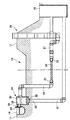
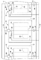
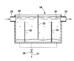
図は本発明の地下灌漑システムにおける用水供給装置の一形態例を示すもので、図1は地下灌漑システムの断面図、図2は地下灌漑システムにおける配管系統を示す概略平面図、図3は沈殿槽の一例を示す断面図である。
【0009】
まず、図1及び図2に示すように、圃場の内部は、農道11や畦畔12によって複数の耕作区13に区画されており、一方の農道部分には給水路14が設けられ、他方の農道部分には排水路15が設けられるとともに、各耕作区13には、地下灌漑システムがそれぞれ設けられている。なお、給水路や排水路は圃場の状況に応じて任意の位置に設けることができ、畦畔の部分に設けられていることもある。
【0010】
地下灌漑システムは、耕作区13の地中に、給水用集合管21及び排水用集合管22に両端がそれぞれ接続した複数の有孔管23を並列に等間隔で埋設するとともに、前記給水用集合管21には、沈殿槽24を介して前記給水路14に接続する給水管25を設け、前記排水用集合管22には、水位設定器26を介して前記排水路15に至る排水管27を設けたものであって、水位設定器26によって耕作区13からの排水水位を調節することにより、各耕作区13の水位を任意に設定できるように形成されている。
【0011】
前記沈殿槽24は、給水路14に開口する取水管28が接続される流入側開口29と、前記給水管25が接続される流出側開口30とを槽上部にそれぞれ設けるとともに、槽底部に沈殿した土砂を排出するための排泥管31を接続する排泥口32を設けたものであって、流入側開口29から流入して流出側開口30から流出する用水の流速を、土砂が沈降可能な範囲で十分に遅くできる大きさを備えている。また、図3に示すように、沈殿槽24の内部に、用水の流れを制御するための1枚以上の邪魔板33を設けておくことにより、土砂等を含んだ用水が流入側開口28から流出側開口29に短絡した状態で流れることを防止でき、より効果的に土砂の沈降分離を行うことができる。
【0012】
なお、取水管28の取入口には、配管経路内で詰まるおそれのある粗大なゴミを分離するための目の粗いフィルター34を設けておくことができ、取水量を調節するための弁や堰、取水量を確認するための流量確認手段等を設けておくこともできる。また、沈殿槽24の上部開口は蓋で塞いでおくことが望ましい。
【0013】
このように、給水路14からの用水を前記有孔管23に供給する経路の途中に沈殿槽24を設けることにより、用水中の土砂等を沈殿槽24で沈降分離することができるので、給水管25から有孔管23に用水とともに土砂等が流入することを防止できる。これにより、長期間の使用においても、有孔管23内に土砂等が蓄積して有孔管23の通水性能を阻害することがなくなる。
【0014】
したがって、取水口に目の細かいフィルターを設置したりする必要がなくなるので、日常的な保守点検作業を省略することが可能となり、農作業の省力化を図ることができる。
【0015】
沈殿槽24内に沈降した土砂等は、排泥口32を塞ぐようにして設けられた止水栓35を取り除いて沈殿槽24内を排泥管31に連通させることにより、沈殿槽24内の用水と共に槽底部に沈殿した土砂を排泥管31から排水路15に向けて排水することができる。なお、止水栓35に代えて排泥管30の途中に弁や水閘36を設けたり、排泥管31の端部に止水キャップをねじ込むようにしておくこともできる。また、排泥口32を設けずに、ポンプで沈殿槽24内の用水と共に土砂等を吸い込んで排出するようにしてもよく、手作業で土砂等を掻き出すようにしてもよい。
【0016】
また、沈殿槽24は、角形や円形の枡を1個以上使用して形成することができるが、大径のパイプを農道11や畦畔12に沿って水平方向に設置するようにしてもよい。
【0017】
なお、水位設定器26による水位の設定操作は、従来と同じようにしてできるので、その詳細な説明は省略する。また、水位設定器26の構造は任意であり、水位の設定範囲も任意である。
【0018】
【発明の効果】
以上説明したように、本発明の地下灌漑システムによれば、給水路から供給される用水中に土砂等が多く含まれていても、沈殿槽で土砂等を沈降させて用水から分離することができるので、地下灌漑を行うための有孔管内に土砂等が流入することを防止でき、長期間にわたって確実な地下灌漑を行うことができる。
【図面の簡単な説明】
【図1】本発明を適用した地下灌漑システムの一形態例を示す断面図である。
【図2】本発明を適用した地下灌漑システムにおける配管系統を示す概略平面図である。
【図3】沈殿槽の一例を示す断面図である。
【符号の説明】
11…農道、12…畦畔、13…耕作区、14…給水路、15…排水路、21…給水用集合管、22…排水用集合管、23…有孔管、24…沈殿槽、25…給水管、26…水位設定器、27…排水管、28…取水管、29…流入側開口、30…流出側開口、31…排泥管、32…排泥口、33…邪魔板、34…フィルター、35…止水栓、36…水閘[0001]
TECHNICAL FIELD OF THE INVENTION
The present invention relates to a water supply device in an underground irrigation system, and more particularly, to a perforated pipe in an underground irrigation system for setting a groundwater level or a surface water level in a field by adjusting a drainage water level from a perforated pipe buried underground. The present invention relates to an apparatus for supplying water to water.
[0002]
[Prior art]
Underground irrigation, which has been practiced in recent years, replenishes water by capillary action by adjusting the groundwater level in the field during upland cultivation, and improving the yield by adjusting the groundwater level to a water level suitable for crops. The effect can be obtained. In this underground irrigation, a culvert drainage pipe consisting of a perforated pipe is buried in the ground of the field to discharge the excess groundwater underground to the drainage channel, and to supply insufficient water using the culvert drainage pipe. Is common (for example, see Patent Document 1).
[0003]
[Patent Document 1]
JP-A-10-155375 (page 2, FIG. 1, FIG. 2)
[0004]
[Problems to be solved by the invention]
In underground irrigation as described above, depending on the local conditions of the field, the supplied irrigation water may contain a large amount of dirt and earth and sand. There is a possibility that water will accumulate and impede the water flow performance. Therefore, when using irrigation water containing a large amount of soil and the like for underground irrigation, it was necessary to install a fine filter at a portion where the irrigation water is taken into the underground irrigation system from the water supply channel. However, if such measures are taken, maintenance requires much labor.
[0005]
Therefore, the present invention can prevent the accumulation of sediment and the like in the culvert drainage pipe (perforated pipe) even when the service water contains a large amount of sediment and the like, and perform reliable underground irrigation, and also facilitate maintenance work. It is an object of the present invention to provide a water supply device for an underground irrigation system that can be performed in a country.
[0006]
[Means for Solving the Problems]
In order to achieve the above object, the water supply device in the underground irrigation system of the present invention embeds a perforated pipe in the ground of a field and installs a water level setting device downstream of the perforated pipe, In the underground irrigation system for setting the water level of the field by adjusting the drainage water level by, in order to settle and separate the sediment contained in the water, on the way to supply the water from the water supply channel to the perforated pipe Is provided.
[0007]
Further, the sedimentation tank is provided with a drainage pipe for discharging sediment deposited at the bottom, and the sedimentation tank is provided with a baffle plate for controlling a flow of water. .
[0008]
BEST MODE FOR CARRYING OUT THE INVENTION
FIG. 1 shows an embodiment of a water supply device in an underground irrigation system of the present invention. FIG. 1 is a sectional view of the underground irrigation system, FIG. 2 is a schematic plan view showing a piping system in the underground irrigation system, and FIG. It is sectional drawing which shows an example of a tank.
[0009]
First, as shown in FIG. 1 and FIG. 2, the inside of the field is divided into a plurality of
[0010]
In the underground irrigation system, a plurality of
[0011]
The
[0012]
The intake of the
[0013]
In this way, by providing the
[0014]
Therefore, it is not necessary to install a fine filter in the water intake, so that it is possible to omit daily maintenance and inspection work, and it is possible to save labor for agricultural work.
[0015]
The sediment or the like settled in the
[0016]
Further, the
[0017]
The operation of setting the water level by the water
[0018]
【The invention's effect】
As described above, according to the underground irrigation system of the present invention, even if the irrigation water supplied from the water supply channel contains much sediment, the sediment can be settled in the sedimentation tank and separated from the irrigation water. Since it is possible, soil and the like can be prevented from flowing into the perforated pipe for performing underground irrigation, and reliable underground irrigation can be performed for a long period of time.
[Brief description of the drawings]
FIG. 1 is a cross-sectional view showing one embodiment of an underground irrigation system to which the present invention is applied.
FIG. 2 is a schematic plan view showing a piping system in an underground irrigation system to which the present invention has been applied.
FIG. 3 is a sectional view showing an example of a sedimentation tank.
[Explanation of symbols]
11 ... farm road, 12 ... ridge, 13 ... cultivation area, 14 ... water supply channel, 15 ... drainage channel, 21 ... water supply collecting pipe, 22 ... drainage collecting pipe, 23 ... perforated pipe, 24 ... sedimentation tank, 25 ... water supply pipe, 26 ... water level setting device, 27 ... drain pipe, 28 ... intake pipe, 29 ... inflow side opening, 30 ... outflow side opening, 31 ... mud pipe, 32 ... mud outlet, 33 ... baffle plate, 34 ... filter, 35 ... water stopcock, 36 ... water lock
Claims (3)
Priority Applications (1)
| Application Number | Priority Date | Filing Date | Title |
|---|---|---|---|
| JP2003035027A JP3702329B2 (en) | 2003-02-13 | 2003-02-13 | Water supply equipment for underground irrigation system |
Applications Claiming Priority (1)
| Application Number | Priority Date | Filing Date | Title |
|---|---|---|---|
| JP2003035027A JP3702329B2 (en) | 2003-02-13 | 2003-02-13 | Water supply equipment for underground irrigation system |
Publications (2)
| Publication Number | Publication Date |
|---|---|
| JP2004242562A true JP2004242562A (en) | 2004-09-02 |
| JP3702329B2 JP3702329B2 (en) | 2005-10-05 |
Family
ID=33020562
Family Applications (1)
| Application Number | Title | Priority Date | Filing Date |
|---|---|---|---|
| JP2003035027A Expired - Lifetime JP3702329B2 (en) | 2003-02-13 | 2003-02-13 | Water supply equipment for underground irrigation system |
Country Status (1)
| Country | Link |
|---|---|
| JP (1) | JP3702329B2 (en) |
Cited By (4)
| Publication number | Priority date | Publication date | Assignee | Title |
|---|---|---|---|---|
| JP2005021125A (en) * | 2003-07-02 | 2005-01-27 | Padei Kenkyusho:Kk | Water-supply pit for sub-irrigation |
| CN101953286A (en) * | 2010-08-24 | 2011-01-26 | 甘肃农业大学 | Automatic desilting control device and method for drop-irrigation head of multi-sand driven well |
| JP2018148835A (en) * | 2017-03-13 | 2018-09-27 | 株式会社クボタケミックス | Subirrigation system |
| CN112690192A (en) * | 2020-12-23 | 2021-04-23 | 石河子大学 | A Surface-Groundwater Combined Irrigation Method in Different Irrigation Periods |
-
2003
- 2003-02-13 JP JP2003035027A patent/JP3702329B2/en not_active Expired - Lifetime
Cited By (5)
| Publication number | Priority date | Publication date | Assignee | Title |
|---|---|---|---|---|
| JP2005021125A (en) * | 2003-07-02 | 2005-01-27 | Padei Kenkyusho:Kk | Water-supply pit for sub-irrigation |
| CN101953286A (en) * | 2010-08-24 | 2011-01-26 | 甘肃农业大学 | Automatic desilting control device and method for drop-irrigation head of multi-sand driven well |
| CN101953286B (en) * | 2010-08-24 | 2011-12-28 | 甘肃农业大学 | Automatic desilting control device and method for drop-irrigation head of multi-sand driven well |
| JP2018148835A (en) * | 2017-03-13 | 2018-09-27 | 株式会社クボタケミックス | Subirrigation system |
| CN112690192A (en) * | 2020-12-23 | 2021-04-23 | 石河子大学 | A Surface-Groundwater Combined Irrigation Method in Different Irrigation Periods |
Also Published As
| Publication number | Publication date |
|---|---|
| JP3702329B2 (en) | 2005-10-05 |
Similar Documents
| Publication | Publication Date | Title |
|---|---|---|
| KR101218344B1 (en) | Vegetative Filter For Primary Stage Rainwater Treatment | |
| KR20090033663A (en) | Vertical Initial Rainwater Purifier | |
| US10174494B2 (en) | Water treatment apparatus | |
| CN111101585B (en) | Road rainwater runoff pollution control and purification system | |
| AU2010291874B2 (en) | An arrangement and method for facilitating water usage | |
| CN106894337A (en) | Bridge floor sewage water treatment method | |
| KR102292290B1 (en) | LID road and street tree penetration facilities | |
| JPH05132993A (en) | Rainwater filter and maintaining method for its device and rainwater filtering method and its controlling equipment | |
| CN105887618B (en) | Road drainage processing unit and its water discharge method | |
| CN105201040B (en) | Catch basin with incipient rain separation and purification function | |
| JP3702329B2 (en) | Water supply equipment for underground irrigation system | |
| KR100892834B1 (en) | Detachable sedimentation tank system device with various particle filtering function, quantity control, purification and water permeation | |
| KR20150091603A (en) | Drain System for road having plug-prevent function | |
| JP3671373B2 (en) | Underground irrigation system | |
| JP2004180529A (en) | Underground irrigation system | |
| KR100988864B1 (en) | Water treatment system | |
| CN107034766B (en) | Highway sewage treatment structure and its processing method | |
| CN209082658U (en) | A kind of town road drainage system | |
| CN104179240A (en) | Rainwater infiltration well | |
| KR101313042B1 (en) | Device for inflow of rainwater and separating of earth and sand | |
| JP4544611B2 (en) | Water level adjustment system | |
| KR101888595B1 (en) | Small-scale sedimentation purification equipment for low-impact development facilities | |
| JP4596869B2 (en) | Water level control system in cultivated area | |
| CN204753370U (en) | Bridge draining system | |
| CN214497030U (en) | A detention belt for municipal roads with purification function |
Legal Events
| Date | Code | Title | Description |
|---|---|---|---|
| A977 | Report on retrieval |
Free format text: JAPANESE INTERMEDIATE CODE: A971007 Effective date: 20050307 |
|
| A131 | Notification of reasons for refusal |
Free format text: JAPANESE INTERMEDIATE CODE: A131 Effective date: 20050315 |
|
| A521 | Request for written amendment filed |
Free format text: JAPANESE INTERMEDIATE CODE: A523 Effective date: 20050516 |
|
| TRDD | Decision of grant or rejection written | ||
| A01 | Written decision to grant a patent or to grant a registration (utility model) |
Free format text: JAPANESE INTERMEDIATE CODE: A01 Effective date: 20050614 |
|
| A61 | First payment of annual fees (during grant procedure) |
Free format text: JAPANESE INTERMEDIATE CODE: A61 Effective date: 20050622 |
|
| R150 | Certificate of patent or registration of utility model |
Ref document number: 3702329 Country of ref document: JP Free format text: JAPANESE INTERMEDIATE CODE: R150 Free format text: JAPANESE INTERMEDIATE CODE: R150 |
|
| S111 | Request for change of ownership or part of ownership |
Free format text: JAPANESE INTERMEDIATE CODE: R313115 |
|
| R350 | Written notification of registration of transfer |
Free format text: JAPANESE INTERMEDIATE CODE: R350 |
|
| FPAY | Renewal fee payment (event date is renewal date of database) |
Free format text: PAYMENT UNTIL: 20090729 Year of fee payment: 4 |
|
| R250 | Receipt of annual fees |
Free format text: JAPANESE INTERMEDIATE CODE: R250 |
|
| FPAY | Renewal fee payment (event date is renewal date of database) |
Free format text: PAYMENT UNTIL: 20100729 Year of fee payment: 5 |
|
| R250 | Receipt of annual fees |
Free format text: JAPANESE INTERMEDIATE CODE: R250 |
|
| FPAY | Renewal fee payment (event date is renewal date of database) |
Free format text: PAYMENT UNTIL: 20110729 Year of fee payment: 6 |
|
| R250 | Receipt of annual fees |
Free format text: JAPANESE INTERMEDIATE CODE: R250 |
|
| FPAY | Renewal fee payment (event date is renewal date of database) |
Free format text: PAYMENT UNTIL: 20120729 Year of fee payment: 7 |
|
| R250 | Receipt of annual fees |
Free format text: JAPANESE INTERMEDIATE CODE: R250 |
|
| FPAY | Renewal fee payment (event date is renewal date of database) |
Free format text: PAYMENT UNTIL: 20120729 Year of fee payment: 7 |
|
| FPAY | Renewal fee payment (event date is renewal date of database) |
Free format text: PAYMENT UNTIL: 20130729 Year of fee payment: 8 |
|
| R250 | Receipt of annual fees |
Free format text: JAPANESE INTERMEDIATE CODE: R250 |
|
| R250 | Receipt of annual fees |
Free format text: JAPANESE INTERMEDIATE CODE: R250 |
|
| R250 | Receipt of annual fees |
Free format text: JAPANESE INTERMEDIATE CODE: R250 |
|
| S533 | Written request for registration of change of name |
Free format text: JAPANESE INTERMEDIATE CODE: R313533 |
|
| R350 | Written notification of registration of transfer |
Free format text: JAPANESE INTERMEDIATE CODE: R350 |
|
| R250 | Receipt of annual fees |
Free format text: JAPANESE INTERMEDIATE CODE: R250 |
|
| R250 | Receipt of annual fees |
Free format text: JAPANESE INTERMEDIATE CODE: R250 |
|
| R250 | Receipt of annual fees |
Free format text: JAPANESE INTERMEDIATE CODE: R250 |
|
| R250 | Receipt of annual fees |
Free format text: JAPANESE INTERMEDIATE CODE: R250 |
|
| R250 | Receipt of annual fees |
Free format text: JAPANESE INTERMEDIATE CODE: R250 |
|
| R250 | Receipt of annual fees |
Free format text: JAPANESE INTERMEDIATE CODE: R250 |
|
| R250 | Receipt of annual fees |
Free format text: JAPANESE INTERMEDIATE CODE: R250 |
|
| R250 | Receipt of annual fees |
Free format text: JAPANESE INTERMEDIATE CODE: R250 |
|
| EXPY | Cancellation because of completion of term |