JP2004247307A - Temperature control system of heater - Google Patents
Temperature control system of heater Download PDFInfo
- Publication number
- JP2004247307A JP2004247307A JP2004035260A JP2004035260A JP2004247307A JP 2004247307 A JP2004247307 A JP 2004247307A JP 2004035260 A JP2004035260 A JP 2004035260A JP 2004035260 A JP2004035260 A JP 2004035260A JP 2004247307 A JP2004247307 A JP 2004247307A
- Authority
- JP
- Japan
- Prior art keywords
- drum
- temperature
- power
- electrical
- temperature control
- Prior art date
- Legal status (The legal status is an assumption and is not a legal conclusion. Google has not performed a legal analysis and makes no representation as to the accuracy of the status listed.)
- Pending
Links
- 238000005485 electric heating Methods 0.000 claims description 8
- 238000010438 heat treatment Methods 0.000 description 26
- 238000004891 communication Methods 0.000 description 14
- 238000012545 processing Methods 0.000 description 11
- 238000000034 method Methods 0.000 description 10
- 230000003287 optical effect Effects 0.000 description 8
- 238000011161 development Methods 0.000 description 7
- 229910052709 silver Inorganic materials 0.000 description 6
- 239000004332 silver Substances 0.000 description 6
- 239000007787 solid Substances 0.000 description 6
- 238000010586 diagram Methods 0.000 description 5
- -1 silver halide Chemical class 0.000 description 5
- 239000000758 substrate Substances 0.000 description 5
- 230000001629 suppression Effects 0.000 description 5
- 230000008569 process Effects 0.000 description 4
- XUIMIQQOPSSXEZ-UHFFFAOYSA-N Silicon Chemical compound [Si] XUIMIQQOPSSXEZ-UHFFFAOYSA-N 0.000 description 3
- 239000011248 coating agent Substances 0.000 description 3
- 238000000576 coating method Methods 0.000 description 3
- 229910052710 silicon Inorganic materials 0.000 description 3
- 239000010703 silicon Substances 0.000 description 3
- 238000004364 calculation method Methods 0.000 description 2
- 238000001816 cooling Methods 0.000 description 2
- 239000000463 material Substances 0.000 description 2
- 230000007246 mechanism Effects 0.000 description 2
- BASFCYQUMIYNBI-UHFFFAOYSA-N platinum Chemical compound [Pt] BASFCYQUMIYNBI-UHFFFAOYSA-N 0.000 description 2
- GGCZERPQGJTIQP-UHFFFAOYSA-N sodium;9,10-dioxoanthracene-2-sulfonic acid Chemical compound [Na+].C1=CC=C2C(=O)C3=CC(S(=O)(=O)O)=CC=C3C(=O)C2=C1 GGCZERPQGJTIQP-UHFFFAOYSA-N 0.000 description 2
- BQCADISMDOOEFD-UHFFFAOYSA-N Silver Chemical compound [Ag] BQCADISMDOOEFD-UHFFFAOYSA-N 0.000 description 1
- FOIXSVOLVBLSDH-UHFFFAOYSA-N Silver ion Chemical compound [Ag+] FOIXSVOLVBLSDH-UHFFFAOYSA-N 0.000 description 1
- XAGFODPZIPBFFR-UHFFFAOYSA-N aluminium Chemical compound [Al] XAGFODPZIPBFFR-UHFFFAOYSA-N 0.000 description 1
- 229910052782 aluminium Inorganic materials 0.000 description 1
- 230000000712 assembly Effects 0.000 description 1
- 238000000429 assembly Methods 0.000 description 1
- 239000011230 binding agent Substances 0.000 description 1
- 238000009529 body temperature measurement Methods 0.000 description 1
- 238000003490 calendering Methods 0.000 description 1
- 238000006243 chemical reaction Methods 0.000 description 1
- 239000003638 chemical reducing agent Substances 0.000 description 1
- 238000013461 design Methods 0.000 description 1
- 238000003745 diagnosis Methods 0.000 description 1
- 238000001035 drying Methods 0.000 description 1
- 239000000839 emulsion Substances 0.000 description 1
- 238000005516 engineering process Methods 0.000 description 1
- 238000003384 imaging method Methods 0.000 description 1
- 238000010030 laminating Methods 0.000 description 1
- 239000007788 liquid Substances 0.000 description 1
- 238000004519 manufacturing process Methods 0.000 description 1
- 230000002093 peripheral effect Effects 0.000 description 1
- 229910052697 platinum Inorganic materials 0.000 description 1
- 230000005855 radiation Effects 0.000 description 1
- 230000009467 reduction Effects 0.000 description 1
- 230000004044 response Effects 0.000 description 1
- 239000000126 substance Substances 0.000 description 1
- 238000010792 warming Methods 0.000 description 1
- XLYOFNOQVPJJNP-UHFFFAOYSA-N water Substances O XLYOFNOQVPJJNP-UHFFFAOYSA-N 0.000 description 1
Images


Classifications
-
- H—ELECTRICITY
- H05—ELECTRIC TECHNIQUES NOT OTHERWISE PROVIDED FOR
- H05B—ELECTRIC HEATING; ELECTRIC LIGHT SOURCES NOT OTHERWISE PROVIDED FOR; CIRCUIT ARRANGEMENTS FOR ELECTRIC LIGHT SOURCES, IN GENERAL
- H05B1/00—Details of electric heating devices
- H05B1/02—Automatic switching arrangements specially adapted to apparatus ; Control of heating devices
- H05B1/0227—Applications
- H05B1/023—Industrial applications
- H05B1/0241—For photocopiers
-
- G—PHYSICS
- G05—CONTROLLING; REGULATING
- G05D—SYSTEMS FOR CONTROLLING OR REGULATING NON-ELECTRIC VARIABLES
- G05D23/00—Control of temperature
- G05D23/19—Control of temperature characterised by the use of electric means
- G05D23/1951—Control of temperature characterised by the use of electric means with control of the working time of a temperature controlling device
Landscapes
- Physics & Mathematics (AREA)
- General Physics & Mathematics (AREA)
- Engineering & Computer Science (AREA)
- Automation & Control Theory (AREA)
- Control Of Resistance Heating (AREA)
- Photographic Developing Apparatuses (AREA)
- Control Of Temperature (AREA)
Abstract
Description
本発明は、温度制御装置に関し、より詳細には、フリッカを削減するように温度制御加熱器の温度を制御する装置に関する。 The present invention relates to a temperature control device, and more particularly, to a device for controlling the temperature of a temperature control heater so as to reduce flicker.
乾式銀塩写真方式(photothermography)は、1つの確立した画像形成技術である。乾式銀塩写真方式において、感光性媒体が放射線により露光されると、この媒体に熱処理で現像可能な潜像が形成される。この熱現像処理を実施できる装置および方法は、一般に知られており、その中には、画像が形成された感光性媒体を加熱プラテン、加熱ドラム、または加熱ベルトと接触させ、該媒体に加熱空気を吹き付け、加熱された不活性液に該媒体を浸し、更に、該媒体が感光しない波長、たとえば、赤外線波長の放射エネルギで該媒体を露光する装置および方法が含まれる。これらの従来技術においては、特に、加熱ドラムの利用が一般的である。 Dry silver halide photothermography is an established imaging technology. In a dry silver halide photographic system, when a photosensitive medium is exposed to radiation, a latent image that can be developed by heat treatment is formed on the medium. Apparatuses and methods capable of performing this thermal development process are generally known, including contacting an imaged photosensitive medium with a heated platen, heated drum, or heated belt and applying heated air to the medium. And immersing the medium in a heated inert liquid, and further exposing the medium with radiant energy at a wavelength to which the medium is not sensitive, for example, infrared wavelengths. In these prior arts, the use of a heating drum is particularly common.
これらの画像形成処理に利用できる一般的な感光性媒体は、フィルム、紙などの熱現像感光性媒体として知られる。1つの熱現像感光性媒体は、結合剤と、ハロゲン化銀と、有機銀塩(または、還元可能で非感光性の銀原料物質)と、銀イオン還元剤と、を有する。産業界において、これらの熱現像感光性媒体は、乾式銀塩フィルムを含む乾式銀塩媒体として知られている。 General photosensitive media that can be used in these image forming processes are known as heat-developable photosensitive media such as films and papers. One photothermographic medium has a binder, silver halide, an organic silver salt (or a reducible, non-photosensitive silver source material), and a silver ion reducing agent. In the industry, these photothermographic media are known as dry silver halide media, including dry silver halide films.
露光された熱現像感光性媒体(フィルムおよび紙を含む)を正確に加熱するには、電気的に加熱されたドラムを利用することが望ましいことがわかっている。この技術を採用する装置において、円筒ドラムは、熱現像感光性媒体の所定現像温度に近い温度まで加熱される。ドラムが、その長手方向の軸を中心に回転するとき、熱現像感光性媒体は、加熱ドラムのごく近傍に保持される。加熱ドラムの表面温度と、熱現像感光性媒体を近接して保持している外周部と、ドラムの回転速度とが判れば、熱現像感光性媒体の現像時間と現像温度を決定できる。一般に、これらのパラメータは、使用される特定の熱現像感光性媒体に応じて最適化されるが、場合によってはその熱現像感光性媒体が採用される用途も考慮される。 It has been found desirable to utilize an electrically heated drum for accurate heating of exposed photothermographic media (including film and paper). In an apparatus employing this technique, the cylindrical drum is heated to a temperature close to a predetermined developing temperature of the photothermographic medium. As the drum rotates about its longitudinal axis, the photothermographic medium is held in close proximity to the heated drum. The development time and the development temperature of the photothermographic medium can be determined by knowing the surface temperature of the heating drum, the outer peripheral portion where the photothermographic medium is held in close proximity, and the rotation speed of the drum. In general, these parameters will be optimized depending on the particular photothermographic medium used, but in some cases the application in which the photothermographic medium will be employed.
熱現像感光性媒体で高品質画像を達成するには、現像パラメータが非常に厳密に維持されなければならない。一般に、熱現像感光性媒体が送られてきて、また送られていくドラムの外周が、大きく変動することはない。また、ドラムの回転速度、すなわち、熱現像感光性媒体が熱処理装置の中を移動する速度についても、正確に保持され得るものである。ただし、ドラムの表面温度の制御と保持は、概してかなり困難である。 To achieve high quality images on photothermographic media, development parameters must be maintained very closely. Generally, the outer periphery of the drum to which the photothermographic medium is fed and which is fed is not largely changed. Further, the rotation speed of the drum, that is, the speed at which the photothermographic medium moves in the heat treatment apparatus, can be accurately maintained. However, controlling and maintaining the surface temperature of the drum is generally quite difficult.
また、不正確な処理に至る一因として、他の要因もある。熱現像感光性媒体が保持される場所のドラムに対する近接度は、熱現像感光性媒体内の感光乳剤が加熱される温度をある程度決定する。また、ドラムと熱現像感光性媒体の間に存在する異物は、ドラムから熱現像感光性媒体への熱の流れを妨害する可能性があり、ひいては、画像品質に影響する。 There are also other factors that contribute to incorrect processing. The proximity of the drum where the photothermographic medium is held to some extent determines the temperature at which the emulsion in the photothermographic medium is heated. In addition, foreign substances present between the drum and the photothermographic medium may obstruct the flow of heat from the drum to the photothermographic medium, and thus affect image quality.
多くの要因が画像品質に影響を与えるが、その要因の1つは、熱現像感光性媒体が現像される温度である。したがって、ドラムの表面温度が維持される精度は、熱現像感光性媒体の熱処理にとって重要である。 Many factors affect image quality, one of which is the temperature at which the photothermographic media is developed. Therefore, the accuracy with which the surface temperature of the drum is maintained is important for the heat treatment of the photothermographic medium.
ドラムの温度は多くの要因に左右される。その要因としては、熱がドラムに伝達される速度、ドラムの熱伝導率と熱慣性(thermal mass)、熱現像感光性媒体の熱慣性、速度、すなわち、処理される熱現像感光性媒体のシート数(シート状の熱現像感光性媒体が使用される場合)、周囲温度、熱処理がちょうど始まったところであるのか、または、熱処理が長時間運転の中程であるのかなどがある。 The temperature of the drum depends on many factors. The factors include the speed at which heat is transferred to the drum, the thermal conductivity and thermal mass of the drum, the thermal inertia and speed of the photothermographic media, ie, the sheet of photothermographic media being processed. The number (if a sheet of photothermographic media is used), the ambient temperature, whether the heat treatment has just begun, or whether the heat treatment is in the middle of a long run.
また、加熱ドラムは、他の各種材料処理用途に幅広く用いられる。他の利用例としては、たとえば、カレンダ加工(calendaring)、積層加工、被覆加工、乾燥などがある。 Further, the heating drum is widely used for other various material processing applications. Other applications include, for example, calendaring, laminating, coating, drying, and the like.
一般に、熱は、電気抵抗加熱要素を用いてこのようなドラムに伝達される。熱処理の実行中、加熱ドラムは回転しており、ドラムが回転している間に、電気抵抗加熱要素に電力を送ることが好ましいことから、移動および回転しているドラムに対して、定置電源、たとえば、標準の交流線から電力を送ることが好ましい。電力は、ドラムと結合されたスリップリングを利用してドラムに伝達することができる。 Generally, heat is transferred to such drums using electrical resistance heating elements. During the heat treatment, the heating drum is rotating, and it is preferable to send power to the electric resistance heating element while the drum is rotating, so that for the moving and rotating drum, a stationary power supply, For example, it is preferable to send power from a standard AC line. Power can be transferred to the drum using a slip ring coupled to the drum.
また、電気加熱ドラムの温度を正確に制御するには、ドラムの温度を感知する手段、および温度センサからの信号に応じて電気抵抗加熱器に与えられる電力を制御する手段が必要である。 Further, in order to accurately control the temperature of the electric heating drum, a means for sensing the temperature of the drum and a means for controlling electric power supplied to the electric resistance heater in accordance with a signal from the temperature sensor are required.
1996年12月3日に発行された発明者タナマチ(Tanamachi)他による米国特許第5,580,478号明細書(特許文献1)は、中央加熱ゾーンと、隣接する端部ゾーンとを別の電気抵抗加熱器で熱する加熱ドラム処理装置を開示する。電気加熱器の温度制御は、デューティサイクルの変調によって行われる。電気加熱器までの電源回路内の固体リレー(ソリッドステートリレー)は、ゼロクロス始動によってオンとオフが切り換えられる。 U.S. Pat. No. 5,580,478, issued to the inventor Tanamachi et al. On Dec. 3, 1996, separates a central heating zone from an adjacent end zone. A heating drum processing apparatus for heating with an electric resistance heater is disclosed. Temperature control of the electric heater is provided by modulation of the duty cycle. The solid state relay (solid state relay) in the power supply circuit up to the electric heater is switched on and off by zero-cross starting.
出力過渡変化は、網状に構成され互いに影響を及ぼし合う電源を共有する照明・光源システムに光のフリッカを引き起こす。フリッカ抑制の新しい規格が、最近、ヨーロッパにおいて法制化された。フリッカ抑制の一般的な技法は、抑制のための電子機器を装置へ追加することであり、これは製造費の増加を招いている。一般的な解決方法は、AC入力電源とそのゼロクロスとを、負荷に対するスループットパワーを調整する時点についての基準として利用することである。例として、1990年3月20日に発行された発明者グランド(Grund)による米国特許第4,908,956号明細書(特許文献2)、1999年5月25日に発行された発明者タカハシ(Takahashi)による米国特許第5,907,743号明細書(特許文献3)、2001年2月13日に発行された発明者グレーザ(Glaser)他による米国特許第6,188,208号明細書(特許文献4)などが挙げられる。上記各特許は、ゼロクロスを基準とした電源のオン/オフタイミングの調整方法がそれぞれ異なるが、電子回路を利用して実現している点は共通である。1998年10月6日に発行された発明者オスマン(Othman)他による米国特許第5,818,208号明細書(特許文献5)に記載された別の発明は、エレクトロニクスを利用して、電圧源変換端子のAC電源電圧と負荷電流を測定し、有効電流と無効電流の負荷を計算することによって、フリッカを削減するものである。 Output transients cause light flicker in lighting and light source systems that are arranged in a mesh and share mutually influencing power supplies. A new standard for flicker control has recently been legislated in Europe. A common technique for flicker suppression is to add electronics to the device for suppression, which has resulted in increased manufacturing costs. A common solution is to use the AC input power supply and its zero cross as a reference for when to adjust the throughput power to the load. By way of example, US Patent No. 4,908,956 by Grund, issued March 20, 1990 (Patent Document 2); Takahashi, inventor issued May 25, 1999. U.S. Pat. No. 5,907,743 to Takahashi; U.S. Pat. No. 6,188,208 to Glaser et al., Issued Feb. 13, 2001; (Patent Document 4). Although the above patents differ in the method of adjusting the power on / off timing based on the zero crossing, they are common in that they are implemented using an electronic circuit. Another invention, described in U.S. Pat. No. 5,818,208, issued to the inventor Othman et al. On Oct. 6, 1998, uses electronics to apply voltage. The flicker is reduced by measuring the AC power supply voltage and the load current of the source conversion terminal and calculating the loads of the active current and the reactive current.
2002年7月16日に発行された発明者タナマチ(Tanamachi)による米国特許第6,420,685B1号明細書(特許文献6)は、電気抵抗加熱器のフリッカを削減する制御システムと、電源と電気抵抗加熱器の間に接続された2方向固体スイッチ装置(2方向ソリッドステートスイッチ装置)と、2方向固体スイッチ装置を制御して、位相制御された各種異なるデューティサイクルの電流を加熱器に供給する制御回路と、を開示する。この制御回路は、スイッチ装置をランダムにオンに切り換える2進制御信号に応じて、加熱器の電力を効果的に上下させる。 U.S. Pat. No. 6,420,685B1 by Tanamachi, issued Jul. 16, 2002, discloses a control system that reduces flicker in an electric resistance heater, a power supply and a power supply. Two-way solid-state switch device (two-way solid-state switch device) connected between electric resistance heaters and two-way solid-state switch device are controlled to supply phase-controlled currents of various duty cycles to the heater. And a control circuit. This control circuit effectively raises and lowers the power of the heater in response to a binary control signal that randomly switches the switching device on.
このように、電気加熱システムのフリッカを制御する効果的で費用対効果の高い方法に対する要望がある。 Thus, there is a need for an effective and cost-effective method of controlling flicker in an electric heating system.
本発明によって、前述した要望および問題に対する解決方法が提供される。 The present invention provides a solution to the aforementioned needs and problems.
本発明の一態様によると、電気抵抗加熱器のフリッカを削減する温度制御システムが提供される。この温度制御システムは、少なくとも2つの電気負荷に分割される電気抵抗加熱器と、所定期間の連続した別の副期間において、前記少なくとも2つの電気負荷それぞれに繰り返し電気出力を供給する電力の供給源と、を含む。該システムにおいて、前記少なくとも2つの電気負荷に供給される電力の合計は、前記所定時間枠の中で前記電気抵抗加熱器に供給される全出力と等しい。 According to one aspect of the present invention, there is provided a temperature control system that reduces flicker in an electrical resistance heater. The temperature control system includes an electrical resistance heater that is divided into at least two electrical loads, and a power source that repeatedly supplies electrical power to each of the at least two electrical loads during another successive sub-period of a predetermined period. And In the system, the sum of the power supplied to the at least two electric loads is equal to the total power supplied to the electric resistance heater during the predetermined time period.
本発明は次の利点を有する。
1.フリッカ抑制が、追加の電気回路に依存せずに達成される。
2.効率的で費用対効果が高いフリッカ抑制である。
The present invention has the following advantages.
1. Flicker suppression is achieved without relying on additional electrical circuitry.
2. Efficient and cost effective flicker suppression.
本発明は、概して、温度制御され、フリッカが抑制された電気加熱ドラムを提供する。円筒ドラムは一表面を備え、軸廻りに回転可能である。電気加熱器は、前記円筒ドラムの表面と熱現象に関して結合された状態にある。円筒ドラムと組み合わせて回転不能に設けられ、スリップリングを通じて電気加熱器に結合される固体リレー(SSR)は、回転不能に設けられたマイクロプロセッサからの制御信号に応じて、電気加熱器への電気の流れを制御することによって温度を制御する。円筒ドラムと共に回転可能に設けられた温度センサ機構は、円筒ドラムの表面の温度を検知し、検知した温度を表す温度信号を生成する。円筒ドラムに対して回転不能に設けられたマイクロプロセッサは、前記温度信号に応じた制御信号を生成して、電気加熱ドラムの温度を制御する。この温度制御手段、温度センサ手段、および回転式マイクロプロセッサ手段と組み合わされる光学機構は、回転式温度センサ手段から回転不能マイクロプロセッサ手段への温度信号を光学的に結合する。 The present invention generally provides an electrically heated drum with controlled temperature and reduced flicker. The cylindrical drum has one surface and is rotatable about an axis. The electric heater is in thermal contact with the surface of the cylindrical drum. A solid state relay (SSR), which is non-rotatable in combination with the cylindrical drum and is coupled to the electric heater through a slip ring, responds to a control signal from a non-rotatably provided microprocessor to provide electric power to the electric heater. The temperature by controlling the flow of water. A temperature sensor mechanism rotatably provided with the cylindrical drum detects the temperature of the surface of the cylindrical drum and generates a temperature signal representing the detected temperature. A microprocessor provided non-rotatably with respect to the cylindrical drum generates a control signal according to the temperature signal to control the temperature of the electric heating drum. An optical mechanism in combination with the temperature control means, the temperature sensor means, and the rotating microprocessor means optically couples the temperature signal from the rotating temperature sensor means to the non-rotatable microprocessor means.
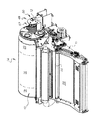
回転可能な電気加熱ドラム10を利用する熱処理装置の一部を図1および図2に示す。このような熱処理装置は、医療診断で要求される品質の乾式銀塩フィルムの処理に利用することができる。フレーム11上に取り付けられる円筒ドラム10は、軸線12回りに回転可能である。省略可能な構成として、ドラム10の外面14は、シリコン層15で被覆されてもよい。また、任意選択の構成として、ドラム10の外面14は、個別に制御される加熱ゾーン16,18,20に分割される。ドラム10の外面14の端部は、外面14の中央部分よりも温度が低くてもよいので、中央のゾーン16は、端部ゾーン18および20とは別に制御される。熱現象感光性媒体(図示せず)は、外面14とドラム10の近傍において、押さえつけローラ(図示せず)によってドラム10の外周部の上で保持される。ドラム10の外面14温度が分かり、典型的には華氏252度(摂氏122度)であるが、そして、回転速度が分かり、熱現象感光性媒体がその上を通過する外面14の外周部が分かれば、すでに知られている現像温度と休止時間を実現できる。加熱による現像の後、冷却装置22が、現像温度より低い温度まで熱現象感光性媒体を冷却する。冷却された媒体は、次に、排出トレイに搬送される。
A part of a heat treatment apparatus using a rotatable
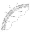
図2に示されるように、円筒ドラム10は、たとえば、8インチ(20.32センチメートル)の直径を持つアルミニウムで構成され、中空のドラム内部と、たとえば、0.25インチ(0.635センチメートル)の厚さの外殻とを備える。ドラム10の内面34に取り付けられる電気抵抗加熱器36,38,40は、それぞれ、加熱ゾーン16,18,20として適用される。ドラム10の外面14は、非常にきめ細かいシリコン被膜15を備える可能性があるため、ドラムの温度測定は、表面の被膜を傷つけないように内部において実行される。ドラム10の内面34に設けられた温度センサ(RTD:白金測温抵抗体)42,44,46は、それぞれ、各ゾーン16,18,20の温度を検知するように構成される。
As shown in FIG. 2, the
医療診断品質の画像を作成するため、外面14の温度は、ドラム10全域と、熱現象感光性媒体の各シートについて華氏±0.5度(摂氏±2.8度)内に維持される。
To create medical diagnostic quality images, the temperature of the
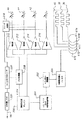
温度制御回路の主要構成部品の高レベルブロック図を図3に示す。ドラム10は回転するため、電気抵抗加熱器36,38,40との接続は、スリップリングアセンブリ67を介して実現される。スリップリングアセンブリ67は、円筒ドラム10の片側端部に設けられ、ドラム10と同じ速度で回転する。図3に示されるように、回路基板48は、この回転する回路基板48と光学的に協調動作するように位置決めされ、固定して設けられた受光器50と光学的に結合される。一方向の通信が、回転基板から光受信器50を介して回転しない処理装置通信基板52まで光通信リンク66を通じて発生する。回転回路基板48は、ドラム10と共に回転し、3つのドラム加熱ゾーン16,18,20から処理装置通信基板52に搭載されたソフトウェアまで、光受信器50に至るリンク66を介して温度情報を送信する。処理装置通信基板52は、マイクロプロセッサを含み、該マイクロプロセッサのソフトウェアが、3つの加熱ゾーン16,18,20から得たコード化された温度情報を解釈して、実際のゾーン温度に変換する。このソフトウェアは、次に、加熱制御アルゴリズムを用いて、特定のゾーンで検知された温度に対応する加熱器について、オンまたはオフのいずれに切り換えるのかを計算して、制御ループを閉じる。次に、マイクロプロセッサが、固体リレーをオンに切り換え、該当する加熱器に対して、スリップリングアセンブリ67A〜Eを通じて電力を付与する。
A high-level block diagram of the main components of the temperature control circuit is shown in FIG. As the
処理装置通信基板52の機能について、図4に、より詳しく示す。ドラム14が設けられた画像形成装置の電源70からのAC(交流)120ボルトは、基板52に伝達されて処理装置加熱器に与える電力であると共に、AC12ボルトの電力を回転基板に付与する。このAC12ボルトは、降圧変換器100を介して供給される。3つの固体リレー101,102,103が存在し、この固体リレーは、マイクロプロセッサ104の制御下で3つのドラム加熱器36,38,40それぞれへの電力を調整する。コード化された12ビットのデジタル温度データは、3つの各温度センサ42,44,46から光リンク66および光受信器50を介してマイクロプロセッサ104に供給される。画像形成装置の残りの部分への通信は、12Cインタフェース105を通じて行われる。また、新しいソフトウェアが、通信システムを介してダウンロードされてもよい。インタフェース105は、また、処理装置制御システムのサービスに対応するRS232通信ポートも含む。
FIG. 4 shows the function of the processing
図5を参照して説明する。図5には、回転ドラム10に配置される電気部品が詳細に示されている。スリップリング67A〜Dは、制御されたAC120ボルトの電力を抵抗加熱器36,38,40に供給する。また、AC12ボルトの電力が、スリップリング67Eを介して中継整流器とフィルタ200に供給され、+5ボルト調整器202に供給されるDC電圧を生成する。+2.5ボルト精密電圧基準器204および精密分圧器回路206は、アナログデジタル変換器208および電流源210〜216にDC(直流)電圧を供給する。電流源210,212,214は、それぞれ、温度センサ46,44,42と組み合わされる。各センサ42,44,46からの温度信号は、ロータリマイクロプロセッサ220によって制御されるアナログ多重器218に送られる。多重器218は、その温度信号をAD変換器208に供給してデジタル信号に変換する。変換されたデジタル信号は、マイクロプロセッサ220によって読み込まれて処理され、その後、マイクロプロセッサ220および赤外線LED222により光通信リンク66で通信される。
This will be described with reference to FIG. FIG. 5 shows the electric components arranged on the
本発明によると、フリッカは、作動時全体を通じてほぼ一定レベルの電力を複数の負荷に分配することによって抑制される。このフリッカ抑制解決方法には次に示すいくつかの構成要素がある。
1)負荷を2つ以上のより小さい負荷に分割する。
2)小さい負荷に対する電源のオンをそれぞれ、設定期間内の異なる時点で切り換える。この設定期間は、継続的に反復する。前記設定期間内において任意の特定の負荷に電力が与えられる時間長さのことを、該当する負荷の電力消費のデューティサイクルと呼ぶ。したがって、50パーセントのデューティサイクルは、電力が前記設定期間の半分の長さだけ与えられることを意味する。各負荷の最大デューティサイクルが、各負荷のスイッチの切換えの時間差に比例するように負荷が選択されるのが理想的である。そして、負荷Aは、負荷Bがオンに切り換わる時点またはそれ以前にオフに切り換わらなければならない。
3)負荷が切り換わる時間は、装置全体の電力消費に対する比率として、負荷の電力消費と比例する。このタイミングは位相と呼ばれる。たとえば、電力消費が4つの等分の負荷に分割される場合、各負荷は、前の負荷と位相が90度ずれてオンに切り換わる(360度で1周期になる)。負荷が3つであり、3つ目の負荷が残りの2つの倍の電力を消費する場合、2つの等しい負荷については、それぞれ0度と90度、3つ目の負荷については、180度の時点で切り換えを行える。3つ目の負荷がオンに切り換わった後は、期間の半分について、次に切り換わる負荷が存在しないことになる。この例について、更に、期間が2秒であるとする。その場合は、1つの負荷が0秒、もう1つの等価の負荷が2分の1秒、そして、大きい負荷が1秒の時点でオンに切り換わる。そして、2秒が経過した時点で再度全プロセスが反復し、続いて、2秒ごとに反復する。
According to the present invention, flicker is suppressed by distributing a substantially constant level of power to multiple loads throughout operation. This flicker suppression solution has several components as follows.
1) Divide the load into two or more smaller loads.
2) Switching on the power supply for a small load is switched at different times within a set period. This set period repeats continuously. The length of time during which power is supplied to any particular load within the set period is referred to as the duty cycle of power consumption of the load. Thus, a duty cycle of 50 percent means that power is provided for half the set period. Ideally, the loads are selected such that the maximum duty cycle of each load is proportional to the time difference between the switches of each load. The load A must be turned off at or before the time when the load B is turned on.
3) The time at which the load switches is proportional to the power consumption of the load as a ratio to the power consumption of the entire device. This timing is called a phase. For example, if power consumption is divided into four equal loads, each load switches on 90 degrees out of phase with the previous load (360 degrees forms one cycle). If there are three loads and the third load consumes twice the remaining power, then two equal loads at 0 and 90 degrees, respectively, and for the third load, 180 degrees. You can switch at that point. After the third load is switched on, there will be no load to be switched next for half of the period. For this example, further assume that the period is 2 seconds. In that case, one load switches on at 0 seconds, another equivalent load at half a second, and a large load switches on at 1 second. Then, when two seconds have elapsed, the entire process is repeated again, and subsequently, every two seconds.
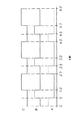
前述した熱処理装置の構成において、フリッカを抑制する本発明は、次の例に示す方法で実現されてもよい。電源70からのAC電力は、電気抵抗加熱器36,38,40に供給され、固定リレー101,102,103およびスリップリング67A,67B,67Cを通じて各ゾーン16,18,20を加熱する。リレー101,102,103は、マイクロプロセッサ104によって制御され、設定期間内の異なる時点において、電気抵抗加熱器36,38,40に電力を送る。前述の例において、加熱器38によって加熱される中央のゾーン16に供給される電力が、加熱器36,40によってそれぞれ加熱される各端部ゾーン18,20に供給される電力の2倍であると仮定すると、0秒の時点において、リレー103をオンに切り換えて加熱器36にXワットの電力が供給される。0.5秒の時点において、リレー103がオフに切り換えられ、加熱器36への電力供給が終了し、リレー101がオンに切り換えられて、Xワットの電力を加熱器40に供給する。1.0秒の時点において、リレー101はオフに切り換えられ、リレー102がオンに切り換えられて、2Xワットを加熱器38に供給する。2秒の時点において、加熱器38への電力供給は、リレー102をオフに切り換えて停止される。この処理は、続く2秒の期間ごとに再び反復される。この電力サイクルは、前述の信号を描画した図6に示されている。信号Aは、加熱器36に供給される電力を表し、信号Bは加熱器40に供給される電力、信号Cは加熱器38に供給される電力を表す。
In the configuration of the heat treatment apparatus described above, the present invention for suppressing flicker may be realized by a method shown in the following example. AC power from the
この例では、2秒の期間が使用されているが、これは、付与された電力の熱量一部が移動し。温度を検知するRTD(抵抗温度計)に到達するのに要する期間である。この期間は、適用例の熱設計によって異なるが、実際には、1秒〜2秒まで変更可能である。ゾーンの温度は、期間の終了時に測定され、そのゾーンの次の期間に対応するデューティサイクルの計算に利用される。デューティサイクルの計算は、比例積分微分(PID)温度制御アルゴリズムの計算である。前述したフリッカ制御は、この適用例のピーク電流負荷の大きさを3分の1に削減する。デューティサイクルは、実際には、最大負荷条件を示す図6に示されているものよりも小さかった。より短いデューティサイクルであっても、依然として、電流のピーク負荷消費のフリッカ制御による削減範囲内に留まる。 In this example, a period of 2 seconds is used, which transfers a portion of the applied heat. This is a period required to reach an RTD (resistance thermometer) for detecting temperature. This period varies depending on the thermal design of the application, but can be actually changed from 1 second to 2 seconds. The temperature of the zone is measured at the end of the period and is used to calculate the duty cycle corresponding to the next period of the zone. The duty cycle calculation is a calculation of a proportional integral derivative (PID) temperature control algorithm. The flicker control described above reduces the magnitude of the peak current load in this application example to one third. The duty cycle was actually smaller than that shown in FIG. 6, which shows the maximum load condition. Even with shorter duty cycles, the peak load consumption of the current still remains within the flicker control reduction range.
開始時の冷めた状態からドラムを暖める条件については、負荷電流のすべてが継続されることになる。この条件に対する実質的な温度制御は行わないため、電流の切り換え/フリッカは存在しない。ドラムが動作温度範囲に達したら、PID温度制御とフリッカ制御が開始する。 As for the condition for warming the drum from the cold state at the start, all of the load current will be continued. Since no substantial temperature control is performed for this condition, there is no current switching / flicker. When the drum reaches the operating temperature range, PID temperature control and flicker control start.
10 電気加熱ドラム、11 フレーム、14 外面、15 シリコン層、16,18,20 加熱ゾーン、22 冷却装置、36,38,40 電気抵抗加熱器、42,44,46 温度センサ、48 回路基板、50 受光器、52 処理装置通信基板、66光通信リンク、 67 スリップリングアセンブリ、70 電源、100 降圧変圧器、101,102,103 固体リレー、104 マイクロプロセッサ、105 12CとRS232通信インタフェース、200 中継整流器とフィルタ、202 +5ボルト整流器、204 +2.5ボルト精密電圧基準器、206 精密分圧器チェイン、208 AD変換器、210,212,214,216 電流源、218 アナログ多重器、222 赤外線LED。
Claims (3)
少なくとも2つの電気負荷に分割される電気抵抗加熱器と、
前記少なくとも2つの電気負荷それぞれに繰り返し電力を供給する電気出力の供給源であって、この供給源からの電力供給は、個々の電気負荷に対して所定の期間内の別個の副期間にて行われる、供給源と、
を含み、
前記少なくとも2つの電気負荷に供給される前記電力の合計は、前記所定期間の間に前記電気抵抗加熱器に供給される全電力と等しい、温度制御システム。 A temperature control system for reducing flicker of an electric resistance heater,
An electrical resistance heater divided into at least two electrical loads;
A source of electrical output for repeatedly supplying power to each of the at least two electrical loads, wherein power supply from the source is provided to the individual electrical loads in separate sub-periods within a predetermined time period. Source,
Including
The temperature control system, wherein a sum of the power supplied to the at least two electrical loads is equal to a total power supplied to the electric resistance heater during the predetermined time period.
軸廻りに回転可能で、該軸に沿って長手方向に配列される複数のゾーンに分割された外側表面を有する円筒ドラムと、
前記複数の各ゾーンに対して、それぞれ、熱的に結合される複数の電気抵抗加熱器と、
時間枠前記複数の電気抵抗加熱器それぞれに繰り返し電力を供給する電気出力の供給源であって、この供給源からの電力供給は、個々の電気負荷に対して所定の期間内の別個の副期間にて行われる、供給源と、
を含み、
前記複数の電気抵抗加熱器に供給される前記電力の合計は、前記所定時間枠の中で供給される全電力と等しい、電気加熱ドラムアセンブリ。 A temperature controlled electric heating drum assembly with reduced flicker, comprising:
A cylindrical drum rotatable about an axis and having an outer surface divided into a plurality of zones arranged longitudinally along the axis;
For each of the plurality of zones, respectively, a plurality of electric resistance heaters that are thermally coupled,
A time frame, a source of electrical output that repeatedly supplies power to each of the plurality of electrical resistance heaters, wherein the power supply from the source provides a separate sub-period within a predetermined period for each electrical load. And a source,
Including
The electric heating drum assembly, wherein a sum of the electric power supplied to the plurality of electric resistance heaters is equal to a total electric power supplied during the predetermined time frame.
Applications Claiming Priority (1)
| Application Number | Priority Date | Filing Date | Title |
|---|---|---|---|
| US10/365,789 US6849833B2 (en) | 2003-02-13 | 2003-02-13 | Logical flicker suppression for a temperature controlled heater load |
Publications (1)
| Publication Number | Publication Date |
|---|---|
| JP2004247307A true JP2004247307A (en) | 2004-09-02 |
Family
ID=32681722
Family Applications (1)
| Application Number | Title | Priority Date | Filing Date |
|---|---|---|---|
| JP2004035260A Pending JP2004247307A (en) | 2003-02-13 | 2004-02-12 | Temperature control system of heater |
Country Status (3)
| Country | Link |
|---|---|
| US (1) | US6849833B2 (en) |
| EP (1) | EP1447730A3 (en) |
| JP (1) | JP2004247307A (en) |
Families Citing this family (7)
| Publication number | Priority date | Publication date | Assignee | Title |
|---|---|---|---|---|
| GB2449651A (en) * | 2007-05-29 | 2008-12-03 | Ultra Electronics Ltd | Power control system to reduce imbalances |
| JP5744497B2 (en) * | 2010-12-09 | 2015-07-08 | キヤノン株式会社 | Image forming apparatus |
| US10119727B2 (en) * | 2015-05-06 | 2018-11-06 | Infineon Technologies Ag | Mechanical relay and solid-state relay for controlling heating elements |
| US11454677B2 (en) | 2016-07-01 | 2022-09-27 | Weber-Stephen Products Llc | Wireless control and status monitoring for electric grill with current protection circuitry |
| US10551893B2 (en) | 2016-07-01 | 2020-02-04 | Weber-Stephen Products Llc | Digital power supply with wireless monitoring and control |
| US10537199B2 (en) | 2016-07-01 | 2020-01-21 | Weber-Stephen Products Llc | Digital power supply |
| US10524312B2 (en) | 2016-07-01 | 2019-12-31 | Weber-Stephen Products Llc | Electric grill with current protection circuitry |
Family Cites Families (10)
| Publication number | Priority date | Publication date | Assignee | Title |
|---|---|---|---|---|
| GB8432542D0 (en) * | 1984-12-21 | 1985-02-06 | Micropore International Ltd | Power control arrangement |
| US4908956A (en) | 1989-03-28 | 1990-03-20 | Impact Systems, Inc. | Power controller for heater load |
| DE9314747U1 (en) * | 1993-09-30 | 1994-02-10 | Rowenta-Werke GmbH, 63071 Offenbach | Electrical circuit arrangement for the flicker standard-compliant and network feedback-free heating power control of heating resistors of electrical household appliances, in particular electrical bread toasters |
| US5580478A (en) | 1994-05-09 | 1996-12-03 | Minnesota Mining And Manufacturing Company | Apparatus for controlling the temperature of and a moveable, electrically heated object using two way on axis optical communication |
| EP0751442B1 (en) * | 1995-06-30 | 2010-11-03 | Canon Kabushiki Kaisha | Image heating apparatus |
| JPH10115997A (en) | 1996-10-09 | 1998-05-06 | Canon Inc | Power control device |
| US5818208A (en) | 1996-12-19 | 1998-10-06 | Abb Power T&D Company Inc. | Flicker controllers using voltage source converters |
| JP3847951B2 (en) * | 1997-04-30 | 2006-11-22 | キヤノン株式会社 | Heating control device |
| US6188208B1 (en) | 1999-08-02 | 2001-02-13 | General Electric Company | Cycle-skipping power control for AC line-powered loads |
| US6420685B1 (en) * | 2000-12-20 | 2002-07-16 | Eastman Kodak Company | Control of electrical heater to reduce flicker |
-
2003
- 2003-02-13 US US10/365,789 patent/US6849833B2/en not_active Expired - Lifetime
-
2004
- 2004-02-02 EP EP04075311A patent/EP1447730A3/en not_active Withdrawn
- 2004-02-12 JP JP2004035260A patent/JP2004247307A/en active Pending
Also Published As
| Publication number | Publication date |
|---|---|
| EP1447730A3 (en) | 2005-03-23 |
| EP1447730A2 (en) | 2004-08-18 |
| US6849833B2 (en) | 2005-02-01 |
| US20040159652A1 (en) | 2004-08-19 |
Similar Documents
| Publication | Publication Date | Title |
|---|---|---|
| US8509643B2 (en) | Fixing apparatus, image forming apparatus and fixing method | |
| CN100461027C (en) | Heating device, heating device control method, and non-contact heat sensing device | |
| JP2004247307A (en) | Temperature control system of heater | |
| JP3139416B2 (en) | Fixing device for image forming device | |
| JP2004280083A (en) | Image heating device | |
| JP2001100588A (en) | Heating device and image forming device | |
| JP2015102769A (en) | Image forming apparatus, temperature control method of fixing device, and program | |
| JP2019101251A (en) | Image heating device | |
| JP3796350B2 (en) | Heating device and image forming apparatus provided with the heating device | |
| JP2004234000A (en) | Temperature controller of movable electrically heated object/drum | |
| US6420685B1 (en) | Control of electrical heater to reduce flicker | |
| JP3391995B2 (en) | Heating body and heating device | |
| JP3777722B2 (en) | Fixing temperature control method | |
| JPH08190300A (en) | Heating device and image forming apparatus | |
| JP2002278350A (en) | Heating device and image forming device | |
| BE1011530A4 (en) | Photothermographic DEVELOPMENT SYSTEM. | |
| JPH1165351A (en) | Temperature control method and fixing device | |
| JP2025182927A (en) | Image forming device | |
| JPH08106234A (en) | Heating device | |
| JP2007212536A (en) | Image heating device | |
| JPS60135946A (en) | Picture recording device | |
| JP2005258143A (en) | Image forming apparatus | |
| JP2004179041A (en) | Heating equipment | |
| JPH112992A (en) | Fixing temperature control method | |
| JP2001066943A (en) | Fixing device |
Legal Events
| Date | Code | Title | Description |
|---|---|---|---|
| A621 | Written request for application examination |
Free format text: JAPANESE INTERMEDIATE CODE: A621 Effective date: 20070205 |
|
| A711 | Notification of change in applicant |
Free format text: JAPANESE INTERMEDIATE CODE: A711 Effective date: 20071227 |
|
| A131 | Notification of reasons for refusal |
Free format text: JAPANESE INTERMEDIATE CODE: A131 Effective date: 20080819 |
|
| A02 | Decision of refusal |
Free format text: JAPANESE INTERMEDIATE CODE: A02 Effective date: 20090203 |