JP2004248043A - Home network system, communication adapter and home controller used therefor - Google Patents
Home network system, communication adapter and home controller used therefor Download PDFInfo
- Publication number
- JP2004248043A JP2004248043A JP2003036778A JP2003036778A JP2004248043A JP 2004248043 A JP2004248043 A JP 2004248043A JP 2003036778 A JP2003036778 A JP 2003036778A JP 2003036778 A JP2003036778 A JP 2003036778A JP 2004248043 A JP2004248043 A JP 2004248043A
- Authority
- JP
- Japan
- Prior art keywords
- home
- control
- communication adapter
- unit
- information
- Prior art date
- Legal status (The legal status is an assumption and is not a legal conclusion. Google has not performed a legal analysis and makes no representation as to the accuracy of the status listed.)
- Granted
Links
Images


Landscapes
- Selective Calling Equipment (AREA)
Abstract
【課題】連携制御が重複している機器に無駄な運転や矛盾した動作が発生しないホームネットワークシステムと、これに用いる汎用性の高い通信アダプタとホームコントローラを提供すること。
【解決手段】複数の家電機器と、これら各家電機器をそれぞれホームネットワークへ接続するとともに家電機器を制御する制御プログラムが複数格納された通信アダプタと、この通信アダプタを介して家電機器を制御するホームコントローラとから構成されたホームネットワークシステムであって、ホームコントローラは、複数の家電機器が連携して制御する場合において、制御対象となる家電機器の制御条件に互いに矛盾した少なくとも2以上の指示内容が含まれる時、その各制御条件に対応する制御プログラムの中から適切な制御プログラムを予め選択する制御管理手段を設けるように構成した。
【選択図】 図1An object of the present invention is to provide a home network system in which useless operation and inconsistent operation do not occur in devices having cooperative control, and a highly versatile communication adapter and home controller used for the system.
A communication adapter storing a plurality of home appliances, a plurality of control programs for connecting each of the home appliances to a home network and controlling the home appliances, and a home for controlling the home appliances via the communication adapter. A home network system including a controller and a home controller, when a plurality of home appliances are controlled in cooperation with each other, at least two or more instruction contents inconsistent with each other in a control condition of a home appliance to be controlled. When included, a control management means for selecting an appropriate control program in advance from among the control programs corresponding to the respective control conditions is provided.
[Selection diagram] Fig. 1
Description
【0001】
【発明の属する技術分野】
本発明は、連携して動作する複数の家電機器を含むホームネットワークシステムと、これに用いる通信アダプタ及びホームコントローラに関するものである。
【0002】
【従来の技術】
従来のホームネットワークシステムでは、複数の家電機器にそれぞれサーバ機能を組込むと共に、各家電機器に対して個別に制御プログラムをインストールし、スケジュール運転や連携制御を行っていた(特許文献1参照)。
【0003】
【特許文献1】
特開2001−350676号公報
【0004】
【発明が解決しようとする課題】
従来のホームネットワークシステムは、以上のように構成されており、以下に示すような課題を有していた。
【0005】
システム内で連携制御が輻輳している場合、連携制御が重複する機器に対し、重複している連携制御のそれぞれから異なる内容のコマンド(例えば、ONコマンドとOFFコマンド)が、集中的に繰り返し送信されることがあった。この結果、重複する機器がチャタリングを起こしてしまうなど、システム全体として眺めてみた時、無駄な運転や矛盾した動作が発生するケースがあった。
【0006】
本発明は、係る課題を解決するためになされたもので、システム内で連携制御が輻輳した場合であっても、連携制御が重複している機器に無駄な運転や矛盾した動作が発生しないホームネットワークシステムと、これに用いる汎用性の高い通信アダプタとホームコントローラを提供することを目的にしている。
【0007】
【課題を解決するための手段】
本発明に係るホームネットワークシステムは、複数の家電機器と、これら各家電機器をそれぞれホームネットワークへ接続するとともに家電機器を制御する制御プログラムが複数格納された通信アダプタと、この通信アダプタを介して家電機器を制御するホームコントローラとから構成されたホームネットワークシステムであって、ホームコントローラは、複数の家電機器が連携して制御する場合において、制御対象となる家電機器の制御条件に互いに矛盾した少なくとも2以上の指示内容が含まれる時、その各制御条件に対応する制御プログラムの中から適切な制御プログラムを予め選択する制御管理手段を設けたものである。
【0008】
【発明の実施の形態】
実施の形態1.
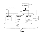
図1は、本発明の実施の形態1に係るホームネットワークシステムの全体構成図である。
図において有線または無線のホームネットワーク1には、複数の電気機器2とこれを監視・制御するための1個のホームコントローラ3が接続されている。
電気機器2は、それぞれに通信アダプタ4を介してホームネットワーク1に接続されるエアコン21a、換気扇21b、IH(Induction Heatingの略)調理器21c等の家電機器21やセンサなどの機器と、通信アダプタ4を介さずに直接接続されるパーソナルコンピュータ22などの機器に分けられる。
以下本文では、エアコン21a、換気扇21b、IH調理器21cに繋がる通信アダプタ4を区別する必要がある時は、品番4の後ろにa、b、cの添字を付けて表すことにする。
【0009】
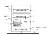
図2は、本発明の実施の形態1に係る通信アダプタ4の構成図である。
図において通信アダプタ4は、家電機器21に配設された入出力インタフェース部211と接続され、家電機器21との間でデータの交換を行う入出力インタフェース部41と、ホームネットワーク1を介してホームコントローラ3や他の電気機器2に繋がるネットワークインタフェース部44と、家電機器21を制御するための制御プログラムが複数格納されている記憶部42と、この記憶部42と入出力インタフェース部41とネットワークインタフェース部44の間でデータの処理と交換を行なう制御部43と、から構成されている。
【0010】
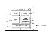
図3は、本発明の実施の形態1に係るホームコントローラ3の構成図である。
図においてホームコントローラ3は、ユーザが入力するためのタッチパネルやボタンなどの入力部31と、家電機器21の内部情報を表示するためのCRTやLCDなどの表示部32と、各設定データや通信アダプタ4に格納されている複数の制御プログラムに関する情報を記憶している記憶部33と、通信アダプタ4から接続先の家電機器21に関する情報を取得する機器情報取得手段38と各機器に設定された制御条件が適切であるかどうかを判断して適切な制御プログラムを選択する制御管理手段37を内蔵した制御部34と、ホームネットワーク1を介して他の電気機器2と繋がるネットワークインタフェース部35と、から構成されている。
【0011】
図示されていないが、換気扇21bに接続されている通信アダプタ4bでは、エアコン21aが稼動している情報を受け取ると、換気扇2bをOFFにする制御プログラムが選択されている。
また、IH調理器21cに接続されている通信アダプタ4cでは、IH調理器21cが稼動している情報を受け取ると、換気扇用の通信アダプタ4bに対して換気扇21bをONにする旨のコマンドを送信する制御プログラムが選択されている。
さらに、エアコン21aに接続されている通信アダプタ4aでは、室内の温度が27℃以上になると自動運転する制御プログラムが選択されている。
【0012】
次に図1〜3を参照にしながらホームネットワークシステムを構成するホームコントローラ3と通信アダプタ4の動作について説明する。
まず、ホームコントローラ3の機器情報取得手段38は、ホームネットワーク1に接続されている各通信アダプタ4(4a、4b、4c)に対し、それぞれに繋がる家電機器21(エアコン21a、換気扇21b、IH調理器21c)に関する情報を取得することを要求する機器情報要求フレームを作成して送信する。
【0013】
この機器情報要求フレームを受信した通信アダプタ4は、自身に接続されている家電機器21に関する情報や制御条件を取得した後、この内容を含んだ機器情報応答フレームを作成してホームネットワーク1へ送信する。
ここでIH調理器21cを例に取り上げて、通信アダプタ4が自身に接続されている家電機器21に関する情報を取得し、機器情報応答フレームを作成する動作について説明する。
【0014】
IH調理器21cに接続されている通信アダプタ4cは、IH調理器21cに対し、定期的に「機器状態」の情報を取得するための機器状態情報要求フレームを、入出力インタフェース部41を介して送信する。IH調理器21cは、この機器状態情報要求フレームを受信すると、自身の「機器状態」に関する情報を含んだ機器状態情報応答フレームを作成し、入出力インタフェース部211を介して通信アダプタ4cへ返信する。
【0015】
この機器状態情報応答フレームは、通信アダプタ4cの入出力インタフェース部41を介して制御部43により受信され、解釈される。これにより例えばIH調理器21cの「機器状態」が、「何Wで稼働中」、「停止中」などと解釈される。そして機器情報応答フレームには、こうして得られた「機器状態」に関する情報の他に、通信アダプタ4cの記憶部42に格納されている各種制御プログラムがどのような設定(機器及び制御条件)の下で使用できるかといった情報が、含まれている。
【0016】
このようにしてホームネットワーク1に繋がる全ての家電機器から「機器情報」を含んだ機器情報応答フレームが作成され、ホームネットワーク1へ送信される。これら機器情報応答フレームは全てホームコントローラ3で受信され、ホームコントローラ3には全ての家電機器に関する機器情報が集まる。
【0017】
そしてホームコントローラ3の機器情報取得手段38は、受信した機器情報応答フレームに基づいて、各機器において設定可能なパラメータや接続可能な機器情報などを含んだ制御条件を、表示部32へ送信する。これら機器及び制御条件は、表示部32に表示され、ユーザは、表示された機器及び制御条件を閲覧して連携動作する機器及び制御パラメータを設定する。
【0018】
ユーザが設定した機器及び制御パラメータは、ホームコントローラ3の制御管理手段37へ送信され、ここで、各機器に設定された制御条件が重複してないかどうか、特定の機器にチャタリングなどの矛盾した動作が発生しないかどうかがチェックされる。矛盾した動作が発生する場合には、重複している制御条件の中でどれを優先するかについて、記憶部33に格納されているテーブルに基づいて決定する。このテーブルは、出荷時に予めインストールされていても良いし、初動時にユーザが設定するようにしても良い。
【0019】
ここで初動時のユーザ設定について換気扇21b、エアコン21a、IH調理器21cによる連携制御を例に取り上げて説明する。
ユーザがIH調理器21cを使用し始めた場合を想定する。
IH調理器21cの使用と同時に、これに接続されている通信アダプタ4cの制御プログラムは、通信アダプタ4bに対して換気扇21bを起動(ON)させる旨のコマンドを送信する。このコマンドを受け取った通信アダプタ4bは、換気扇21bを起動(ON)させる。
【0020】
さらにIH調理器21cを使用し続けると、室内温度は上昇し、やがて所定温度(27℃)を越えてしまいエアコン21aが起動(ON)される。そしてエアコン21aが起動(ON)している情報を、換気扇21bに接続されている通信アダプタ4bで選択されている制御プログラムが、受け取ると、直ちに換気扇21bを停止(OFF)させる。
【0021】
このように換気扇21bにおいて、通信アダプタ4CによるON制御と通信アダプタ4bによるOFF制御が重複し、矛盾した動作が発生することが分かる。制御管理手段37は、このような矛盾した動作が発生しないように、予め各機器に設定された制御条件をチェックする。そしてこのチェックにより制御条件が重複し、特定の機器にチャタリングなどの矛盾した動作が発生すると判定された場合には、矛盾点として抽出され、予めこれを表示してユーザの判断をあおぐ。
【0022】
即ち、上記ケースでは、表示部32には、換気扇にエアコン21aによるコマンド(制御条件)とIH調理器21cによるコマンドが重複すること、及びどちらの制御を優先するかについてユ−ザの判断をあおぐ内容が表示される。
表示内容に基づき、例えばユーザが、快適性よりも安全性を考慮し、IH調理器21cによる制御の優先度を高く設定したとする。この設定内容は記憶部33に格納されると共に、制御管理手段37へ送られる。
【0023】
そして制御管理手段37はテーブル若しくは初動時に設定された内容に基づき、IH調理器21cが稼動中にエアコン21aがONになっても、換気扇21bをOFFに切換えない(ONのままに保つ)制御プログラムを、記憶部33に記憶されている各種制御プログラムに関する情報に基づいて選択する。この選択結果は、ネットワークインタフェース部35を介して通信アダプタ4bへ通知される。
【0024】
通信アダプタ4bは、この通知に基づいて記憶部42に格納されている各種制御プログラムの中から適切な制御プログラムを選択する。そして選択された制御プログラムにより、例えばユーザがIH調理器21cを使用して換気扇21bがONとなり、さらにIH調理器21cを使用し続けて室内温度が所定温度(27℃)を越えてしまいエアコン21aがONされても、換気扇2bには相反する内容のOFFコマンドが送信されることはなく、換気扇21bがチャタリングを起こすことはなくなる。
【0025】
このようにしてシステム内で連携制御が輻輳し、特定の機器に異なる内容のコマンドが重複して矛盾する動作が起こる場合であっても、予め制御管理手段37によってこれを抽出し、コマンドの優先度を設定させ、この設定に基づいて通信アダプタ4を制御する制御プログラムを選択し、この選択結果を通信アダプタ4へ送信するようにしたので、矛盾する動作を回避することが出来る。
【0026】
また本実施の形態では、快適性と安全性に係わる制御を例に取り上げて説明したが、省エネ性についても、他の制御と輻輳することによって特定の機器に異なる内容のコマンドが重複し、矛盾する動作が発生するようであれば、上記同様、予め優先度を定め、これに基づいて制御プログラムを選択するようにすれば回避できる。
【0027】
また、本実施の形態では、初期設定時に矛盾が生じないようにホームコントローラ3の制御管理手段37が、制御プログラムを選択する場合について説明したが、ホームコントローラ3の制御管理手段37により制御動作を直接監視し、矛盾が発生する場合のみ、これを解消するように制御しても良い。
【0028】
なお、本実施の形態では、複数の制御プログラムが通信アダプタ4の記憶部42に格納されている場合について説明したが、これら制御プログラムはホームコントローラ3の記憶部33に格納されていても良い。この場合、記憶部33には、各家電機器の制御条件と家電機器を制御するための通信アダプタ3の制御プログラムが複数格納されており、制御管理手段37は該制御条件の下、特定の機器に対し内容の異なるコマンドが重複することがないかどうかをチェックする。重複する場合は、上記と同様にして複数の制御プログラムの中から適切な制御プログラムを選択する。そして、この選択された制御プログラムはホームネットワーク1を介して通信アダプタ4へ送信(ダウンロード)され、家電機器21を制御するために供される。
【0029】
実施の形態2
実施の形態1では、接続される家電機器に対応した制御プログラムが、既に格納されている専用の通信アダプタについて説明した。本実施の形態では、接続される家電機器の変更に伴い、制御プログラムの書き換えが可能な汎用的な通信アダプタについて説明する。
【0030】
ホームネットワークシステム1の全体構成は、実施の形態1と同じであるので、説明を省略する。
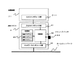
図4は、本発明の実施の形態に係る通信アダプタ4の構成図である。図において、実施の形態1と同一もしくは相当部分には同じ符号を付し、説明を省略する。実施の形態1で示した通信アダプタ4と比べると、新たに外部にリセットスイッチ444を配設した点が異なる。このリセットスイッチ444を押すことにより制御部43は、記憶部42を初期化する。
【0031】
図5は、本発明の実施の形態に係るホームコントローラ3の構成図である。実施の形態1で示したホームコントローラ3と比べると、制御部34内に新たにダウンロード手段36が追加されている。
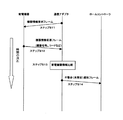
また図6は、本実施の形態に係る通信アダプタ4とホームコントローラ3との間におけるフレームのやり取りを示した通信シーケンスである。
以下、図4〜6を参照にしながらエアコン21aに接続していた通信アダプタ4aに電気カーペットを接続し、使用する制御プログラムを書換える手順について説明する。
【0032】
ユーザは通信アダプタ4aを電気カーペットに新たに接続した後、リセットボタン444を押す(ステップS1)。これにより通信アダプタ4aの制御部43は記憶部42を初期化し、ネットワークインタフェース部44を介してホームコントローラ3に対してダウンロードを要求するダウンロード要求フレームを作成して送信する(ステップS2)。ダウンロード要求フレームを受信したホームコントローラ3はダウンロード手段36により、ホームコントローラ3の記憶部33に格納してある制御プログラムを表示部32に表示させる。
【0033】
ユーザは表示された家電機器21の制御プログラムの中から、対象機器(電気カーペット)用の制御プログラムを入力部31より選択する(ステップS3)。ダウンロード手段36は入力部31より選択された制御プログラムを記憶部33から取り出す(ステップS4)。そしてこれを、ネットワークインタフェース部35を介して、通信アダプタ4へ送信する。これにより通信アダプタ4aには電気カーペット用の制御プログラムが新たに記憶部42に格納され、電気カーペットの出力を制御することが可能となる。
【0034】
このように通信アダプタの制御プログラムを、ホームコントローラから書き換えできるようにしたので、家電機器の変更についても同一の通信アダプタで対応することができる。この結果、家電機器毎に専用の通信アダプタを用いた場合と比べると、同一の機能を安価に実現できるようになる。また、制御機能のバージョンアップに対しても容易に対応できるようになる。
【0035】
また本実施の形態では、ホームコントローラ3の表示部32に表示させてユーザに選択させるようにしたが、ホームコントローラ3の記憶部33に該当する制御プログラムが保持されている場合は、自動的に通信アダプタ4に対し、該当する制御プログラムをダウンロードさせるようにしても良い。このようにすることによりユーザの手間が省かれ、一層利便性が高まる。
【0036】
また本実施の形態では、ホームコントローラ3を例に制御プログラムをダウンロードする機能について説明したが、同様の機能を実現するための表示部、入力部、記憶部および制御部があれば、パーソナルコンピュータ22などの家庭内にある電気機器2であっても構わない。また、表示部、入力部によりユーザが指定しなくとも、機器を判断し、予め記憶部33に保持されている制御プログラムを自動的にダウンロードさせるようにしても良い。
【0037】
実施の形態3
家電機器21と通信アダプタ4が接続された時、最初に家電機器と制御プログラムの整合性がチェックされる。本実施の形態では、この整合性のチェックについて説明する。
【0038】
図7は、本発明の実施の形態3における家電機器21と通信アダプタ4とホームコントローラ3との間のフレームのやり取りを示す通信シーケンスである。
また、ホームネットワークシステム1の全体構成と通信アダプタ4の構成とホームコントローラ3の構成は、実施の形態1と同じであるので、説明を省略する。
以下、図を参照にしながら、整合のとれていない通信アダプタ4と家電機器2が接続された場合の動作について説明する。
【0039】
通信アダプタ4は家電機器21に接続されると、家電機器21に対して、機器情報要求フレームを作成して送信する(ステップS11)。家電機器21は機器情報要求フレームを受信すると、家電機器21の機種名及び機種コード等の情報を含む機器情報応答フレームを作成し通信アダプタ4へ送信する(ステップS12)。
【0040】
通信アダプタ4の制御部43は、機器情報応答フレームの内容と記憶部42に記憶されている制御プログラムの対象家電機器を比較する(ステップS13)。この結果、対象家電機器と機器情報応答フレームに含まれる家電機器21が異なる場合、もしくは制御プログラムが設定されていない場合には、不整合もしくは未設定を通知するために不整合(未設定)通知フレームをホームコントローラ3へ送信する(ステップS14)。そしてこの通知内容を表示部32に表示することによりユーザへ通知する。
【0041】
このようにして、ユーザは機器アダプタの接続不整合を認知することができる。またユーザは、接続した機器を間違えたのでなく、新たな家電機器に接続して使用するのであれば、対象家電機器に適した制御プログラムを製品付属のCD−ROMや、パーソナルコンピュータ22を利用してインターネットなどから入手し、これを実施の形態2で示したのと同様の手順にしたがって家電機器21へダウンロードする。このように構成することにより間違った機器に接続した場合でも容易に検知可能である。
【0042】
なお、スケジュール運転については、実施の形態1乃至3において、通信アダプタ4自身に、時間経過管理及び、これをトリガとする制御指令を含んだ制御プログラムを格納させ、時計機能を付与するようにすれば良い。このようにすれば、家電機器本体がタイマ機能を有していない場合であっても、タイマ機能やスケジュール運転などの時間管理を行うことができる。
【0043】
【発明の効果】
本発明は、以上説明したように構成されているので、以下に示すような効果を奏する。
【0044】
システム内で連携制御が輻輳し、連携制御が重複する家電機器に対し、異なる内容のコマンドが集中する可能性があっても、ホームコントローラ内に、この可能性を抽出し、これらコマンドを実行する優先順位を決め、この決定に基づいて重複する家電機器を制御する通信アダプタに対する制御プログラムを選択する制御管理手段を設けるようにしたので、チャタリングなどの矛盾した動作の発生を回避することができる。
【図面の簡単な説明】
【図1】本発明の実施の形態1に係るホームネットワークシステムの全体構成図である。
【図2】本発明の実施の形態1に係る通信アダプタの構成図である。
【図3】本発明の実施の形態1に係るホームコントローラの構成図である。
【図4】本発明の実施の形態2に係る通信アダプタの構成図である。
【図5】本発明の実施の形態2に係るホームコントローラの構成図である。
【図6】本発明の実施の形態2に係る通信アダプタとホームコントローラとの間の通信シーケンスである。
【図7】本発明の実施の形態3に係る家電機器と通信アダプタとホームコントローラとの間の通信シーケンスである。
【符号の説明】
1 ホームネットワーク
11 入出力インタフェース部
2 電気機器
21 家電機器
21a エアコン
21b 換気扇
21c IH調理器
211 入出力インタフェース部
22 パーソナルコンピュータ
3 ホームコントローラ
31 入力部
32 表示部
33 記憶部
34 制御部
35 ネットワークインタフェース部
36 ダウンロード手段
37 制御管理手段
38 機器情報取得手段
4 通信アダプタ
4a (エアコン用)通信アダプタ
4b (換気扇用)通信アダプタ
4c (IH調理器用)通信アダプタ
41 入出力インタフェース部
42 記憶部
43 制御部
44 ネットワークインタフェース部
444 リセットスイッチ[0001]
TECHNICAL FIELD OF THE INVENTION
The present invention relates to a home network system including a plurality of home appliances operating in cooperation with each other, and a communication adapter and a home controller used for the home network system.
[0002]
[Prior art]
In a conventional home network system, a server function is incorporated in each of a plurality of home electric appliances, and a control program is separately installed in each of the home electric appliances to perform a schedule operation and a cooperative control (see Patent Document 1).
[0003]
[Patent Document 1]
JP 2001-350676 A
[Problems to be solved by the invention]
The conventional home network system is configured as described above, and has the following problems.
[0005]
When the cooperative control is congested in the system, commands having different contents (for example, an ON command and an OFF command) are transmitted repeatedly and intensively from each of the cooperating control to the device where the cooperative control is duplicated. Had to be done. As a result, there are cases where useless driving or inconsistent operation occurs when viewing the entire system, such as chattering of overlapping devices.
[0006]
The present invention has been made in order to solve the above-described problem, and even when cooperative control is congested in a system, a home where no useless or inconsistent operation occurs in a device in which cooperative control is duplicated. An object of the present invention is to provide a network system, a highly versatile communication adapter and a home controller used for the network system.
[0007]
[Means for Solving the Problems]
A home network system according to the present invention includes a plurality of home appliances, a communication adapter storing a plurality of control programs for connecting each of the home appliances to a home network and controlling the home appliances, and home appliances via the communication adapter. A home network system comprising a home controller for controlling devices, wherein the home controller is configured to control at least two home appliances that are inconsistent with control conditions of home electrical appliances to be controlled when a plurality of home electrical appliances are controlled in cooperation with each other. When the above instruction content is included, a control management means for selecting an appropriate control program in advance from the control programs corresponding to the respective control conditions is provided.
[0008]
BEST MODE FOR CARRYING OUT THE INVENTION
FIG. 1 is an overall configuration diagram of a home network system according to
In the figure, a plurality of
The
In the following text, when it is necessary to distinguish between the
[0009]
FIG. 2 is a configuration diagram of the
In FIG. 1, a
[0010]
FIG. 3 is a configuration diagram of the
In the figure, a
[0011]
Although not shown, in the
When the communication adapter 4c connected to the
Further, in the communication adapter 4a connected to the air conditioner 21a, a control program for automatically operating when the indoor temperature becomes 27 ° C. or higher is selected.
[0012]
Next, the operation of the
First, the device information acquisition means 38 of the
[0013]
After receiving the device information request frame, the
Here, taking the
[0014]
The communication adapter 4c connected to the
[0015]
The device status information response frame is received and interpreted by the
[0016]
In this way, a device information response frame including “device information” is created from all the home appliances connected to the
[0017]
Then, the device
[0018]
The device and control parameters set by the user are transmitted to the control management means 37 of the
[0019]
Here, the user setting at the time of the initial operation will be described with reference to an example of cooperation control by the
It is assumed that the user starts using the
At the same time as the use of the
[0020]
When the
[0021]
Thus, in the
[0022]
In other words, in the above case, the
It is assumed that, for example, the user sets the priority of the control by the
[0023]
Then, based on the contents set at the time of the table or the initial operation, the control management means 37 does not switch the
[0024]
The
[0025]
In this way, even when the cooperative control is congested in the system and a command having a different content is duplicated and inconsistent with a specific device, the operation is extracted in advance by the control management means 37 and the priority of the command is extracted. Since the degree is set, a control program for controlling the
[0026]
Also, in the present embodiment, the control relating to comfort and safety has been described as an example.However, with regard to energy saving, commands having different contents are duplicated for a specific device due to congestion with other controls, resulting in contradiction. If such an operation occurs, the priority can be determined in advance and the control program can be selected based on the priority, as in the above case.
[0027]
Further, in the present embodiment, a case has been described where the control management means 37 of the
[0028]
In the present embodiment, a case has been described in which a plurality of control programs are stored in the storage unit 42 of the
[0029]
In the first embodiment, the dedicated communication adapter in which the control program corresponding to the connected home electric appliance is already stored has been described. In the present embodiment, a general-purpose communication adapter in which a control program can be rewritten in accordance with a change in a connected home electric appliance will be described.
[0030]
The overall configuration of the
FIG. 4 is a configuration diagram of the
[0031]
FIG. 5 is a configuration diagram of the
FIG. 6 is a communication sequence showing exchange of frames between
Hereinafter, a procedure for connecting an electric carpet to the communication adapter 4a connected to the air conditioner 21a and rewriting a control program to be used will be described with reference to FIGS.
[0032]
After newly connecting the communication adapter 4a to the electric carpet, the user presses the reset button 444 (step S1). As a result, the
[0033]
The user selects a control program for the target device (electric carpet) from the displayed control program of the
[0034]
As described above, since the control program of the communication adapter can be rewritten from the home controller, the same communication adapter can cope with the change of the home electric appliance. As a result, the same function can be realized at a lower cost than when a dedicated communication adapter is used for each home electric appliance. Further, it is possible to easily cope with an upgrade of the control function.
[0035]
Further, in the present embodiment, the control program is displayed on the
[0036]
Further, in the present embodiment, the function of downloading the control program has been described by taking the
[0037]
When the
[0038]
FIG. 7 is a communication sequence showing exchange of frames between
In addition, the overall configuration of the
Hereinafter, with reference to the drawings, an operation in a case where the
[0039]
When the
[0040]
The
[0041]
In this way, the user can recognize the connection mismatch of the device adapter. In addition, if the user does not make a mistake in the connected device and uses it by connecting to a new home appliance, the user can use a control program suitable for the target home appliance by using the CD-ROM or the
[0042]
In the case of the scheduled operation, in the first to third embodiments, the
[0043]
【The invention's effect】
The present invention is configured as described above, and has the following effects.
[0044]
Even if there is a possibility that commands with different contents may be concentrated on home electric appliances where the cooperative control is congested and the cooperative control is duplicated in the system, this possibility is extracted in the home controller and these commands are executed. Since a priority is determined and a control management means for selecting a control program for a communication adapter controlling overlapping home electric appliances based on this determination is provided, occurrence of inconsistent operations such as chattering can be avoided.
[Brief description of the drawings]
FIG. 1 is an overall configuration diagram of a home network system according to
FIG. 2 is a configuration diagram of a communication adapter according to
FIG. 3 is a configuration diagram of a home controller according to
FIG. 4 is a configuration diagram of a communication adapter according to a second embodiment of the present invention.
FIG. 5 is a configuration diagram of a home controller according to
FIG. 6 is a communication sequence between a communication adapter and a home controller according to
FIG. 7 is a communication sequence between a home appliance, a communication adapter, and a home controller according to
[Explanation of symbols]
DESCRIPTION OF
Claims (8)
前記ホームコントローラは、
前記複数の家電機器が連携して制御する場合において、
制御対象となる家電機器の制御条件に互いに矛盾した少なくとも2以上の指示内容が含まれる時、
その各制御条件に対応する前記制御プログラムの中から適切な制御プログラムを予め選択する制御管理手段を有することを特徴とするホームネットワークシステム。A plurality of home appliances, a communication adapter storing a plurality of control programs for connecting the home appliances to the home network and controlling the home appliances, and a home controller for controlling the home appliances via the communication adapter. A home network system configured from
The home controller is
When the plurality of home appliances are controlled in cooperation,
When at least two inconsistent instruction contents are included in the control condition of the home appliance to be controlled,
A home network system, comprising: a control management unit that selects an appropriate control program from among the control programs corresponding to the respective control conditions.
ホームネットワークに通信アダプタを介して接続された複数の家電機器の制御条件を入力する入力部と、
入力された制御条件等を表示する表示部と、
前記制御条件及び前記制御プログラムの使用に関する情報が格納された記憶部と、
前記各家電機器から該家電機器の制御情報を取得して表示部に表示する機器情報取得手段及び前記入力部に入力された制御条件が適切かどうかを判断し、制御プログラムの適切な選択を行う前記制御管理手段を含む制御部と、
前記制御管理手段により選択された制御プログラムを前記通信アダプタへ送信するネットワークインタフェース部と、を備えたことを特徴とするホームコントローラ。A home controller constituting the home network system according to claim 1,
An input unit for inputting control conditions of a plurality of home appliances connected to a home network via a communication adapter,
A display unit for displaying input control conditions and the like;
A storage unit in which information on the use of the control condition and the control program is stored,
It is determined whether the control information input to the input unit and the device information obtaining means for obtaining control information of the home appliance from each of the home appliances and displaying the control information on the display unit are appropriate, and performing an appropriate selection of a control program. A control unit including the control management unit,
A home controller, comprising: a network interface unit that transmits a control program selected by the control management unit to the communication adapter.
前記ホームコントローラは、
前記制御プログラムと同じ制御プログラムが複数格納されており、
前記複数の家電機器が連携して制御する場合において、
制御対象となる家電機器の制御条件に互いに矛盾した少なくとも2以上の指示内容が含まれる時、
その各制御条件に対応する前記複数の制御プログラムの中から適切な制御プログラムを予め選択する制御管理手段を有することを特徴とするホームネットワークシステム。A plurality of home appliances, a communication adapter storing a control program for controlling the home appliances while connecting each of the home appliances to a home network, and a home controller for controlling the home appliances via the communication adapter. A configured home network system,
The home controller is
A plurality of the same control programs as the control program are stored,
When the plurality of home appliances are controlled in cooperation,
When at least two inconsistent instruction contents are included in the control condition of the home appliance to be controlled,
A home network system, comprising: a control management unit that selects an appropriate control program from among the plurality of control programs corresponding to the respective control conditions.
ホームネットワークに通信アダプタを介して接続された複数の電気機器の制御条件を入力する入力部と、
入力された制御条件等を表示する表示部と、
前記制御条件及び前記各家電機器を制御する複数の制御プログラムが格納された記憶部と、
前記各家電機器から該家電機器の制御情報を取得して表示部に表示する機器情報取得手段及び前記入力部に入力された制御条件が適切かどうかを判断し、制御プログラムの適切な選択を行う前記制御管理手段を含む制御部と、
前記制御管理手段により選択された制御プログラムを前記通信アダプタへ送信するネットワークインタフェース部と、を備えたことを特徴とするホームコントローラ。A home controller constituting the home network system according to claim 3,
An input unit for inputting control conditions of a plurality of electric devices connected to the home network via the communication adapter,
A display unit for displaying input control conditions and the like;
A storage unit in which a plurality of control programs for controlling the control conditions and the home appliances are stored,
It is determined whether the control information input to the input unit and the device information obtaining means for obtaining control information of the home appliance from each of the home appliances and displaying the control information on the display unit are appropriate, and performing an appropriate selection of a control program. A control unit including the control management unit,
A home controller, comprising: a network interface unit that transmits a control program selected by the control management unit to the communication adapter.
指示内容の優先順位を定めたデータ情報を含むテーブルを有することを特徴とする請求項2または4記載のホームコントローラ。The control management means includes:
5. The home controller according to claim 2, further comprising a table including data information defining a priority order of the instruction contents.
前記家電機器に接続される入出力インタフェース部と、
前記ホームネットワークに接続されるネットワークインタフェース部と、
前記家電機器を制御する制御プログラムが複数格納されている記憶部と、
該記憶部と該入出力インタフェース部と該ネットワークインタフェース部の間でデータ処理と交換を行ない、
前記ホームコントローラから自身に繋がる家電機器を制御する指示内容を受けるとともにホームネットワークに繋がる他の通信アダプタと指示内容の授受を行う制御部と、を備えたことを特徴とする通信アダプタ。It is a communication adapter which comprises the home network system of Claim 1 or 3, Comprising:
An input / output interface unit connected to the home appliance,
A network interface unit connected to the home network;
A storage unit in which a plurality of control programs for controlling the home appliance are stored,
Performing data processing and exchange between the storage unit, the input / output interface unit, and the network interface unit;
A communication adapter, comprising: a control unit that receives, from the home controller, an instruction content for controlling a home appliance connected to the home controller, and exchanges the instruction content with another communication adapter connected to a home network.
Priority Applications (1)
| Application Number | Priority Date | Filing Date | Title |
|---|---|---|---|
| JP2003036778A JP4120798B2 (en) | 2003-02-14 | 2003-02-14 | Home network system and communication adapter and home controller used therefor |
Applications Claiming Priority (1)
| Application Number | Priority Date | Filing Date | Title |
|---|---|---|---|
| JP2003036778A JP4120798B2 (en) | 2003-02-14 | 2003-02-14 | Home network system and communication adapter and home controller used therefor |
Publications (2)
| Publication Number | Publication Date |
|---|---|
| JP2004248043A true JP2004248043A (en) | 2004-09-02 |
| JP4120798B2 JP4120798B2 (en) | 2008-07-16 |
Family
ID=33021773
Family Applications (1)
| Application Number | Title | Priority Date | Filing Date |
|---|---|---|---|
| JP2003036778A Expired - Lifetime JP4120798B2 (en) | 2003-02-14 | 2003-02-14 | Home network system and communication adapter and home controller used therefor |
Country Status (1)
| Country | Link |
|---|---|
| JP (1) | JP4120798B2 (en) |
Cited By (20)
| Publication number | Priority date | Publication date | Assignee | Title |
|---|---|---|---|---|
| WO2006030697A1 (en) * | 2004-09-13 | 2006-03-23 | Matsushita Electric Industrial Co., Ltd. | Communication device, communication control method, communication control program, and computer-readable recording medium containing the communication control program |
| JP2006127021A (en) * | 2004-10-27 | 2006-05-18 | Mitsubishi Electric Corp | Home appliance adapter |
| JP2006227825A (en) * | 2005-02-16 | 2006-08-31 | Ntt Docomo Inc | Information home appliance management system, information home appliance control management system, information home appliance control management method, and information home appliance operation method |
| JP2006228097A (en) * | 2005-02-21 | 2006-08-31 | Matsushita Electric Ind Co Ltd | Network system and its program |
| JP2007124240A (en) * | 2005-10-27 | 2007-05-17 | Nippon Telegr & Teleph Corp <Ntt> | Device management apparatus and device management method |
| JP2007300476A (en) * | 2006-05-01 | 2007-11-15 | Nippon Telegr & Teleph Corp <Ntt> | Device control apparatus and operation method thereof |
| JP2008113119A (en) * | 2006-10-30 | 2008-05-15 | Sharp Corp | Home appliance communication control system |
| JP2014131476A (en) * | 2010-10-12 | 2014-07-10 | Panasonic Corp | Adapter, controller, electric apparatus, and power management method |
| JP2014228217A (en) * | 2013-05-23 | 2014-12-08 | 三菱電機株式会社 | Heating cooking system |
| JP2015115698A (en) * | 2013-12-10 | 2015-06-22 | 三菱電機株式会社 | Remote control system |
| WO2015155991A1 (en) * | 2014-04-10 | 2015-10-15 | パナソニックIpマネジメント株式会社 | Device cooperation control system, device control apparatus, device, method for controlling devices of device cooperation control system, and program thereof |
| JP6022051B2 (en) * | 2013-05-23 | 2016-11-09 | 三菱電機株式会社 | Control device, equipment system, control method and program |
| EP3096494A1 (en) | 2015-05-22 | 2016-11-23 | Panasonic Intellectual Property Corporation of America | Control method, controller, and recording medium |
| EP3104553A1 (en) | 2015-06-12 | 2016-12-14 | Panasonic Intellectual Property Corporation of America | Method for controlling multiple devices connected via network |
| JP2019117661A (en) * | 2019-04-09 | 2019-07-18 | 株式会社東芝 | Communication adapter, communication method and program |
| JP2019133581A (en) * | 2018-02-02 | 2019-08-08 | 富士ゼロックス株式会社 | Information processing device and program |
| JP2019144651A (en) * | 2018-02-16 | 2019-08-29 | 富士ゼロックス株式会社 | Information processing device and program |
| JPWO2019202697A1 (en) * | 2018-04-19 | 2020-10-22 | 三菱電機株式会社 | Information processing device, communication device, and cooperation control method |
| JP2021071211A (en) * | 2019-10-29 | 2021-05-06 | 東芝キヤリア株式会社 | Communication adapter for air conditioner |
| JP7262696B1 (en) * | 2022-04-08 | 2023-04-21 | 三菱電機株式会社 | Cooperation proposal device, cooperation proposal system, cooperation proposal method and program |
-
2003
- 2003-02-14 JP JP2003036778A patent/JP4120798B2/en not_active Expired - Lifetime
Cited By (29)
| Publication number | Priority date | Publication date | Assignee | Title |
|---|---|---|---|---|
| WO2006030697A1 (en) * | 2004-09-13 | 2006-03-23 | Matsushita Electric Industrial Co., Ltd. | Communication device, communication control method, communication control program, and computer-readable recording medium containing the communication control program |
| JPWO2006030697A1 (en) * | 2004-09-13 | 2008-05-15 | 松下電器産業株式会社 | COMMUNICATION DEVICE, COMMUNICATION CONTROL METHOD, COMMUNICATION CONTROL PROGRAM, AND COMPUTER-READABLE RECORDING MEDIUM CONTAINING THE COMMUNICATION CONTROL PROGRAM |
| JP2006127021A (en) * | 2004-10-27 | 2006-05-18 | Mitsubishi Electric Corp | Home appliance adapter |
| JP2006227825A (en) * | 2005-02-16 | 2006-08-31 | Ntt Docomo Inc | Information home appliance management system, information home appliance control management system, information home appliance control management method, and information home appliance operation method |
| JP2006228097A (en) * | 2005-02-21 | 2006-08-31 | Matsushita Electric Ind Co Ltd | Network system and its program |
| JP2007124240A (en) * | 2005-10-27 | 2007-05-17 | Nippon Telegr & Teleph Corp <Ntt> | Device management apparatus and device management method |
| JP2007300476A (en) * | 2006-05-01 | 2007-11-15 | Nippon Telegr & Teleph Corp <Ntt> | Device control apparatus and operation method thereof |
| JP2008113119A (en) * | 2006-10-30 | 2008-05-15 | Sharp Corp | Home appliance communication control system |
| JP2014131476A (en) * | 2010-10-12 | 2014-07-10 | Panasonic Corp | Adapter, controller, electric apparatus, and power management method |
| JP2014228217A (en) * | 2013-05-23 | 2014-12-08 | 三菱電機株式会社 | Heating cooking system |
| JP6022051B2 (en) * | 2013-05-23 | 2016-11-09 | 三菱電機株式会社 | Control device, equipment system, control method and program |
| JP2015115698A (en) * | 2013-12-10 | 2015-06-22 | 三菱電機株式会社 | Remote control system |
| WO2015155991A1 (en) * | 2014-04-10 | 2015-10-15 | パナソニックIpマネジメント株式会社 | Device cooperation control system, device control apparatus, device, method for controlling devices of device cooperation control system, and program thereof |
| US10254747B2 (en) | 2014-04-10 | 2019-04-09 | Panasonic Intellectual Property Management Co., Ltd. | Device cooperation control system, device control apparatus, device, method for controlling devices of device cooperation control system, and program thereof |
| JPWO2015155991A1 (en) * | 2014-04-10 | 2017-04-13 | パナソニックIpマネジメント株式会社 | Device cooperation control system, device control apparatus, device, device control method of device cooperation control system, and program thereof |
| EP3096494A1 (en) | 2015-05-22 | 2016-11-23 | Panasonic Intellectual Property Corporation of America | Control method, controller, and recording medium |
| US10063386B2 (en) | 2015-05-22 | 2018-08-28 | Panasonic Intellectual Property Corporation Of America | Control method, controller, and recording medium |
| EP3104553A1 (en) | 2015-06-12 | 2016-12-14 | Panasonic Intellectual Property Corporation of America | Method for controlling multiple devices connected via network |
| US10445149B2 (en) | 2015-06-12 | 2019-10-15 | Panasonic Intellectual Property Corporation Of America | Method for controlling multiple devices connected via network |
| JP2019133581A (en) * | 2018-02-02 | 2019-08-08 | 富士ゼロックス株式会社 | Information processing device and program |
| CN110134030A (en) * | 2018-02-02 | 2019-08-16 | 富士施乐株式会社 | Information processing unit, storage medium and information processing method |
| US11301265B2 (en) | 2018-02-02 | 2022-04-12 | Fujifilm Business Innovation Corp. | Determining conflicting processes in first and second functions before setting of the first and second functions in a function management table is complete |
| JP7102756B2 (en) | 2018-02-02 | 2022-07-20 | 富士フイルムビジネスイノベーション株式会社 | Information processing equipment and programs |
| JP2019144651A (en) * | 2018-02-16 | 2019-08-29 | 富士ゼロックス株式会社 | Information processing device and program |
| JPWO2019202697A1 (en) * | 2018-04-19 | 2020-10-22 | 三菱電機株式会社 | Information processing device, communication device, and cooperation control method |
| JP2019117661A (en) * | 2019-04-09 | 2019-07-18 | 株式会社東芝 | Communication adapter, communication method and program |
| JP2021071211A (en) * | 2019-10-29 | 2021-05-06 | 東芝キヤリア株式会社 | Communication adapter for air conditioner |
| JP7344756B2 (en) | 2019-10-29 | 2023-09-14 | 東芝キヤリア株式会社 | Communication adapter for air conditioners |
| JP7262696B1 (en) * | 2022-04-08 | 2023-04-21 | 三菱電機株式会社 | Cooperation proposal device, cooperation proposal system, cooperation proposal method and program |
Also Published As
| Publication number | Publication date |
|---|---|
| JP4120798B2 (en) | 2008-07-16 |
Similar Documents
| Publication | Publication Date | Title |
|---|---|---|
| JP4120798B2 (en) | Home network system and communication adapter and home controller used therefor | |
| EP3346674B1 (en) | Air conditioning system | |
| EP3432092B1 (en) | Control method and device for smart home | |
| CN107608602B (en) | Control method, mobile terminal, control system and storage medium of vehicle air conditioner | |
| KR20130020416A (en) | An information management system for home appliance | |
| JP2006106974A (en) | Network home appliance control system | |
| JP6346900B2 (en) | Communication terminal, program and control system | |
| CN108319151A (en) | Control method, device, system, mobile terminal and the storage medium of household appliance | |
| JP6605935B2 (en) | Cooker related information providing system and cooker related information providing program | |
| JP7366718B2 (en) | Communications system | |
| JP6076296B2 (en) | Remote operation system, operation terminal, remote operation method and program | |
| CN104662375B (en) | Energy consumption machine control device, control method and control system | |
| JP6489779B2 (en) | Cooking system | |
| EP3582035A1 (en) | Remote control system for controlling an operation of a domestic appliance | |
| JP2005514861A (en) | Product address setting method of home network system | |
| CN114424175A (en) | Device management apparatus and software generation method | |
| KR20130023599A (en) | Network system and recipe auto setting method of cooking appliance | |
| JP5374574B2 (en) | Consulting home appliance system, server device, home server device, and method for providing consulting information for home appliance | |
| JP2020112333A (en) | Adapter, update notification method and air conditioning system | |
| JP2005115690A (en) | Communication adapter, home appliance and home network system | |
| JPWO2019069481A1 (en) | Control system and control program | |
| JP7752757B2 (en) | Service setting device, in-home control system, service management method, and program | |
| JP7052288B2 (en) | Relay device | |
| JP6727177B2 (en) | Management device, management method and program | |
| JP2005150901A (en) | Device registration system and information terminal |
Legal Events
| Date | Code | Title | Description |
|---|---|---|---|
| RD01 | Notification of change of attorney |
Free format text: JAPANESE INTERMEDIATE CODE: A7421 Effective date: 20040709 |
|
| A621 | Written request for application examination |
Free format text: JAPANESE INTERMEDIATE CODE: A621 Effective date: 20050824 |
|
| A977 | Report on retrieval |
Free format text: JAPANESE INTERMEDIATE CODE: A971007 Effective date: 20070823 |
|
| A131 | Notification of reasons for refusal |
Free format text: JAPANESE INTERMEDIATE CODE: A131 Effective date: 20070828 |
|
| RD01 | Notification of change of attorney |
Free format text: JAPANESE INTERMEDIATE CODE: A7421 Effective date: 20070926 |
|
| A521 | Request for written amendment filed |
Free format text: JAPANESE INTERMEDIATE CODE: A523 Effective date: 20071023 |
|
| TRDD | Decision of grant or rejection written | ||
| A01 | Written decision to grant a patent or to grant a registration (utility model) |
Free format text: JAPANESE INTERMEDIATE CODE: A01 Effective date: 20080408 |
|
| A61 | First payment of annual fees (during grant procedure) |
Free format text: JAPANESE INTERMEDIATE CODE: A61 Effective date: 20080415 |
|
| FPAY | Renewal fee payment (event date is renewal date of database) |
Free format text: PAYMENT UNTIL: 20110509 Year of fee payment: 3 |
|
| R150 | Certificate of patent or registration of utility model |
Ref document number: 4120798 Country of ref document: JP Free format text: JAPANESE INTERMEDIATE CODE: R150 Free format text: JAPANESE INTERMEDIATE CODE: R150 |
|
| FPAY | Renewal fee payment (event date is renewal date of database) |
Free format text: PAYMENT UNTIL: 20110509 Year of fee payment: 3 |
|
| FPAY | Renewal fee payment (event date is renewal date of database) |
Free format text: PAYMENT UNTIL: 20120509 Year of fee payment: 4 |
|
| FPAY | Renewal fee payment (event date is renewal date of database) |
Free format text: PAYMENT UNTIL: 20120509 Year of fee payment: 4 |
|
| FPAY | Renewal fee payment (event date is renewal date of database) |
Free format text: PAYMENT UNTIL: 20130509 Year of fee payment: 5 |
|
| FPAY | Renewal fee payment (event date is renewal date of database) |
Free format text: PAYMENT UNTIL: 20140509 Year of fee payment: 6 |
|
| R250 | Receipt of annual fees |
Free format text: JAPANESE INTERMEDIATE CODE: R250 |
|
| R250 | Receipt of annual fees |
Free format text: JAPANESE INTERMEDIATE CODE: R250 |
|
| R250 | Receipt of annual fees |
Free format text: JAPANESE INTERMEDIATE CODE: R250 |
|
| R250 | Receipt of annual fees |
Free format text: JAPANESE INTERMEDIATE CODE: R250 |
|
| R250 | Receipt of annual fees |
Free format text: JAPANESE INTERMEDIATE CODE: R250 |
|
| R250 | Receipt of annual fees |
Free format text: JAPANESE INTERMEDIATE CODE: R250 |
|
| R250 | Receipt of annual fees |
Free format text: JAPANESE INTERMEDIATE CODE: R250 |
|
| EXPY | Cancellation because of completion of term |