JP2004250102A - Viscous liquid storage container, viscous liquid kneading and transporting container, combination of these two containers, combination of these two containers and kneading machine - Google Patents
Viscous liquid storage container, viscous liquid kneading and transporting container, combination of these two containers, combination of these two containers and kneading machine Download PDFInfo
- Publication number
- JP2004250102A JP2004250102A JP2003360553A JP2003360553A JP2004250102A JP 2004250102 A JP2004250102 A JP 2004250102A JP 2003360553 A JP2003360553 A JP 2003360553A JP 2003360553 A JP2003360553 A JP 2003360553A JP 2004250102 A JP2004250102 A JP 2004250102A
- Authority
- JP
- Japan
- Prior art keywords
- viscous liquid
- container
- kneading
- transporting
- bottom plate
- Prior art date
- Legal status (The legal status is an assumption and is not a legal conclusion. Google has not performed a legal analysis and makes no representation as to the accuracy of the status listed.)
- Granted
Links
Images












Landscapes
- Details Of Rigid Or Semi-Rigid Containers (AREA)
- Packages (AREA)
Abstract
【課題】 粘稠液の出荷輸送および保管に便利で、空になったときにはコンパクトに押し潰して廃棄でき、しかも、粘稠液の混練時に捻れや下半部の浮き上がりが生じないようにする。
【解決手段】 粘稠液収納用容器aと、粘稠液混練運搬用容器bと、粘稠液収納用容器aを嵌挿した粘稠液混練運搬用容器bを揺動台18に締め付け固定する締め付け片19…を備えた混練機cとからなり、その締め付け片19…により粘稠液混練運搬用容器bの下半部を締め付け固定することにより、粘稠液混練運搬用容器bの胴壁9の押圧片17…を内方に押圧し、その押圧片17…の内面を内環溝14内に僅かに偏倚させ、粘稠液収納用容器aの底板体3の係入周壁7を粘稠液混練運搬用容器bの内環溝14の内方壁面に押し付け挟持固定するようにした粘稠液収納用容器と粘稠液混練運搬用容器および混練機の組み合わせ。
【選択図】 図6PROBLEM TO BE SOLVED: To be convenient for shipping transport and storage of a viscous liquid, to be compacted and crushed when empty, and to prevent twisting and lifting of a lower half when kneading the viscous liquid.
SOLUTION: A viscous liquid storage container a, a viscous liquid kneading / conveying container b, and a viscous liquid kneading / conveying container b into which the viscous liquid storing / container a is inserted are fixed to a rocking table 18 by being fixed. A kneading machine c provided with tightening pieces 19. The lower half of the viscous liquid kneading and conveying vessel b is fastened and fixed by the tightening pieces 19. The pressing pieces 17 of the wall 9 are pressed inward, and the inner surfaces of the pressing pieces 17 are slightly deviated into the inner ring groove 14 so that the engaging peripheral wall 7 of the bottom plate 3 of the viscous liquid storage container a is moved. A combination of a viscous liquid storage container, a viscous liquid kneading / transporting container, and a kneader, which is pressed and fixed to the inner wall surface of the inner annular groove 14 of the viscous liquid kneading / conveying container b.
[Selection] Fig. 6
Description
本発明は、シーリング材、接着剤、塗料、モルタル、コンクリート、味噌、マヨネーズ様食料品等の粘稠液を充填収納して出荷輸送および、混合攪拌、保管するのに使用する粘稠液収納用容器、その粘稠液収納用容器を嵌挿することができかつ所要の混練機の揺動台に対し着脱自在な粘稠液混練運搬用容器、これら両容器の組み合わせ、これら両容器と粘稠液混練運搬用容器を揺動台に対し着脱自在に乗載する混練機との組み合わせに関する。 The present invention fills and stores a viscous liquid such as a sealing material, an adhesive, a paint, a mortar, a concrete, a miso, a mayonnaise-like food, and transports the viscous liquid. A container, a viscous liquid kneading / conveying container into which the viscous liquid storage container can be inserted and detachably attached to the required rocking table of the kneading machine, a combination of these two containers, and a viscous liquid kneading container. The present invention relates to a combination with a kneading machine that removably mounts a liquid kneading / transporting container on a rocking table.
特許第3289192号公報(特許文献1)に、(1)シーリング材収納用容器として、混練機の揺動台に対して着脱自在なシーリング材混練運搬用容器に嵌挿することができるとともに、その所要部に、該シーリング材混練運搬用容器との相対回転を防止する回転防止用嵌合部を形成したもの、(2)上記シーリング材混練運搬用容器として、上記シーリング材収納用容器を嵌挿することができるとともに、その所要部に、該シーリング材収納用容器との相対回転を防止する回転防止用嵌合部を形成したもの、(3)これらシーリング材収納用容器とシーリング材混練運搬用容器とを組み合わせたもの、が記載され、知られている。 Japanese Patent No. 3289192 (Patent Document 1) discloses that (1) as a sealing material storage container, a sealing material kneading / transporting container that can be detachably attached to a rocking table of a kneading machine can be inserted. A rotation preventing fitting portion for preventing relative rotation with the sealing material kneading / conveying container is formed in a required portion. (2) The sealing material kneading / conveying container is inserted as the sealing material kneading / conveying container. And a rotation preventing fitting portion for preventing relative rotation with the sealing material storage container is formed at a required portion thereof. (3) These sealing material storage container and the sealing material Combinations with containers are described and known.
また、特開平11−227766号公報(特許文献2)に、各種の流動性物質を充填収納するプラスチック製の柔軟性容器として、プラスチックラミネートフィルム製の筒状本体の上面周囲にプラスチック成形部である大径環状部を備えるとともに、底面周囲に同じくプラスチック成形部である小径環状部を備え、充填収納していた当該流動性物質を使用して空になったときには、その大,小径環状部を互いに接合または接近する方向に押し潰すことによって、嵩を小さくし、コンパクトな状態で廃棄処理できるという特長を有するもの、が記載され、知られている。 Japanese Patent Application Laid-Open No. H11-227766 (Patent Document 2) discloses a plastic molded container around a top surface of a cylindrical body made of a plastic laminate film as a plastic flexible container for filling and storing various fluid substances. A large-diameter annular portion is provided, and a small-diameter annular portion, which is also a plastic molded portion, is provided around the bottom surface. When the fluid substance that has been filled and emptied is used, the large- and small-diameter annular portions are connected to each other. There is described and known one having a feature that the bulk can be reduced by being crushed in a joining or approaching direction, and the disposal can be performed in a compact state.
発明者らは、粘稠液収納容器、特にシーリング材の使用後、空になった収納容器の処分において地球環境に対する負荷を低減できるよう容器のリサイクル、リユース、リデュースの検討をしたところ、プラスチック製の上記柔軟性容器を採用することにより、シーリング材の出荷輸送および保管に便利で、かつ、空になったときにはそれを押し潰しコンパクトにして廃棄でき、産業廃棄物の減容化のリデュースが図れ、地球環境の負荷低減に一部でも貢献できるとともにコストの低減を図ることができること等の有利性に着目し、その実用化に向け鋭意研究した。 The inventors studied viscous liquid storage containers, particularly recycling, reuse and reduction of containers to reduce the burden on the global environment in the disposal of empty storage containers after the use of sealing materials. By adopting the flexible container described above, it is convenient for shipping and transporting and storing the sealing material, and when it is empty, it can be crushed and compacted for disposal, reducing the volume of industrial waste. Focusing on its advantages, such as being able to partially contribute to the reduction of the burden on the global environment and reducing costs, we have conducted intensive research on its practical use.
しかし、上記柔軟性容器をもってシーリング材収納用容器とした場合、それをシーリング材混練運搬用容器に嵌挿し、そのシーリング材混練運搬用容器を混練機の揺動台に乗載固定し、慣行にしたがって該シーリング材収納用容器に充填収納されているシーリング材を混練しようとするとき、そのシーリング材収納用容器とシーリング材混練運搬用容器とは、互いの上記回転防止用嵌合部の嵌合により相対回転するのを防止することはできるが、シーリング材収納用容器が、その柔軟性の故に筒状本体に捻れを生じ、また、特に下半部を浮き上げるといったように、変形するため、シーリング材収納用容器がパドルに巻き付くとか接触して損傷、破損するとかし、所定の混練が不可能になるという問題があるとの知見を得た。 However, when the above-mentioned flexible container is used as a sealing material storage container, it is inserted into the sealing material kneading / conveying container, and the sealing material kneading / conveying container is mounted and fixed on a rocking table of the kneading machine, and is customarily used. Therefore, when the sealing material filled in the sealing material storage container is to be kneaded, the sealing material storage container and the sealing material kneading / conveying container are fitted with each other by the rotation preventing fitting portions. Although it is possible to prevent relative rotation by, the sealing material storage container is twisted in the cylindrical main body due to its flexibility, and, in particular, to deform, such as lifting the lower half, It has been found that there is a problem that the sealing material storage container is wound or damaged by being wound on the paddle or in contact with the paddle, so that a predetermined kneading becomes impossible.
本発明は、プラスチック製の柔軟性容器の上記特長を維持しながら、粘稠液の攪拌混合、たとえばシーリング材の場合主材と硬化剤を混合したり、シーリング材に必要に応じて着色剤とか触媒、遅延剤等を混合するとき、その混合にも使用できるもので、シーリング材の出荷輸送および保管に便利で、空になったときにはコンパクトに押し潰して廃棄でき、しかも、コストの低減を図ることができながら、地球環境に優しく、さらに、上記問題を惹起するような変形、すなわち、筒状本体の捻れや下半部の浮き上がりが生じないようにすることを目的に提案されたものである。 The present invention provides stirring and mixing of a viscous liquid while maintaining the above-mentioned features of a plastic flexible container. For example, in the case of a sealing material, a main material and a hardening agent are mixed, or a coloring agent is added to the sealing material as necessary. It can be used for mixing catalysts, retarders, etc., and is convenient for shipping, transportation and storage of sealing materials. When empty, it can be compactly crushed and discarded, further reducing costs. While being able to do it, it is proposed for the purpose of preventing deformation which is friendly to the global environment and causes the above-mentioned problem, that is, to prevent twisting of the cylindrical body and lifting of the lower half. .
請求項1記載の本発明粘稠液収納用容器は、軟質プラスチック製で柔軟性を有する筒状本体1,21の上面開口周縁にプラスチック製の口縁環状枠2,22を一体に成形するとともに、底面開口にプラスチック製の底板体3,23を嵌着し、かつ、該筒状本体1,21の外周面に少なくとも1個の胴部環状枠4,24を形成し、さらに、上記口縁環状枠2,22に複数個の係入突起5……,25……を所要の間隔で一体に突設形成するとともに、上記底板体3,23には、その外周下方に係入周壁7,27を、また、下面に複数個の係入突起8……,28……を所要の配置で同じく一体成形してなる。
In the container for storing a viscous liquid according to the first aspect of the present invention, the plastic annular
請求項2記載の本発明は、筒状本体1,21が、プラスチックラミネートフィルムにより、上面開口側から底面開口側に向かって径細に形成されている請求項1記載の粘稠液収納用容器である。
According to the second aspect of the present invention, the viscous liquid container according to the first aspect, wherein the cylindrical
請求項3記載の本発明は、上記口縁環状枠22が、鍔部22aの内周縁に上側リブ22bおよび下側リブ22cを連設した断面ト形の円環をなしており、また、上記底板体23が、底板体円板26の外周上方に上側リブ27′を連続形成している請求項1または2記載の粘稠液収納用容器である。
According to the third aspect of the present invention, the rim
請求項4記載の本発明は、口縁環状枠22の上記鍔部22aに取っ手22′が突出形成されている請求項3記載の粘稠液収納用容器である。
According to a fourth aspect of the present invention, there is provided the viscous liquid container according to the third aspect, wherein a
請求項5記載の本発明粘稠液混練運搬用容器は、硬質プラスチック製で胴壁9,29と底板10,30とが成形され、かつ、その胴壁9,29の上面に成形した口縁環状部11,31に複数個の係合凹処13……,33……を所要の間隔で成形するとともに、上記胴壁9,29と底板10,30との間に内環溝14,34を形成し、さらに、上記底板10,30に複数個の係合孔15……,35……を所要の配置で開設してなる。
The container for kneading and transporting the viscous liquid according to the fifth aspect of the present invention is made of a hard plastic, and the
請求項6記載の本発明は、上記内環溝14に係入した係入周壁7を挟持固定する複数個の押圧手段を形成している請求項5記載の粘稠液混練運搬用容器である。
According to a sixth aspect of the present invention, there is provided the viscous liquid kneading / conveying container according to the fifth aspect, wherein a plurality of pressing means for holding and fixing the engagement peripheral wall 7 engaged with the
請求項7記載の本発明は、上記胴壁29の所要位置に窓孔29″を開設している5記載の粘稠液混練運搬用容器である。
The present invention according to claim 7 is the container for kneading and transporting a viscous liquid according to
請求項8記載の本発明は、上記底板30の下面側に形成した台座38に通気孔39を開設している請求項5または7記載の粘稠液混練運搬用容器である。
The present invention according to
請求項9記載の本発明は、上記口縁環状部31に、上縁側に開口する切欠き部31′を形成している請求項5,7または8記載の粘稠液混練運搬用容器である。
According to a ninth aspect of the present invention, there is provided the viscous liquid kneading / conveying container according to the fifth, seventh or eighth aspect, wherein a
請求項10記載の本発明は、上記胴壁29の外周面に段差を設けて、その段差より下面側の外径を、上面開口側の内径よりも小径にしている請求項5,7,8または9記載の粘稠液混練運搬用容器である。
According to a tenth aspect of the present invention, a step is provided on the outer peripheral surface of the
請求項11記載の本発明は、上記口縁環状部31に、袋体吊下用突起32a,32aを有する提げ手22を回動自在に取り付けるとともに、該提げ手22を起立状態に保持する突片31bを形成している請求項5,7,8,9または10記載の粘稠液混練運搬用容器である。
According to the eleventh aspect of the present invention, a
請求項12記載の本発明粘稠液収納用容器と粘稠液混練運搬用容器の組み合わせは、請求項1または2記載の粘稠液収納用容器a,dと、請求項5記載の粘稠液混練運搬用容器b,eとからなる。
The combination of the container for storing the viscous liquid of the present invention described in
請求項13記載の本発明粘稠液収納用容器と粘稠液混練運搬用容器の組み合わせは、請求項1または2記載の粘稠液収納用容器aと、請求項6記載の粘稠液混練運搬用容器bとからなる。
The combination of the container for storing a viscous liquid of the present invention and the container for kneading and transporting a viscous liquid according to
請求項14記載の本発明粘稠液収納用容器と粘稠液混練運搬用容器の組み合わせは、請求項3または4記載の粘稠液収納用容器dと、請求項7,8,9,10または11記載の粘稠液混練運搬用容器eとからなる。
The combination of the container for storing a viscous liquid of the present invention according to
請求項15記載の本発明粘稠液収納用容器と粘稠液混練運搬用容器および混練機の組み合わせは、請求項12,13または14記載の粘稠液収納用容器と粘稠液混練運搬用容器の組み合わせ、および、上記粘稠液収納用容器a,dを嵌挿した上記粘稠液混練運搬用容器b,eの胴壁9,29を締め付けて揺動台18に着脱自在に固定する複数個の締め付け手段19……を備えた混練機cからなる。
The combination of the container for storing a viscous liquid according to
請求項16記載の本発明は、上記締め付け手段19……で粘稠液混練運搬用容器bの胴壁9の押圧手段を内方に押圧し、その押圧手段の内面を内環溝14内に僅かに偏倚させることにより、粘稠液収納用容器aの底板体3の係入周壁7を粘稠液混練運搬用容器bの内環溝14の内方壁面に押し付け挟持固定するようにした請求項15記載の粘稠液収納用容器と粘稠液混練運搬用容器および混練機の組み合わせである。
According to the present invention, the pressing means of the
粘稠液としてゴム・ポリマー組成物であるシーリング材、接着剤、塗料等の他、食料品等の収納、運搬、保管、攪拌混合に有用であり、使用後廃棄物を減容化する。
本発明によれば、粘稠液収納用容器に充填収納されている粘稠液をパドルにより混練しようとするとき、その粘稠液収納用容器と粘稠液混練運搬用容器との間の相対回転が防止されるのに加え、粘稠液収納用容器が、その柔軟性の故に捻れを生じ、また、下半部を浮き上げるといったような変形が阻止される。
したがってまた、粘稠液収納用容器がパドルに巻き付くとか接触して損傷するとかし、所定の混練が不可能になるということがない。
It is useful as a viscous liquid for storing, transporting, storing and stirring and mixing foodstuffs in addition to rubber / polymer compositions such as sealing materials, adhesives, paints, etc., and reduces the volume of waste after use.
According to the present invention, when the viscous liquid filled and stored in the viscous liquid storage container is to be kneaded with a paddle, the relative position between the viscous liquid storage container and the viscous liquid kneading and transporting container is adjusted. In addition to preventing rotation, the viscous liquid storage container is twisted due to its flexibility, and deformation such as lifting the lower half is prevented.
Therefore, the viscous liquid storage container is not wound around the paddle or damaged by contact with the paddle, so that the predetermined kneading becomes impossible.
しかも、本発明によれば、粘稠液収納用容器は、空になったときにはコンパクトに押し潰して廃棄でき、その処理を容易になし得、地球環境の負荷を低減することもできる。 Moreover, according to the present invention, when the container for storing a viscous liquid is empty, it can be compactly crushed and discarded, the processing can be easily performed, and the load on the global environment can be reduced.
以下、本発明を実施するための最良の形態を、実施例により説明するが、本発明はこれに限定されるものではない。 Hereinafter, the best mode for carrying out the present invention will be described with reference to examples, but the present invention is not limited thereto.
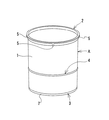
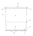
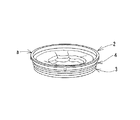
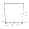
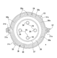
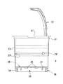
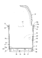
まず本発明の実施例1について図1〜11を参照しながら詳しく説明する。
aは、軟質プラスチック製で柔軟性を有する粘稠液収納用容器である。
すなわち、この粘稠液収納用容器aは、たとえばポリエチレン,ポリプロピレン、アルミニウム箔,ポリエステル、ナイロン等のプラスチックラミネートフィルムで形成され、かつ、上面開口側から底面開口側に向かって径細にした筒状本体1の上面開口周縁にプラスチック製の口縁環状枠2を固着して一体に成形するとともに、底面開口にプラスチック製の底板体3を嵌着し、かつ、該筒状本体1の外周面にプラスチック、金属、皮、布等からなり帯状にした少なくとも1個の胴部環状枠4を形成してなる。本粘稠液収納用容器の製造例では該筒状本体の高さの略中央部外周面にプラスチック製の1個の胴部環状枠を一体に成形して設けた。
First, a first embodiment of the present invention will be described in detail with reference to FIGS.
a is a flexible viscous liquid storage container made of soft plastic.
That is, the viscous liquid storage container a is formed of, for example, a plastic laminated film of polyethylene, polypropylene, aluminum foil, polyester, nylon, or the like, and has a cylindrical shape whose diameter decreases from the top opening side to the bottom opening side. A plastic rim
上記口縁環状枠2は、断面「 形の円環をなし、その円環の外周面に複数個の係入突起5……を所要の間隔たとえば90度間隔で突設形成している。
The edge
上記底板体3は、底板体円板6の外周に係入周壁7を、また、下面に複数個の係入突起8……を所要の配置で同じく一体成形している。
In the
この粘稠液収納用容器aは、所定の粘稠液を充填収納した後、上面開口を所定の蓋材(図示していない)で閉蓋し、段ボール箱等の包装用箱に収納された状態において、出荷輸送および保管に供されるものである。
しかし、その粘稠液を使用し終わって空になったときには、口縁環状枠2と底板体3を互いに接合または接近する方向に押し潰すことにより、折り畳まれた状態の筒状本体1,上記胴部環状枠4,口縁環状枠2および底板体3が重合し、その嵩を少なくとも数分の1に小さくして産業廃棄物を減容化できるものである(図3)。
This viscous liquid storage container a was filled with a predetermined viscous liquid and stored, then the upper surface opening was closed with a predetermined lid material (not shown), and stored in a packaging box such as a cardboard box. In the state, it is provided for shipping and storage.
However, when the viscous liquid has been used up and becomes empty, the annular
bは、硬質プラスチック製の粘稠液混練運搬用容器である。
この粘稠液混練運搬用容器bは、上面開口側から底面側に向かって僅かに径細にしかつ内面に大径部9′を有する胴壁9と底板10とが成形され、上記粘稠液収納用容器aを嵌挿する所要の大きさをなし、かつ、胴壁9の上面に口縁環状部11を成形するとともに、その口縁環状部11に提げ手12を回動自在に取り付けてなる。
b is a viscous liquid kneading and transporting container made of hard plastic.
The viscous liquid kneading / conveying container b has a
さらに、上記口縁環状部11には、粘稠液収納用容器aの上記複数個の係入突起5……を係入する複数個の係合凹処13……を所要の間隔で成形してある。
Further, a plurality of engaging
上記胴壁9と一体な底板10は上げ底になっているとともに、これら胴壁9の内面と底板10との間に、粘稠液収納用容器aの底板体3の上記係入周壁7を係入する内環溝14を形成し、かつ、その底板10には、粘稠液収納用容器aの複数個の係入突起8……を係入する複数個の係合孔15……を所要の配置で開設している。
The
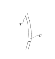
また、上記胴壁9は、底部至近位置であって、上記内環溝14に対向する部分の複数箇所に、上記内環溝14に係入した係入周壁7を挟持固定する押圧手段として、複数個の押圧片17……を形成している。本実施例では、その押圧片17を横長コ字形の切り込み線16で囲繞することにより、その肉厚を、胴壁9の該押圧片17以外の部分に比べ若干厚くし、外方から押すことにより、その内面を内環溝14内に僅かに偏倚させることができるように形成してある。
なお、上記押圧手段としては、本実施例の押圧片に限定されることなく、粘稠液収納用容器の底板外周の係入周壁を挟持固定する作用機能を有するものであれば他の構成のものでもよい。
In addition, the
The pressing means is not limited to the pressing piece of the present embodiment, but may be of any other configuration as long as it has a function of pinching and fixing the engaging peripheral wall of the outer periphery of the bottom plate of the viscous liquid storage container. It may be something.
上記構成の粘稠液収納用容器aは、所定の粘稠液を充填収納し閉蓋された状態で、段ボール箱等の包装用箱に収容梱包されて、出荷輸送および保管に供されるものであるが、一般に粘稠液の使用に際しては、その粘稠液収納用容器aを上記包装用箱から取り出し、上記構成の粘稠液混練運搬用容器bに嵌挿し、後記混練機cにより上記粘稠液の混練を予め行うことができる。 The viscous liquid storage container a having the above configuration is filled with a predetermined viscous liquid, and is packed in a packing box such as a cardboard box in a closed state, and is provided for shipping and transportation. However, in general, when using a viscous liquid, the container a for storing the viscous liquid is taken out of the packaging box, inserted into the container b for kneading and transporting the viscous liquid having the above configuration, and the kneading machine c described below is used. The kneading of the viscous liquid can be performed in advance.
その粘稠液収納用容器aの粘稠液混練運搬用容器bへの嵌挿は次のように行う。
すなわち、前者の口縁環状枠2を後者の口縁環状部11に乗載する状態にしながら、複数個の係入突起5……を複数個の係合凹処13……に一致係入させる。
これにより、前者の係入周壁7および複数個の係入突起8……が後者の内環溝14および複数個の係合孔15……にそれぞれほぼ緊密に係入し、前者の底板体3(円板6)が後者の底板10に重合するとともに、前者の胴部環状枠4が後者の大径部9′に対向位置する(図6)。
The insertion of the viscous liquid storage container a into the viscous liquid kneading / conveying container b is performed as follows.
That is, a plurality of
As a result, the former engagement peripheral wall 7 and the plurality of
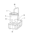
そして、粘稠液の混練を行うには、粘稠液収納用容器aを嵌挿した状態の上記粘稠液混練運搬用容器bを、たとえば、従来公知の混練機cの揺動台18に乗載して、複数個の締め付け手段により粘稠液混練運搬用容器の胴壁の少なくとも一部を締め付け、揺動台18に着脱自在に固定する。
たとえば、本発明の混練機cには、それに付属のチャック機構の複数個の締め付け片19……を備えており、粘稠液混練運搬用容器bの下半部を締め付け固定する(図11)。
ここでは、本発明の一実施例としてチャック機構の締め付け手段を例示したが、これに限定されることなく粘稠液収納用容器を嵌挿した粘稠液混練運搬用容器を締結固定できる締め付け手段であればよく、たとえばプラスチック製バンド、金属製押圧締結片、ゴム製バンド、皮製バンドなど着脱自在な締め付け手段を用いることができる。
この複数個の締め付け片19……は、粘稠液混練運搬用容器bの胴壁9の複数個の押圧片17……を内方に押圧し、その押圧片17が、上記のように、その内面を内環溝14内に僅かに偏倚させ、粘稠液収納用容器aの上記係入周壁7を内環溝14の内方壁面に押し付け挟持固定するものであって、特に粘稠液混練運搬用容器bの底部の外周に設けた少なくとも1個の押圧片17を締結押圧できるものである。
In order to knead the viscous liquid, the viscous liquid kneading / transporting container b with the viscous liquid accommodating container a inserted therein is, for example, placed on a rocking table 18 of a conventionally known kneading machine c. After being mounted, at least a part of the body wall of the container for kneading and transporting the viscous liquid is fastened by a plurality of fastening means and detachably fixed to the rocking table 18.
For example, the kneading machine c of the present invention is provided with a plurality of tightening
Here, the fastening means of the chuck mechanism is illustrated as an embodiment of the present invention, but the fastening means is not limited to this, and can fasten and fix the viscous liquid kneading / conveying container in which the viscous liquid storing container is inserted. Any removable fastening means such as a plastic band, a metal pressing fastener, a rubber band, and a leather band can be used.
The plurality of
粘稠液収納用容器aの上面開口を閉じていた蓋材は、該粘稠液収納用容器aを粘稠液混練運搬用容器bに嵌挿する際、または、嵌挿した後に取り外し、混練機cのパドル20を粘稠液収納用容器aにその上面開口を通じ嵌挿配置(セット)する。
The lid material, which closed the upper opening of the viscous liquid storage container a, is removed when the viscous liquid storage container a is inserted into the viscous liquid kneading / conveying container b or after being inserted and kneaded. The
そこで、混練機cを駆動すると、粘稠液収納用容器aと粘稠液混練運搬用容器bとが、一体的関係において揺動台18ごと左右に繰り返し往復回動し、パドル20に対し左右に揺動することにより粘稠液を混練することになる。
Then, when the kneading machine c is driven, the viscous liquid storage container a and the viscous liquid kneading / conveying container b are repeatedly reciprocated right and left with the rocking table 18 in an integrated relationship, and left and right with respect to the
粘稠液収納用容器aと粘稠液混練運搬用容器bとの上記一体的関係は、前者の口縁環状枠2の係入突起5……を後者の口縁環状部11の係合凹処13……に係入し、また、前者の底板体3の係入突起8……を後者の底板10の係合孔15……に係入していることによって保持されるものである。
The above-mentioned integral relationship between the viscous liquid storage container a and the viscous liquid kneading / conveying container b is based on the fact that the
粘稠液収納用容器aと粘稠液混練運搬用容器bとがパドル20との関係でする上記揺動にともなって、粘稠液収納用容器aが、軟質プラスチック製で柔軟性を有することに起因すると見られる筒状本体1の捻れや窄まり現象は、上記一体的関係の保持の他に、該筒状本体1の略中央部外周面に一体に成形した胴部環状枠4によっても阻止される。
The viscous liquid storage container a is made of soft plastic and has flexibility due to the above-mentioned swinging movement of the viscous liquid storage container a and the viscous liquid kneading / conveying container b in relation to the
さらに、上記揺動にともない上記と同じ原因により生じると見られる粘稠液収納用容器a(筒状本体1)の下半部の浮き上がりは、混練機cのチャック機構の締め付け片19……により、粘稠液混練運搬用容器bの下半部を締め付け固定することによって、粘稠液混練運搬用容器bの胴壁9の押圧片17……が、粘稠液収納用容器aの係入周壁7を内環溝14の壁面に押し付けて挟持固定することによって阻止される。
Further, the lifting of the lower half of the viscous liquid storage container a (the cylindrical main body 1), which is considered to be caused by the same cause as the above due to the rocking, is caused by the
なお、粘稠液収納用容器a(筒状本体1)の下半部の浮き上がりの阻止には、上記締め付け固定の他、粘稠液収納用容器aの底板体3の係入突起8……が粘稠液混練運搬用容器bの底板10の係合孔15……に係入していることによる抵抗も寄与すると認められる。
In addition, in order to prevent the lower half of the viscous liquid container a (cylindrical main body 1) from being lifted, in addition to the above-mentioned tightening and fixing, the engaging
次に、本発明の実施例2について図12〜27を参照しながら詳しく説明する。
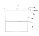
dは、軟質プラスチック製で柔軟性を有する粘稠液収納用容器である。この粘稠液収納用容器dは、所要のプラスチックラミネートフィルムで形成され、かつ、上面開口側から底面開口側に向かってやや径細にした筒状本体21の上面開口周縁にプラスチック製の口縁環状枠22を固着して一体に成形するとともに、底面開口にプラスチック製の底板体23を嵌着し、かつ、該筒状本体21の外周面にプラスチック、金属、皮、布等からなり帯状にした少なくとも1個の胴部環状枠24を形成してなる。本粘稠液収納用容器の製造例では該筒状本体の高さの略中央部外周面にプラスチック製の1個の胴部環状枠を一体に成形して設けた。
Next, a second embodiment of the present invention will be described in detail with reference to FIGS.
d is a flexible viscous liquid storage container made of soft plastic. The viscous liquid storage container d is formed of a required plastic laminate film, and has a plastic lip formed on the periphery of the upper surface opening of the cylindrical
上記のように、この粘稠液収納用容器dは、概括的には実施例1の粘稠液収納用容器aと共通の構成を有するものであるが、上記口縁環状枠22および底板体23が粘稠液収納用容器aのものと相違しており、それらは以下のようなものである。 As described above, the viscous liquid storage container d generally has the same configuration as the viscous liquid storage container a of the first embodiment. 23 is different from that of the viscous liquid storage container a, and they are as follows.
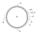
上記口縁環状枠22は、鍔部22aの内周縁に上側リブ22bおよび下側リブ22cを連設した断面ト形の円環をなしており、その上側リブ22bおよび下側リブ22cの内面を上記筒状本体21に固着している。
上記鍔部22aの互いに対向する位置には一対の取っ手22′,22′が突出形成されている。また、上記下側リブ22cの外周面には複数個の係入突起25を所要の間隔で、たとえば180度間隔で突設形成している。
The edge
A pair of
また、上記底板体23は、底板体円板26の外周下方に係入周壁27を形成し、底板体円板26の下面に筒状の複数個の係入突起28……を所要の配置で一体成形している。さらに、底板体円板26の外周上方には上記係入周壁27と同径の上側リブ27′を連続形成している。この上側リブ27′があることによって、該底板体23は実施例1の底板体3よりも強度を高め、かつ筒状本体21との接着を強固にし、該接着部分が損傷破損するのを防止したものとなっている。
Further, the
この粘稠液収納用容器dは、所定の粘稠液を充填収納した後、上記口縁環状枠22の上側リブ22bの上端面にアルミラミネートフィルム等からなる所要の蓋材22dを貼着することによって、上面開口を閉蓋し、かつ、段ボール箱等の包装用箱に収納された状態において、出荷輸送および保管に供されるものである。
上記蓋材22dは、上面開口よりも充分に大きく、たとえば平面方形に形成されたもので、上記上側リブ22bの外方へ延出する延出部22eを有しているので(図16参照)、開封時には、その延出部22eをつまんで引き剥がすことができるようになっている。
After the viscous liquid storage container d is filled with a predetermined viscous liquid, a required
The
また、口縁環状枠22は、内面に筒状本体21の上端を固着している上記上側リブ22bの部分をヘラかすり用リブとして用いることができ、粘稠液を取り出すのに用いるヘラに付いた余分な粘稠液を取り除くのに役立つものである。
In addition, the edge
その粘稠液を使用し終わって空になったときには、口縁環状枠22と底板体23を互いに接合または接近する方向に押し潰すことにより、折り畳まれた状態の筒状本体21,上記胴部環状枠24,口縁環状枠22および底板体23が重合し、その嵩を少なくとも数分の1に小さくして産業廃棄物を減容化できるものである(図示していない)。
When the viscous liquid is emptied after use, the annular
eは、硬質プラスチック製の粘稠液混練運搬用容器である。
この粘稠液混練運搬用容器eは、外周面に段差を設けて上面開口側よりも底面側を径細にするとともに、高さ方向略中央部の内面に大径部29′を有する胴壁29と底板30とが成形され、かつ、上記粘稠液収納用容器dを嵌挿する所要の大きさをなしている。
上記胴壁29の大径部29′の互いに対向する位置には窓孔29″,29″を開設してあり、また、径細にした上記段差よりも底面側の外周面に多数の縦筋を成形して、外周を凹凸波状にしている。
また、上記胴壁29の上面には口縁環状部31を成形し、その口縁環状部31の互いに対向する位置には提げ手取付部31a,31aを突出形成し、そこに、提げ手32を回動自在に取り付けている。
"e" is a viscous liquid kneading and transporting container made of hard plastic.
This viscous liquid kneading / conveying container e has a step on the outer peripheral surface to make the bottom side smaller in diameter than the upper surface opening side, and has a large-
Window holes 29 "and 29" are opened at positions facing each other on the large diameter portion 29 'of the
Further, an
31bは、上記提げ手取付部31aに形成した突片で、上記提げ手32は、この突片31bに立て掛けることにより起立状態に保持できるようになっている。
32a,32aは、上記提げ手32の中央の直状部分に所要の間隔をおいて突出形成した一対の袋体吊下用突起である。この袋体吊下用突起32a,32aは、提げ手32を起立状態に保持して、硬化剤,トナー等の所要の混練用材料を収納した袋体等の容器を吊しておくのに使用するもので、その吊した容器の下端を開封することにより、混練用材料を、該粘稠液混練運搬用容器e内に嵌挿した粘稠液収納用容器d内の粘稠液に落流添加する。
さらに、上記口縁環状部31の互いに対向する位置に形成された幅広部31c,31cには、粘稠液収納用容器dの上記係入突起25,25を係入する複数個の係合凹処33,33を成形してあり、また、該口縁環状部31の、粘稠液収納用容器dの上記取っ手22′,22′に対応することとなる位置に、上縁側に開口させた切欠き部31′,31′を形成している。
Further, a plurality of engaging recesses for engaging the engaging
上記胴壁29と一体な底板30は上げ底になっているとともに、これら胴壁29の内面と底板30との間に、粘稠液収納用容器dの底板体23の上記係入周壁27を係入する内環溝34を形成し、かつ、その底板30には、粘稠液収納用容器dの複数個の係入突起28……を係入する複数個の係合孔35……を所要の配置で開設している。
The
36……は、底板30の下面側であって、上記係合孔35……の開口縁部に形成した係合孔補強壁、37は、同じく底板30の下面側であって、その係合孔35……の外側に形成した底板補強用環状壁である。
38は、底板30の下面側であって上記底板補強用環状壁37の外側に形成されている環状の台座である。それは二重の環状壁を複数の補強リブ38a…で連結してなるもので、上記底板補強用環状壁37よりも高さを高くしている。39,39は、その台座38の二重壁を貫通させて開設した通気孔である。
36 is an underside of the
上記構成の粘稠液混練運搬用容器eは、外周面に段差を設けたことにより、その段差より下面側の外径が、上面開口側の内径よりも小径になっており、複数の粘稠液混練運搬用容器eを互いに重合させる際には、上側の粘稠液混練運搬用容器eの胴壁29の下半部分を下側の同容器e内に嵌挿し、その段差部が下側の粘稠液混練運搬用容器eの胴壁29の口縁環状部31に乗載する状態にして積み上げておくことができるようにしてある(図23)。
また、台座38を二重壁からなるものとし、係合孔35……の開口縁部に係合孔補強壁36…を形成しているので、底板30周辺の強度が高いものになっている。
In the viscous liquid kneading and transporting container e having the above-described configuration, the outer diameter on the lower surface side is smaller than the inner diameter on the upper surface opening side due to the provision of a step on the outer peripheral surface. When the liquid kneading / conveying containers e are polymerized with each other, the lower half of the
In addition, the
また、上記構成の粘稠液収納用容器dは、所定の粘稠液を充填収納し閉蓋された状態で、段ボール箱等の包装用箱に収容梱包されて、出荷輸送および保管に供されるものであるが、一般に粘稠液の使用に際しては、その粘稠液収納用容器dを上記包装用箱から取り出し、上記構成の粘稠液混練運搬用容器eに嵌挿し、混練機により上記粘稠液の混練を行うことができる。 In addition, the viscous liquid storage container d having the above configuration is filled and stored with a predetermined viscous liquid, and in a closed state, is housed and packed in a packaging box such as a cardboard box, and provided for shipping and transportation and storage. In general, when a viscous liquid is used, the viscous liquid storage container d is taken out of the packaging box, inserted into the viscous liquid kneading / transporting container e having the above-described configuration, and the kneading machine is used. Kneading of the viscous liquid can be performed.
その粘稠液収納用容器dの粘稠液混練運搬用容器eへの嵌挿は次のように行う。
すなわち、前者の口縁環状枠22を後者の口縁環状部31に乗載する状態にしながら、係入突起25,25を係合凹処33,33に一致係入させる(図26)。
The insertion of the viscous liquid storage container d into the viscous liquid kneading / conveying container e is performed as follows.
That is, the engaging
これにより、前者の係入周壁27および複数個の係入突起28……が後者の内環溝34および複数個の係合孔35……にそれぞれほぼ緊密に係入し、前者の底板体23(円板26)が後者の底板30に重合する。
また、前者の取っ手22′,22′が、後者の切欠き部31′,31′上に位置する(図27)。
さらに、前者の胴部環状枠24が後者の大径部29′に対向位置する(図25)ので、窓孔29″を通じて該胴部環状枠24が見えているのを確認することにより、その粘稠液収納用容器dが正しく嵌挿されていることを知ることができる。
なお、粘稠液収納用容器dを嵌挿する際には、底板30の上記係合孔35……および台座38の通気孔39,39を通じて、該粘稠液混練運搬用容器e内の空気が排出されるから、その嵌挿をスムーズに行うことができる。
As a result, the former engaging
Also, the former handles 22 ', 22' are located on the latter notches 31 ', 31' (FIG. 27).
Further, since the former torso
When the viscous liquid storage container d is inserted and inserted, the air in the viscous liquid kneading / conveying container e is passed through the engagement holes 35 of the
そして、粘稠液の混練を行う際には、粘稠液収納用容器dを嵌挿した状態の上記粘稠液混練運搬用容器eを、上記実施例1の場合にしたのと同様に、たとえば、図11に示した従来公知の混練機cの揺動台18に乗載して、複数個の締め付け手段19により粘稠液混練運搬用容器の胴壁の少なくとも一部を締め付け、揺動台18に着脱自在に固定する。
なお、締め付け手段19としては、粘稠液収納用容器を嵌挿した粘稠液混練運搬用容器を締結固定できるものであればよく、たとえばプラスチック製バンド、金属製押圧締結片、ゴム製バンド、皮製バンドなど着脱自在な締め付け手段を用いることができるのも、上記実施例1の場合と同様である。
When kneading the viscous liquid, the viscous liquid kneading / transporting container e in which the viscous liquid storage container d is inserted is inserted in the same manner as in the case of Example 1 above. For example, it is mounted on a rocking table 18 of a conventionally known kneading machine c shown in FIG. 11, and a plurality of tightening means 19 tighten at least a part of a body wall of the container for kneading and transporting the viscous liquid, and rocking. It is detachably fixed to the table 18.
The fastening means 19 may be any as long as it can fasten and fix a viscous liquid kneading / conveying container in which a viscous liquid storage container is inserted. For example, a plastic band, a metal pressing fastener, a rubber band, A removable fastening means such as a leather band can be used as in the case of the first embodiment.
粘稠液収納用容器dの上面開口を閉じていた蓋材は、該粘稠液収納用容器dを粘稠液混練運搬用容器eに嵌挿する際、または、嵌挿した後に取り外し、混練機cのパドル20を粘稠液収納用容器dにその上面開口を通じ嵌挿配置(セット)する。
The lid material, which closed the top opening of the viscous liquid storage container d, is removed when the viscous liquid storage container d is inserted into the viscous liquid kneading / conveying container e or after the viscous liquid storage container d is inserted and kneaded. The
そこで、混練機cを駆動すると、粘稠液収納用容器dと粘稠液混練運搬用容器eとが、一体的関係において揺動台18ごと左右に繰り返し往復回動し、パドル20に対し左右に揺動することにより粘稠液を混練することになる。 Then, when the kneading machine c is driven, the viscous liquid storage container d and the viscous liquid kneading / conveying container e repeatedly reciprocate left and right with the swing table 18 in an integrated relationship, The viscous liquid is kneaded by rocking.
粘稠液収納用容器dと粘稠液混練運搬用容器eとの上記一体的関係は、前者の口縁環状枠22の係入突起25,25を後者の口縁環状部31の係合凹処33,33に係入し、また、前者の底板体23の係入突起28……を後者の底板30の係合孔35……に係入していることによって保持されるものである。
The integral relationship between the viscous liquid storage container d and the viscous liquid kneading / conveying container e is such that the
混練の際の粘稠液収納用容器dの筒状本体21の捻れや窄まり現象は、上記一体的関係の保持の他に該筒状本体21の略中央部外周面に一体に成形した胴部環状枠24により阻止される。
The phenomenon of twisting and narrowing of the
さらに、粘稠液収納用容器d(筒状本体21)の下半部の浮き上がりは、粘稠液収納用容器dの底板体23の係入突起28……が粘稠液混練運搬用容器eの底板30の係合孔35……に係入していることによる抵抗により抑えられると認められる。
Further, the lifting of the lower half of the viscous liquid storage container d (the cylindrical main body 21) is caused by the
粘稠液混練運搬用容器eに嵌挿された粘稠液収納用容器dの取っ手22′,22′は、粘稠液混練運搬用容器eの切欠き部31′,31′の上に位置しているので、使用後の該粘稠液収納用容器dの持ち上げ,取り外しは、切欠き部31′,31′から取っ手22′,22′の下面に指を添えて下方より持ち上げることにより容易に行うことができる。 The handles 22 ', 22' of the viscous liquid container d inserted into the viscous liquid kneading / conveying container e are positioned above the notches 31 ', 31' of the viscous liquid kneading / conveying container e. The viscous liquid storage container d after use can be easily lifted and removed by attaching the fingers to the lower surfaces of the handles 22 ', 22' from the notches 31 ', 31' and lifting the container d from below. Can be done.
a,d 粘稠液収納用容器
b,e 粘稠液混練運搬用容器
c 混練機
1,21 筒状本体
2,22 口縁環状枠
3,23 底板体
4,24 胴部環状枠
5,25 係入突起
7,27 係入周壁
8,28 係入突起
9,29 胴壁
10,30 底板
11,31 口縁環状部
12,32 提げ手
13,33 係合凹処
14,34 内環溝
15,35 係合孔
16 切り込み線
17 押圧片
18 揺動台
19 締め付け片
20 パドル
36 係合孔補強壁
37 底板補強用環状壁
38 台座
39 通気孔
a, d Viscous liquid storage container b, e Viscous liquid kneading / carrying
10,30 bottom plate
11, 31 Ring edge
12, 32
13, 33 engagement recess
14, 34 Inner ring groove
15, 35 Engagement hole
16 score line
17 Pressing piece
18 Rocking table
19 Tightening piece
20 paddles
36 Engagement hole reinforcement wall
37 Bottom plate reinforcing annular wall
38 pedestal
39 Vent
Claims (16)
Priority Applications (1)
| Application Number | Priority Date | Filing Date | Title |
|---|---|---|---|
| JP2003360553A JP4422460B2 (en) | 2003-01-31 | 2003-10-21 | Sealing material storage container, sealing material storage container and sealing material kneading and conveying container, and combination of both containers and kneading machine |
Applications Claiming Priority (2)
| Application Number | Priority Date | Filing Date | Title |
|---|---|---|---|
| JP2003024380 | 2003-01-31 | ||
| JP2003360553A JP4422460B2 (en) | 2003-01-31 | 2003-10-21 | Sealing material storage container, sealing material storage container and sealing material kneading and conveying container, and combination of both containers and kneading machine |
Publications (2)
| Publication Number | Publication Date |
|---|---|
| JP2004250102A true JP2004250102A (en) | 2004-09-09 |
| JP4422460B2 JP4422460B2 (en) | 2010-02-24 |
Family
ID=33032286
Family Applications (1)
| Application Number | Title | Priority Date | Filing Date |
|---|---|---|---|
| JP2003360553A Expired - Fee Related JP4422460B2 (en) | 2003-01-31 | 2003-10-21 | Sealing material storage container, sealing material storage container and sealing material kneading and conveying container, and combination of both containers and kneading machine |
Country Status (1)
| Country | Link |
|---|---|
| JP (1) | JP4422460B2 (en) |
Cited By (3)
| Publication number | Priority date | Publication date | Assignee | Title |
|---|---|---|---|---|
| US7694841B2 (en) * | 2004-08-30 | 2010-04-13 | Sunstar Engineering Inc. | Holding container, external container for kneading and transportation, and kneading device |
| JP2020002795A (en) * | 2018-06-25 | 2020-01-09 | 株式会社ジャパンエンジンコーポレーション | Marine internal combustion engine |
| JP2020002794A (en) * | 2018-06-25 | 2020-01-09 | 株式会社ジャパンエンジンコーポレーション | Marine internal combustion engine |
-
2003
- 2003-10-21 JP JP2003360553A patent/JP4422460B2/en not_active Expired - Fee Related
Cited By (3)
| Publication number | Priority date | Publication date | Assignee | Title |
|---|---|---|---|---|
| US7694841B2 (en) * | 2004-08-30 | 2010-04-13 | Sunstar Engineering Inc. | Holding container, external container for kneading and transportation, and kneading device |
| JP2020002795A (en) * | 2018-06-25 | 2020-01-09 | 株式会社ジャパンエンジンコーポレーション | Marine internal combustion engine |
| JP2020002794A (en) * | 2018-06-25 | 2020-01-09 | 株式会社ジャパンエンジンコーポレーション | Marine internal combustion engine |
Also Published As
| Publication number | Publication date |
|---|---|
| JP4422460B2 (en) | 2010-02-24 |
Similar Documents
| Publication | Publication Date | Title |
|---|---|---|
| US4805799A (en) | Container with unitary bladder | |
| TWI308547B (en) | Consumables container with nested insert and manufacturing method thereof | |
| US6520335B2 (en) | Method and container for packaging multi-component polymer coatings and adhesives | |
| JP4609429B2 (en) | Combination container and kneader | |
| CN1950258A (en) | A device for filling and refilling flexible containers | |
| US5713510A (en) | Containers | |
| JP2004250102A (en) | Viscous liquid storage container, viscous liquid kneading and transporting container, combination of these two containers, combination of these two containers and kneading machine | |
| WO2003008275A2 (en) | Collapsible container | |
| JP2005239211A (en) | Two-component mixed packaging bag | |
| KR100849859B1 (en) | Storage container, external container for kneading and transporting the container, and kneader | |
| WO2005113377A1 (en) | Multi-compartment container | |
| US6003730A (en) | Hand holdable manually dispensing mastic container | |
| JP2001240035A (en) | Sealing material-housing container, sealing material- kneading and carrying container, and combination of those containers | |
| JPH08337288A (en) | Pallet with discharging function for container | |
| JP2006306462A (en) | Fluid material storing container fixing device | |
| JPH1111475A (en) | Container capable of being disassembled | |
| JP3137058U (en) | Packaging equipment | |
| JP2000142797A (en) | Container with inner bag for receiving liquid | |
| US11198545B2 (en) | System for packaging two components | |
| JP3028699U (en) | Two-component mixed adhesive container | |
| JP2004182323A (en) | Storage container, mixing-kneading transport container, and combination of these containers | |
| JP2605206B2 (en) | Parent and child can | |
| JP2001080681A (en) | Storage method and mixing container of reactive substance, mixing container of additive substance, auxiliary member used for the mixing container | |
| JP3260548B2 (en) | Mixing container and inner bag used for it | |
| JP2002249169A (en) | Self-standing resistant container, its supporting frame, packing material made of these and packing and kneading equipment |
Legal Events
| Date | Code | Title | Description |
|---|---|---|---|
| A711 | Notification of change in applicant |
Free format text: JAPANESE INTERMEDIATE CODE: A711 Effective date: 20050811 |
|
| RD02 | Notification of acceptance of power of attorney |
Free format text: JAPANESE INTERMEDIATE CODE: A7422 Effective date: 20050913 |
|
| A621 | Written request for application examination |
Free format text: JAPANESE INTERMEDIATE CODE: A621 Effective date: 20060725 |
|
| A521 | Written amendment |
Free format text: JAPANESE INTERMEDIATE CODE: A821 Effective date: 20080318 |
|
| RD02 | Notification of acceptance of power of attorney |
Free format text: JAPANESE INTERMEDIATE CODE: A7422 Effective date: 20080318 |
|
| RD04 | Notification of resignation of power of attorney |
Free format text: JAPANESE INTERMEDIATE CODE: A7424 Effective date: 20080325 |
|
| A977 | Report on retrieval |
Free format text: JAPANESE INTERMEDIATE CODE: A971007 Effective date: 20090114 |
|
| A131 | Notification of reasons for refusal |
Free format text: JAPANESE INTERMEDIATE CODE: A131 Effective date: 20090310 |
|
| A521 | Written amendment |
Free format text: JAPANESE INTERMEDIATE CODE: A523 Effective date: 20090511 |
|
| TRDD | Decision of grant or rejection written | ||
| A01 | Written decision to grant a patent or to grant a registration (utility model) |
Free format text: JAPANESE INTERMEDIATE CODE: A01 Effective date: 20091104 |
|
| A01 | Written decision to grant a patent or to grant a registration (utility model) |
Free format text: JAPANESE INTERMEDIATE CODE: A01 |
|
| A61 | First payment of annual fees (during grant procedure) |
Free format text: JAPANESE INTERMEDIATE CODE: A61 Effective date: 20091204 |
|
| FPAY | Renewal fee payment (event date is renewal date of database) |
Free format text: PAYMENT UNTIL: 20121211 Year of fee payment: 3 |
|
| R150 | Certificate of patent or registration of utility model |
Ref document number: 4422460 Country of ref document: JP Free format text: JAPANESE INTERMEDIATE CODE: R150 Free format text: JAPANESE INTERMEDIATE CODE: R150 |
|
| FPAY | Renewal fee payment (event date is renewal date of database) |
Free format text: PAYMENT UNTIL: 20131211 Year of fee payment: 4 |
|
| R250 | Receipt of annual fees |
Free format text: JAPANESE INTERMEDIATE CODE: R250 |
|
| R250 | Receipt of annual fees |
Free format text: JAPANESE INTERMEDIATE CODE: R250 |
|
| R250 | Receipt of annual fees |
Free format text: JAPANESE INTERMEDIATE CODE: R250 |
|
| R250 | Receipt of annual fees |
Free format text: JAPANESE INTERMEDIATE CODE: R250 |
|
| R250 | Receipt of annual fees |
Free format text: JAPANESE INTERMEDIATE CODE: R250 |
|
| R250 | Receipt of annual fees |
Free format text: JAPANESE INTERMEDIATE CODE: R250 |
|
| R250 | Receipt of annual fees |
Free format text: JAPANESE INTERMEDIATE CODE: R250 |
|
| R250 | Receipt of annual fees |
Free format text: JAPANESE INTERMEDIATE CODE: R250 |
|
| LAPS | Cancellation because of no payment of annual fees |