JP2004253111A - Optical pickup device - Google Patents
Optical pickup device Download PDFInfo
- Publication number
- JP2004253111A JP2004253111A JP2003399764A JP2003399764A JP2004253111A JP 2004253111 A JP2004253111 A JP 2004253111A JP 2003399764 A JP2003399764 A JP 2003399764A JP 2003399764 A JP2003399764 A JP 2003399764A JP 2004253111 A JP2004253111 A JP 2004253111A
- Authority
- JP
- Japan
- Prior art keywords
- light
- diffraction grating
- recording medium
- optical recording
- pickup device
- Prior art date
- Legal status (The legal status is an assumption and is not a legal conclusion. Google has not performed a legal analysis and makes no representation as to the accuracy of the status listed.)
- Pending
Links
Images


Classifications
-
- G—PHYSICS
- G11—INFORMATION STORAGE
- G11B—INFORMATION STORAGE BASED ON RELATIVE MOVEMENT BETWEEN RECORD CARRIER AND TRANSDUCER
- G11B7/00—Recording or reproducing by optical means, e.g. recording using a thermal beam of optical radiation by modifying optical properties or the physical structure, reproducing using an optical beam at lower power by sensing optical properties; Record carriers therefor
- G11B7/12—Heads, e.g. forming of the optical beam spot or modulation of the optical beam
- G11B7/135—Means for guiding the beam from the source to the record carrier or from the record carrier to the detector
- G11B7/1353—Diffractive elements, e.g. holograms or gratings
-
- G—PHYSICS
- G11—INFORMATION STORAGE
- G11B—INFORMATION STORAGE BASED ON RELATIVE MOVEMENT BETWEEN RECORD CARRIER AND TRANSDUCER
- G11B7/00—Recording or reproducing by optical means, e.g. recording using a thermal beam of optical radiation by modifying optical properties or the physical structure, reproducing using an optical beam at lower power by sensing optical properties; Record carriers therefor
- G11B7/12—Heads, e.g. forming of the optical beam spot or modulation of the optical beam
- G11B7/125—Optical beam sources therefor, e.g. laser control circuitry specially adapted for optical storage devices; Modulators, e.g. means for controlling the size or intensity of optical spots or optical traces
Landscapes
- Physics & Mathematics (AREA)
- Optics & Photonics (AREA)
- Optical Recording Or Reproduction (AREA)
- Optical Head (AREA)
- Moving Of The Head For Recording And Reproducing By Optical Means (AREA)
Abstract
【課題】 方位性を有する位相シフト回折格子の組立位置調整が極めて容易な光ピックアップ装置を提供する。
【解決手段】 光ピックアップ装置30は、光源33と、傾斜多分割型位相シフト回折格子8と、光源から放射される光を光記録媒体32に集光する対物レンズ35と、光記録媒体によって反射された反射光を分岐する光分岐素子36と、分岐された反射光を受光する受光素子38とを含む構成である。前記回折格子8は、矩形の透光性素材からなる基板39上に形成され、基板の少なくとも1辺と、回折格子8を線対称になるように形成する対称軸線である仮想直線とが、平行になるように切出し製作される。このことによって、目視可能な基板の一辺を案内指標として、光記録媒体32の半径方向に垂直になるように組立位置を調整することができるので、回折格子8の組立位置調整が極めて容易になる。
【選択図】 図1
PROBLEM TO BE SOLVED: To provide an optical pickup device in which it is extremely easy to adjust an assembling position of a phase shift diffraction grating having azimuth.
An optical pickup device includes a light source, a tilted multi-segment phase shift diffraction grating, an objective lens for condensing light emitted from the light source on an optical recording medium, and reflection by the optical recording medium. The configuration includes a light branching element 36 that branches the reflected light that has been branched, and a light receiving element 38 that receives the branched reflected light. The diffraction grating 8 is formed on a substrate 39 made of a rectangular light-transmitting material, and at least one side of the substrate and a virtual straight line which is an axis of symmetry that forms the diffraction grating 8 to be line-symmetrical are parallel to each other. It is cut out and manufactured. Thus, the assembling position can be adjusted to be perpendicular to the radial direction of the optical recording medium 32 using one side of the visible substrate as a guide index, so that the assembling position of the diffraction grating 8 can be extremely easily adjusted. .
[Selection diagram] Fig. 1
Description
本発明は、光によって光記録媒体に情報を記録および/または光記録媒体から情報を再生する光ピックアップ装置に関する。 The present invention relates to an optical pickup device that records information on an optical recording medium by light and / or reproduces information from the optical recording medium.
コンパクトディスク(略称CD)、デジタルバーサタイルディスク(略称DVD)およびミニディスク(略称MD)などの光ディスクが、オーディオビデオおよびコンピュータなどの多くの分野において光記録媒体として利用されている。前述のような光記録媒体に記録される情報量である記憶容量の増大要求に従って、光記録媒体に形成されるトラックの間隔であるトラックピッチの狭幅化とともに、光記録媒体の中心近くの内周まで情報記憶領域として利用されるに至っている。 Optical discs such as compact discs (abbreviated CD), digital versatile discs (abbreviated DVD) and minidiscs (abbreviated MD) are used as optical recording media in many fields such as audio video and computers. In accordance with the demand for increasing the storage capacity, which is the amount of information recorded on the optical recording medium, as described above, the track pitch, which is the interval between tracks formed on the optical recording medium, is reduced, and the area near the center of the optical recording medium is reduced. It has been used as an information storage area up to the circumference.
このような光記録媒体を用いる情報記録再生装置においては、光記録媒体の情報記録面に光スポットを集光し、光記録媒体に形成されるトラックに光スポットを追従させて情報の記録または再生を行う。トラックに光スポットを追従させる制御をトラッキング制御と呼び、トラッキング制御は、光記録媒体によって反射される光を受光素子によって検出し、受光素子による検出信号を光記録媒体上に光を集光する集光手段である対物レンズを駆動させるアクチュエータにフィードバックすることによって行われる。このアクチュエータの駆動をフィードバック制御するために用いられる信号をトラッキング誤差信号(略称TES)と呼び、TESとして用いられる信号生成方法の1つにディファレンシャル・プッシュ・プル(略称DPP)法がある(たとえば、特許文献1参照)。 In an information recording / reproducing apparatus using such an optical recording medium, a light spot is focused on an information recording surface of the optical recording medium, and the information is recorded or reproduced by causing the light spot to follow a track formed on the optical recording medium. I do. The control for causing the light spot to follow the track is called tracking control, and the tracking control detects light reflected by the optical recording medium by the light receiving element and collects the detection signal from the light receiving element on the optical recording medium. This is performed by feeding back to an actuator that drives an objective lens that is an optical unit. A signal used for feedback control of the driving of the actuator is called a tracking error signal (abbreviated as TES), and one of the signal generation methods used as the TES includes a differential push-pull (abbreviated as DPP) method (for example, Patent Document 1).
DPP法におけるトラッキング誤差検出方法は、光源から放射された光を、回折格子によって、零(0)次回折光、プラス(+)1次回折光およびマイナス(−)1次回折光の3つのビームに回折し、これら3つのビームスポット間隔が、トラックピッチの1/2の奇数倍になるように光記録媒体のトラック上に照射し、光記録媒体のトラック回折反射による各ビームのプッシュプル信号の差動をとるものである。DPP法では、対物レンズが、光記録媒体の半径方向にシフトした際に、各プッシュプル信号に発生するオフセットが、互いにキャンセルし合うことによって、TESにおけるオフセットを低減することができるので、安定したトラッキングサーボを得ることができる。 In the tracking error detection method in the DPP method, light emitted from a light source is diffracted by a diffraction grating into three beams of zero (0) order diffracted light, plus (+) first order diffracted light, and minus (-) first order diffracted light. Irradiation is performed on the track of the optical recording medium such that the interval between these three beam spots is an odd multiple of 1/2 of the track pitch, and the differential of the push-pull signal of each beam due to the track diffraction reflection of the optical recording medium is obtained. Take it. In the DPP method, when the objective lens shifts in the radial direction of the optical recording medium, the offset generated in each push-pull signal cancels each other, so that the offset in TES can be reduced. A tracking servo can be obtained.
しかしながら、特許文献1に開示されるDPP法には、以下のような問題がある。光記録媒体に照射される0次回折光と±1次回折光とのビームスポット間隔が、光記録媒体の半径方向で正確に1/2トラックピッチになるように配置される必要があるので、回折格子を光記録媒体のトラックに対して精度よく回転調整しなければならない。また対物レンズの移動軌跡が常に光記録媒体の半径上になければならないという構成上の制約がある。さらに、トラックピッチ等の仕様が異なる光記録媒体に対しては、ビームスポット間隔がトラックピッチの1/2という関係を満足することができず、所望のTESを得ることができなくなるので、仕様の異なる複数種類の光記録媒体に共用することができない。
However, the DPP method disclosed in
このような問題に対応する従来技術の一つとして、0次回折光と±1次回折光とのビームスポット配置のトラック間隔に対する依存性が小さく、オフセットの発生が小さいトラッキング誤差検出方法が提案されている(たとえば、特許文献2参照)。 As one of the prior arts to cope with such a problem, there has been proposed a tracking error detection method in which the beam spot arrangement of the 0th-order diffracted light and the ± 1st-order diffracted light has a small dependence on the track interval and the occurrence of an offset is small. (For example, see Patent Document 2).
図8は、従来技術の光ピックアップ装置に用いられる位相シフト回折格子1の構成を簡略化して示す平面図である。従来技術の光ピックアップ装置に用いられる位相シフト回折格子1は、光記録媒体のトラックの接線方向(以後、トラック(Y)方向と略称する)に平行な分割線2によって、光記録媒体の半径(X)方向に配列する2つの領域3a,3bに分割され、領域3aの周期構造に対する領域3bの周期構造の位相が180度異なるように構成される。
FIG. 8 is a plan view showing a simplified configuration of the phase
このように構成される位相シフト回折格子1に光源から放射された光4が入射するとき、位相シフト回折格子1によって回折される±1次回折光には、180度の位相差が発生する。0次回折光のビームをメインビーム、±1次回折光のビームをサブビームとすると、位相差の加わらないメインビームのプッシュプル信号と、前述のように180度の位相差の加わるサブビームのプッシュプル信号とは、位相が180度ずれた信号となる。したがって、サブビームをメインビームに対してトラックピッチの1/2ずらせて配置しなくてもDPP信号を検出することができる。
When the light 4 emitted from the light source is incident on the phase
このことによって、位相シフト回折格子1を備える光ピックアップ装置では、1つの光ピックアップによって、トラックピッチの異なる複数種類の光記録媒体への記録/再生に対応することが可能になる。
As a result, in the optical pickup device including the phase
しかしながら、特許文献2に開示される技術では、メインビームおよびサブビームのビームスポット配置のトラック間隔に対する依存性を小さくすることができるけれども、2つのサブビーム同志は、同一トラックに配置されるように位相シフト回折格子1を微調整しなければならないという問題がある。したがって、特許文献2に開示される技術では、回折格子の位置調整の簡略化を実現するには不充分である。
However, in the technique disclosed in
回折格子の位置調整の簡略化を実現する他の従来技術として、3つのビームすなわち0次回折光であるメインビームおよび±1次回折光であるサブビームを生成する回折格子に、部分的に格子溝と格子の山との周期構造を反転させた位相シフト回折格子を用いることが提案されている(たとえば、特許文献3参照)。 As another conventional technique for simplifying the position adjustment of the diffraction grating, a grating groove and a grating are partially provided in a diffraction grating that generates three beams, that is, a main beam that is a zero-order diffraction light and a sub-beam that is a ± first-order diffraction light. It has been proposed to use a phase shift diffraction grating in which the periodic structure of the peak is inverted (for example, see Patent Document 3).
図9は、他の従来技術の光ピックアップ装置に用いられる位相シフト回折格子5の構成を簡略化して示す平面図である。位相シフト回折格子5は、光記録媒体のトラック(Y)方向と半径(X)方向とを軸とするX−Y平面のたとえば第1象眼6のみが他の領域に比べて、周期構造の位相差が180度異なるように構成される。
FIG. 9 is a simplified plan view showing the configuration of a phase
位相シフト回折格子5によって、光源からの入射光7が回折されて生成される±1次回折光であるサブビームでは、第1象眼6の部分においてのみ180度の位相差が付加される。位相シフト回折格子5によって生成される第1象眼6のみに位相差の付加されたサブビームを用いたプッシュプル信号は、位相差が付加されないメインビームのプッシュプル信号に比べて振幅が小さくほぼ0になる。このように、トラックに対するサブビームの位置に関らずプッシュプル信号が検出されないので、サブビームをメインビームと同一のトラック上に配置しても、また異なるトラック上に配置してもほぼ同じ信号を得ることができる。したがって、メインビームとサブビームとの間隔およびサブビームの配置についても考慮する必要がなく、位相シフト回折格子5の回転位置調整を簡略化することができる。
A phase difference of 180 degrees is added only to the first inlaid
しかしながら、特許文献3に開示される技術には、以下の問題がある。光源、回折格子および集光手段である対物レンズの相対的な位置関係によっては、サブビームのプッシュプル信号のトラック変調成分が設計どおりにキャンセルされない場合がある。これは、回折格子を通過する有効光ビームにおける位相差の付加されない領域と位相差の付加される領域との利用割合が、設計値に対してずれを生じることによる。このずれを生じる原因には、装置の組立位置調整精度によるものと、動作時に対物レンズが光記録媒体の半径方向にシフトすることによるものとがある。 However, the technology disclosed in Patent Document 3 has the following problems. The track modulation component of the push-pull signal of the sub-beam may not be canceled as designed depending on the relative positional relationship between the light source, the diffraction grating, and the objective lens as the light condensing means. This is because the utilization ratio between the region where the phase difference is not added and the region where the phase difference is added in the effective light beam passing through the diffraction grating is different from the design value. There are two causes for this displacement: the one caused by the accuracy of the assembly position adjustment of the apparatus and the other caused by the shift of the objective lens in the radial direction of the optical recording medium during operation.
このような問題を解決するべく装置の組立位置調整精度の許容範囲を緩和する従来技術として、図10に示す傾斜多分割型位相シフト回折格子8と称される回折格子が提案されている(非特許文献1参照)。また図11は、図10に示す傾斜多分割型位相シフト回折格子8を備える従来の光ピックアップ装置9の構成を簡略化して示す斜視図である。
In order to solve such a problem, a diffraction grating called a tilted multi-division type phase
傾斜多分割型位相シフト回折格子8は、装着状態にある光記録媒体10の半径(X)方向に垂直な仮想直線11に関して線対称に形成され、かつ仮想直線11に対して傾斜角度θを有するように形成される複数の回折領域12に分割され、隣接する一方の回折領域12aと他方の回折領域12bとの格子周期が互いに180度の位相差を有する。
The inclined multi-division phase
図10(b)は、図10(a)に示す閉曲線で囲う領域A部の拡大図であり、各回折領域12は、図10(b)に示すように、図10(b)の黒塗り部13と図10(b)の白塗り部14とが、トラック(Y)方向に繰り返されることによって回折格子を構成している。隣接する回折領域12a,12bでは、配列ピッチが1/2だけずれて構成されるので、前述のように180度の位相差が生じる。
FIG. 10B is an enlarged view of an area A surrounded by the closed curve shown in FIG. 10A. Each
図11を参照して、従来の光ピックアップ装置9における信号検出動作について説明する。光源15から放射された光16は、傾斜多分割型位相シフト回折格子8によって、0次回折光であるメインビーム17と、±1次回折光である2つの第1および第2サブビーム18,19とに回折される。回折された光は、コリメートレンズ20によって略平行光にされ、対物レンズ21によって光記録媒体10に集光照射される。光記録媒体10によって反射された光は、再び対物レンズ21とコリメートレンズ20とを通過した後、ホログラム22によって分岐されて受光素子23に入射し、受光素子23によって受光検出される。
With reference to FIG. 11, a signal detection operation in the conventional
受光素子23は、光記録媒体10のトラック(Y)方向に平行な分割線によって分割されたホログラム22の2つの領域によってメインビーム17ならびに第1および第2サブビーム18,19を分岐した光をそれぞれ受光するように構成され、それぞれの差信号からプッシュプル信号を得る。
The
図12はサブビームが受光素子23によって受光されている状態を例示する図であり、図13は図12(c)の拡大図である。図12(b)および図12(c)は、たとえば第1サブビーム18が、受光素子23によって受光されているビームスポットを表す。第1サブビーム18のスポット内には、光記録媒体10のトラックを構成するランド部10aとグルーブ部10bとによって形成される凹凸によってそれぞれ回折された光のスポット18a,18bとの重畳部25,26が形成される。
FIG. 12 is a diagram illustrating a state in which the sub beam is received by the
傾斜多分割型位相シフト回折格子8によって、サブビームには、位相差の付加される領域と位相差の付加されない領域とが形成されるとともに、光記録媒体10のランド部10aおよびグルーブ10bにおける回折によって位相差が与えられるので、光の重畳部25と重畳部26とにおいては、位相差の付加された暗部27と位相差の付加されていない明部28とが、互いに反転して形成される。
The tilted multi-segment phase
図14は、メインビーム17、第1および第2サブビーム18,19によるプッシュプル信号を示す図である。図14には、傾斜多分割型位相シフト回折格子8によって得られるメインビーム17のプッシュプル信号(MPP)と、第1および第2サブビーム18,19のプッシュプル信号(SPP1,SPP2)を示す。前述のようにサブビームにおける光の重畳部25,26に形成される暗部27と明部28とが反転し、重畳部25と重畳部26との面積がほぼ等しくなるので、トラックの変調成分がキャンセルされる。したがって、図14に示すように、第1および第2サブビーム18,19のSPP1,SPP2のトラック変調成分は、メインビーム17のMPPのトラック変調成分に比べて極めて小さくなる。
FIG. 14 is a diagram showing a push-pull signal by the
このように、第1および第2サブビーム18,19をメインビーム17と異なるトラック上に配置しても、また同一のトラック上に配置しても、ほぼ同様にトラック変調成分の抑制されたSPP1,SPP2を得ることができる。すなわちサブビームのトラック上の位置に関らずトラック変調成分を小さくしたプッシュプル信号を得ることができるので、傾斜多分割型位相シフト回折格子8の回転位置調整が簡略化される。さらに傾斜多分割型位相シフト回折格子8によって、光の重畳部25,26に形成される明部28と暗部27とは小さい領域に区分されるので、トラック変調成分のキャンセルに対する回折格子の回転位置の及ぼす影響が、極めて小さくなり、装置の組立位置調整精度の許容範囲が拡大される。
As described above, even if the first and second sub-beams 18 and 19 are arranged on a different track from the
しかしながら、非特許文献1に開示される技術には、以下の問題がある。傾斜多分割型位相シフト回折格子8は、装置の組立位置調整を簡略化することができるけれども、多分割されている回折領域12は前述の仮想直線11に対して予め定められる傾斜角度θを有するように形成されるので、方位性を有している。したがって、装置の組立位置調整時に、傾斜多分割型位相シフト回折格子8上の仮想直線11の方向を、装着状態にある光記録媒体10の半径(X)方向に対して垂直なトラック(Y)方向に合わせるという微調整は必要である。傾斜多分割型位相シフト回折格子8の仮想直線11は、あくまでも仮想のものであり目視することができないので、傾斜多分割型位相シフト回折格子8を組立位置調整する際に、案内指標とすることができない。非特許文献1には、方位性を有する傾斜多分割型位相シフト回折格子8を、光記録媒体10のトラック(Y)方向に対して特定の方向に微調整するための技術は何ら開示されておらず、また示唆されてもいない。
However, the technology disclosed in
本発明の目的は、方位性を有する位相シフト回折格子の組立位置調整が極めて容易な光ピックアップ装置を提供することである。 SUMMARY OF THE INVENTION It is an object of the present invention to provide an optical pickup device in which the assembling position of a phase shift diffraction grating having azimuth can be easily adjusted.
本発明は、光によって光記録媒体に情報を記録および/または光記録媒体から情報を再生する光ピックアップ装置において、
光を放射する光源と、
光源から放射される光を回折する回折格子であって、装着状態にある前記光記録媒体の半径方向に垂直な仮想直線に関して線対称に形成され、かつ前記仮想直線に対して傾斜角度を有するように形成される複数の回折領域に分割され、隣接する回折領域同志の格子周期が互いに180度の位相差を有する回折格子と、
光源から放射される光を前記光記録媒体に集光する集光手段と、
前記光記録媒体によって反射された反射光を分岐する光分岐素子と、
光分岐素子によって分岐された前記反射光を受光する受光素子とを備え、
前記回折格子は、
矩形の透光性素材からなる基板上に形成されることを特徴とする光ピックアップ装置である。
The present invention relates to an optical pickup device that records information on an optical recording medium by light and / or reproduces information from the optical recording medium,
A light source that emits light,
A diffraction grating for diffracting light emitted from a light source, the diffraction grating being formed symmetrically with respect to a virtual straight line perpendicular to a radial direction of the optical recording medium in a mounted state, and having an inclination angle with respect to the virtual straight line. A diffraction grating divided into a plurality of diffraction regions formed in a plurality of adjacent diffraction regions, and having a phase difference of 180 degrees between adjacent diffraction regions,
Condensing means for condensing light emitted from a light source on the optical recording medium,
An optical branching element that branches light reflected by the optical recording medium,
A light receiving element for receiving the reflected light branched by the light branching element,
The diffraction grating includes:
An optical pickup device formed on a substrate made of a rectangular translucent material.
また本発明は、前記回折格子は、前記光源と前記光分岐素子との間に配置されることを特徴とする。 Further, in the invention, it is preferable that the diffraction grating is disposed between the light source and the light branching element.
また本発明は、前記回折格子が、前記基板の前記光源を臨む面に形成され、前記光分岐素子が、前記基板の前記集光手段を臨む面に形成されることを特徴とする。 Further, the invention is characterized in that the diffraction grating is formed on a surface of the substrate facing the light source, and the light branching element is formed on a surface of the substrate facing the light condensing unit.
また本発明は、前記光源は、前記回折格子と前記光分岐素子とが形成される基板と一体的に形成されることを特徴とする。 Further, the invention is characterized in that the light source is formed integrally with a substrate on which the diffraction grating and the light splitting element are formed.
また本発明は、前記光源は、
外形が略直方体形状を有し、光記録媒体の面に垂直な方向の寸法である厚みtよりも、光記録媒体の面に平行な方向の寸法である幅wが大きく(w>t)なるように形成されることを特徴とする。
Further, the present invention provides the light source,
The outer shape has a substantially rectangular parallelepiped shape, and a width w, which is a dimension in a direction parallel to the surface of the optical recording medium, is larger than a thickness t, which is a dimension in a direction perpendicular to the surface of the optical recording medium (w> t). It is characterized by being formed as follows.
また本発明は、光によって光記録媒体に情報を記録および/または光記録媒体から情報を再生する光ピックアップ装置において、
光を放射する光源と、
光源から放射される光を回折する回折格子であって、装着状態にある前記光記録媒体の半径方向に垂直な仮想直線に関して線対称に形成され、かつ前記仮想直線に対して傾斜角度を有するように形成される複数の回折領域に分割され、隣接する回折領域同志の格子周期が互いに180度の位相差を有する回折格子と、
光源から放射される光を前記光記録媒体に集光する集光手段と、
前記光記録媒体によって反射された反射光を分岐する光分岐素子と、
光分岐素子によって分岐された前記反射光を受光する受光素子とを備え、
前記回折格子は、
前記集光手段と一体的に形成されることを特徴とする光ピックアップ装置である。
The present invention also provides an optical pickup device for recording information on an optical recording medium by light and / or reproducing information from the optical recording medium,
A light source that emits light,
A diffraction grating for diffracting light emitted from a light source, the diffraction grating being formed symmetrically with respect to a virtual straight line perpendicular to a radial direction of the optical recording medium in a mounted state, and having an inclination angle with respect to the virtual straight line. A diffraction grating divided into a plurality of diffraction regions formed in a plurality of adjacent diffraction regions, and having a phase difference of 180 degrees between adjacent diffraction regions,
Condensing means for condensing light emitted from a light source on the optical recording medium,
An optical branching element that branches light reflected by the optical recording medium,
A light receiving element for receiving the reflected light branched by the light branching element,
The diffraction grating includes:
An optical pickup device formed integrally with the light condensing means.
本発明によれば、光ピックアップ装置は、光源から放射される光を回折する回折格子であって、装着状態にある光記録媒体の半径方向に垂直な仮想直線に関して線対称に形成され、かつ仮想直線に対して傾斜角度を有するように形成される複数の回折領域に分割され、隣接する回折領域同志の格子周期が互いに180度の位相差を有する傾斜多分割型位相シフト回折格子と称される回折格子を備え、その回折格子が、矩形の透光性素材からなる基板上に形成される。 According to the present invention, the optical pickup device is a diffraction grating that diffracts light emitted from a light source, is formed symmetrically with respect to a virtual straight line perpendicular to the radial direction of the optical recording medium in the mounted state, and It is divided into a plurality of diffraction regions formed so as to have an inclination angle with respect to a straight line, and the grating periods of adjacent diffraction regions are referred to as a tilted multi-division phase shift diffraction grating having a phase difference of 180 degrees from each other. A diffraction grating is provided, and the diffraction grating is formed on a substrate made of a rectangular transparent material.
方位性を有する傾斜多分割型位相シフト回折格子では、回折格子における前述の仮想直線が、装着状態にある光記録媒体の半径方向に垂直になるように位置調整されることが、光ピックアップ装置の動作にとって望ましい状態である。回折格子を透光性素材からなる矩形の基板上に形成するに際し、仮想直線を矩形の基板の少なくとも一辺に揃えるように製作しておき、前述の基板の一辺を、光記録媒体の半径方向に垂直になるように組立位置調整するという極めて容易な手法によって、光記録媒体の半径方向に対して回折格子を所望の位置に組立調整することが可能になる。 In the tilted multi-division phase shift diffraction grating having azimuth, the position of the virtual straight line in the diffraction grating is adjusted so as to be perpendicular to the radial direction of the optical recording medium in the mounted state. This is a desirable state for operation. When forming the diffraction grating on a rectangular substrate made of a translucent material, it is manufactured so that the virtual straight line is aligned with at least one side of the rectangular substrate, and one side of the substrate is placed in the radial direction of the optical recording medium. By a very easy method of adjusting the assembly position so as to be perpendicular, the diffraction grating can be adjusted to a desired position in the radial direction of the optical recording medium.
また本発明によれば、回折格子は、光源と光分岐素子との間に配置される。このように配置することによって、光記録媒体による反射光が回折格子を通過することがないので、反射光の回折による迷光に起因する不要信号の発生を防止できる。また複数の異なる波長の光源を搭載する場合、光源寄りに回折格子を配置することによって、個々の光源にそれぞれ適応する回折格子を設けることが可能になる。 According to the invention, the diffraction grating is arranged between the light source and the light branching element. With this arrangement, the reflected light from the optical recording medium does not pass through the diffraction grating, so that it is possible to prevent generation of unnecessary signals due to stray light due to diffraction of the reflected light. When a plurality of light sources having different wavelengths are mounted, by disposing the diffraction gratings near the light sources, it becomes possible to provide diffraction gratings adapted to the respective light sources.
また本発明によれば、回折格子が、基板の光源を臨む面に形成され、光分岐素子が、基板の集光手段を臨む面に形成される。このように、傾斜多分割型位相シフト回折格子と光分岐素子とが、基板に一体的に形成されることによって、部材点数を減少させることができるとともに、省かれた部材の装着空間を削減することができるので、装置の小型化に寄与することができる。 According to the invention, the diffraction grating is formed on the surface of the substrate facing the light source, and the light branching element is formed on the surface of the substrate facing the light condensing means. As described above, since the inclined multi-division type phase shift diffraction grating and the light splitting element are integrally formed on the substrate, the number of members can be reduced, and the space for mounting the omitted members can be reduced. Therefore, it is possible to contribute to downsizing of the device.
また本発明によれば、光源は、外形が略直方体形状を有し、光記録媒体の面に垂直な方向の寸法である厚みtよりも、光記録媒体の面に平行な方向の寸法である幅wが大きく(w>t)なるように形成され、また好ましくは回折格子と光分岐素子とが形成される基板と一体的に形成される。 According to the invention, the light source has a substantially rectangular parallelepiped outer shape, and has a dimension in a direction parallel to the surface of the optical recording medium, rather than a thickness t that is a dimension in a direction perpendicular to the surface of the optical recording medium. It is formed so that the width w becomes large (w> t), and is preferably formed integrally with the substrate on which the diffraction grating and the light splitting element are formed.
光源に半導体レーザを用い、また光分岐素子にホログラムを用いて、光源、回折格子、光分岐素子および基板が一体的に形成されるものは、ホログラムレーザと呼ばれる。このホログラムレーザの回折格子に、傾斜多分割型位相シフト回折格子を用いることによって、ホログラムレーザの回転調整の必要がなくなるので、回転調整機構が不要になり、装置の組立調整におけるホログラムレーザの回転調整工程を省略することができるとともに、ホログラムレーザの回転ずれによる信頼性劣化を防止することができる。また、ホログラムレーザの回転調整の必要がないので、ホログラムレーザの回転調整のために必要とされていた空間、いわゆる調整代を設けることが不要になり、この調整代を無くすことによって、光ピックアップ装置の薄型化が実現される。 A device in which a light source, a diffraction grating, a light branching element, and a substrate are integrally formed using a semiconductor laser as a light source and a hologram as a light branching element is called a hologram laser. By using a tilted multi-division type phase shift diffraction grating as the diffraction grating of the hologram laser, there is no need to adjust the rotation of the hologram laser. The step can be omitted, and the reliability can be prevented from deteriorating due to the rotational deviation of the hologram laser. In addition, since there is no need to adjust the rotation of the hologram laser, it is not necessary to provide a space required for adjusting the rotation of the hologram laser, that is, a so-called adjustment allowance. Is realized.
また本発明によれば、光ピックアップ装置は、傾斜多分割型位相シフト回折格子を備え、傾斜多分割型位相シフト回折格子は、集光手段であるたとえば対物レンズと一体的に形成される。傾斜多分割型位相シフト回折格子における仮想直線が、対物レンズのトラッキング方向に対して垂直な方向に一致するように、回折格子を対物レンズ上に設ける。回折格子の設けられた対物レンズを、光記録媒体の半径方向にトラッキング可能なように装着することによって、回折格子の仮想直線が、光記録媒体の半径方向に垂直になるように位置決めすることができる。このことによって、回折格子の組立位置調整が極めて容易になりかつ回折格子の組立位置調整工程を省略することができるとともに、回折格子を設けるための別部材を必要としないので、別部材の省略に伴う空間の削減によって、装置の小型化に寄与することができる。 Further, according to the invention, the optical pickup device includes the tilted multi-segmented phase shift diffraction grating, and the tilted multi-segmented phase shift diffraction grating is formed integrally with, for example, an objective lens which is a light collecting means. The diffraction grating is provided on the objective lens such that a virtual straight line in the tilted multi-division type phase shift diffraction grating coincides with a direction perpendicular to the tracking direction of the objective lens. By mounting the objective lens provided with the diffraction grating so as to be able to track in the radial direction of the optical recording medium, it is possible to position the virtual straight line of the diffraction grating so as to be perpendicular to the radial direction of the optical recording medium. it can. This makes it extremely easy to adjust the assembly position of the diffraction grating and can omit the assembly position adjustment step of the diffraction grating. Further, since another member for providing the diffraction grating is not required, the separate member can be omitted. The accompanying reduction in space can contribute to downsizing of the device.
図1は本発明の実施の一形態である光ピックアップ装置30の構成を簡略化して示す図であり、図2は図1に示す光ピックアップ装置30に備わる回折素子31の構成を簡略化して示す斜視図である。光ピックアップ装置30は、光によって光記録媒体32に情報を記録および/または光記録媒体32から情報を再生することに用いられる。
FIG. 1 is a diagram showing a simplified configuration of an
光ピックアップ装置30は、光を放射する光源33と、光源33から放射される光を略平行光にするコリメートレンズ34と、光源33から放射される光を回折する回折格子8と、光源33から放射される光を光記録媒体32に集光する集光手段である対物レンズ35と、光記録媒体32によって反射された反射光を分岐する光分岐素子36と、光分岐素子36によって分岐された光を後述の受光素子38へ集光させる集光レンズ37と、光分岐素子36によって分岐され集光レンズ37によって集光される反射光を受光する受光素子38とを備える。
光源33には、半導体レーザが好適に用いられる。
The
As the
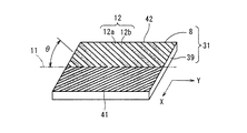
回折格子8は、矩形の透光性素材からなる基板39上に形成されることを特徴とする。回折格子8は、前述の傾斜多分割型位相シフト回折格子8であり、その構造および作用は前述のとおりであるので、説明を省略する。基板39は、透光性を有するたとえば石英ガラスまたはアクリル系樹脂などを素材として形成され、厳密には薄板状の直方体形状を有し、傾斜多分割型位相シフト回折格子8の形成される面の平面形状が矩形(本実施の形態では長方形)である。基板39と基板39に一体的に形成される傾斜多分割型位相シフト回折格子8とを合わせて、便宜上回折素子31と呼ぶ。回折素子31は、傾斜多分割型位相シフト回折格子8の形成される面を構成する長方形(矩形)の2つの長辺41,42が、仮想直線11に対して平行になるように、切出し製作される。傾斜多分割型位相シフト回折格子8の形成される回折素子31は、光源33と光分岐素子36との間に配置される。
The
光分岐素子36は、本実施の形態では偏光ビームスプリッタであり、光記録媒体32によって反射されたメインビーム43、第1および第2サブビーム44,45をそれぞれ反射して集光レンズ37に導く。受光素子38は、たとえばフォトダイオードによって構成される光電変換素子である。受光素子38は、メインビーム43を受光する受光部38aと、第1サブビーム44を受光する受光部38bと、第2サブビーム45を受光する受光部38cとを含む構成である。各受光部38a,38b,38cは、いずれも光記録媒体32のトラック(Y)方向に平行な分割線によって分割される2分割光検出器であり、各ビームのプッシュプル信号の差動をとることができる。
The
光ピックアップ装置30は、回折格子として傾斜多分割型位相シフト回折格子8を備えるので、前述と同様に、第1および第2サブビーム44,45のプッシュプル信号のトラック変調成分が、メインビーム43のプッシュプル信号のトラック変調成分に比べて極めて小さく、サブビームのトラック上の位置に関らずトラック変調成分の低減されたプッシュプル信号を得ることができる。したがって、傾斜多分割型位相シフト回折格子8の回転位置調整の簡略化を実現することができる。
Since the
また傾斜多分割型位相シフト回折格子8は、基板39上に形成され、回折素子31製作に際して、仮想直線11が基板39の2つの長辺41,42に対して平行になるように切出し製作される。傾斜多分割型位相シフト回折格子8は、方位性を有するので、仮想直線11が光記録媒体32の半径(X)方向に垂直なトラック(Y)方向に対して±3度以内になるように位置調整される必要がある。回折素子31は、仮想直線11と基板39の2つの長辺41,42とが平行になるように製作されるので、目視可能な基板39の長辺41,42を組立位置調整の案内指標とすることによって、基板の長辺41,42が光記録媒体32のトラック(Y)方向に対して平行になるように容易に装着することができる。このようにして、傾斜多分割型位相シフト回折格子8の仮想直線11が、光記録媒体32のトラック(Y)方向に対して±3度以内という望ましい位置に極めて容易に組立調整を行なうことが可能になる。
The tilted multi-segment phase
図3は、本発明の実施の第2形態である光ピックアップ装置50の構成を簡略化して示す図である。本実施の形態の光ピックアップ装置50は、実施の第1形態の光ピックアップ装置30に類似し、対応する部分については、同一の参照符号を付して説明を省略する。
FIG. 3 is a diagram showing a simplified configuration of an
光ピックアップ装置50において注目すべきは、光分岐素子53が、透光性素材からなる基板51上にホログラム52によって光分岐パターンの構成されることである。ここでは、光を分岐する機能を有する素子の総称に光分岐素子を用い、ホログラム52のように透光性基板51上に設けられるパターンによって光分岐機能を発現するものを光分岐パターンと呼ぶ。
What should be noted in the
ホログラム52によって反射光を光分岐する光分岐素子53は、実施の第1形態の光ピックアップ装置30における光分岐素子36である偏光ビームスプリッタに比べて寸法が小さいので、設置空間が小さくてすみ、装置の小型化に寄与することができる。
The
図4は、本発明の実施の第3形態である光ピックアップ装置55の構成を簡略化して示す図である。本実施の形態の光ピックアップ装置55は、実施の第2形態の光ピックアップ装置50に類似し、対応する部分については、同一の参照符号を付して説明を省略する。光ピックアップ装置55において注目すべきは、傾斜多分割型位相シフト回折格子8と、光分岐パターンを構成するホログラム52とが、透光性素材からなる基板56を共有することである。すなわち、傾斜多分割型位相シフト回折格子8が、基板56の光源33を臨む面57に形成され、ホログラム52が、基板56の対物レンズ35(直近ではコリメートレンズ34)を臨む面58に形成される。
FIG. 4 is a diagram showing a simplified configuration of an
このように、傾斜多分割型位相シフト回折格子8とホログラム52とを、基板56の対向する両面に一体的に形成することによって、2つの部材を1つに集約することができる。したがって、部材点数が削減され、装置が小型化される。
In this way, by forming the tilted multi-segment phase
図5は、本発明の実施の第4形態である光ピックアップ装置60の構成を簡略化して示す図である。本実施の形態の光ピックアップ装置60は、実施の第3形態の光ピックアップ装置55に類似し、対応する部分については、同一の参照符号を付して説明を省略する。
FIG. 5 is a diagram schematically illustrating a configuration of an
光ピックアップ装置60において注目すべきは、光源33が、傾斜多分割型位相シフト回折格子8とホログラム52とが形成される基板56と一体的に形成され、さらに受光素子38を内包することである。このように、光源33、傾斜多分割型位相シフト回折格子8、ホログラム52および受光素子38を一体化させた、いわゆるホログラムレーザ61を構成することによって、部材がさらに集約されるので、さらなる装置の小型化を実現することができる。
It should be noted that in the
図6は、本発明の実施の第5形態である光ピックアップ装置65の構成を簡略化して示す斜視図である。本実施の形態の光ピックアップ装置65は、実施の第4形態の光ピックアップ装置60に類似し、対応する部分については、同一の参照符号を付して説明を省略する。
FIG. 6 is a simplified perspective view showing a configuration of an
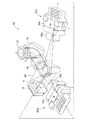
光ピックアップ装置65は、2つのホログラムレーザ61a,61bを備え、波長の異なる2種類の光を用いて、仕様の異なる2種類の光記録媒体に対して情報の記録/再生をすることができるように構成される。光ピックアップ装置65においては、ホログラムレーザ61a,61bに含まれる光源33a,33bが、半導体レーザであり、外形が略直方体形状に形成される。光源33a,33bは、不図示の装着状態にある光記録媒体の面に垂直な方向の寸法である厚みtよりも、光記録媒体の面に平行な方向の寸法である幅wが大きく(w>t)なるように形成されることを特徴とする。なお、ホログラムレーザ61a,61bに備わる基板56a,56bには、ホログラム52と傾斜多分割型位相シフト回折格子8とが一体的に形成されているけれども、図6では繁雑化を避けるために図示を省略した。
The
ホログラムレーザ61a,61bは、傾斜多分割型位相シフト回折格子8を備えるので、回転位置調整が不要であり、また前述のように傾斜多分割型位相シフト回折格子8の仮想直線11が基板56a,56bの辺に対して平行になるように製作しておくことによって、組立位置調整における位置決めも容易に行うことができる。したがって、ホログラムレーザ61a,61bを、ホログラムレーザ61a,61bから出射される光の軸まわりに回転調整するための空間である回転調整代を設ける必要がなくなる。このことによって、ホログラムレーザ61a,61bの厚みtを小さくすることが、直接装置の厚みを薄くすることにつながるので、装置の薄型化を実現することが可能になる。
Since the
以下図6を参照して光ピックアップ装置65の信号検出動作を説明する。ホログラムレーザ61aから出射された光は、光分岐素子69を透過し、コリメートレンズ34によって略平行光にされ、立上げミラー70によって光路を約90度曲げられて、対物レンズ35に入射する。対物レンズ35によって図示しない光記録媒体に集光照射された光は、光記録媒体によって反射され、再び対物レンズ35を透過し、立上げミラー70で光路を曲げられ、コリメートレンズ34および光分岐素子69を透過し、ホログラムレーザ61aに入射する。ホログラムレーザ61aに入射した光は、ホログラムによって分岐され、光源33aに内包される受光素子によって受光される。
Hereinafter, the signal detection operation of the
もう一つのホログラムレーザ61bから出射した光は、光分岐素子69によって反射されてコリメートレンズ34に導かれ、コリメートレンズ34に入射した光は略平行光にされ、立上げミラー70によって光路を約90度曲げられて、対物レンズ35に入射する。対物レンズ35によって光記録媒体に集光照射された光は、光記録媒体によって反射され、再び対物レンズ35を透過し、立上げミラー70で光路を曲げられ、コリメートレンズ34を透過した後、光分岐素子69によって反射されてホログラムレーザ61bに入射する。ホログラムレーザ61bに入射した光は、ホログラムによって分岐され、光源33bに内包される受光素子によって受光される。
The light emitted from the
このように、光ピックアップ装置65では、光の波長に応じて透過および反射して光を分岐する光分岐素子69を備えることによって、2つのホログラムレーザ61a,61bからそれぞれ出射される異なる波長の光を、光記録媒体に導き、光記録媒体からの反射光を受光検出することを可能にしている。
As described above, the
なおホログラムレーザ61aから出射した光の一部は、光分岐素子69によって反射し、ホログラムレーザ61bから出射した光の一部は、光分岐素子69を透過し、反射および透過した光は、それぞれ集光レンズ71によって自動出力制御ユニット72(略称APC)に入射される。APC72は、受光した光量に応じた制御信号を、光源33a,33bにそれぞれフィードバックし、光源33a,33bから放射される光の出力を安定化させる制御を行なう。
A part of the light emitted from the
図7は、本発明の実施の第6形態である光ピックアップ装置75の構成を簡略化して示す図である。本実施の形態の光ピックアップ装置75は、実施の第1形態の光ピックアップ装置30に類似し、対応する部分については同一の参照符号を付して説明を省略する。
FIG. 7 is a diagram schematically illustrating a configuration of an
光ピックアップ装置75において注目すべきは、傾斜多分割型位相シフト回折格子8が、対物レンズ35と一体的に形成されることである。傾斜多分割型位相シフト回折格子8における仮想直線11が、対物レンズ35のトラッキング方向に対して垂直な方向に一致するように、傾斜多分割型位相シフト回折格子8を対物レンズ35上に設け、傾斜多分割型位相シフト回折格子8の設けられた対物レンズ35を、光記録媒体32の半径方向にトラッキング可能なように装着することによって、傾斜多分割型位相シフト回折格子8の仮想直線11が、光記録媒体32の半径方向に垂直になるように位置決めすることができる。
What should be noted in the
このことによって、傾斜多分割型位相シフト回折格子8の組立位置調整が極めて容易になり、かつ傾斜多分割型位相シフト回折格子8の組立位置調整工程を省略することができるとともに、傾斜多分割型位相シフト回折格子8を設けるための別部材を必要としないので、別部材の省略に伴う空間の削減によって、装置の小型化に寄与することができる。
This makes it extremely easy to adjust the assembling position of the tilted multi-segmented phase
8 傾斜多分割型位相シフト回折格子
30,50,55,60,65,75 光ピックアップ装置
32 光記録媒体
33 光源
34 コリメートレンズ
35 対物レンズ
36,53,69 光分岐素子
37 集光レンズ
38 受光素子
39,51,56 基板
52 ホログラム
61 ホログラムレーザ
Claims (6)
光を放射する光源と、
光源から放射される光を回折する回折格子であって、装着状態にある前記光記録媒体の半径方向に垂直な仮想直線に関して線対称に形成され、かつ前記仮想直線に対して傾斜角度を有するように形成される複数の回折領域に分割され、隣接する回折領域同志の格子周期が互いに180度の位相差を有する回折格子と、
光源から放射される光を前記光記録媒体に集光する集光手段と、
前記光記録媒体によって反射された反射光を分岐する光分岐素子と、
光分岐素子によって分岐された前記反射光を受光する受光素子とを備え、
前記回折格子は、
矩形の透光性素材からなる基板上に形成されることを特徴とする光ピックアップ装置。 In an optical pickup device for recording information on an optical recording medium by light and / or reproducing information from the optical recording medium,
A light source that emits light,
A diffraction grating for diffracting light emitted from a light source, wherein the diffraction grating is formed to be line-symmetric with respect to a virtual straight line perpendicular to a radial direction of the optical recording medium in a mounted state, and has an inclination angle with respect to the virtual straight line. A diffraction grating divided into a plurality of diffraction regions formed in a plurality of adjacent diffraction regions, and having a phase difference of 180 degrees between adjacent diffraction regions,
Condensing means for condensing light emitted from a light source on the optical recording medium,
An optical branching element that branches light reflected by the optical recording medium,
A light receiving element for receiving the reflected light branched by the light branching element,
The diffraction grating includes:
An optical pickup device formed on a substrate made of a rectangular translucent material.
前記光源と前記光分岐素子との間に配置されることを特徴とする請求項1記載の光ピックアップ装置。 The diffraction grating includes:
2. The optical pickup device according to claim 1, wherein the optical pickup device is disposed between the light source and the light branching element.
前記光分岐素子が、前記基板の前記集光手段を臨む面に形成されることを特徴とする請求項1または2記載の光ピックアップ装置。 The diffraction grating is formed on a surface of the substrate facing the light source,
The optical pickup device according to claim 1, wherein the light branching element is formed on a surface of the substrate facing the light collecting unit.
前記回折格子と前記光分岐素子とが形成される基板と一体的に形成されることを特徴とする請求項3記載の光ピックアップ装置。 The light source is
The optical pickup device according to claim 3, wherein the optical pickup device is formed integrally with a substrate on which the diffraction grating and the light branching element are formed.
外形が略直方体形状を有し、光記録媒体の面に垂直な方向の寸法である厚みtよりも、光記録媒体の面に平行な方向の寸法である幅wが大きく(w>t)なるように形成されることを特徴とする請求項1〜4のいずれか1つに記載の光ピックアップ装置。 The light source is
The outer shape has a substantially rectangular parallelepiped shape, and the width w, which is the dimension in the direction parallel to the surface of the optical recording medium, is larger than the thickness t, which is the dimension in the direction perpendicular to the surface of the optical recording medium (w> t). The optical pickup device according to claim 1, wherein the optical pickup device is formed as described above.
光を放射する光源と、
光源から放射される光を回折する回折格子であって、装着状態にある前記光記録媒体の半径方向に垂直な仮想直線に関して線対称に形成され、かつ前記仮想直線に対して傾斜角度を有するように形成される複数の回折領域に分割され、隣接する回折領域同志の格子周期が互いに180度の位相差を有する回折格子と、
光源から放射される光を前記光記録媒体に集光する集光手段と、
前記光記録媒体によって反射された反射光を分岐する光分岐素子と、
光分岐素子によって分岐された前記反射光を受光する受光素子とを備え、
前記回折格子は、
前記集光手段と一体的に形成されることを特徴とする光ピックアップ装置。 In an optical pickup device for recording information on an optical recording medium by light and / or reproducing information from the optical recording medium,
A light source that emits light,
A diffraction grating for diffracting light emitted from a light source, wherein the diffraction grating is formed to be line-symmetric with respect to a virtual straight line perpendicular to a radial direction of the optical recording medium in a mounted state, and has an inclination angle with respect to the virtual straight line. A diffraction grating divided into a plurality of diffraction regions formed in a plurality of adjacent diffraction regions, and having a phase difference of 180 degrees between adjacent diffraction regions,
Condensing means for condensing light emitted from a light source on the optical recording medium,
An optical branching element that branches light reflected by the optical recording medium,
A light receiving element for receiving the reflected light branched by the light branching element,
The diffraction grating includes:
An optical pickup device formed integrally with the light condensing means.
Priority Applications (3)
| Application Number | Priority Date | Filing Date | Title |
|---|---|---|---|
| JP2003399764A JP2004253111A (en) | 2003-01-31 | 2003-11-28 | Optical pickup device |
| US10/769,567 US20040257960A1 (en) | 2003-01-31 | 2004-01-30 | Optical pick-up apparatus |
| CNB2004100284620A CN1267911C (en) | 2003-01-31 | 2004-01-31 | Optical pickup device |
Applications Claiming Priority (2)
| Application Number | Priority Date | Filing Date | Title |
|---|---|---|---|
| JP2003024188 | 2003-01-31 | ||
| JP2003399764A JP2004253111A (en) | 2003-01-31 | 2003-11-28 | Optical pickup device |
Publications (1)
| Publication Number | Publication Date |
|---|---|
| JP2004253111A true JP2004253111A (en) | 2004-09-09 |
Family
ID=33032282
Family Applications (1)
| Application Number | Title | Priority Date | Filing Date |
|---|---|---|---|
| JP2003399764A Pending JP2004253111A (en) | 2003-01-31 | 2003-11-28 | Optical pickup device |
Country Status (3)
| Country | Link |
|---|---|
| US (1) | US20040257960A1 (en) |
| JP (1) | JP2004253111A (en) |
| CN (1) | CN1267911C (en) |
Cited By (1)
| Publication number | Priority date | Publication date | Assignee | Title |
|---|---|---|---|---|
| US7593306B2 (en) | 2004-11-18 | 2009-09-22 | Samsung Electronics Co., Ltd. | Diffraction element and optical pick-up apparatus having the same |
Families Citing this family (6)
| Publication number | Priority date | Publication date | Assignee | Title |
|---|---|---|---|---|
| CN100541625C (en) * | 2005-01-20 | 2009-09-16 | 松下电器产业株式会社 | Optical pickup and optical disc device having same |
| JP2006228260A (en) * | 2005-02-15 | 2006-08-31 | Matsushita Electric Ind Co Ltd | Optical pickup |
| JP4180073B2 (en) * | 2005-07-28 | 2008-11-12 | シャープ株式会社 | Optical pickup device |
| KR20070070343A (en) * | 2005-12-29 | 2007-07-04 | 엘지전자 주식회사 | Optical pickup |
| JP2008027565A (en) * | 2006-06-21 | 2008-02-07 | Sharp Corp | Optical pickup |
| JP5142879B2 (en) * | 2008-08-06 | 2013-02-13 | 株式会社日立メディアエレクトロニクス | Optical pickup and optical disk apparatus |
Family Cites Families (14)
| Publication number | Priority date | Publication date | Assignee | Title |
|---|---|---|---|---|
| JPS6194246A (en) * | 1984-10-15 | 1986-05-13 | Sony Corp | Tracking error detection system |
| JPS61289448A (en) * | 1985-06-18 | 1986-12-19 | Mitsubishi Electric Corp | buffer storage device |
| JP3549301B2 (en) * | 1995-09-08 | 2004-08-04 | 三菱電機株式会社 | Optical head tracking error detector |
| US6765857B2 (en) * | 1996-09-03 | 2004-07-20 | Samsung Electronics Co., Ltd. | Optical recording and pickup head for digital versatile disc compatible with read-writable compact disc by adopting flat plate lens having staircase type diffraction grating structure |
| CN1122988C (en) * | 1997-08-12 | 2003-10-01 | 株式会社三协精机制作所 | Optical sensing head device |
| JP3385213B2 (en) * | 1998-05-29 | 2003-03-10 | ペンタックス株式会社 | Objective lens for optical head |
| JP2000132961A (en) * | 1998-10-23 | 2000-05-12 | Canon Inc | Magnetic thin film memory, reading method of magnetic thin film memory, and writing method of magnetic thin film memory |
| JP2000221388A (en) * | 1999-01-29 | 2000-08-11 | Fuji Photo Optical Co Ltd | Variable luminous flux size objective lens and optical device using it |
| JP4060007B2 (en) * | 1999-04-23 | 2008-03-12 | ペンタックス株式会社 | Optical system of optical disk device |
| JP2000311377A (en) * | 1999-04-28 | 2000-11-07 | Sharp Corp | Optical pickup device |
| EP1223575B1 (en) * | 1999-10-06 | 2008-05-07 | Matsushita Electric Industrial Co., Ltd. | Lens, optical head, optical information recording/reproducing apparatus, and optical information recording/recorded medium recording/reproducing method |
| JP4070941B2 (en) * | 2000-08-04 | 2008-04-02 | ペンタックス株式会社 | Objective lens for optical head |
| US6331943B1 (en) * | 2000-08-28 | 2001-12-18 | Motorola, Inc. | MTJ MRAM series-parallel architecture |
| JP4094501B2 (en) * | 2002-11-27 | 2008-06-04 | シャープ株式会社 | Optical pickup device |
-
2003
- 2003-11-28 JP JP2003399764A patent/JP2004253111A/en active Pending
-
2004
- 2004-01-30 US US10/769,567 patent/US20040257960A1/en not_active Abandoned
- 2004-01-31 CN CNB2004100284620A patent/CN1267911C/en not_active Expired - Fee Related
Cited By (1)
| Publication number | Priority date | Publication date | Assignee | Title |
|---|---|---|---|---|
| US7593306B2 (en) | 2004-11-18 | 2009-09-22 | Samsung Electronics Co., Ltd. | Diffraction element and optical pick-up apparatus having the same |
Also Published As
| Publication number | Publication date |
|---|---|
| US20040257960A1 (en) | 2004-12-23 |
| CN1267911C (en) | 2006-08-02 |
| CN1523586A (en) | 2004-08-25 |
Similar Documents
| Publication | Publication Date | Title |
|---|---|---|
| KR100424926B1 (en) | Optical pickup | |
| US6567355B2 (en) | Optical detector, optical pickup and optical information reproducing apparatus using optical pickup | |
| JP3384393B2 (en) | Optical head device, optical information recording / reproducing device, and radial tilt detection method | |
| JP3459777B2 (en) | Optical pickup device | |
| JP2004005892A (en) | Optical pickup | |
| CN100472623C (en) | Optical head device and optical disc device | |
| JP2004253111A (en) | Optical pickup device | |
| JP3836483B2 (en) | Optical integrated unit and optical pickup device including the same | |
| WO2004090878A1 (en) | Optical pickup | |
| JP3545307B2 (en) | Optical integrated unit, optical pickup device, and method of adjusting optical integrated unit | |
| CN100449621C (en) | Optical head device and optical disk device | |
| JP4083720B2 (en) | Optical pickup device | |
| JP2000011418A (en) | Hologram laser unit and optical pickup device using the same | |
| US20070041287A1 (en) | Optical pickup apparatus capable of detecting and compensating for spherical aberration caused by thickness variation of recording layer | |
| US5493425A (en) | Optical pickup apparatus having a quadrant hologram and a quadrant photo detector | |
| KR20020081437A (en) | Optical pickup and optical disc drive | |
| CN101866663A (en) | Optical integrated unit, adjusting method thereof, and optical pickup device | |
| JP3389416B2 (en) | Optical pickup device | |
| JP2638778B2 (en) | Optical head device | |
| JP2006309861A (en) | Optical integrated unit and optical pickup device | |
| JP4332693B2 (en) | Optical head, light emitting / receiving element, and optical recording medium recording / reproducing apparatus | |
| JP2001028145A (en) | Optical head device and disk recording / reproducing device | |
| JPH02193333A (en) | Optical pickup | |
| JP4004905B2 (en) | Optical integrated unit and optical pickup device | |
| JPH05307760A (en) | Optical pickup |
Legal Events
| Date | Code | Title | Description |
|---|---|---|---|
| A621 | Written request for application examination |
Free format text: JAPANESE INTERMEDIATE CODE: A621 Effective date: 20060125 |
|
| A977 | Report on retrieval |
Free format text: JAPANESE INTERMEDIATE CODE: A971007 Effective date: 20070131 |
|
| A131 | Notification of reasons for refusal |
Free format text: JAPANESE INTERMEDIATE CODE: A131 Effective date: 20070227 |
|
| A521 | Written amendment |
Free format text: JAPANESE INTERMEDIATE CODE: A523 Effective date: 20070419 |
|
| A02 | Decision of refusal |
Free format text: JAPANESE INTERMEDIATE CODE: A02 Effective date: 20070619 |