JP2004257555A - Rotation transmission mechanism and zoom lens camera - Google Patents

Rotation transmission mechanism and zoom lens camera Download PDF

Info

Publication number
JP2004257555A
JP2004257555A JP2004027203A JP2004027203A JP2004257555A JP 2004257555 A JP2004257555 A JP 2004257555A JP 2004027203 A JP2004027203 A JP 2004027203A JP 2004027203 A JP2004027203 A JP 2004027203A JP 2004257555 A JP2004257555 A JP 2004257555A
Authority
JP
Japan
Prior art keywords
rotation
gear
ring
optical system
cam
Prior art date
Legal status (The legal status is an assumption and is not a legal conclusion. Google has not performed a legal analysis and makes no representation as to the accuracy of the status listed.)
Granted
Application number
JP2004027203A
Other languages
Japanese (ja)
Other versions
JP4610203B2 (en
Inventor
Hiroshi Nomura
博 野村
Current Assignee (The listed assignees may be inaccurate. Google has not performed a legal analysis and makes no representation or warranty as to the accuracy of the list.)
Pentax Corp
Original Assignee
Pentax Corp
Priority date (The priority date is an assumption and is not a legal conclusion. Google has not performed a legal analysis and makes no representation as to the accuracy of the date listed.)
Filing date
Publication date
Application filed by Pentax Corp filed Critical Pentax Corp
Priority to JP2004027203A priority Critical patent/JP4610203B2/en
Publication of JP2004257555A publication Critical patent/JP2004257555A/en
Priority to US10/959,046 priority patent/US7229223B2/en
Priority to GB0422629A priority patent/GB2410807B/en
Priority to TW093130880A priority patent/TWI302968B/en
Priority to KR1020040084806A priority patent/KR100795841B1/en
Priority to DE102004053548A priority patent/DE102004053548B4/en
Priority to CN2004100916809A priority patent/CN1651961B/en
Priority to HK05109632.0A priority patent/HK1077868B/en
Application granted granted Critical
Publication of JP4610203B2 publication Critical patent/JP4610203B2/en
Anticipated expiration legal-status Critical
Expired - Fee Related legal-status Critical Current

Links

Images

Landscapes

  • Lens Barrels (AREA)
  • Structure And Mechanism Of Cameras (AREA)
  • Gears, Cams (AREA)

Abstract

【課題】 回転環の特定の回転位相のみの回転を被駆動部材に連動させる回転伝達機構において、小型化と高精度の駆動を両立させる。
【解決手段】 ギヤ部を有する回転環;及び、回転軸方向に位置を異ならせてギヤ部と断面非円形の回転規制部を備えた回転伝達ギヤ;を備え、回転環と回転伝達ギヤは該回転伝達ギヤの回転軸方向成分を含む方向に相対移動可能で、所定の相対位置では回転環と回転伝達ギヤのギヤ部が互いに噛合し、別の相対位置では、回転環のギヤ部が回転規制部に対向して回転伝達ギヤの回転が規制されることを特徴とする回転伝達機構。
【選択図】 図37
PROBLEM TO BE SOLVED: To achieve both miniaturization and high-precision driving in a rotation transmitting mechanism for interlocking rotation of a rotating ring only in a specific rotation phase with a driven member.
A rotating ring having a gear portion; and a rotation transmitting gear provided with a gear portion and a rotation restricting portion having a non-circular cross section at different positions in the direction of the rotation axis; The rotation transmission gear is relatively movable in a direction including the rotation axis direction component. At a predetermined relative position, the rotation ring and the gear portion of the rotation transmission gear mesh with each other, and at another relative position, the rotation ring gear portion controls the rotation. A rotation transmission mechanism characterized in that rotation of the rotation transmission gear is regulated in opposition to the portion.
[Selection] Fig. 37

Description

本発明は、ズームレンズカメラなどに搭載される回転伝達機構、及びズームレンズカメラに関する。   The present invention relates to a rotation transmission mechanism mounted on a zoom lens camera and the like, and a zoom lens camera.

撮影光学系の変倍動作に連動するズームファインダやズームストロボを搭載したズームレンズカメラが知られており、この種のカメラでは、撮影光学系を駆動するための回転環からズームファインダやズームストロボの駆動力を得ていることが多い。そして、撮影光学系をズーム領域で駆動するのみならず収納状態にもすることが可能なタイプのカメラでは、撮影光学系が撮影状態(ズーム領域)と収納状態の間にあるときには、ズームファインダやズームストロボに対する上記の連動を断つ必要がある。従来、連動を断つために、撮影光学系側の回転環が回転してもズームファインダやズームストロボが駆動されないような何らかの空走区間を伝動機構中に設けていた。   A zoom lens camera equipped with a zoom finder or a zoom strobe that is linked to a zooming operation of a shooting optical system is known. With this kind of camera, a zoom finder or a zoom strobe is moved from a rotating ring for driving the shooting optical system. In many cases, it has a driving force. In a camera of a type capable of not only driving the photographing optical system in the zoom region but also putting the photographing optical system in the retracted state, when the photographing optical system is between the photographing state (zoom region) and the retracted state, It is necessary to break the above-mentioned linkage with the zoom strobe. Conventionally, in order to break the link, some idle running section in which the zoom finder or zoom strobe is not driven even when the rotating ring on the photographing optical system rotates is provided in the transmission mechanism.

しかし、伝動機構の小型化と被駆動部材に対する駆動精度を考慮した場合、以上のような空走区間はできるだけ設けない方が好ましい。例えば、伝動機構がカムを含む場合、カムに空走区間を追加すればカム全体が大型化してしまうし、カムの大きさを変えずに空走区間を設定すれば、その他のカム領域の形状に制約が及んで理想的なカム形状が得にくくなる。これはズームレンズカメラに限らず言えることであり、回転環と被駆動部材を、回転環の一部の動作状態では連動させ、それ以外の動作状態では連動させないようにする機構全般では、機構の小型化及び駆動精度確保といった観点から上記のような空走区間はできるだけ少なくすることが望ましい。
したがって、本発明は、回転環のうち特定の回転位相の回転のみを被駆動部材に連動させる回転伝達機構において、小型化と精度の高い駆動を両立させることを目的とする。本発明はまた、撮影状態で撮影光学系を連動光学系に連動させ、収納状態では連動させないズームレンズカメラにおいて、撮影光学系と連動光学系を連動させる機構を駆動精度を損なわずに小型に構成することを目的とする。
However, in consideration of downsizing of the transmission mechanism and driving accuracy of the driven member, it is preferable that the above-mentioned idle running section is not provided as much as possible. For example, if the transmission mechanism includes a cam, adding an idling section to the cam will increase the size of the entire cam, and setting an idling section without changing the size of the cam will result in other cam area shapes. And it becomes difficult to obtain an ideal cam shape. This is not limited to the zoom lens camera, and the rotating ring and the driven member are interlocked in some operating states of the rotating ring, and are not linked in other operating states. From the viewpoint of miniaturization and ensuring the driving accuracy, it is desirable to reduce the idle running section as described above as much as possible.
Therefore, an object of the present invention is to achieve both miniaturization and high-precision driving in a rotation transmission mechanism that links only rotation of a specific rotation phase of a rotating ring to a driven member. The present invention also provides a zoom lens camera in which a shooting optical system is interlocked with an interlocking optical system in a shooting state and is not interlocked in a stowed state. The purpose is to do.

本発明の回転伝達機構は、ギヤ部を有する回転環、及び回転軸方向に位置を異ならせてギヤ部と断面非円形の回転規制部を備えた回転伝達ギヤを備え、回転環と回転伝達ギヤを該回転伝達ギヤの回転軸方向成分を含む方向に相対移動可能とし、この回転環と回転伝達ギヤの所定の相対位置では互いのギヤ部が噛合し、別の相対位置では、回転環のギヤ部が回転規制部に対向して回転伝達ギヤの回転が規制されることを特徴としている。   A rotation transmission mechanism according to the present invention includes: a rotation ring having a gear portion; and a rotation transmission gear having a gear portion and a rotation restricting portion having a non-circular cross section at different positions in a rotation axis direction. Are relatively movable in a direction including the rotation axis direction component of the rotation transmission gear, the gear portions mesh with each other at a predetermined relative position of the rotation ring and the rotation transmission gear, and the gear of the rotation ring at another relative position. The rotation of the rotation transmission gear is regulated by the portion facing the rotation regulating portion.

回転環と回転伝達ギヤはいずれを(あるいは両方を)回転軸方向に可動にさせてもよいが、例えば回転環は回転軸方向に移動可能とし、回転伝達ギヤは該回転軸方向には移動させない態様とすることができる。この態様では、回転環は、特定の回転位相では回転しながら回転軸方向に移動し、別の特定の回転位相では回転軸方向に移動しない定位置回転を行うタイプとすることもできる。この場合、回転環が定位置回転を行うときに該回転環側のギヤ部と回転伝達ギヤ側のギヤ部を噛合させ、回転環が回転しながら回転軸方向に移動するときに該回転環側のギヤ部と回転伝達ギヤの回転規制部と環状ギヤを対向させるように使い分けることができる。   Either (or both) the rotating ring and the rotation transmission gear may be movable in the direction of the rotation axis. For example, the rotation ring may be movable in the direction of the rotation axis, and the rotation transmission gear may not be moved in the direction of the rotation axis. It can be an aspect. In this aspect, the rotating ring may be of a type that performs fixed position rotation that moves in the rotation axis direction while rotating in a specific rotation phase and does not move in the rotation axis direction in another specific rotation phase. In this case, when the rotating ring rotates at a fixed position, the gear portion on the rotating ring side and the gear portion on the rotation transmitting gear side mesh with each other, and when the rotating ring moves in the rotation axis direction while rotating, the rotating ring side The gear portion, the rotation restricting portion of the rotation transmission gear, and the ring gear can be used separately.

回転環のギヤ部は、その周面に形成された環状ギヤとすることが好ましい。この場合、回転環には、環状ギヤと同一周面位置にヘリコイドを設けてもよい。   The gear portion of the rotating ring is preferably an annular gear formed on the peripheral surface. In this case, a helicoid may be provided on the rotating ring at the same circumferential position as the annular gear.

回転伝達ギヤの回転規制部には、該回転伝達ギヤの回転軸と平行な直線を含む平面状外面部を形成するとよい。   The rotation restricting portion of the rotation transmission gear may have a flat outer surface including a straight line parallel to the rotation axis of the rotation transmission gear.

回転伝達ギヤのギヤ部や回転規制部は、回転軸方向位置に位置を異ならせて、複数を備えることもできる。この場合、ギヤ部と回転規制部のいずれか一方を2つ設けて他方をその間に配することも可能であるし、ギヤ部と回転規制部の両方をそれぞれ複数設けることも可能である。ギヤ部と回転規制部をそれぞれ複数設ける場合には、回転軸方向にギヤ部と回転規制部を交互に配置すればよい。   A plurality of gear portions and rotation restricting portions of the rotation transmission gear may be provided at different positions in the rotation axis direction. In this case, it is possible to provide either one of the gear portion and the rotation regulating portion and arrange the other between them, or it is also possible to provide a plurality of both the gear portion and the rotation regulating portion. In the case where a plurality of gear portions and rotation regulating portions are provided, the gear portions and the rotation regulating portions may be arranged alternately in the direction of the rotation axis.

本発明の回転伝達機構では、回転伝達ギヤの回転軸と平行な方向へ可動に直進案内された被駆動部材を備え、回転伝達ギヤから伝達される回転力を該被駆動部材の直進移動に変える駆動方向変換機構を備えていてもよい。この場合の駆動方向変換機構は、例えば、外周面に少なくとも一つのカム面が形成された円筒状カムとすることができる。   The rotation transmission mechanism of the present invention includes a driven member that is movably guided linearly in a direction parallel to the rotation axis of the rotation transmission gear, and converts the rotational force transmitted from the rotation transmission gear into a linear movement of the driven member. A drive direction conversion mechanism may be provided. In this case, the driving direction changing mechanism may be, for example, a cylindrical cam having at least one cam surface formed on an outer peripheral surface.

回転伝達ギヤと被駆動部材の間には、複数の平ギヤからなるギヤ列を設けてもよい。   A gear train composed of a plurality of spur gears may be provided between the rotation transmitting gear and the driven member.

被駆動部材の数や動作形態は任意に設定可能であるが、例えば回転環及び回転伝達ギヤの回転軸と平行な方向に移動可能な複数の被駆動部材を設け、回転伝達ギヤの回転により該複数の被駆動部材が相対的に間隔を変化させながら移動するようにさせることができる。   Although the number and the operation mode of the driven members can be arbitrarily set, for example, a plurality of driven members movable in a direction parallel to the rotation axis of the rotating ring and the rotation transmitting gear are provided, and the rotation of the rotation transmitting gear causes the driven member to rotate. The plurality of driven members can be moved while relatively changing the interval.

本発明の回転伝達機構では、回転環におけるギヤ部は、回転伝達ギヤの回転規制部に対向する状態からギヤ部に噛合する状態になるとき該ギヤ部に対して最初に噛合するギヤ山が、他のギヤ山よりも径方向の突出量が小さい低ギヤ山として形成されていることが好ましい。   In the rotation transmission mechanism of the present invention, the gear portion of the rotation ring has a gear ridge that first meshes with the gear portion when the gear portion changes from a state facing the rotation restricting portion of the rotation transmission gear to a state meshing with the gear portion, It is preferable that the gear ridge is formed as a low gear ridge having a smaller radial projection than the other gear ridges.

本発明の回転伝達機構はズームレンズカメラに好適であり、上記回転環の回転により、撮影光学系を構成する複数の光学要素を光軸方向に進退させることができる。ズームレンズカメラでは、この撮影光学系に連動する被駆動部材は、ズームファインダやズームストロボの光学要素であるとよい。   The rotation transmission mechanism of the present invention is suitable for a zoom lens camera, and can rotate a plurality of optical elements constituting a photographic optical system in the optical axis direction by rotating the rotating ring. In a zoom lens camera, the driven member linked to the photographing optical system may be an optical element of a zoom finder or a zoom strobe.

本発明はまた、変倍可能な撮影光学系と該撮影光学系の変倍動作に連動する連動光学系を有し、撮影光学系は変倍動作を行う撮影状態と撮影を行わない収納状態とに切換可能なズームレンズカメラに関する。本発明のズームレンズカメラは、撮影光学系の少なくとも一部を構成する光学要素を支持しかつ周面に環状のギヤを有し、回転しながら回転軸に沿う方向へ進退する回転位相を有する撮影光学系駆動環;及び、撮影光学系駆動環の回転軸と平行な回転軸を中心に回転可能で、回転により連動光学系を駆動する連動光学系駆動ギヤ;を備え、連動光学系駆動ギヤは、その回転軸に沿う方向に位置を異ならせて、撮影光学系駆動環の環状ギヤに噛合可能なギヤ部と、該環状ギヤの外縁部との当接により回転規制される回転が規制される断面非円形の回転規制部とを有し、撮影光学系駆動環と連動光学系駆動ギヤは、撮影光学系駆動環が撮影光学系に変倍動作を行わせる回転軸方向位置にあるとき環状ギヤとギヤ部とが噛合する回転軸方向の相対位置関係にあり、撮影光学系駆動環が撮影光学系に撮影状態と収納状態の切換を行わせる回転軸方向位置にあるとき回転規制部と環状ギヤが対向する回転軸方向の相対位置関係にあることを特徴としている。   The present invention also has a photographing optical system capable of zooming and an interlocking optical system linked to the zooming operation of the shooting optical system, wherein the shooting optical system has a shooting state in which zooming operation is performed and a storage state in which shooting is not performed. To a switchable zoom lens camera. The zoom lens camera of the present invention supports an optical element constituting at least a part of an imaging optical system, has an annular gear on a peripheral surface, and has a rotation phase that advances and retreats in a direction along a rotation axis while rotating. An optical system driving ring; and an interlocking optical system driving gear rotatable about a rotation axis parallel to the rotation axis of the photographing optical system driving ring, and driving the interlocking optical system by rotation. The rotation that is restricted by the contact between the gear portion that can mesh with the annular gear of the driving ring of the photographing optical system and the outer edge of the annular gear is restricted by varying the position in the direction along the rotation axis. A rotation restricting portion having a non-circular cross-section, wherein the photographing optical system drive ring and the interlocking optical system drive gear are annular gears when the photographing optical system drive ring is at a position in the rotation axis direction that causes the photographing optical system to perform a magnification operation. Relative position in the direction of the rotation axis where the gear meshes with the gear When the driving ring of the photographing optical system is at the position in the rotation axis direction that causes the photographing optical system to switch between the photographing state and the housed state, the rotation restricting portion and the ring gear have a relative positional relationship in the direction of the rotation shaft facing each other. It is characterized by.

上記態様の回転伝達機構と同様に、本発明のズームレンズカメラでは、連動光学系駆動ギヤは、回転軸方向位置に位置を異ならせて、複数のギヤ部と該複数のギヤ部の間に位置する回転規制部を備えていてもよい。   Similarly to the rotation transmission mechanism of the above aspect, in the zoom lens camera of the present invention, the interlocking optical system drive gear is shifted in position in the rotation axis direction so as to be positioned between the plurality of gear portions and the plurality of gear portions. May be provided.

また、撮影光学系駆動環は、特定の回転位相では回転進退動作を行い、別の特定の回転位相では回転軸方向に移動しない定位置回転を行うタイプとすることもできる。この場合、撮影光学系駆動環が定位置回転を行うとき環状ギヤとギヤ部を噛合させ、撮影光学系駆動環が回転進退を行うとき回転規制部と環状ギヤを対向させるように使い分けることができる。   Further, the photographing optical system drive ring may be of a type that performs a rotation advance / retreat operation at a specific rotation phase and performs a fixed position rotation without moving in the rotation axis direction at another specific rotation phase. In this case, the ring can be selectively used so that the ring gear meshes with the gear portion when the photographing optical system driving ring rotates in a fixed position, and the rotation regulating portion faces the ring gear when the photographing optical system driving ring rotates forward and backward. .

本発明のズームレンズカメラでは、撮影光学系駆動環と連動光学系駆動ギヤの回転軸は、撮影光学系の光軸と平行であるとよい。   In the zoom lens camera of the present invention, it is preferable that the rotation axis of the photographing optical system driving ring and the interlocking optical system driving gear be parallel to the optical axis of the photographing optical system.

連動光学系はズームファインダまたはズームストロボであるとよい。   The interlocking optical system may be a zoom finder or a zoom strobe.

撮影光学系駆動環における環状ギヤは、連動光学系駆動ギヤの回転規制部に対向する状態からギヤ部に噛合する状態になるとき該ギヤ部に対して最初に噛合するギヤ山が、他のギヤ山よりも径方向の突出量が小さい低ギヤ山として形成されていることが好ましい。   When the annular gear in the photographing optical system driving ring is brought into a state in which it meshes with the gear portion from a state facing the rotation restricting portion of the interlocking optical system driving gear, the gear ridge that first meshes with the gear portion has another gear. It is preferable that the protrusion is formed as a low gear ridge having a smaller radial projection than the ridge.

以上の本発明によれば、回転環のうち特定の回転位相の回転のみを被駆動部材に連動させる回転伝達機構において、小型化と精度の高い駆動を両立させることができる。また本発明によれば、撮影状態で撮影光学系を連動光学系に連動させ、収納状態では連動させないズームレンズカメラにおいて、撮影光学系と連動光学系を連動させる機構を駆動精度を損なわずに小型に構成することができる。   According to the present invention described above, it is possible to achieve both miniaturization and high-precision driving in a rotation transmission mechanism that links only rotation of a specific rotation phase of a rotating ring to a driven member. Further, according to the present invention, in a zoom lens camera in which the photographing optical system is interlocked with the interlocking optical system in the photographing state and is not interlocked in the housed state, the mechanism for interlocking the photographing optical system and the interlocking optical system is compact without impairing the driving accuracy Can be configured.

以下、図示実施形態に基づき本発明を説明する。なお、断面図中には、実際には周方向の異なる位置にあるが、作図上、同一断面上に表している箇所もある。   Hereinafter, the present invention will be described based on the illustrated embodiments. In the cross-sectional views, there are actually different positions in the circumferential direction, but there are also portions that are shown on the same cross-section for drawing.

[ズームレンズ鏡筒の全体の説明]
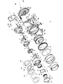
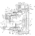
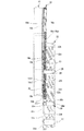
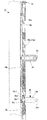
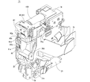
まず、図1ないし図19について、本実施形態のズームレンズ鏡筒71の全体構造を説明する。図6及び図7に示すように、ズームレンズ鏡筒71はデジタルカメラ70に搭載されており、撮影光学系は、物体側から順に、第1レンズ群LG1、シャッタS及び絞りA、第2レンズ群LG2、第3レンズ群LG3、ローパスフィルタ(フィルタ類)LG4及びCCD(固体撮像素子)60からなっている。撮影光学系の光軸はZ1である。この撮影光軸Z1は、ズームレンズ鏡筒71の外観を構成する各環状部材の回動中心軸(回転環の回転軸、以下、鏡筒中心軸Z0と呼ぶ)と平行であり、かつ該鏡筒中心軸Z0に対して下方に偏心している。ズーミングは、第1レンズ群LG1と第2レンズ群LG2を撮影光軸Z1方向に所定の軌跡で進退させることによって行い、フォーカシングは同方向への第3レンズ群LG3の移動で行う。なお、以下の説明中で「光軸方向」という記載は、特に断りがなければ撮影光軸Z1と平行な方向を意味している。
[Overall description of zoom lens barrel]
First, the overall structure of the zoom lens barrel 71 of the present embodiment will be described with reference to FIGS. As shown in FIGS. 6 and 7, the zoom lens barrel 71 is mounted on the digital camera 70, and the photographing optical system includes, in order from the object side, a first lens group LG1, a shutter S and an aperture A, and a second lens. The optical system includes a group LG2, a third lens group LG3, a low-pass filter (filters) LG4, and a CCD (solid-state imaging device) 60. The optical axis of the photographing optical system is Z1. The photographing optical axis Z1 is parallel to the rotation center axis of each of the annular members (the rotation axis of the rotation ring, hereinafter, referred to as the barrel center axis Z0) constituting the external appearance of the zoom lens barrel 71 and the mirror. It is eccentric downward with respect to the cylinder center axis Z0. Zooming is performed by moving the first lens group LG1 and the second lens group LG2 back and forth along a predetermined trajectory in the direction of the photographing optical axis Z1, and focusing is performed by moving the third lens group LG3 in the same direction. In the following description, the term “optical axis direction” means a direction parallel to the photographing optical axis Z1 unless otherwise specified.

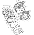
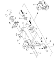
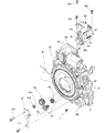
図6及び図7に示すように、カメラボディ72内に固定環22が固定され、この固定環22の後部にCCDホルダ21が固定されている。CCDホルダ21上にはCCDベース板62を介してCCD60が支持され、CCD60の前部に、フィルタホルダ73とパッキン61を介してローパスフィルタLG4が支持されている。フィルタホルダ73は、CCDホルダ21の一部として一体に形成されている。CCDホルダ21の後部には、画像や撮影情報を表示するLCD20が設けられている。   As shown in FIGS. 6 and 7, the fixed ring 22 is fixed in the camera body 72, and the CCD holder 21 is fixed to the rear of the fixed ring 22. The CCD 60 is supported on the CCD holder 21 via a CCD base plate 62, and a low-pass filter LG 4 is supported in front of the CCD 60 via a filter holder 73 and a packing 61. The filter holder 73 is integrally formed as a part of the CCD holder 21. An LCD 20 for displaying images and photographing information is provided at the rear of the CCD holder 21.

固定環22内には、第3レンズ群LG3を保持するAFレンズ枠(3群レンズ枠)51が光軸方向に直進移動可能に支持されている。すなわち、固定環22とCCDホルダ21には、撮影光軸Z1と平行な一対のAFガイド軸52、53の前端部と後端部がそれぞれ固定されており、このAFガイド軸52、53に対してそれぞれ、AFレンズ枠51に形成したガイド孔51a、51bが摺動可能に嵌まっている。本実施形態では、AFガイド軸52とガイド孔51aのクリアランスよりもAFガイド軸53とガイド孔51bのクリアランス大きくなっている。すなわち、AFガイド軸52が主たる(厳密な精度を出す)ガイド軸で、AFガイド軸53はサブ(回り止め)のガイド軸である。また、AFモータ160のドライブシャフトに形成した送りねじに対し、AFナット54が螺合している。図1に示すように、AFナット54は回転規制突起54aを有し、AFレンズ枠51は光軸方向へのガイド溝51mを有し、回転規制突起54aがガイド溝51mに対して摺動可能に嵌まっている。AFレンズ枠51はさらに、AFナット54の後方に位置するストッパ突起51nを有する。AFレンズ枠51は、AF枠付勢ばね55によって前方へ付勢されており、ストッパ突起51nがAFナット54に当て付くことによってAFレンズ枠51の前方移動端が決定される。そしてAFナット54が光軸方向後方へ移動したときに、AFレンズ枠51はAFナット54に押圧されて後方へ移動される。以上の構造により、AFモータ160のドライブシャフトを正逆に回転させると、AFレンズ枠51が光軸方向に進退される。なお、AFレンズ枠51を直接に(AFナット54によらずに)押圧して、AF枠付勢ばね55に抗して後方へ移動させることも可能である。   An AF lens frame (third group lens frame) 51 that holds the third lens group LG3 is supported in the fixed ring 22 so as to be able to move straight in the optical axis direction. That is, the front end and the rear end of a pair of AF guide shafts 52 and 53 parallel to the photographing optical axis Z1 are fixed to the fixed ring 22 and the CCD holder 21, respectively. Guide holes 51a and 51b formed in the AF lens frame 51 are slidably fitted respectively. In the present embodiment, the clearance between the AF guide shaft 53 and the guide hole 51b is larger than the clearance between the AF guide shaft 52 and the guide hole 51a. That is, the AF guide shaft 52 is a main (exactly accurate) guide shaft, and the AF guide shaft 53 is a sub (non-rotating) guide shaft. The AF nut 54 is screwed into a feed screw formed on the drive shaft of the AF motor 160. As shown in FIG. 1, the AF nut 54 has a rotation restricting protrusion 54a, the AF lens frame 51 has a guide groove 51m in the optical axis direction, and the rotation restricting protrusion 54a can slide with respect to the guide groove 51m. Is stuck in. The AF lens frame 51 further has a stopper projection 51n located behind the AF nut 54. The AF lens frame 51 is urged forward by an AF frame urging spring 55, and the forward movement end of the AF lens frame 51 is determined by the stopper projection 51 n abutting against the AF nut 54. When the AF nut 54 moves rearward in the optical axis direction, the AF lens frame 51 is pressed by the AF nut 54 and moves rearward. With the above structure, when the drive shaft of the AF motor 160 is rotated in the normal or reverse direction, the AF lens frame 51 is moved forward and backward in the optical axis direction. It is also possible to directly press the AF lens frame 51 (without using the AF nut 54) and move the AF lens frame 51 backward against the AF frame urging spring 55.

図5に示すように、固定環22の上部には、ズームモータ150と減速ギヤボックス74が支持されている。減速ギヤボックス74は内部に減速ギヤ列を有し、ズームモータ150の駆動力をズームギヤ28に伝える。ズームギヤ28は、撮影光軸Z1と平行なズームギヤ軸29によって固定環22に枢着されている。ズームモータ150とAFモータ160は、固定環22の外周面に配設したレンズ駆動制御FPC(フレキシブルプリント回路)基板75を介して、カメラの制御回路140(図19)により制御される。   As shown in FIG. 5, a zoom motor 150 and a reduction gear box 74 are supported on the upper part of the fixed ring 22. The reduction gear box 74 has a reduction gear train therein and transmits the driving force of the zoom motor 150 to the zoom gear 28. The zoom gear 28 is pivotally attached to the fixed ring 22 by a zoom gear shaft 29 parallel to the photographing optical axis Z1. The zoom motor 150 and the AF motor 160 are controlled by a camera control circuit 140 (FIG. 19) via a lens drive control FPC (flexible printed circuit) board 75 disposed on the outer peripheral surface of the fixed ring 22.

固定環22の内周面には、雌ヘリコイド22a、撮影光軸Z1と平行な3本の直進案内溝22b、雌ヘリコイド22aと平行な3本の斜行溝22c、及び各斜行溝22cの前端部に連通する周方向への回転摺動溝22dが形成されている。回転摺動溝22dは固定環22の前端部付近に形成され、この回転摺動溝22dの直後の前方環状領域22zには雌ヘリコイド22aが形成されていない(図8参照)。   On the inner peripheral surface of the fixed ring 22, a female helicoid 22a, three rectilinear guide grooves 22b parallel to the photographing optical axis Z1, three oblique grooves 22c parallel to the female helicoid 22a, and each oblique groove 22c are formed. A circumferential sliding groove 22d communicating with the front end is formed in the circumferential direction. The rotary sliding groove 22d is formed near the front end of the fixed ring 22, and the female helicoid 22a is not formed in the front annular region 22z immediately after the rotary sliding groove 22d (see FIG. 8).

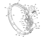
ヘリコイド環(回転環)18は、雌ヘリコイド22aに螺合する雄ヘリコイド18aと、斜行溝22c及び回転摺動溝22dに係合する回転摺動突起18bとを外周面に有している(図4、図9)。雄ヘリコイド18a上には、撮影光軸Z1と平行なギヤ歯を有するスパーギヤ部(環状ギヤ)18cが形成されており、スパーギヤ部18cはズームギヤ28に対して螺合する。従って、ズームギヤ28からスパーギヤ部18cへ回転力が与えられたとき、ヘリコイド環18は、雌ヘリコイド22aと雄ヘリコイド18aが螺合関係にある状態では回転しながら光軸方向へ進退し、ある程度前方に移動すると、雄ヘリコイド18aが雌ヘリコイド22aから外れ、回転摺動溝22dと回転摺動突起18bの係合関係によって鏡筒中心軸Z0を中心とする周方向回転のみを行う。   The helicoid ring (rotating ring) 18 has a male helicoid 18a screwed to the female helicoid 22a and a rotary sliding protrusion 18b engaged with the oblique groove 22c and the rotary sliding groove 22d on the outer peripheral surface ( 4 and 9). A spur gear portion (annular gear) 18c having gear teeth parallel to the photographing optical axis Z1 is formed on the male helicoid 18a, and the spur gear portion 18c is screwed with the zoom gear 28. Accordingly, when a rotational force is applied from the zoom gear 28 to the spur gear portion 18c, the helicoid ring 18 advances and retreats in the optical axis direction while rotating when the female helicoid 22a and the male helicoid 18a are in a screwing relationship with each other. When the male helicoid 18a moves, the male helicoid 18a is disengaged from the female helicoid 22a, and only the circumferential rotation about the lens barrel center axis Z0 is performed by the engagement relationship between the rotary sliding groove 22d and the rotary sliding protrusion 18b.

斜行溝22cは、雌ヘリコイド22aと雄ヘリコイド18aが螺合する段階で回転摺動突起18bと固定環22の干渉を避けるために形成された逃げ溝であり、斜行溝22cは雌ヘリコイド22aの底部よりも深くなっている。雌ヘリコイド22aは、各斜行溝22cを挟む一対のヘリコイド山の周方向間隔が他のヘリコイド山の周方向間隔よりも広くなっており、雄ヘリコイド18aは、この周方向間隔の広いヘリコイド山に係合するべく、回転摺動突起18bの後方に位置する3つのヘリコイド山18a-Wが他のヘリコイド山よりも周方向に幅広になっている。   The skew groove 22c is a relief groove formed to avoid interference between the rotary sliding protrusion 18b and the fixed ring 22 when the female helicoid 22a and the male helicoid 18a are screwed, and the skew groove 22c is a female helicoid 22a. Is deeper than the bottom. In the female helicoid 22a, the circumferential interval between a pair of helicoid mountains sandwiching each of the oblique grooves 22c is wider than the circumferential interval between the other helicoid mountains, and the male helicoid 18a is mounted on the helicoid mountain having the wide circumferential interval. For engagement, the three helicoid peaks 18a-W located behind the rotary sliding protrusion 18b are circumferentially wider than the other helicoid peaks.

固定環22にはさらに、その外周面と回転摺動溝22dとを貫通するストッパ挿脱孔が形成され、このストッパ挿脱孔22eに対し、撮影領域を越えるヘリコイド環18の回動を規制するための分解ストッパ26が着脱可能となっている。   The fixed ring 22 is further formed with a stopper insertion / removal hole penetrating the outer peripheral surface and the rotary sliding groove 22d, and restricts the rotation of the helicoid ring 18 beyond the photographing region with respect to the stopper insertion / removal hole 22e. Disassembly stopper 26 is detachable.

ヘリコイド環18の前端部内周面に形成した回転伝達凹部18d(図4、図10)に対し、第3外筒15の後端部から後方に突設した回転伝達突起15a(図11)が嵌入されている。回転伝達凹部18dと回転伝達突起15aはそれぞれ、周方向に位置を異ならせて3箇所設けられており、周方向位置が対応するそれぞれの回転伝達突起15aと回転伝達凹部18dは、鏡筒中心軸Z0に沿う方向への相対摺動は可能に結合し、該鏡筒中心軸Z0を中心とする周方向には相対回動不能に結合されている。すなわち、第3外筒15とヘリコイド環18は一体に回転する。また、ヘリコイド環18には、回転摺動突起18bの内径側の一部領域を切り欠いて嵌合凹部18eが形成されており、該嵌合凹部18eに嵌合する嵌合突起15bは、回転摺動突起18bが回転摺動溝22dに係合するとき、同時に回転摺動溝22dに係合する(図6の鏡筒上半断面参照)。   A rotation transmitting projection 15a (FIG. 11) projecting rearward from the rear end of the third outer cylinder 15 fits into a rotation transmitting recess 18d (FIGS. 4 and 10) formed on the inner peripheral surface of the front end of the helicoid ring 18. Have been. The rotation transmitting recesses 18d and the rotation transmitting projections 15a are provided at three positions at different positions in the circumferential direction, and the rotation transmitting projections 15a and the rotation transmitting recesses 18d corresponding to the circumferential positions correspond to the center axis of the lens barrel. Relative sliding in the direction along Z0 is connected so as to be possible, and relative rotation is not possible in the circumferential direction around the lens barrel center axis Z0. That is, the third outer cylinder 15 and the helicoid ring 18 rotate integrally. Further, the helicoid ring 18 is formed with a fitting recess 18e by cutting out a part of the rotation sliding protrusion 18b on the inner diameter side, and the fitting protrusion 15b fitted into the fitting recess 18e is rotated. When the sliding protrusion 18b engages with the rotating sliding groove 22d, it simultaneously engages with the rotating sliding groove 22d (see the upper half section of the lens barrel in FIG. 6).

第3外筒15とヘリコイド環18の間には、互いを光軸方向での離間方向へ付勢する3つの離間方向付勢ばね25が設けられている。離間方向付勢ばね25は圧縮コイルばねからなり、その後端部がヘリコイド環18の前端部に開口するばね挿入凹部18fに収納され、前端部が第3外筒15のばね当付凹部15cに当接している。この離間方向付勢ばね25によって、回転摺動溝22dの前側壁面に向けて嵌合突起15bを押圧し、かつ回転摺動溝22dの後側壁面に向けて回転摺動突起18bを押圧することで、固定環22に対する第3外筒15とヘリコイド環18の光軸方向のバックラッシュが除去される。   Between the third outer cylinder 15 and the helicoid ring 18, there are provided three separation-direction biasing springs 25 for biasing each other in the separation direction in the optical axis direction. The separation-direction urging spring 25 is formed of a compression coil spring, and its rear end is housed in a spring insertion recess 18 f that opens to the front end of the helicoid ring 18, and its front end contacts the spring-attached recess 15 c of the third outer cylinder 15. In contact. Pressing the fitting projection 15b toward the front wall surface of the rotary sliding groove 22d and pressing the rotary sliding protrusion 18b toward the rear wall surface of the rotary sliding groove 22d by the separating direction urging spring 25. Thus, the backlash of the third outer cylinder 15 and the helicoid ring 18 with respect to the fixed ring 22 in the optical axis direction is eliminated.

第3外筒15の内周面には、内径方向に突設された爪状の相対回動案内突起15dと、鏡筒中心軸Z0を中心とする周方向溝15eと、撮影光軸Z1と平行な3本のローラ嵌合溝15fとが形成されている(図4、図11)。相対回動案内突起15dは、周方向に位置を異ならせて複数設けられている。ローラ嵌合溝15fは、回転伝達突起15aに対応する周方向位置に形成されており、その後端部は、回転伝達突起15aを貫通して後方へ向け開口されている。また、ヘリコイド環18の内周面には鏡筒中心軸Z0を中心とする周方向溝18gが形成されている(図4、図10)。この第3外筒15とヘリコイド環18の結合体の内側には直進案内環14が支持される。直進案内環14の外周面には光軸方向の後方から順に、外径方向へ突出する3つの直進案内突起14aと、それぞれ周方向に位置を異ならせて複数設けた爪状の相対回動案内突起14b及び相対回動案内突起14cと、鏡筒中心軸Z0を中心とする周方向溝14dとが形成されている(図4、図12)。直進案内環14は、直進案内突起14aを直進案内溝22bに係合させることで、固定環22に対し光軸方向に直進案内される。また第3外筒15は、周方向溝15eを相対回動案内突起14cに係合させ、相対回動案内突起15dを周方向溝14dに係合させることで、直進案内環14に対して相対回動可能に結合される。周方向溝15eと相対回動案内突起14c、周方向溝14dと相対回動案内突起15dはそれぞれ、光軸方向には若干相対移動可能なように遊嵌している。さらにヘリコイド環18も、周方向溝18gを相対回動案内突起14bに係合させることで、直進案内環14に対して相対回動可能に結合される。周方向溝18gと相対回動案内突起14bは光軸方向には若干相対移動可能なように遊嵌している。   On the inner peripheral surface of the third outer cylinder 15, a claw-shaped relative rotation guide projection 15d protruding in the inner diameter direction, a circumferential groove 15e centered on the lens barrel center axis Z0, and a photographing optical axis Z1 are provided. Three parallel roller fitting grooves 15f are formed (FIGS. 4 and 11). A plurality of relative rotation guide protrusions 15d are provided at different positions in the circumferential direction. The roller fitting groove 15f is formed at a circumferential position corresponding to the rotation transmitting protrusion 15a, and a rear end portion thereof is opened rearward through the rotation transmitting protrusion 15a. A circumferential groove 18g centering on the lens barrel center axis Z0 is formed on the inner circumferential surface of the helicoid ring 18 (FIGS. 4 and 10). A straight guide ring 14 is supported inside the combined body of the third outer cylinder 15 and the helicoid ring 18. Three rectilinear guide protrusions 14a protruding in the radial direction are sequentially provided on the outer peripheral surface of the rectilinear guide ring 14 from the rear in the optical axis direction, and a plurality of claw-shaped relative rotation guides provided at different positions in the circumferential direction. A protrusion 14b, a relative rotation guide protrusion 14c, and a circumferential groove 14d about the lens barrel center axis Z0 are formed (FIGS. 4 and 12). The linear guide ring 14 is guided linearly in the optical axis direction with respect to the fixed ring 22 by engaging the linear guide protrusion 14a with the linear guide groove 22b. Further, the third outer cylinder 15 engages the circumferential groove 15e with the relative rotation guide protrusion 14c and engages the relative rotation guide protrusion 15d with the circumferential groove 14d, so that the third outer cylinder 15 is It is rotatably connected. The circumferential groove 15e and the relative rotation guide protrusion 14c, and the circumferential groove 14d and the relative rotation guide protrusion 15d are each loosely fitted so as to be relatively movable in the optical axis direction. Further, the helicoid ring 18 is also relatively rotatably coupled to the rectilinear guide ring 14 by engaging the circumferential groove 18g with the relative rotation guide protrusion 14b. The circumferential groove 18g and the relative rotation guide protrusion 14b are loosely fitted so as to be able to relatively move relatively in the optical axis direction.

直進案内環14には、内周面と外周面を貫通する3つのローラ案内貫通溝14eが形成されている。各ローラ案内貫通溝14eは、図12に示すように、周方向へ向け形成された平行な前後の周方向溝部14e-1、14e-2と、この両周方向溝部14e-1及び14e-2を接続するリード溝部14e-3とを有する。それぞれのローラ案内貫通溝14eに対し、カム環11の外周面に設けたカム環ローラ32が嵌まっている。カム環ローラ32は、ローラ固定ねじ32aを介してカム環11に固定されており、周方向へ位置を異ならせて3つ設けられている。カム環ローラ32はさらに、ローラ案内貫通溝14eを貫通して第3外筒15内周面のローラ嵌合溝15fに嵌まっている。各ローラ嵌合溝15fの前端部付近には、ローラ付勢ばね17に設けた3つのローラ押圧片17aが嵌っている(図11)。ローラ押圧片17aは、カム環ローラ32が周方向溝部14e-1に係合するときに該カム環ローラ32に当接して後方へ押圧し、カム環ローラ32とローラ案内貫通溝14e(周方向溝部14e-1)との間のバックラッシュを取る。   The linear guide ring 14 is formed with three roller guide through grooves 14e penetrating the inner peripheral surface and the outer peripheral surface. As shown in FIG. 12, each of the roller guide through grooves 14e includes parallel front and rear circumferential grooves 14e-1 and 14e-2 formed in the circumferential direction, and both circumferential grooves 14e-1 and 14e-2. And a lead groove 14e-3 for connecting the A cam ring roller 32 provided on the outer peripheral surface of the cam ring 11 is fitted into each roller guide through groove 14e. The cam ring rollers 32 are fixed to the cam ring 11 via roller fixing screws 32a, and three cam ring rollers are provided at different positions in the circumferential direction. The cam ring roller 32 further penetrates the roller guide through groove 14e and is fitted in the roller fitting groove 15f on the inner peripheral surface of the third outer cylinder 15. Near the front end of each roller fitting groove 15f, three roller pressing pieces 17a provided on the roller urging spring 17 are fitted (FIG. 11). The roller pressing piece 17a comes into contact with the cam ring roller 32 and presses backward when the cam ring roller 32 engages with the circumferential groove portion 14e-1, and the cam ring roller 32 and the roller guide through groove 14e (in the circumferential direction). Backlash between the groove 14e-1) is removed.

以上の構造から、固定環22からカム環11までの繰り出しの態様が理解される。すなわち、ズームモータ150によってズームギヤ28を鏡筒繰出方向に回転駆動すると、雌ヘリコイド22aと雄ヘリコイド18aの関係によってヘリコイド環18が回転しながら前方に繰り出される。ヘリコイド環18と第3外筒15はそれぞれ、周方向溝14d、15e及び18gと相対回動案内突起15d、14c及び14bの係合関係によって、直進案内環14に対して相対回動可能かつ回転軸方向(鏡筒中心軸Z0に沿う方向)へは共に移動するように結合されているため、ヘリコイド環18が回転繰出されると、第3外筒15も同方向に回転しながら前方に繰り出され、直進案内環14はヘリコイド環18及び第3外筒15と共に前方へ直進移動する。また、第3外筒15の回転力はローラ嵌合溝15fとカム環ローラ32を介してカム環11に伝達される。カム環ローラ32はローラ案内貫通溝14eにも嵌まっているため、直進案内環14に対してカム環11は、リード溝部14e-3の形状に従って回転しながら前方に繰り出される。前述の通り、直進案内環14自体も第3外筒15及びヘリコイド環18と共に前方に直進移動しているため、結果としてカム環11には、リード溝部14e-3に従う回転繰出分と、直進案内環14の前方への直進移動分とを合わせた光軸方向移動量が与えられる。   From the structure described above, the manner in which the fixed ring 22 extends from the cam ring 11 is understood. That is, when the zoom gear 28 is rotationally driven by the zoom motor 150 in the lens barrel extending direction, the helicoid ring 18 is extended forward while rotating due to the relationship between the female helicoid 22a and the male helicoid 18a. The helicoid ring 18 and the third outer cylinder 15 are relatively rotatable and rotatable with respect to the rectilinear guide ring 14 due to the engagement relationship between the circumferential grooves 14d, 15e and 18g and the relative rotation guide projections 15d, 14c and 14b, respectively. The third outer cylinder 15 is also extended forward while rotating in the same direction when the helicoid ring 18 is rotationally extended since the coupling is performed so as to move together in the axial direction (the direction along the lens barrel center axis Z0). Then, the straight guide ring 14 moves straight forward together with the helicoid ring 18 and the third outer cylinder 15. The rotational force of the third outer cylinder 15 is transmitted to the cam ring 11 via the roller fitting groove 15f and the cam ring roller 32. Since the cam ring roller 32 is also fitted into the roller guide through groove 14e, the cam ring 11 is extended forward with respect to the straight guide ring 14 while rotating according to the shape of the lead groove 14e-3. As described above, since the rectilinear guide ring 14 itself is also rectilinearly moving forward together with the third outer cylinder 15 and the helicoid ring 18, as a result, the cam ring 11 is provided with the rotation extension according to the lead groove 14e-3 and the rectilinear guide. The moving amount in the optical axis direction is given by adding the amount of forward movement of the ring 14 to the front.

以上の繰出動作は雄ヘリコイド18aと雌ヘリコイド22aが螺合している間行われ、このとき回転摺動突起18bは斜行溝22c内を移動している。ヘリコイド環18と第3外筒15が所定量繰り出されると、雄ヘリコイド18aと雌ヘリコイド22aの螺合が解除されて、やがて回転摺動突起18bと嵌合突起15bが斜行溝22cから回転摺動溝22d内へ入る。すると、ヘリコイドによる回転繰出力が作用しなくなるため、ヘリコイド環18及び第3外筒15は、回転摺動突起18b及び嵌合突起15bと回転摺動溝22dとの係合関係によって光軸方向の一定位置で回動のみを行うようになる。また、回転摺動突起18bが斜行溝22cから回転摺動溝22d内へ入るのとほぼ同時に、カム環ローラ32は貫通ガイド溝14eの周方向溝部14e-1に入る。するとカム環11に対しても前方への移動力が与えられなくなり、カム環11は第3外筒15の回転に応じて一定位置で回動のみ行うようになる。   The above-described feeding operation is performed while the male helicoid 18a and the female helicoid 22a are screwed together, and at this time, the rotary sliding projection 18b moves in the oblique groove 22c. When the helicoid ring 18 and the third outer cylinder 15 are extended by a predetermined amount, the screw engagement between the male helicoid 18a and the female helicoid 22a is released, and the rotary sliding projection 18b and the fitting projection 15b are eventually rotated from the oblique groove 22c. It enters the moving groove 22d. Then, since the rotation repetition output by the helicoid does not work, the helicoid ring 18 and the third outer cylinder 15 are moved in the optical axis direction by the engagement relationship between the rotation sliding protrusion 18b and the fitting protrusion 15b and the rotation sliding groove 22d. Only rotation is performed at a fixed position. At substantially the same time when the rotary sliding protrusion 18b enters the rotary sliding groove 22d from the oblique groove 22c, the cam ring roller 32 enters the circumferential groove 14e-1 of the through guide groove 14e. Then, no forward moving force is applied to the cam ring 11, and the cam ring 11 only rotates at a fixed position according to the rotation of the third outer cylinder 15.

ズームギヤ28を鏡筒収納方向に回転駆動させると、以上と逆の動作が行われる。カム環ローラ32がローラ案内貫通溝14eの周方向溝部14e-2に入るまでヘリコイド環18に回転を与えると、以上の各鏡筒部材が図7に示す位置まで後退する。   When the zoom gear 28 is driven to rotate in the lens barrel housing direction, the reverse operation is performed. When the helicoid ring 18 is rotated until the cam ring roller 32 enters the circumferential groove 14e-2 of the roller guide through groove 14e, each of the above-mentioned lens barrel members is retracted to the position shown in FIG.

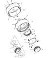
続いて、カム環11より先の構造を説明する。直進案内環14の内周面には、撮影光軸Z1と平行な3つの第1直進案内溝14f及び6つの第2直進案内溝14gが、それぞれ周方向に位置を異ならせて形成されている。第1直進案内溝14fは、6つのうち3つの第2直進案内溝14gの両側に位置する一対の溝部からなっており、この3つの第1直進案内溝14fに対し、2群直進案内環10に設けた3つの股状突起10a(図3、図15)が摺動可能に係合している。一方、第2直進案内溝14gに対しては、第2外筒13の後端部外周面に突設した6つの直進案内突起13a(図2、図17)が摺動可能に係合している。したがって、第2外筒13と2群直進案内環10はいずれも、直進案内環14を介して光軸方向に直進案内されている。   Subsequently, the structure before the cam ring 11 will be described. On the inner peripheral surface of the rectilinear guide ring 14, three first rectilinear guide grooves 14f and six second rectilinear guide grooves 14g parallel to the photographing optical axis Z1 are formed at different positions in the circumferential direction. . The first rectilinear guide grooves 14f include a pair of grooves located on both sides of three of the six second rectilinear guide grooves 14g. The three crotch-shaped protrusions 10a (FIGS. 3 and 15) provided on the front panel are slidably engaged. On the other hand, the six rectilinear guide projections 13a (FIGS. 2 and 17) protruding from the outer peripheral surface of the rear end of the second outer cylinder 13 are slidably engaged with the second rectilinear guide grooves 14g. I have. Therefore, both the second outer cylinder 13 and the second group straight guide ring 10 are guided straight through the straight guide ring 14 in the optical axis direction.

2群直進案内環10は、第2レンズ群LG2を支持する2群レンズ移動枠8を直進案内するための部材であり、第2外筒13は、第1レンズ群LG1を支持する第1外筒12を直進案内するための部材である。   The second group straight guide ring 10 is a member for guiding the second group lens moving frame 8 that supports the second lens group LG2 straight, and the second outer cylinder 13 is a first outer cylinder that supports the first lens group LG1. It is a member for guiding the cylinder 12 straight.

まず第2レンズ群LG2の支持構造を説明する。2群直進案内環10は、3つの股状突起10aを接続するリング部10bから前方へ向けて、3つの直進案内キー10cを突出させている(図3、図15)。図6及び図7に示すように、リング部10bの外縁部は、カム環11の後端部内周面に形成した周方向溝11eに対し相対回転は可能で光軸方向の相対移動は不能に係合しており、直進案内キー10cはカム環11の内側に延出されている。各直進案内キー10cは、撮影光軸Z1と平行な一対のガイド面を側面に有しており、このガイド面を、カム環11の内側に支持された2群レンズ移動枠8の直進案内溝8aに係合させることによって、2群レンズ移動枠8を軸方向に直進案内している。直進案内溝8aは、2群レンズ移動枠8の外周面側に形成されている。   First, the support structure of the second lens group LG2 will be described. The second group straight guide ring 10 has three straight guide keys 10c protruding forward from a ring portion 10b connecting the three crotch-shaped protrusions 10a (FIGS. 3 and 15). As shown in FIGS. 6 and 7, the outer edge of the ring portion 10b can rotate relative to the circumferential groove 11e formed on the inner peripheral surface of the rear end of the cam ring 11, but cannot move relative to the optical axis. The straight guide key 10c is extended inside the cam ring 11. Each of the rectilinear guide keys 10 c has a pair of guide surfaces parallel to the photographing optical axis Z <b> 1, and the guide surfaces are formed by the rectilinear guide grooves of the second lens group moving frame 8 supported inside the cam ring 11. The second group lens moving frame 8 is guided linearly in the axial direction by engaging with the lens 8a. The rectilinear guide groove 8 a is formed on the outer peripheral surface side of the second group lens moving frame 8.

なお、2群直進案内環10には周方向に位置を異ならせて直進案内キー10cが3つ設けられているが、そのうちひとつの直進案内キー10c-Wは、後述する露出制御用のFPC(フレキシブルプリント回路)基板77の支持部材を兼ねるために、残る2つの直進案内キー10cよりも周方向に幅広になっている。幅広の直進案内キー10c-Wには、リング部10bとの接続部分近傍を一部切り欠いて径方向へ貫通するFPC通し孔10dが形成されており、図6に示すように、露出制御FPC基板77は、該FPC通し孔10dを通してリング部10bの後方から直進案内キー10c-Wの外周面側へ延出され、直進案内キー10c-Wの先端部で後方に折り曲げられている。これに対応して、3つの直進案内溝8aのうちひとつは、幅広の直進案内キー10c-Wが係合可能な幅広の直進案内溝8a-Wとなっている。該直進案内溝8a-Wの中央部は、露出制御FPC基板77を通すことが可能な貫通部になっており、この貫通部の両側に直進案内キー10c-Wを支持するための有底部が形成されている。これに対し、残る2つの直進案内溝8aはいずれも、2群レンズ移動枠8の外周面側に形成された有底溝となっている。2群レンズ移動枠8と2群直進案内環10は、直進案内キー10c-Wが直進案内溝8a-Wに係合可能な特定の回転位相でのみ組み合わせることができる。   The second group straight guide ring 10 is provided with three straight guide keys 10c at different positions in the circumferential direction, and one of the straight guide keys 10c-W is provided with an exposure control FPC (described later). In order to also serve as a support member for the flexible printed circuit (PCB) board 77, the width is circumferentially wider than the remaining two straight guide keys 10c. The wide straight guide key 10c-W is formed with an FPC through hole 10d which is partially cut away in the vicinity of the connection portion with the ring portion 10b and penetrates in the radial direction, and as shown in FIG. The board 77 extends from the rear of the ring portion 10b to the outer peripheral surface side of the linear guide key 10c-W through the FPC through hole 10d, and is bent rearward at the tip of the linear guide key 10c-W. Correspondingly, one of the three rectilinear guide grooves 8a is a wide rectilinear guide groove 8a-W to which the wide rectilinear guide key 10c-W can be engaged. A central portion of the straight guide groove 8a-W is a through portion through which the exposure control FPC board 77 can pass. A bottom portion for supporting the straight guide key 10c-W is provided on both sides of the through portion. Is formed. On the other hand, the remaining two rectilinear guide grooves 8 a are both bottomed grooves formed on the outer peripheral surface side of the second group lens moving frame 8. The second group lens moving frame 8 and the second group straight guide ring 10 can be combined only in a specific rotation phase in which the straight guide keys 10c-W can engage with the straight guide grooves 8a-W.

カム環11の内周面には2群案内カム溝11aが形成されている。図14に示すように、2群案内カム溝11aは、光軸方向及び周方向に位置を異ならせた前方カム溝11a-1と後方カム溝11a-2からなっている。前方カム溝11a-1と後方カム溝11a-2はいずれも、同形状の基礎軌跡αをトレースして形成されたカム溝であるが、それぞれが基礎軌跡α全域をカバーしているのではなく、前方カム溝11a-1と後方カム溝11a-2では基礎軌跡α上に占める領域の一部が異なっている。基礎軌跡とは、ズーム領域及び収納用領域を含む全ての鏡筒使用領域(使用領域)と、鏡筒の組立分解用領域とを含む概念上のカム溝形状である。つまり、鏡筒使用領域とはこのカム溝形状によって2群レンズ移動枠8の移動が制御されうる領域のことであり、組立分解領域と区別する意味で用いられている。また、ズーム領域とは、鏡筒使用領域の中でも特にワイド端とテレ端の間の移動を制御するための領域であり、収納用領域と区別する意味で用いられている。カム環11には、一対の前方カム溝11a-1と後方カム溝11a-2を1グループとした場合、周方向に等間隔で3グループの2群案内カム溝11aが形成されている。   A second group guide cam groove 11 a is formed on the inner peripheral surface of the cam ring 11. As shown in FIG. 14, the second group guide cam groove 11a includes a front cam groove 11a-1 and a rear cam groove 11a-2 whose positions are different in the optical axis direction and the circumferential direction. Each of the front cam groove 11a-1 and the rear cam groove 11a-2 is a cam groove formed by tracing the same base locus α, but does not cover the entire area of the base locus α. The front cam groove 11a-1 and the rear cam groove 11a-2 differ from each other in a part of the area occupied on the basic locus α. The basic trajectory is a conceptual cam groove shape including all the lens barrel use areas (use areas) including the zoom area and the storage area, and the lens barrel assembly / disassembly area. That is, the lens barrel use area is an area in which the movement of the second lens group moving frame 8 can be controlled by the cam groove shape, and is used to distinguish it from the assembly and disassembly area. Further, the zoom area is an area for controlling movement between the wide end and the tele end particularly in the lens barrel use area, and is used to distinguish it from the storage area. When a pair of the front cam groove 11a-1 and the rear cam groove 11a-2 are formed as one group, the cam ring 11 is formed with three groups of second group guide cam grooves 11a at equal intervals in the circumferential direction.

2群案内カム溝11aに対して、2群レンズ移動枠8の外周面に設けた2群用カムフォロア8bが係合している。2群案内カム溝11aと同様に2群用カムフォロア8bも、光軸方向及び周方向に位置を異ならせた一対の前方カムフォロア8b-1と後方カムフォロア8b-2を1グループとして周方向に等間隔で3グループが設けられており、各前方カムフォロア8b-1は前方カム溝11a-1に係合し、各後方カムフォロア8b-2は後方カム溝11a-2に係合するように光軸方向及び周方向の間隔が定められている。   The second group cam follower 8b provided on the outer peripheral surface of the second group lens moving frame 8 is engaged with the second group guide cam groove 11a. Similarly to the second group guide cam groove 11a, the second group cam followers 8b are also circumferentially equally spaced as a group of a pair of front cam followers 8b-1 and rear cam followers 8b-2 whose positions are different in the optical axis direction and the circumferential direction. The front cam followers 8b-1 engage with the front cam grooves 11a-1, and the rear cam followers 8b-2 engage with the rear cam grooves 11a-2 in the optical axis direction. A circumferential interval is defined.

2群レンズ移動枠8は2群直進案内環10を介して光軸方向に直進案内されているため、カム環11が回転すると、2群案内カム溝11aに従って、2群レンズ移動枠8が光軸方向へ所定の軌跡で移動する。   Since the second group lens moving frame 8 is guided linearly in the optical axis direction via the second group linear guide ring 10, when the cam ring 11 rotates, the second group lens moving frame 8 is driven in accordance with the second group guide cam groove 11a. It moves along a predetermined trajectory in the axial direction.

2群レンズ移動枠8の内側には、第2レンズ群LG2を保持する2群レンズ枠6が支持されている。2群レンズ枠6は、一対の2群レンズ枠支持板36、37に対し、2群回動軸33を介して軸支されており、2群枠支持板36、37が支持板固定ビス66によって2群レンズ移動枠8に固定されている。2群回動軸33は撮影光軸Z1と平行でかつ撮影光軸Z1に対して偏心しており、2群レンズ枠6は、2群回動軸33を回動中心として、第2レンズ群LG2の光軸を撮影光軸Z1と一致させる撮影用位置(図6)と、第2レンズ群LG2の光軸を撮影光軸Z1から偏心した退避光軸Z2へと変位させる収納用退避位置(図7)とに回動することができる。2群レンズ移動枠8には、2群レンズ枠6を上記撮影用位置で回動規制する回動規制ピン35が設けられていて、2群レンズ枠6は、2群レンズ枠戻しばね39によって該回動規制ピン35との当接方向へ回動付勢されている。軸方向押圧ばね38は、2群レンズ枠6の光軸方向のバックラッシュ取りを行う。   Inside the second group lens moving frame 8, a second group lens frame 6 that holds the second lens group LG2 is supported. The second group lens frame 6 is supported by a pair of second group lens frame support plates 36 and 37 via a second group rotation shaft 33, and the second group frame support plates 36 and 37 are supported plate fixing screws 66. To the second group lens moving frame 8. The second-group rotation axis 33 is parallel to the imaging optical axis Z1 and is eccentric with respect to the imaging optical axis Z1, and the second-group lens frame 6 has the second lens group LG2 with the second-group rotation axis 33 as the rotation center. A photographing position (FIG. 6) where the optical axis of the second lens group LG2 coincides with the photographing optical axis Z1, and a retracting position (FIG. 6) for displacing the optical axis of the second lens group LG2 from the photographing optical axis Z1 to the retracted optical axis Z2. 7). The second group lens moving frame 8 is provided with a rotation restricting pin 35 for restricting the second group lens frame 6 from rotating at the photographing position. The second group lens frame 6 is moved by a second group lens frame returning spring 39. It is urged to rotate in the direction of contact with the rotation restricting pin 35. The axial pressing spring 38 performs backlash removal of the second lens group frame 6 in the optical axis direction.

2群レンズ枠6は、光軸方向には2群レンズ移動枠8と一体に移動する。CCDホルダ21には2群レンズ枠6に係合可能な位置にカム突起21a(図4)が前方に向けて突設されており、図7のように2群レンズ移動枠8が収納方向に移動してCCDホルダ21に接近すると、該カム突起21aの先端部に形成したカム面が、2群レンズ枠6に係合して上記の収納用退避位置に回動させる。   The second group lens frame 6 moves integrally with the second group lens moving frame 8 in the optical axis direction. A cam projection 21a (FIG. 4) projects forward from the CCD holder 21 at a position where it can be engaged with the second group lens frame 6. As shown in FIG. When it moves and approaches the CCD holder 21, the cam surface formed at the tip of the cam projection 21a engages with the second lens group frame 6 and rotates to the above-mentioned retracted position for storage.

続いて第1レンズ群LG1の支持構造を説明する。直進案内環14を介して光軸方向に直進案内された第2外筒13の内周面には、周方向に位置を異ならせて3つの直進案内溝13bが光軸方向へ形成されており、各直進案内溝13bに対し、第1外筒12の後端部付近の外周面に形成した3つの係合突起12aが摺動可能に嵌合している(図2、図17及び図18参照)。すなわち、第1外筒12は、直進案内環14と第2外筒13を介して光軸方向に直進案内されている。また、第2外筒13は後端部付近の内周面に、周方向へ向かう内径フランジ13cを有し、この内径フランジ13cがカム環11の外周面に設けた周方向溝11cに摺動可能に係合することで、第2外筒13は、カム環11に対して相対回転可能かつ光軸方向の相対移動は不能に結合されている。一方、第1外筒12は、内径方向に突出する3つの1群用ローラ31を有し、それぞれの1群用ローラ31が、カム環11の外周面に3本形成した1群案内カム溝11bに摺動可能に嵌合している。   Subsequently, a support structure of the first lens group LG1 will be described. On the inner peripheral surface of the second outer cylinder 13 guided straight in the optical axis direction via the straight guide ring 14, three rectilinear guide grooves 13b are formed in the optical axis direction at positions different in the circumferential direction. The three engagement projections 12a formed on the outer peripheral surface near the rear end of the first outer cylinder 12 are slidably fitted into the respective linear guide grooves 13b (FIGS. 2, 17, and 18). reference). That is, the first outer cylinder 12 is guided linearly in the optical axis direction via the straight guide ring 14 and the second outer cylinder 13. The second outer cylinder 13 has an inner peripheral flange 13c on the inner peripheral surface in the vicinity of the rear end thereof, and the inner peripheral flange 13c slides in a circumferential groove 11c provided on the outer peripheral surface of the cam ring 11. By engaging as much as possible, the second outer cylinder 13 is coupled to the cam ring 11 so as to be rotatable relative to the cam ring 11 and not to move relative to the optical axis. On the other hand, the first outer cylinder 12 has three first-group rollers 31 protruding in the inner diameter direction, and each first-group roller 31 has three first-group guide cam grooves formed on the outer peripheral surface of the cam ring 11. 11b is slidably fitted.

第1外筒12内には、1群調整環2を介して1群レンズ枠1が支持されている。1群レンズ枠1には第1レンズ群LG1が固定され、その外周面に形成した雄調整ねじ1aが、1群調整環2の内周面に形成した雌調整ねじ2aに螺合している。この調整ねじの螺合位置を調整することよって、1群レンズ枠1は1群調整環2に対して光軸方向に位置調整可能となっている。   The first lens barrel 1 is supported in the first outer cylinder 12 via a first lens adjusting ring 2. The first lens group LG1 is fixed to the first group lens frame 1, and a male adjustment screw 1a formed on the outer peripheral surface thereof is screwed with a female adjustment screw 2a formed on the inner peripheral surface of the first group adjustment ring 2. . By adjusting the screw position of the adjusting screw, the position of the first lens group frame 1 with respect to the first lens group adjusting ring 2 can be adjusted in the optical axis direction.

1群調整環2は外径方向に突出する一対の(図2には一つのみを図示)ガイド突起2bを有し、この一対のガイド突起2bが、第1外筒12の内周面側に形成した一対の1群調整環ガイド溝12bに摺動可能に係合している。1群調整環ガイド溝12bは撮影光軸Z1と平行に形成されており、該1群調整環ガイド溝12bとガイド突起2bの係合関係によって、1群調整環2と1群レンズ枠1の結合体は、第1外筒12に対して光軸方向の前後移動が可能になっている。第1外筒12にはさらに、ガイド突起2bの前方を塞ぐように、1群抜止環3が抜止環固定ビス64によって固定されている。1群抜止環3のばね受け部3aとガイド突起2bとの間には、圧縮コイルばねからなる1群付勢ばね24が設けられ、該1群付勢ばね24によって1群調整環2は光軸方向後方に付勢されている。1群調整環2は、その前端部付近の外周面に突設した係合爪2cを、1群抜止環3の前面(図2に見えている側の面)に係合させることによって、第1外筒12に対する光軸方向後方への最大移動位置が規制される(図6の上半断面参照)。一方、1群付勢ばね24を圧縮させることによって、1群調整環2は光軸方向前方に若干量移動することができる。   The first group adjusting ring 2 has a pair of (only one is shown in FIG. 2) guide protrusions 2 b protruding in the outer diameter direction, and the pair of guide protrusions 2 b are formed on the inner peripheral surface side of the first outer cylinder 12. Are slidably engaged with the pair of first group adjusting ring guide grooves 12b formed in the first group. The first group adjustment ring guide groove 12b is formed in parallel with the photographing optical axis Z1, and the first group adjustment ring 2 and the first group lens frame 1 are formed by the engagement relationship between the first group adjustment ring guide groove 12b and the guide projection 2b. The combined body can be moved back and forth in the optical axis direction with respect to the first outer cylinder 12. The first group retaining ring 3 is further fixed to the first outer cylinder 12 with a retaining ring fixing screw 64 so as to close the front of the guide protrusion 2b. A first-group urging spring 24 composed of a compression coil spring is provided between the spring receiving portion 3a of the first-group retaining ring 3 and the guide protrusion 2b. It is biased rearward in the axial direction. The first group adjusting ring 2 is formed by engaging an engaging claw 2c protruding from an outer peripheral surface near a front end portion thereof with a front surface (a surface visible in FIG. 2) of the first group retaining ring 3. The maximum movement position in the optical axis direction rearward relative to the one outer cylinder 12 is regulated (see the upper half section in FIG. 6). On the other hand, by compressing the first-group urging spring 24, the first-group adjusting ring 2 can move a little forward in the optical axis direction.

第1レンズ群LG1と第2レンズ群LG2の間には、シャッタSと絞りAを有するシャッタユニット76が支持されている。シャッタユニット76は、2群レンズ移動枠8の内側に支持されており、シャッタSと絞りAは、第2レンズ群LG2との空気間隔が固定となっている。シャッタユニット76を挟んだ前後位置には、シャッタSと絞りAを駆動する2つのアクチュエータ131、132(図19)が、それぞれ一つずつ配置されており、シャッタユニット76からはこれらアクチュエータをカメラの制御回路140と接続するための露出制御FPC基板77が延出されている。なお、露出制御FPC基板77は、実際には図6における下半断面(ワイド端)の位置には存在しないが、他の部材との位置関係を分かりやすくするために図示している。   A shutter unit 76 having a shutter S and an aperture A is supported between the first lens group LG1 and the second lens group LG2. The shutter unit 76 is supported inside the second-group lens moving frame 8, and the shutter S and the aperture A have a fixed air gap between the second lens group LG2. Two actuators 131 and 132 (FIG. 19) for driving the shutter S and the aperture A are respectively arranged at front and rear positions with the shutter unit 76 interposed therebetween. An exposure control FPC board 77 for connecting to the control circuit 140 extends. The exposure control FPC board 77 does not actually exist at the position of the lower half section (wide end) in FIG. 6, but is shown for easy understanding of the positional relationship with other members.

第1外筒12の前端部には、シャッタSとは別に、非撮影時に撮影開口を閉じて撮影光学系(第1レンズ群LG1)を保護するためのレンズバリヤ機構が設けられる。レンズバリヤ機構は、鏡筒中心軸Z0に対して偏心した位置に設けた回動軸を中心として回動可能な一対のバリヤ羽根104及び105と、該バリヤ羽根104、105を閉じ方向に付勢する一対のバリヤ付勢ばね106と、鏡筒中心軸Z0を中心として回動可能で所定方向の回動によってバリヤ羽根104、105に係合して開かせるバリヤ駆動環103と、該バリヤ駆動環103をバリヤ開放方向に回動付勢するバリヤ駆動環付勢ばね107と、バリヤ羽根104、105とバリヤ駆動環103の間に位置するバリヤ押さえ板102とを備えている。バリヤ駆動環付勢ばね107の付勢力はバリヤ付勢ばね106の付勢力よりも強く設定されており、ズームレンズ鏡筒71がズーム領域(図6)に繰り出されているときには、バリヤ駆動環付勢ばね107がバリヤ駆動環103をバリヤ開放用の角度位置に保持して、バリヤ付勢ばね106に抗してバリヤ羽根104、105が開かれる。そしてズームレンズ鏡筒71がズーム領域から収納位置(図7)へ移動する途中で、カム環11のバリヤ駆動環押圧面11d(図3、図13)がバリヤ駆動環103をバリヤ開放方向と反対方向に強制回動させ、バリヤ駆動環103がバリヤ羽根104、105に対する係合を解除して、該バリヤ羽根104、105がバリヤ付勢ばね106の付勢力によって閉じられる。レンズバリヤ機構の前部は、バリヤカバー101(化粧板)によって覆われている。   In addition to the shutter S, a lens barrier mechanism is provided at the front end of the first outer cylinder 12 for closing the photographing aperture when not photographing to protect the photographing optical system (first lens group LG1). The lens barrier mechanism includes a pair of barrier blades 104 and 105 rotatable about a rotation axis provided at a position eccentric to the lens barrel center axis Z0, and biases the barrier blades 104 and 105 in a closing direction. A pair of barrier urging springs 106, a barrier drive ring 103 that is rotatable about a lens barrel center axis Z0 and engages and opens the barrier blades 104, 105 by rotation in a predetermined direction, and the barrier drive ring. A barrier drive ring biasing spring 107 for biasing the rotary shaft 103 in the barrier opening direction is provided, and a barrier pressing plate 102 located between the barrier blades 104 and 105 and the barrier drive ring 103. The urging force of the barrier driving ring urging spring 107 is set stronger than the urging force of the barrier urging spring 106, and when the zoom lens barrel 71 is extended to the zoom region (FIG. 6), the barrier driving ring urging spring 107 is turned on. The biasing spring 107 holds the barrier drive ring 103 at the barrier opening angular position, and the barrier blades 104 and 105 are opened against the barrier biasing spring 106. Then, while the zoom lens barrel 71 is moving from the zoom region to the storage position (FIG. 7), the barrier drive ring pressing surface 11d (FIGS. 3 and 13) of the cam ring 11 causes the barrier drive ring 103 to be opposed to the barrier opening direction. The barrier drive ring 103 is disengaged from the barrier blades 104 and 105 by being forcedly rotated in the direction, and the barrier blades 104 and 105 are closed by the urging force of the barrier urging spring 106. The front of the lens barrier mechanism is covered by a barrier cover 101 (decorative plate).

以上の構造のズームレンズ鏡筒71の全体的な繰出及び収納動作を、図6、図7及び図19を参照して説明する。図19は、ズームレンズ鏡筒71の主要な部材の関係を概念的に示したものであり、各部材の符号の後の括弧内の「S」は固定部材、「L」は光軸方向の直線移動のみ行う部材、「R」は回転のみ行う部材、「RL」は回転しながら光軸方向に移動する部材であることをそれぞれ意味している。また、括弧内に二つの記号が併記されている部材は、繰出時及び収納時にその動作態様が切り換わることを意味している。   The entire extension and storage operation of the zoom lens barrel 71 having the above structure will be described with reference to FIGS. 6, 7, and 19. FIG. FIG. 19 conceptually shows the relationship between the main members of the zoom lens barrel 71, where "S" in parentheses after the reference numeral of each member is a fixed member, and "L" is an optical axis direction. A member that performs only linear movement, “R” means a member that performs only rotation, and “RL” means a member that moves in the optical axis direction while rotating. A member in which two symbols are written in parentheses means that the operation mode is switched at the time of feeding and storage.

カム環11が収納位置から定位置回転状態に繰り出される段階までは既に説明しているので簡潔に述べる。図7の鏡筒収納状態では、ズームレンズ鏡筒71はカメラボディ72内に完全に格納されており、カメラ70の前面は、カメラボディ72からズームレンズ鏡筒71が突出しないフラット形状になっている。この鏡筒収納状態からズームモータ150によりズームギヤ28を繰出方向に回転駆動させると、ヘリコイド環18と第3外筒15の結合体がヘリコイド(雄ヘリコイド18a、雌ヘリコイド22a)に従って回転繰出される。直進案内環14は、第3外筒15及びヘリコイド環18と共に前方に直進移動する。このとき、第3外筒15により回転力が付与されるカム環11は、直進案内環14の前方への直進移動分と、該直進案内環14との間に設けたリード構造(カム環ローラ32、リード溝部14e-3)による繰出分との合成移動を行う。ヘリコイド環18とカム環11が前方の所定位置まで繰り出されると、それぞれの回転繰出構造(ヘリコイド、リード)の機能が解除されて、鏡筒中心軸Z0を中心とした周方向回転のみを行うようになる。   The steps up to the stage in which the cam ring 11 is extended from the storage position to the home position rotation state have already been described, and thus will be briefly described. 7, the zoom lens barrel 71 is completely stored in the camera body 72, and the front surface of the camera 70 has a flat shape in which the zoom lens barrel 71 does not protrude from the camera body 72. I have. When the zoom gear 28 is rotationally driven in the extension direction by the zoom motor 150 from the lens barrel stored state, the combined body of the helicoid ring 18 and the third outer cylinder 15 is rotated and extended in accordance with the helicoid (the male helicoid 18a and the female helicoid 22a). The straight guide ring 14 moves straight forward together with the third outer cylinder 15 and the helicoid ring 18. At this time, the cam ring 11 to which the rotational force is applied by the third outer cylinder 15 has a lead structure (a cam ring roller) provided between the linear guide ring 14 and the linear movement forward. 32, the combined movement with the extended portion by the lead groove portion 14e-3) is performed. When the helicoid ring 18 and the cam ring 11 are extended to a predetermined position in front, the functions of the respective rotating and extending structures (helicoid, lead) are released, and only the circumferential rotation about the lens barrel center axis Z0 is performed. become.

カム環11が回転すると、その内側では、2群直進案内環10を介して直進案内された2群レンズ移動枠8が、2群用カムフォロア8bと2群案内カム溝11aの関係によって光軸方向に所定の軌跡で移動される。図7の鏡筒収納状態では、2群レンズ移動枠8内の2群レンズ枠6は、CCDホルダ21に突設したカム突起21aの作用によって、撮影光軸Z1から上方へ偏心した収納用退避位置に保持されており、第2レンズ群LG2が退避光軸Z2位置にあった。そして、2群レンズ枠6は、2群レンズ移動枠8がズーム領域まで繰り出される途中でカム突起21aから離れて、2群レンズ枠戻しばね39の付勢力によって第2レンズ群LG2の光軸を撮影光軸Z1と一致させる撮影用位置(図6)に回動する。以後、ズームレンズ鏡筒71を再び収納位置に移動させるまでは、2群レンズ枠6は撮影用位置に保持される。   When the cam ring 11 rotates, the second-group lens moving frame 8 guided straight through the second-group straight guide ring 10 is rotated in the optical axis direction by the relationship between the second-group cam follower 8b and the second-group guide cam groove 11a. Is moved along a predetermined locus. 7, the second lens group frame 6 in the second lens group moving frame 8 is retracted for storage eccentric upward from the photographing optical axis Z1 by the action of the cam projection 21a protruding from the CCD holder 21. Position, and the second lens group LG2 was at the retracted optical axis Z2 position. The second group lens frame 6 separates from the cam projection 21a while the second group lens moving frame 8 is being extended to the zoom region, and moves the optical axis of the second lens group LG2 by the urging force of the second group lens frame return spring 39. It is rotated to a photographing position (FIG. 6) that is coincident with the photographing optical axis Z1. Thereafter, the second group lens frame 6 is held at the photographing position until the zoom lens barrel 71 is moved to the storage position again.

また、カム環11が回転すると、該カム環11の外側では、第2外筒13を介して直進案内された第1外筒12が、1群用ローラ31と1群案内カム溝11bの関係によって光軸方向に所定の軌跡で移動される。   When the cam ring 11 rotates, outside the cam ring 11, the first outer cylinder 12, which is guided straight through the second outer cylinder 13, has a relationship between the first group roller 31 and the first group guide cam groove 11 b. Is moved along a predetermined locus in the optical axis direction.

すなわち、撮像面(CCD受光面)に対する第1レンズ群LG1と第2レンズ群LG2の繰出位置はそれぞれ、前者が、固定環22に対するカム環11の前方移動量と、該カム環11に対する第1外筒12のカム繰出量との合算値として決まり、後者が、固定環22に対するカム環11の前方移動量と、該カム環11に対する2群レンズ移動枠8のカム繰出量との合算値として決まる。ズーミングは、この第1レンズ群LG1と第2レンズ群LG2が互いの空気間隔を変化させながら撮影光軸Z1上を移動することにより行われる。図7の収納位置から鏡筒繰出を行うと、まず図6の下半断面に示すワイド端の繰出状態になり、さらにズームモータ150を鏡筒繰出方向に駆動させると、同図の上半断面に示すテレ端の繰出状態となる。図6から分かるように、本実施形態のズームレンズ鏡筒71は、ワイド端では第1レンズ群LG1と第2レンズ群LG2の間隔が大きく、テレ端では、第1レンズ群LG1と第2レンズ群LG2が互いの接近方向に移動して間隔が小さくなる。このような第1レンズ群LG1と第2レンズ群LG2の空気間隔の変化は、2群案内カム溝11aと1群案内カム溝11bの軌跡によって与えられるものである。このテレ端とワイド端の間のズーム領域(ズーミング使用領域)では、カム環11、第3外筒15及びヘリコイド環18は、前述の定位置回転のみを行い、光軸方向へは進退しない。   That is, the extension positions of the first lens group LG1 and the second lens group LG2 with respect to the image pickup surface (CCD light receiving surface) are determined by the amount of forward movement of the cam ring 11 with respect to the fixed ring 22 and the first The latter is determined as the sum of the cam extension of the outer cylinder 12 and the latter is the sum of the forward movement of the cam ring 11 with respect to the fixed ring 22 and the cam extension of the second lens unit moving frame 8 with respect to the cam ring 11. Decided. Zooming is performed by moving the first lens group LG1 and the second lens group LG2 on the photographing optical axis Z1 while changing the air gap between them. When the lens barrel is extended from the storage position of FIG. 7, the wide end is first extended as shown in the lower half section of FIG. 6, and when the zoom motor 150 is further driven in the lens barrel extending direction, the upper half section of FIG. As shown in FIG. As can be seen from FIG. 6, the zoom lens barrel 71 of the present embodiment has a large distance between the first lens group LG1 and the second lens group LG2 at the wide end, and a large distance between the first lens group LG1 and the second lens at the telephoto end. The group LG2 moves in the approaching direction of each other, and the interval decreases. Such a change in the air gap between the first lens group LG1 and the second lens group LG2 is given by the locus of the second group guide cam groove 11a and the first group guide cam groove 11b. In the zoom region (zooming use region) between the tele end and the wide end, the cam ring 11, the third outer cylinder 15, and the helicoid ring 18 perform only the above-described fixed position rotation, and do not advance or retreat in the optical axis direction.

ズーム領域では、被写体距離に応じてAFモータ160を駆動することにより、第3レンズ群LG3(AFレンズ枠51)が撮影光軸Z1に沿って移動してフォーカシングがなされる。   In the zoom region, by driving the AF motor 160 according to the subject distance, the third lens group LG3 (AF lens frame 51) moves along the photographing optical axis Z1 to perform focusing.

ズームモータ150を鏡筒収納方向に駆動させると、ズームレンズ鏡筒71は、前述の繰り出し時とは逆の収納動作を行い、カメラボディ72の内部に完全に格納される収納位置(図7)まで移動される。この収納位置への移動の途中で、2群レンズ枠6がカム突起21aによって収納用退避位置に回動され、2群レンズ移動枠8と共に後退する。ズームレンズ鏡筒71が収納位置まで移動されると、第2レンズ群LG2は、光軸方向において第3レンズ群LG3やローパスフィルタLG4と同位置に格納される(鏡筒の径方向に重なる)。この収納時の第2レンズ群LG2の退避構造によってズームレンズ鏡筒71の収納長が短くなり、図7の左右方向におけるカメラボディ72の厚みを小さくすることが可能となっている。   When the zoom motor 150 is driven in the lens barrel storage direction, the zoom lens barrel 71 performs a storage operation reverse to that at the time of the above-described extension, and is stored in the camera body 72 completely (FIG. 7). Moved to During the movement to the storage position, the second group lens frame 6 is rotated to the storage retracting position by the cam projection 21a, and retracts together with the second group lens movement frame 8. When the zoom lens barrel 71 is moved to the storage position, the second lens group LG2 is stored at the same position in the optical axis direction as the third lens group LG3 and the low-pass filter LG4 (overlaps in the radial direction of the barrel). . The retracted structure of the second lens group LG2 during storage makes it possible to shorten the storage length of the zoom lens barrel 71 and reduce the thickness of the camera body 72 in the left-right direction in FIG.

[ズームファインダの説明]
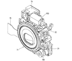
デジタルカメラ70は、ズームレンズ鏡筒71の上方に、該ズームレンズ鏡筒70に連動するズームファインダを備えている。図7及び図25に示すように、ズームファインダの光学系は、被写体側から順に対物窓81a、第1の可動変倍レンズ(被駆動部材)81b、第2の可動変倍レンズ(被駆動部材)81c、ミラー81d、固定レンズ81e、プリズム81f、接眼レンズ81g、接眼窓81hを有し、このうち対物窓81aと接眼窓81hはカメラボディ72に固定され、他の光学要素はファインダ支持枠82に支持されている。ファインダ支持枠82に支持される光学要素のうち、第1と第2の可動変倍レンズ81b、81cを除くものは、該ファインダ支持枠82の所定位置に固定されている。第1の可動変倍レンズ81bを支持する第1可動枠(被駆動部材)83と、第2の可動変倍レンズ81cを支持する第2可動枠(被駆動部材)84はそれぞれ、撮影光軸Z1及び鏡筒中心軸Z0と平行なガイドシャフト85、86によって移動可能に支持されており、第1と第2の可動変倍レンズ81b、81cの光軸Z3は、互いの相対位置に関わらず常に撮影光軸Z1及び鏡筒中心軸Z0と平行になっている。つまり、第1可動枠83と第1可動枠84は、撮影光軸Z1及及び鏡筒中心軸Z0と平行な方向へ移動可能である。第1可動枠83と第2可動枠84はそれぞれ、圧縮コイルばね87、88によって被写体側(前方)に付勢されている。ファインダ支持枠82にはさらに、光軸Z3(撮影光軸Z1及び鏡筒中心軸Z0)と平行な回転軸89を介して、円筒状のカムギヤ(駆動方向変換機構、円筒状カム)90が支持されている。
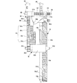
[Explanation of zoom finder]
The digital camera 70 includes a zoom finder that is linked to the zoom lens barrel 70 above the zoom lens barrel 71. As shown in FIGS. 7 and 25, the optical system of the zoom finder includes an objective window 81a, a first movable variable power lens (driven member) 81b, and a second movable variable power lens (driven member) in order from the subject side. ) 81c, a mirror 81d, a fixed lens 81e, a prism 81f, an eyepiece 81g, and an eyepiece window 81h, of which the objective window 81a and the eyepiece window 81h are fixed to the camera body 72, and the other optical elements are a finder support frame 82. It is supported by. Of the optical elements supported by the finder support frame 82, those excluding the first and second movable zoom lenses 81b and 81c are fixed to predetermined positions of the finder support frame 82. A first movable frame (driven member) 83 that supports the first movable zoom lens 81b and a second movable frame (driven member) 84 that supports the second movable zoom lens 81c are each a photographic optical axis. It is movably supported by guide shafts 85 and 86 parallel to Z1 and the barrel axis Z0, and the optical axes Z3 of the first and second movable variable power lenses 81b and 81c are independent of their relative positions. It is always parallel to the photographing optical axis Z1 and the lens barrel center axis Z0. That is, the first movable frame 83 and the first movable frame 84 are movable in a direction parallel to the photographing optical axis Z1 and the lens barrel center axis Z0. The first movable frame 83 and the second movable frame 84 are urged toward the subject (forward) by compression coil springs 87 and 88, respectively. The finder support frame 82 further supports a cylindrical cam gear (driving direction conversion mechanism, cylindrical cam) 90 via a rotating shaft 89 parallel to the optical axis Z3 (the photographing optical axis Z1 and the lens barrel center axis Z0). Have been.

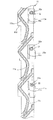
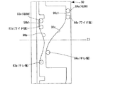
カムギヤ90は、軸方向の最前方にギヤ部90aを有し、その後方の外周面に第1カム面90bが形成され、該第1カム面90bの後方の外周面に第2カム面90cが形成されている。カムギヤ90は、圧縮コイルばね90dによって前方に押圧されてバックラッシュが除去されている。第1カム面90bに対しては、第1可動枠83に設けたフォロアピン83aが圧縮コイルばね87の付勢力によって押し付けられており、第2カム面90cに対しては、第2可動枠84に設けたフォロアピン84aが圧縮コイルばね88の付勢力によって押し付けられている。カムギヤ90が回転すると、第1カム面90b及び第2カム面90cの形状に従って第1可動枠83と第2可動枠84、すなわち第1と第2の可動変倍レンズ81b、81cが光軸方向に所定の軌跡で移動し、これにより撮影光学系に連動してファインダ光学系における変倍が行われる。図40は、展開した状態の第1カム面90b及び第2カム面90c上における、収納状態、ワイド端及びテレ端でのフォロアピン83a、84aの位置関係を示している。対物窓81aと接眼窓81hを除く以上のズームファインダの構成要素はファインダユニット80としてサブアッシされ、図26に示すように、固定ビス80aを用いて固定環22の上部に取り付けられる。   The cam gear 90 has a gear portion 90a at the forefront in the axial direction, a first cam surface 90b is formed on an outer peripheral surface behind the gear portion 90a, and a second cam surface 90c is formed on an outer peripheral surface behind the first cam surface 90b. Is formed. The cam gear 90 is pressed forward by the compression coil spring 90d to remove backlash. The follower pin 83a provided on the first movable frame 83 is pressed against the first cam surface 90b by the urging force of the compression coil spring 87, and is pressed against the second movable frame 84 against the second cam surface 90c. The provided follower pin 84 a is pressed by the urging force of the compression coil spring 88. When the cam gear 90 rotates, the first movable frame 83 and the second movable frame 84, that is, the first and second movable zoom lenses 81b and 81c move in the optical axis direction according to the shapes of the first cam surface 90b and the second cam surface 90c. Then, the finder optical system moves along a predetermined trajectory. FIG. 40 shows the positional relationship between the follower pins 83a and 84a in the stored state and the wide end and the tele end on the first cam surface 90b and the second cam surface 90c in the unfolded state. The components of the zoom finder other than the objective window 81a and the eyepiece window 81h are sub-assembled as a finder unit 80, and are attached to the upper portion of the fixed ring 22 using fixed screws 80a as shown in FIG.

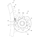
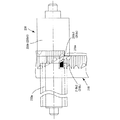
ズームファインダのカムギヤ90は、ヘリコイド環18のスパーギヤ部18cに噛合するギヤ部30aを有するファインダギヤ(回転伝達ギヤ、連動光学系駆動ギヤ)30と、該ファインダギヤ30の回転力を伝達する伝達ギヤ列91を介して駆動力を得ている。ファインダギヤ30は、軸線方向に位置を異ならせてギヤ部30aと回転規制筒(回転規制部)30bを有し、ギヤ部30aと回転規制筒30bから前後に回転軸30c、30dが突設されている。前方の回転軸30cは固定環22内の軸孔(不図示)に嵌合し、後方の回転軸30dはCCDホルダ21に形成した軸孔21bに嵌合している。こうして支持されたファインダギヤ30は、ヘリコイド環18の回転中心軸(鏡筒中心軸Z0)と平行な回転中心(回転軸30c、30d)によって回転可能であり、光軸方向には移動しない。伝達ギヤ列91は、複数の平ギヤ91a、91b、91c及び91dからなり、各平ギヤは、固定環22から撮影光軸Z1と平行に突設した複数のギヤ支持軸93によって回転可能に支持され、固定ビス92aを介して固定環22の前面に固定されるギヤ押さえ板92によって保持される。伝達ギヤ列91の各平ギヤ91aないし91dを固定環22の所定位置に取り付けると、図30ないし図32に示すように、各ギヤの噛合関係によってファインダギヤ30からカムギヤ90へと回転力が伝達されるようになる。図27ないし図29は、ファインダギヤ30、ファインダユニット80及び伝達ギヤ列91を全て取り付けた状態のズームレンズ鏡筒71である。   The cam gear 90 of the zoom finder includes a finder gear (rotation transmission gear, interlocking optical system driving gear) 30 having a gear portion 30a that meshes with the spur gear portion 18c of the helicoid ring 18, and a transmission gear that transmits the rotational force of the finder gear 30. The driving force is obtained via the row 91. The finder gear 30 has a gear portion 30a and a rotation restricting cylinder (rotation restricting portion) 30b at different positions in the axial direction, and has rotating shafts 30c and 30d protruding forward and backward from the gear portion 30a and the rotation restricting cylinder 30b. ing. The front rotation shaft 30c is fitted in a shaft hole (not shown) in the fixed ring 22, and the rear rotation shaft 30d is fitted in a shaft hole 21b formed in the CCD holder 21. The finder gear 30 thus supported is rotatable about a rotation center (rotation axes 30c, 30d) parallel to the rotation center axis (lens tube center axis Z0) of the helicoid ring 18, and does not move in the optical axis direction. The transmission gear train 91 is composed of a plurality of flat gears 91a, 91b, 91c and 91d, each of which is rotatably supported by a plurality of gear support shafts 93 projecting from the fixed ring 22 in parallel with the photographing optical axis Z1. Then, it is held by a gear pressing plate 92 fixed to the front surface of the fixed ring 22 via a fixing screw 92a. When the flat gears 91a to 91d of the transmission gear train 91 are attached to predetermined positions of the fixed ring 22, the rotational force is transmitted from the finder gear 30 to the cam gear 90 due to the meshing relationship of the gears, as shown in FIGS. Will be done. FIGS. 27 to 29 show the zoom lens barrel 71 with the finder gear 30, the finder unit 80, and the transmission gear train 91 all attached.

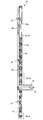
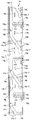
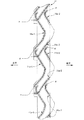
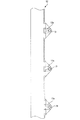
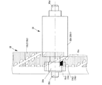
前述の通り、ヘリコイド環18は、収納状態からズーム領域に達するまでは固定環22及び直進移動環14に対して回転しながらその回転軸(鏡筒中心軸Z0)に沿って前方へ繰り出され、ズーム領域に達すると該回転軸(鏡筒中心軸Z0)方向への移動は行わずに定位置で回転のみ行うようになっている。図20ないし図24はこのヘリコイド環18の動作態様を示しており、図20及び図23が収納状態、図21及び図24がワイド端、図22がテレ端である。図23及び図24は、ファインダギヤ30とヘリコイド環18の関係を分かりやすくするために、固定環22を省略したものである。   As described above, the helicoid ring 18 is extended forward along its rotation axis (the lens barrel center axis Z0) while rotating with respect to the fixed ring 22 and the rectilinear moving ring 14 from the retracted state to the zoom region. When the zoom region is reached, only the rotation is performed at a fixed position without moving in the direction of the rotation axis (the lens barrel center axis Z0). 20 to 24 show the operation of the helicoid ring 18. FIGS. 20 and 23 show the retracted state, FIGS. 21 and 24 show the wide end, and FIG. 22 shows the tele end. 23 and 24 omits the fixed ring 22 in order to make the relationship between the finder gear 30 and the helicoid ring 18 easy to understand.

ファインダギヤ30は、収納状態からワイド端(ズーム領域)の直前までの光軸方向移動を伴うヘリコイド環18の回転時には回転せず、ワイド端からテレ端までのヘリコイド環18の定位置回転時に回転されるようになっている。すなわちファインダギヤ30のうち、スパーギヤ部18cに噛合して回転伝達を行うギヤ部30aは軸方向前端側の一部領域のみを占めており、図20及び図23の収納状態では、スパーギヤ部18cはギヤ部30よりも後方に位置しているので両ギヤ部は噛合していない。そして、図21及び図24のワイド端に達する直前でスパーギヤ部18cがギヤ部30の位置まで達して噛合される。以後は図22のテレ端に至るまで、ヘリコイド環18は光軸方向(図20ないし図24の左右方向)には移動しないので、スパーギヤ部18cとギヤ部30の噛合関係が維持される。   The finder gear 30 does not rotate during rotation of the helicoid ring 18 accompanied by movement in the optical axis direction from the stored state to immediately before the wide end (zoom area), but rotates during fixed position rotation of the helicoid ring 18 from the wide end to the telephoto end. It is supposed to be. That is, of the finder gear 30, the gear portion 30a that meshes with the spur gear portion 18c to transmit the rotation occupies only a part of the region in the front end side in the axial direction. In the storage state of FIGS. 20 and 23, the spur gear portion 18c is Since both gears are located behind the gear 30, both gears are not engaged. Then, immediately before reaching the wide end in FIGS. 21 and 24, the spur gear portion 18c reaches and meshes with the position of the gear portion 30. Thereafter, the helicoid ring 18 does not move in the optical axis direction (the left-right direction in FIGS. 20 to 24) until reaching the tele end in FIG. 22, so that the meshing relationship between the spur gear portion 18c and the gear portion 30 is maintained.

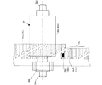
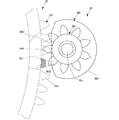
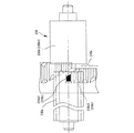
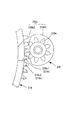
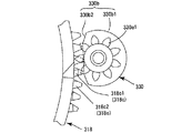
また、図37ないし図39から分かるように、ファインダギヤ30の回転規制筒30bは、ギヤ部30aよりも大径の不完全な円筒状をなす大径円筒部30b1と、該大径円筒部30b1の一部を略直線(平面)状に切り欠いた平面部(平面状外面部)30b2とからなる非円形(D字状)の断面形状を有しており、平面部30b2の形成領域では、回転規制筒30bよりも径方向の外方にギヤ部30aのギヤが突出している。平面部30b2は、ファインダギヤ30の回転軸線(30c、30d)と平行な直線を含む平面として形成されている。収納状態では、ファインダギヤ30は図37の角度位置にあって、直線状の平面部30b2がヘリコイド環18に対向している。この対向状態において平面部30b2はスパーギヤ部18cの歯先(外縁部、歯先円)に近接しており、ファインダギヤ30が回転しようとしても、平面部30b2がスパーギヤ部18cの外縁部に当て付いて回転することができない。   As can be seen from FIGS. 37 to 39, the rotation restricting cylinder 30b of the finder gear 30 includes a large-diameter cylindrical part 30b1 having an incomplete cylindrical shape having a larger diameter than the gear part 30a, and the large-diameter cylindrical part 30b1. Has a non-circular (D-shaped) cross-sectional shape consisting of a flat portion (flat outer surface portion) 30b2 in which a part of the flat portion is cut out in a substantially straight (planar) shape. In the formation region of the flat portion 30b2, The gear of the gear portion 30a protrudes radially outward from the rotation restricting cylinder 30b. The plane portion 30b2 is formed as a plane including a straight line parallel to the rotation axis (30c, 30d) of the finder gear 30. In the stored state, the finder gear 30 is at the angular position in FIG. 37, and the linear flat portion 30b2 faces the helicoid ring 18. In this facing state, the flat portion 30b2 is close to the tooth tip (outer edge portion, tip circle) of the spur gear portion 18c. Cannot rotate.

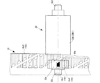
図24のように、ヘリコイド環18がスパーギヤ部18cをファインダギヤ30のギヤ部30aに噛合させるまで前進すると、該ヘリコイド環18は、スパーギヤ部18cを含んだ全体が回転規制筒30bよりも前方に位置する。この状態では、回転規制筒30bがヘリコイド環18のスパーギヤ部18cと重ならなくなるので、ファインダギヤ30はヘリコイド環18と共に回転可能になる。   As shown in FIG. 24, when the helicoid ring 18 moves forward until the spur gear portion 18c meshes with the gear portion 30a of the finder gear 30, the entire helicoid ring 18 including the spur gear portion 18c is located forward of the rotation restricting cylinder 30b. To position. In this state, the rotation restricting cylinder 30b does not overlap with the spur gear portion 18c of the helicoid ring 18, so that the finder gear 30 can rotate together with the helicoid ring 18.

なお、ヘリコイド環18には、スパーギヤ部18cの前方に該スパーギヤ部18cよりも外径方向への突出量の大きい3つの回転摺動突起18bが設けられているが、図23及び図24から分かるように、収納状態からワイド端までのヘリコイド環18の回転は、回転方向において一対の回転摺動突起18bの間にファインダギヤ30が位置するうちに完了するので、ヘリコイド環18の回転繰出の途中でファインダギヤ30と回転摺動突起18bが干渉することはない。スパーギヤ部18cとギヤ部30aが噛合した状態では、回転摺動突起18bは既にギヤ部30aよりも前方に位置しているので、以後は、ヘリコイド環18の回転量に関わらず、ファインダギヤ30と回転摺動突起18bが干渉することはない。   Note that the helicoid ring 18 is provided with three rotary sliding projections 18b which are larger in the outer diameter direction than the spur gear portion 18c in front of the spur gear portion 18c, as can be seen from FIGS. 23 and 24. As described above, since the rotation of the helicoid ring 18 from the stowed state to the wide end is completed while the finder gear 30 is positioned between the pair of rotary sliding protrusions 18b in the rotation direction, the rotation of the helicoid ring 18 is in the middle of rotation. Therefore, the finder gear 30 does not interfere with the rotary sliding projection 18b. When the spur gear portion 18c and the gear portion 30a are in mesh with each other, the rotation sliding protrusion 18b is already located forward of the gear portion 30a. The rotation sliding projection 18b does not interfere.

以上のように本実施形態では、回転しながら回転軸方向にも移動する回転進退と回転軸方向には移動しない定位置回転とを行うヘリコイド環18に対し、定位置回転時にのみスパーギヤ部18cと噛合する領域にファインダギヤ30のギヤ部30aを設け、さらに該ギヤ部30aの後方には断面非円形の回転規制筒30bを設け、ヘリコイド環18の回転進退時には該回転規制筒30bとスパーギヤ部18cとの当接によってファインダギヤ30の回転が規制されるようにした。これにより、撮影光学系が収納状態とズーム領域の間を移行するときはファインダギヤ30が回転せず、撮影光学系がワイド端とテレ端の間のズーム領域で駆動されるときのみファインダギヤ30が回転される。収納状態からズーム領域では、撮影光学系にズームファインダを動作させる必要がないので、換言すれば、ズームファインダを撮影光学系に連動させる必要があるときのみファインダギヤ30が回転するようになっている。   As described above, in the present embodiment, the spur gear portion 18c and the helicoid ring 18 that rotate and retreat while rotating and also move in the rotation axis direction and perform fixed position rotation without moving in the rotation axis direction are used only during the fixed position rotation. A gear portion 30a of the finder gear 30 is provided in an area where the finder gear 30 meshes, and a rotation restricting cylinder 30b having a non-circular cross section is provided behind the gear portion 30a. The rotation of the finder gear 30 is restricted by contact with the finder gear 30. Thus, the finder gear 30 does not rotate when the photographing optical system shifts between the retracted state and the zoom region, and only when the photographing optical system is driven in the zoom region between the wide end and the tele end. Is rotated. In the zoom range from the housed state, it is not necessary to operate the zoom finder in the photographing optical system. In other words, the finder gear 30 rotates only when it is necessary to link the zoom finder with the photographing optical system. .

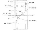
本実施形態との比較例として、ヘリコイド環18の回転時には常にファインダギヤ(30)が回転されるような態様を仮定する。この場合、ズームファインダを駆動する必要のない収納状態からの繰出段階でもファインダギヤ(30)が回転されるので、ファインダギヤ(30)からズームファインダの可動レンズ(81b、81c)までの駆動力伝達系の中で、可動変倍レンズ(81b、81c)をファインダギヤ(30)に連動させない空走区間を設けなければならない。図41は、この種の空走区間を設けたカムギヤ90′(実施形態のカムギヤ90に対応)を示しており、第1カム面90b′と第2カム面90c′はそれぞれ、カムギヤ90′が回転してもフォロアピン83a′、84a′をファインダ対物系の光軸Z3′方向に移動させないための長い周方向直線面90b1′、90c1′を有している。図40における本実施形態のカムギヤ90との比較から分かる通り、カムギヤ90′は第1カム面90b'と第2カム面90c′上に長い周方向直線面90b1′、90c1′を形成した分、残るズーム連動用のカム形成可能領域が短くなり、その影響でズーム用カムの傾斜が大きくなっている。カム面の傾斜が大きくなると、カムギヤ90′の所定回転角あたりの回転軸方向(ファインダ対物系の光軸Z3′方向)へのフォロアピン83a′、84a′の移動量が大きくなるので、該フォロアピン83a′、84a′に対する進退方向への移動精度を出すことが難しくなる。これを嫌ってズーム連動用のカムの傾斜をなだらかにすると、カムギヤ90′の外径サイズが増大して小型化が妨げられてしまう。これはカムギヤ90、90'のような円筒状のカムに限らず、平面状のカム板についても同様のことが言える。   As a comparative example with the present embodiment, it is assumed that the finder gear (30) is always rotated when the helicoid ring 18 rotates. In this case, since the finder gear (30) is rotated even in the extension stage from the housed state where it is not necessary to drive the zoom finder, the driving force is transmitted from the finder gear (30) to the movable lenses (81b, 81c) of the zoom finder. In the system, there must be provided an idle running section in which the movable zoom lenses (81b, 81c) are not linked to the finder gear (30). FIG. 41 shows a cam gear 90 ′ (corresponding to the cam gear 90 of the embodiment) provided with this kind of idle running section, and the first cam surface 90 b ′ and the second cam surface 90 c ′ have the cam gear 90 ′, respectively. Long circumferential straight surfaces 90b1 'and 90c1' are provided to prevent the follower pins 83a 'and 84a' from moving in the direction of the optical axis Z3 'of the finder objective system even when rotated. As can be seen from the comparison with the cam gear 90 of this embodiment in FIG. 40, the cam gear 90 'is formed by forming the long circumferential straight surfaces 90b1' and 90c1 'on the first cam surface 90b' and the second cam surface 90c '. The remaining area in which the cam for zoom interlock can be formed is shortened, and as a result, the inclination of the zoom cam is increased. When the inclination of the cam surface increases, the amount of movement of the follower pins 83a 'and 84a' in the direction of the rotation axis (in the direction of the optical axis Z3 'of the finder objective system) per predetermined rotation angle of the cam gear 90' increases. , 84a 'in the forward and backward directions. If the inclination of the cam for zoom interlocking is made gentle to avoid this, the outer diameter size of the cam gear 90 'increases, and miniaturization is hindered. This is not limited to cylindrical cams such as the cam gears 90 and 90 ', but the same can be said for a flat cam plate.

これに対し、ファインダギヤ30に不必要な回転を行わせないようにした本実施形態によれば、カムギヤ90では上記のような空走区間が実質的に不要であるため、第1カム面90b及び第2カム面90cのズーム連動用の有効カム長を十分に確保して無理のない(傾斜の小さい)カム軌跡を得つつ、カムギヤ90の外径サイズを小さく抑えることができる。つまり、ファインダ駆動系の小型化とファインダ光学系の高い精度での動作を両立させることが可能となった。なお、各ギヤ間のバックラッシュなどを考慮して、本実施形態では収納位置からの繰出時において、ズーム領域(ワイド端)に達する若干前のタイミングで敢えてスパーギヤ部18cにギヤ部30aを噛合させているため、各カム面90b及び90cには周方向直線面90b1及び90c1が形成されているが、その長さは図41の比較例におけるカムギヤ90′の周方向直線面90b1′及び90c1′に比べて遙かに短くて済む。   On the other hand, according to the present embodiment in which the finder gear 30 is not rotated unnecessarily, the cam gear 90 does not substantially need the idle running section as described above. In addition, the outer diameter size of the cam gear 90 can be suppressed small while obtaining a reasonable (small inclination) cam trajectory by sufficiently securing an effective cam length for zoom interlock of the second cam surface 90c. That is, it has become possible to achieve both miniaturization of the finder drive system and high-precision operation of the finder optical system. In consideration of the backlash between the gears and the like, in the present embodiment, the gear portion 30a is engaged with the spur gear portion 18c at a timing slightly before reaching the zoom region (wide end) at the time of extension from the storage position. Therefore, the circumferential surfaces 90b1 and 90c1 are formed on the respective cam surfaces 90b and 90c, and the length thereof is the same as the circumferential linear surfaces 90b1 'and 90c1' of the cam gear 90 'in the comparative example of FIG. It is much shorter than this.

本実施形態ではさらに、ファインダギヤ30のギヤ部30aがヘリコイド環18のスパーギヤ部18cに対して円滑に噛合されるように、スパーギヤ部18cの形状に特徴を有している。すなわち、スパーギヤ部18cには、通常のギヤ山18c2に比べてヘリコイド環18からの突出量が小さい(低い)低ギヤ山18c1が設けられている。   The present embodiment is further characterized in the shape of the spur gear portion 18c such that the gear portion 30a of the finder gear 30 is smoothly meshed with the spur gear portion 18c of the helicoid ring 18. That is, the spur gear portion 18c is provided with the low gear ridge 18c1 having a smaller (lower) protrusion amount from the helicoid ring 18 than the normal gear ridge 18c2.

図33ないし図36は、図23の収納状態から図24のワイド端に達する間のギヤ部30aとスパーギヤ部18cの位置関係を時系列順に示したものである。図33は、収納状態からワイド端に向けてヘリコイド環18が回転繰出を行っていき、スパーギヤ部18cがギヤ部30aに接近した状態を示している。   FIGS. 33 to 36 show the positional relationship between the gear portion 30a and the spur gear portion 18c in the time series from the storage state in FIG. 23 to the wide end in FIG. FIG. 33 shows a state in which the helicoid ring 18 rotates and extends from the stored state toward the wide end, and the spur gear portion 18c approaches the gear portion 30a.

図34は、スパーギヤ部18cがギヤ部30aにさらに接近した状態を示している。同図に示すように、スパーギヤ部18cにおいてはまず低ギヤ山18c1がギヤ部30aに接近する。この状態をファインダギヤ30の前面側から示したものが図37であり、同図から理解されるように、この段階では低ギヤ山18c1はギヤ部30aには接触していない。他の通常ギヤ山18c2は、ギヤ部30aに対して低ギヤ山18c1よりも離間した位置にあり、低ギヤ山18c1と同様にギヤ部30aに噛合していない。また、収納状態からワイド端へのヘリコイド環18の回転進行方向(図34の上方)において、低ギヤ山18c1に隣接する一部領域にはギヤ山が形成されていない。よって、図34及び図37の状態ではギヤ部30aに対してスパーギヤ部18cが噛合しておらず、ファインダギヤ30には回転力が伝達されない。なお、図34の状態では、スパーギヤ部18cの一部が依然として回転規制筒30bの切欠部30b2に対向しているので、仮にファインダギヤ30に回転力が作用しても実際にはファインダギヤ30は回転されない。   FIG. 34 shows a state in which the spur gear portion 18c has come closer to the gear portion 30a. As shown in the drawing, in the spur gear portion 18c, the low gear ridge 18c1 first approaches the gear portion 30a. FIG. 37 shows this state from the front side of the finder gear 30. As can be understood from FIG. 37, at this stage, the low gear ridge 18c1 is not in contact with the gear portion 30a. The other normal gear ridge 18c2 is located at a position more distant from the gear portion 30a than the low gear ridge 18c1, and does not mesh with the gear portion 30a like the low gear ridge 18c1. Further, no gear ridge is formed in a part of the region adjacent to the low gear ridge 18c1 in the rotation traveling direction of the helicoid ring 18 from the stored state to the wide end (upper part in FIG. 34). 34 and 37, the spur gear portion 18c is not meshed with the gear portion 30a, and no rotational force is transmitted to the finder gear 30. In the state of FIG. 34, since a part of the spur gear portion 18c still faces the cutout portion 30b2 of the rotation restricting cylinder 30b, even if a rotational force acts on the finder gear 30, the finder gear 30 is actually Not rotated.

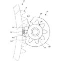
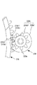
ヘリコイド環18が繰出方向への回転を続け、低ギヤ山18c1が図35の位置まで達すると、図38のように低ギヤ山18c1がギヤ部30aの一つのギヤ歯30a1に接触してヘリコイド環18の進行方向へ押し込み、ファインダギヤ30の回転が開始される。   When the helicoid ring 18 continues to rotate in the extending direction and the low gear ridge 18c1 reaches the position in FIG. 35, the low gear ridge 18c1 contacts one gear tooth 30a1 of the gear portion 30a as shown in FIG. 18 in the traveling direction, and the rotation of the finder gear 30 is started.

ヘリコイド環18がさらに繰出方向に回転すると、低ギヤ山18c1に隣接する通常ギヤ山18c2が続くギヤ歯30a2を押し込み、ファインダギヤ30の回転が継続される。これ以降、スパーギヤ部18cは、複数の通常ギヤ山18c2が順次ファインダギヤ30のギヤ部30aに噛合して回転を伝え、カムギヤ90へ回転力が伝達される。図24に示すように、ヘリコイド環18がワイド端に達した時点では、低ギヤ山18c1は既にファインダギヤ30のギヤ部30aとの噛合位置を通過しており、ワイド端からテレ端までのズーム領域で低ギヤ山18c1が用いられることはない。   When the helicoid ring 18 further rotates in the extending direction, the gear teeth 30a2 on which the normal gear ridge 18c2 adjacent to the low gear ridge 18c1 is pushed, and the rotation of the finder gear 30 is continued. Thereafter, in the spur gear portion 18 c, the plurality of normal gear ridges 18 c 2 sequentially mesh with the gear portion 30 a of the finder gear 30 to transmit rotation, and the rotational force is transmitted to the cam gear 90. As shown in FIG. 24, when the helicoid ring 18 reaches the wide end, the low gear ridge 18c1 has already passed through the meshing position with the gear portion 30a of the finder gear 30, and the zoom from the wide end to the telephoto end has been completed. The low gear ridge 18c1 is not used in the region.

このように、スパーギヤ部18cにおいてファインダギヤ30のギヤ部30aに最初に噛合する部分を、他のギヤ山よりも低い低ギヤ山18c1とすることにより、ギヤの噛合開始時に確実に噛合させることができる。すなわち、高いギヤ山同士であると、ギヤ山の相対角度が離れた状態で互いの歯先が近接して噛合に失敗(空振り)するおそれがある。これに対し、低ギヤ山18c1は、相手側のギヤ山(ファインダギヤ30のギヤ部30a)に対して、相対角度が略一致する状態でなければ係合しないので、噛合に失敗する(空振りする)おそれがない。また、低ギヤ山18c1では、ギヤ噛合開始時の衝撃が抑制される。その結果、ファインダギヤ30を含めたズームファインダ駆動系の動作を円滑に開始させることができ、静音性も向上する。   As described above, by setting the portion of the spur gear portion 18c that first meshes with the gear portion 30a of the finder gear 30 as the low gear mountain 18c1 lower than the other gear mountains, it is possible to surely mesh at the start of gear meshing. it can. That is, if the gear ridges are high, the tooth tips of the gear ridges may be close to each other in a state where the relative angles of the gear ridges are apart from each other, and the meshing may fail (missing). On the other hand, the low gear ridge 18c1 does not engage with the counterpart gear ridge (the gear portion 30a of the finder gear 30) unless the relative angles are substantially equal to each other, so that the meshing fails (missing). There is no fear. Further, at the low gear ridge 18c1, an impact at the start of gear engagement is suppressed. As a result, the operation of the zoom finder drive system including the finder gear 30 can be started smoothly, and the quietness is also improved.

以上では収納状態からズーム領域への繰出時に関して説明したが、ズーム領域から収納方向への動作においても繰出時と同様の作用効果が得られることは言うまでもない。   In the above, the description has been given of the case of extending from the stored state to the zoom region. However, it is needless to say that the same operation and effect as in the case of extending can be obtained in the operation from the zoom region to the storage direction.

以上のように本発明を適用した上記実施形態では、ファインダギヤ30にギヤ部30aと回転規制筒30bを設け、収納状態から撮影状態(ズーム領域)までは、ヘリコイド環18の環状ギヤ18cに回転規制筒30bを対向(接触)させてファインダギヤ30の回転を規制し、撮影状態で環状ギヤ18cとギヤ部30aが噛合するようにしたので、ファインダギヤ30は、ファインダ光学系を撮影光学系に連動させる必要があるとき(撮影状態)でのみ回転される。つまり、ヘリコイド環18の回転をファインダ光学系側に伝達させない空走区間をカムギヤ90に設ける必要がなく、カムギヤ90を小型化することができる。別言すれば、小型なカムギヤ90であっても、第1可動枠83や第2可動枠84を精度よく移動させることが可能なカム面90b、90cが得られる。   As described above, in the above embodiment to which the present invention is applied, the finder gear 30 is provided with the gear portion 30a and the rotation restricting cylinder 30b, and rotates from the retracted state to the photographing state (zoom area) by the rotation of the annular gear 18c of the helicoid ring 18. The rotation of the finder gear 30 is regulated by opposing (contacting) the regulating cylinder 30b, so that the annular gear 18c and the gear portion 30a mesh with each other in the photographing state. Therefore, the finder gear 30 changes the finder optical system to the photographing optical system. It is rotated only when it is necessary to link (shooting state). That is, it is not necessary to provide the cam gear 90 with an idle running section in which the rotation of the helicoid ring 18 is not transmitted to the finder optical system side, and the cam gear 90 can be downsized. In other words, even with the small cam gear 90, the cam surfaces 90b and 90c capable of accurately moving the first movable frame 83 and the second movable frame 84 can be obtained.

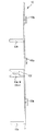
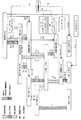
図42ないし図47は本発明の第2の実施形態を示す。この実施形態では、撮影状態においてもヘリコイド環218が定位置回転を行わずに、回転しながら軸方向に進退する点が先の実施形態と異なる。すなわち、ヘリコイド環218に形成した雄ヘリコイド218aは、収納状態から撮影状態に繰り出された後も対応する雌ヘリコイド(不図示)との噛合を続けるように構成されている。ファインダギヤ230の回転規制筒230b(大径円筒部230b1、平面部230b2)については、先の実施形態と同様の構成である。   42 to 47 show a second embodiment of the present invention. This embodiment differs from the previous embodiment in that the helicoid ring 218 does not rotate at a fixed position and moves in the axial direction while rotating, even in the shooting state. In other words, the male helicoid 218a formed on the helicoid ring 218 is configured to continue meshing with the corresponding female helicoid (not shown) even after the male helicoid 218a is extended from the stored state to the photographing state. The rotation restricting cylinder 230b (large-diameter cylindrical part 230b1, flat part 230b2) of the finder gear 230 has the same configuration as that of the previous embodiment.

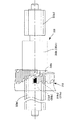
図42及び図45は、第2実施形態において収納状態から撮影状態に切り換わる途中の状態を示しており、ファインダギヤ230の回転規制筒230bの平面部230b2が、ヘリコイド環218のスパーギヤ部218cに対向している。このとき平面部230b2はスパーギヤ部218cの歯先(外縁部、歯先円)に近接しており、ファインダギヤ230が回転しようとしても、平面部230b2がスパーギヤ部218cの外縁部に当て付いて回転することができない。   FIGS. 42 and 45 show a state in the middle of switching from the stowed state to the photographing state in the second embodiment. The flat portion 230b2 of the rotation restricting cylinder 230b of the finder gear 230 is attached to the spur gear portion 218c of the helicoid ring 218. They are facing each other. At this time, the flat portion 230b2 is close to the tip (outer edge portion, tip circle) of the spur gear portion 218c, and even if the finder gear 230 tries to rotate, the flat portion 230b2 comes into contact with the outer edge portion of the spur gear portion 218c and rotates. Can not do it.

図43及び図46は、収納状態から撮影状態に切り換わる時点(直前)の状態を示しており、該ヘリコイド環218のスパーギヤ部218cが回転規制筒230bよりも前方に移動されるので、ファインダギヤ230はヘリコイド環218と共に回転可能になる。そして、ギヤ部230aがスパーギヤ部218cに噛合してヘリコイド環218の回転がファインダギヤ230に伝達される。このとき、ギヤ部230aは最初に低ギヤ山218c1に対して噛合し、次に通常のギヤ山218c2に噛合する。低ギヤ山218c1の機能は先の実施形態と同様である。   FIGS. 43 and 46 show the state at the time (immediately before) switching from the storage state to the photographing state. Since the spur gear portion 218c of the helicoid ring 218 is moved forward of the rotation restricting cylinder 230b, the finder gear is shown. 230 can rotate with helicoid ring 218. Then, the gear portion 230a meshes with the spur gear portion 218c, and the rotation of the helicoid ring 218 is transmitted to the finder gear 230. At this time, the gear portion 230a first meshes with the low gear mountain 218c1, and then meshes with the normal gear mountain 218c2. The function of the low gear crest 218c1 is the same as in the previous embodiment.

図44及び図47は、撮影状態(ズーム領域)の途中の状態を示している。図44に示すように、本実施形態では撮影状態になってからもヘリコイド環218は光軸方向前方(図中の左方)に向けて回転進退している(その軌跡を矢印Hで示す)。このヘリコイド環218の前方への移動は、ファインダギヤ230の回転規制筒230bから離れる方向の移動であるから、撮影状態では平面部230b2がスパーギヤ部218cに接触することはなく、ファインダギヤ230がヘリコイド環218に連動して回転される。ファインダギヤ230のギヤ部230aは、ヘリコイド環218が軸方向に進退してもスパーギヤ部218cとの噛合を維持することができるように、先の実施形態のものよりも軸方向に長く形成されている。   FIGS. 44 and 47 show a state in the middle of a shooting state (zoom area). As shown in FIG. 44, in the present embodiment, the helicoid ring 218 is rotated forward and backward (leftward in the drawing) in the optical axis direction even after the shooting state (the trajectory is indicated by an arrow H). . The forward movement of the helicoid ring 218 is a movement in a direction away from the rotation restricting cylinder 230b of the finder gear 230, so that the plane portion 230b2 does not contact the spur gear portion 218c in the photographing state, and the finder gear 230 is It is rotated in conjunction with the ring 218. The gear portion 230a of the finder gear 230 is formed to be longer in the axial direction than that of the previous embodiment so that the meshing with the spur gear portion 218c can be maintained even if the helicoid ring 218 advances and retreats in the axial direction. I have.

撮影状態から収納状態に戻るときは、以上とは逆にズーム領域(ワイド端)を越えた時点で平面部230b2がスパーギヤ部218cに対向し、以降はファインダギヤ230の回転が規制される。   When returning from the photographing state to the housed state, the plane portion 230b2 faces the spur gear portion 218c when the zoom region (wide end) is exceeded, and the rotation of the finder gear 230 is restricted thereafter.

このように、ズーム領域でヘリコイド環が回転しながら回転軸方向に進退するタイプのズームレンズカメラにも適用が可能である。つまり、本発明においては回転環が定位置回転を行わない(回転進退のみを行う)態様とすることも可能である。   As described above, the present invention is also applicable to a zoom lens camera of a type in which the helicoid ring rotates in the zoom region and moves back and forth in the rotation axis direction. That is, in the present invention, it is also possible to adopt a mode in which the rotating ring does not rotate at the fixed position (only performs the rotational movement).

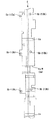
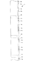
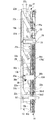
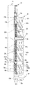
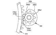
図48ないし図53は本発明の第3の実施形態を示す。この実施形態は、ファインダギヤ330が、回転規制筒330bを挟んで回転軸方向の前後に2つのギヤ部330a1、330a2を備えることに特徴がある。回転規制筒330bにおける大径円筒部330b1や平面部330b2は、先の各実施形態と同様の機能を有する。また、ヘリコイド環318における雄ヘリコイド318a、スパーギヤ部318c、低ギヤ山318c1、通常ギヤ山318c2などの形状や機能は、第2実施形態と共通する。   48 to 53 show a third embodiment of the present invention. This embodiment is characterized in that the finder gear 330 is provided with two gear portions 330a1 and 330a2 before and after in the direction of the rotation axis across the rotation regulating cylinder 330b. The large-diameter cylindrical portion 330b1 and the flat portion 330b2 in the rotation restricting cylinder 330b have the same functions as those in the above embodiments. The shapes and functions of the male helicoid 318a, the spur gear portion 318c, the low gear ridge 318c1, the normal gear ridge 318c2, and the like in the helicoid ring 318 are the same as those in the second embodiment.

図48ないし図50、及び図51ないし図53は、第2実施形態の図42ないし図44、及び図45ないし図47の同様の時間的推移を表している。重複による煩雑さを避けるため詳細な説明は省略するが、図48及び図51の状態ではファインダギヤ330の回転が規制され、図49及び図52の状態でギヤ部330a1がスパーギヤ部318cに噛合して該回転が可能になり、図50及び図53はヘリコイド環318に連動してファインダギヤ330が所定角度回転された状態を示している。ヘリコイド環318に逆方向の回転を与えると、図48及び図51の状態で再びファインダギヤ330の回転が規制される。本実施形態ではさらに、ヘリコイド環318を図48の位置よりも同図右手方向へ回転進退させたときに、回転規制筒330b(平面部330b2)の軸方向長さを越える移動量が与えられると、スパーギヤ部318cが別のギヤ部330a2に噛合して、ファインダギヤ330が再びヘリコイド環318に連動して回転されるようになる。つまり、ヘリコイド環318の一方向の回転進退において、ファインダギヤ330が連動回転される位相が2度現れることになる。   FIGS. 48 to 50 and FIGS. 51 to 53 show similar temporal transitions of FIGS. 42 to 44 and FIGS. 45 to 47 of the second embodiment. 48 and 51, the rotation of the finder gear 330 is restricted, and the gear 330a1 meshes with the spur gear 318c in the states of FIGS. 49 and 52. 50 and 53 show a state in which the finder gear 330 is rotated by a predetermined angle in conjunction with the helicoid ring 318. When the helicoid ring 318 is rotated in the opposite direction, the rotation of the finder gear 330 is regulated again in the state shown in FIGS. Further, in this embodiment, when the helicoid ring 318 is rotated forward and backward from the position in FIG. 48 to the right in FIG. 48, if a movement amount exceeding the axial length of the rotation restricting cylinder 330b (the flat portion 330b2) is given. The spur gear portion 318c meshes with another gear portion 330a2, and the finder gear 330 is rotated again in conjunction with the helicoid ring 318. In other words, the phase in which the finder gear 330 is interlockedly rotated appears twice in the rotation of the helicoid ring 318 in one direction.

このように、本発明においては、回転伝達ギヤが回転環に連動して回転する状態と回転規制される状態とを、回転伝達ギヤにおけるギヤ部と回転規制部の数や配置によって任意に変化させることができる。以上の例では2つのギヤ部330a1、330a2が1つの回転規制筒330bを挟むようにしたが、これと反対に回転規制筒(回転規制部)を2つ設けてその間にギヤ部を設けてもよい。この場合、回転が伝達される領域の両側2箇所が回転非伝達領域になるので、例えば撮影状態(ズーム域)を挟んで収納状態と分解状態とに切り換わるタイプのカメラにおいて、収納状態に加えて分解状態でも回転伝達を遮断するように適用することができる。さらに、回転軸方向におけるギヤ部と回転規制部の数をこれよりも増やすことも可能であり、ギヤ部と回転規制部をそれぞれ複数設けてもよい。この場合、回転軸方向においてギヤ部と回転規制部が交互に現れるように配置すればよい。   Thus, in the present invention, the state in which the rotation transmitting gear rotates in conjunction with the rotating ring and the state in which the rotation is restricted are arbitrarily changed by the number and arrangement of the gear portion and the rotation restricting portion in the rotation transmitting gear. be able to. In the above example, the two gear portions 330a1 and 330a2 sandwich one rotation regulating cylinder 330b. However, on the contrary, two rotation regulating cylinders (rotation regulating portions) may be provided and the gear portion may be provided therebetween. Good. In this case, two portions on both sides of the region to which rotation is transmitted are rotation non-transmission regions. Therefore, for example, in a camera of a type that switches between a stored state and a disassembled state across a shooting state (zoom area), in addition to the stored state, Therefore, the present invention can be applied to block rotation transmission even in a disassembled state. Further, the number of the gear portions and the rotation restricting portions in the rotation axis direction can be further increased, and a plurality of the gear portions and the rotation restricting portions may be provided. In this case, the gear portion and the rotation restricting portion may be arranged so as to appear alternately in the rotation axis direction.

また、第3の実施形態では、ヘリコイド環318は第2実施形態と同様に定位置回転を行わない(常に回転進退する)ものとしたが、例えば、スパーギヤ部318cがギヤ部330a1または(及び)ギヤ部330a2に噛合するときに、ヘリコイド環318が第1の実施形態と同様に軸方向への移動を行わずに定位置回転を行うように構成することもできる。   Further, in the third embodiment, the helicoid ring 318 does not perform the fixed position rotation (always rotates and retreats) as in the second embodiment, but, for example, the spur gear portion 318c is replaced with the gear portion 330a1 or (and). When meshing with the gear 330a2, the helicoid ring 318 may be configured to perform fixed-position rotation without moving in the axial direction as in the first embodiment.

以上、図示実施形態に基づき本発明を説明したが、本発明は実施形態に限定されるものではない。図示実施形態では撮影光学系に連動させる駆動対象はズームファインダであるが、撮影光学系に連動して照射角が変化するズームストロボの駆動系としても本発明は適用可能である。さらに本発明は、回転環の特定の回転位相でのみ回転力を取り出して伝達するような回転伝達機構であれば、実施形態のようなズームレンズカメラに限らず様々な機器に適用することができる。   As described above, the present invention has been described based on the illustrated embodiments, but the present invention is not limited to the embodiments. In the illustrated embodiment, the driving object linked to the photographing optical system is a zoom finder, but the present invention is also applicable to a driving system of a zoom strobe whose irradiation angle changes in conjunction with the photographing optical system. Further, the present invention can be applied not only to the zoom lens camera as in the embodiment but also to various devices as long as it is a rotation transmission mechanism that extracts and transmits a rotational force only at a specific rotational phase of the rotating ring. .

また、実施形態では回転環であるヘリコイド環18が回転軸方向に可動で、ヘリコイド環18の回転を受けるファインダギヤ30は、回転軸方向に移動しない定位置回転部材であるが、この両部材において、少なくともファインダギヤ30の回転軸方向成分を含む方向の相対移動が生じるのであれば、いずれを可動部材としてもよい。例えば、ヘリコイド環18を定位置回転のみ行う回転環とし、代わりにファインダギヤ30を回転軸方向へ移動させてもよい。あるいは、ヘリコイド環18とファインダギヤ30の両方を回転軸方向へ移動可能としてもよい。   In the embodiment, the finder gear 30 that is movable in the rotation axis direction and the finder gear 30 that is rotated by the helicoid ring 18 is a fixed position rotation member that does not move in the rotation axis direction. Any of the movable members may be used as long as the relative movement of the finder gear 30 at least in the direction including the rotational axis component occurs. For example, the helicoid ring 18 may be a rotating ring that performs only fixed position rotation, and the finder gear 30 may be moved in the direction of the rotating shaft instead. Alternatively, both the helicoid ring 18 and the finder gear 30 may be movable in the rotation axis direction.

また、実施形態では平面部30b2によってファインダギヤ30の回転規制を行っているが、このような平面に限らない別な形状の回転規制部を採用することも可能である。   Further, in the embodiment, the rotation of the finder gear 30 is restricted by the flat portion 30b2, but it is also possible to adopt a rotation restricting portion of another shape which is not limited to such a flat surface.

また本発明は、回転環と被駆動部材の間に設ける伝動機構に関しても、実施形態とは異なる形態とすることができる。例えば、被駆動部材が直進移動を行う場合、回転環の回転力を直進方向の移動力に変換させるために、上記実施形態で用いた円筒状のカムに代えて、ラックピニオン機構によって平面的に移動するカム板などを用いることもできる。   In the present invention, a transmission mechanism provided between the rotating ring and the driven member may be configured differently from the embodiment. For example, when the driven member makes a straight movement, in order to convert the rotating force of the rotating ring into a moving force in the straight direction, instead of the cylindrical cam used in the above-described embodiment, the rack and pinion mechanism is used to convert the rotating force into a planar shape. A moving cam plate or the like can also be used.

また、被駆動部材の駆動態様も、実施形態のような直進移動に限定されない。例えば、被駆動部材は回転部材であってもよい。
Further, the driving mode of the driven member is not limited to the straight traveling movement as in the embodiment. For example, the driven member may be a rotating member.

本発明の回転伝達機構を適用したズームレンズ鏡筒の分解斜視図である。FIG. 2 is an exploded perspective view of a zoom lens barrel to which the rotation transmission mechanism of the present invention is applied. 図1のズームレンズ鏡筒における、第1レンズ群の支持機構に関する要素の分解斜視図である。FIG. 2 is an exploded perspective view of elements related to a support mechanism of a first lens group in the zoom lens barrel in FIG. 1. 図1のズームレンズ鏡筒における、第2レンズ群の支持機構に関する要素の分解斜視図である。FIG. 2 is an exploded perspective view of elements related to a support mechanism of a second lens group in the zoom lens barrel in FIG. 1. 図1のズームレンズ鏡筒における、固定環から第3外筒までの繰出機構に関する要素の分解斜視図である。FIG. 2 is an exploded perspective view of elements related to a feeding mechanism from a fixed ring to a third outer cylinder in the zoom lens barrel in FIG. 1. 図1のズームレンズ鏡筒に、ズームモータとファインダユニットを加えた完成状態の斜視図である。FIG. 2 is a perspective view of a completed state in which a zoom motor and a finder unit are added to the zoom lens barrel of FIG. 1. 本発明を適用したズームレンズ鏡筒を搭載したカメラの、ワイド端とテレ端の使用状態を示す縦断面図であるFIG. 2 is a longitudinal sectional view showing a use state of a camera equipped with a zoom lens barrel to which the present invention is applied at a wide end and a tele end. 同カメラの鏡筒収納状態の縦断面図である。FIG. 3 is a longitudinal sectional view of the camera in a lens barrel stored state. 固定環の展開平面図である。FIG. 4 is a developed plan view of a fixed ring. ヘリコイド環の展開平面図である。FIG. 3 is a developed plan view of a helicoid ring. ヘリコイド環の内周面側の構成要素を透視して示す展開平面図である。FIG. 3 is an exploded plan view showing components on the inner peripheral surface side of the helicoid ring in a see-through manner. 第3外筒の展開平面図である。It is a development top view of the 3rd outer cylinder. 直進案内環の展開平面図である。FIG. 4 is a developed plan view of a straight guide ring. カム環の展開平面図である。FIG. 4 is a developed plan view of a cam ring. カム環の内周面側の2群案内カム溝を透視して示す展開平面図である。FIG. 7 is an exploded plan view showing the second group guide cam groove on the inner peripheral surface side of the cam ring in a see-through manner. 直進案内環の展開平面図である。FIG. 4 is a developed plan view of a straight guide ring. 2群レンズ移動枠の展開平面図である。FIG. 5 is a developed plan view of a second group lens moving frame. 第2外筒の展開平面図である。It is a development top view of a 2nd outer cylinder. 第1外筒の展開平面図である。FIG. 4 is a developed plan view of a first outer cylinder. 本実施形態のズームレンズ鏡筒の主要な構成要素の動作関係を概念的に示す図である。FIG. 3 is a diagram conceptually illustrating an operation relationship of main components of the zoom lens barrel according to the embodiment. 鏡筒収納状態におけるヘリコイド環、第3外筒及び固定環の関係を示す展開平面図である。FIG. 10 is a developed plan view showing a relationship between a helicoid ring, a third outer cylinder, and a fixed ring in a lens barrel stored state. ワイド端におけるヘリコイド環、第3外筒及び固定環の関係を示す展開平面図である。FIG. 9 is a developed plan view showing a relationship between a helicoid ring, a third outer cylinder, and a fixed ring at a wide end. テレ端におけるヘリコイド環、第3外筒及び固定環の関係を示す展開平面図である。FIG. 10 is a developed plan view showing a relationship between a helicoid ring, a third outer cylinder, and a fixed ring at a telephoto end. 図20から固定環を省略した展開平面図である。FIG. 21 is a developed plan view omitting a fixed ring from FIG. 20. 図21から固定環を省略した展開平面図である。FIG. 22 is a developed plan view in which a fixed ring is omitted from FIG. 21. ファインダユニットの分解斜視図である。It is an exploded perspective view of a finder unit. ファインダユニットと伝達ギヤ列をズームレンズ鏡筒に取り付ける工程を示す前方からの斜視図である。FIG. 6 is a front perspective view showing a step of attaching a finder unit and a transmission gear train to a zoom lens barrel. ファインダユニット及び伝達ギヤ列の取り付け後のズームレンズ鏡筒の前方斜視図である。FIG. 4 is a front perspective view of the zoom lens barrel after the finder unit and the transmission gear train are attached. 同ズームレンズ鏡筒の側面図である。FIG. 3 is a side view of the zoom lens barrel. 同ズームレンズ鏡筒の後方斜視図である。FIG. 3 is a rear perspective view of the zoom lens barrel. ヘリコイド環からファインダ光学系の可動変倍レンズまでの動力伝達系を取り出して示す前方斜視図である。It is a front perspective view which extracts and shows the power transmission system from a helicoid ring to the movable variable power lens of a finder optical system. 同動力伝達系の正面図である。It is a front view of the same power transmission system. 同動力伝達系の側面図である。It is a side view of the same power transmission system. 図23の収納状態から図24のワイド端に至る途中のファインダギヤとヘリコイド環の位置関係を示す展開平面図である。FIG. 24 is an exploded plan view showing the positional relationship between the finder gear and the helicoid ring on the way from the housed state in FIG. 23 to the wide end in FIG. 24. 図33に続く状態の同展開平面図である。FIG. 34 is a developed plan view showing a state following FIG. 33. 図34に続く状態の同展開平面図である。FIG. 35 is a developed plan view showing a state following FIG. 34. 図35に続く状態の同展開平面図である。FIG. 36 is an exploded plan view of the state following FIG. 35. 図34の状態をファインダギヤの正面側から見た図である。FIG. 35 is a view of the state of FIG. 34 as viewed from the front side of the finder gear. 図35の状態をファインダギヤの正面側から見た図である。FIG. 36 is a view of the state of FIG. 35 as viewed from the front side of the finder gear. 図36の状態をファインダギヤの正面側から見た図である。FIG. 37 is a view of the state of FIG. 36 as viewed from the front side of the finder gear. ファインダ光学系のカムギヤの展開平面図である。FIG. 4 is a developed plan view of a cam gear of the finder optical system. 本発明と比較するための、空走区間を有する従来のカムギヤの展開平面図である。FIG. 4 is an exploded plan view of a conventional cam gear having an idle running section for comparison with the present invention. 本発明の第2の実施形態において、ヘリコイド環に対するファインダギヤの連動回転が規制されている状態の両者の位置関係を示す展開平面図である。FIG. 10 is a developed plan view showing a positional relationship between the finder gear and the helicoid ring in a state where the finder gear is interlocked with the helicoid ring in the second embodiment. 図42に続き、ファインダギヤがヘリコイド環に連動して回転可能になった状態の展開平面図である。FIG. 43 is a developed plan view showing a state where the finder gear is rotatable in conjunction with the helicoid ring, following FIG. 42. 図43に続き、ファインダギヤがヘリコイド環に連動して所定角回転された状態の展開平面図である。FIG. 44 is a developed plan view showing a state where the finder gear has been rotated by a predetermined angle in conjunction with the helicoid ring, following FIG. 43; 図42の状態をファインダギヤの正面側から見た図である。FIG. 43 is a view of the state of FIG. 42 as viewed from the front side of the finder gear. 図43の状態をファインダギヤの正面側から見た図である。FIG. 44 is a view of the state of FIG. 43 as viewed from the front side of the finder gear. 図44の状態をファインダギヤの正面側から見た図である。FIG. 45 is a view of the state of FIG. 44 as viewed from the front side of the finder gear. 本発明の第3の実施形態において、ヘリコイド環に対するファインダギヤの連動回転が規制されている状態の両者の位置関係を示す展開平面図である。FIG. 14 is a developed plan view showing a positional relationship between the finder gear and the helicoid ring in a state where the finder gear is interlocked with the helicoid ring in the third embodiment. 図48に続き、ファインダギヤがヘリコイド環に連動して回転可能になった状態の展開平面図である。FIG. 49 is a developed plan view showing a state where the finder gear is rotatable in conjunction with the helicoid ring, following FIG. 48; 図49に続き、ファインダギヤがヘリコイド環に連動して所定角回転された状態の展開平面図である。FIG. 50 is a developed plan view showing a state where the finder gear has been rotated by a predetermined angle in conjunction with the helicoid ring, following FIG. 49; 図48の状態をファインダギヤの正面側から見た図である。FIG. 50 is a view of the state of FIG. 48 as viewed from the front side of the finder gear. 図49の状態をファインダギヤの正面側から見た図である。FIG. 50 is a view of the state of FIG. 49 as viewed from the front side of the finder gear. 図50の状態をファインダギヤの正面側から見た図である。FIG. 51 is a view of the state of FIG. 50 as viewed from the front side of the finder gear.

符号の説明Explanation of reference numerals

A 絞り
LG1 第1レンズ群
LG2 第2レンズ群
LG3 第3レンズ群
LG4 ローパスフィルタ
S シャッタ
Z0 鏡筒中心軸(回転環の回転軸)
Z1 撮影光軸
Z2 退避光軸
Z3 ファインダ対物系の光軸
1 1群レンズ枠
1a 雄調整ねじ
2 1群調整環
2a 雌調整ねじ
2b ガイド突起
2c 係合爪
3 1群抜止環
3a ばね受け部
6 2群レンズ枠
8 2群レンズ移動枠
8a 直進案内溝
8b 2群用カムフォロア
8b-1 前方カムフォロア
8b-2 後方カムフォロア
10 2群直進案内環
10a 股状突起
10b リング部
10c 直進案内キー
11 カム環
11a 2群案内カム溝
11a-1 前方カム溝
11a-2 後方カム溝
11b 1群案内カム溝
11c 11e 周方向溝
11d バリヤ駆動環押圧面
12 第1外筒
12a 係合突起
12b 1群調整環ガイド溝
13 第2外筒
13a 直進案内突起
13b 直進案内溝
13c 内径フランジ
14 直進案内環
14a 直進案内突起
14b 14c 相対回動案内突起
14d 周方向溝
14e ローラ案内貫通溝
14e-1 14e-2 周方向溝部
14e-3 リード溝部
14f 第1直進案内溝
14g 第2直進案内溝
15 第3外筒
15a 回転伝達突起
15b 嵌合突起
15c ばね当付凹部
15d 相対回動案内突起
15e 周方向溝
15f ローラ嵌合溝
17 ローラ付勢ばね
17a ローラ押圧片
18 218 318 ヘリコイド環(回転環)
18a 218a 318a 雄ヘリコイド
18b 回転摺動突起
18c 218c 318c スパーギヤ部(環状ギヤ)
18c1 低ギヤ山
18c2 通常ギヤ山
18d 回転伝達凹部
18e 嵌合凹部
18f ばね挿入凹部
18g 周方向溝
21 CCDホルダ
21a カム突起
21b 軸孔
22 固定環
22a 雌ヘリコイド
22b 直進案内溝
22c リード溝
22d 回転摺動溝
22e ストッパ挿脱孔
22z 前方環状領域
24 1群付勢ばね
25 離間方向付勢ばね
26 分解ストッパ
28 ズームギヤ
29 ズームギヤ軸
30 230 330 ファインダギヤ(回転伝達ギヤ、連動光学系駆動ギヤ)
30a 230a 330a1 330a2 ギヤ部
30b 230b 330b 回転規制筒(回転規制部)
30b1 230b1 330b1 大径円筒部
30b2 230b2 330b2 平面部(平面状外面部)
30c 30d 回転軸
31 1群用ローラ
32 カム環ローラ
32a ローラ固定ねじ
33 2群回動軸
35 回動規制ピン
36 37 2群レンズ枠支持板
38 軸方向押圧ばね
39 2群レンズ枠戻しばね
51 AFレンズ枠(3群レンズ枠)
52 53 AFガイド軸
54 AFナット
55 AF枠付勢ばね
60 CCD(固体撮像素子)
61 パッキン
62 CCDベース板
64 抜止環固定ビス
66 支持板固ビス
70 デジタルカメラ
71 ズームレンズ鏡筒
72 カメラボディ
73 フィルタホルダ
74 減速ギヤボックス
75 レンズ駆動制御FPC基板
76 シャッタユニット
77 露出制御FPC基板
80 ファインダユニット
80a 固定ビス
81a 対物窓
81b 81c 可動変倍レンズ(被駆動部材)
81d ミラー
81e 固定レンズ
81f プリズム
81g 接眼レンズ
81h 接眼窓
82 ファインダ支持枠
83 第1可動枠(被駆動部材)
83a フォロアピン
84 第2可動枠(被駆動部材)
84a フォロアピン
85 86 ガイドシャフト
87 88 圧縮コイルばね
89 回転軸
90 カムギヤ(駆動方向変換機構、円筒状カム)
90a ギヤ部
90b 第1カム面
90b1 周方向直線面
90c 第2カム面
90c1 周方向直線面
90d 圧縮コイルばね
91 伝達ギヤ列
91a 91b 91c 91d 平ギヤ
92 ギヤ押さえ板
92a 固定ビス
93 ギヤ支持軸
101 バリヤカバー
102 バリヤ押さえ板
103 バリヤ駆動環
104 105 バリヤ羽根
106 バリヤ付勢ばね
107 バリヤ駆動環付勢ばね
150 ズームモータ
160 AFモータ

A Aperture LG1 First lens group LG2 Second lens group LG3 Third lens group LG4 Low-pass filter S Shutter Z0 Center axis of lens barrel (rotation axis of rotating ring)
Z1 Shooting optical axis Z2 Evacuation optical axis Z3 Optical axis 1 of viewfinder objective system 1 Group lens frame 1a Male adjustment screw 2 Group 1 adjustment ring 2a Female adjustment screw 2b Guide projection 2c Engagement claw 1 Group 1 retaining ring 3a Spring receiving section 6 2nd lens frame 8 2nd lens moving frame 8a Straight guide groove 8b Cam follower for second group 8b-1 Front cam follower 8b-2 Back cam follower 10 Second group straight guide ring 10a Crotch protrusion 10b Ring portion 10c Straight guide key 11 Cam ring 11a Second group guide cam groove 11a-1 Front cam groove 11a-2 Rear cam groove 11b First group guide cam groove 11c 11e Circumferential groove 11d Barrier drive ring pressing surface 12 First outer cylinder 12a Engagement protrusion 12b First group adjustment ring guide groove 13 Second outer cylinder 13a Linear guide protrusion 13b Linear guide groove 13c Inner diameter flange 14 Linear guide ring 14a Linear guide protrusion 14b 14c Relative rotation guide protrusion 1 d Circumferential groove 14e Roller guide through groove 14e-1 14e-2 Circumferential groove 14e-3 Lead groove 14f First straight guide groove 14g Second straight guide groove 15 Third outer cylinder 15a Rotation transmitting protrusion 15b Fitting protrusion 15c Spring Recessed recess 15d Relative rotation guide projection 15e Circumferential groove 15f Roller fitting groove 17 Roller biasing spring 17a Roller pressing piece 18 218 318 Helicoid ring (rotating ring)
18a 218a 318a Male helicoid 18b Rotating sliding protrusion 18c 218c 318c Spur gear (annular gear)
18c1 Low gear ridge 18c2 Normal gear ridge 18d Rotation transmitting recess 18e Fitting recess 18f Spring inserting recess 18g Circumferential groove 21 CCD holder 21a Cam protrusion 21b Shaft hole 22 Fixed ring 22a Female helicoid 22b Straight guide groove 22c Lead groove 22d Rotation sliding Groove 22e Stopper insertion / removal hole 22z Front annular region 24 First group urging spring 25 Separating direction urging spring 26 Disassembly stopper 28 Zoom gear 29 Zoom gear shaft 30 230 330 Finder gear (rotation transmission gear, interlocking optical system drive gear)
30a 230a 330a1 330a2 Gear part 30b 230b 330b Rotation restriction cylinder (rotation restriction part)
30b1 230b1 330b1 Large-diameter cylindrical part 30b2 230b2 330b2 Flat part (flat outer surface part)
30c 30d Rotation shaft 31 First group roller 32 Cam ring roller 32a Roller fixing screw 33 Second group rotation shaft 35 Rotation restriction pin 36 37 Second group lens frame support plate 38 Axial pressing spring 39 Second group lens frame return spring 51 AF Lens frame (3rd lens frame)
52 53 AF guide shaft 54 AF nut 55 AF frame biasing spring 60 CCD (solid-state image sensor)
61 packing 62 CCD base plate 64 retaining ring fixing screw 66 support plate fixing screw 70 digital camera 71 zoom lens barrel 72 camera body 73 filter holder 74 reduction gear box 75 lens drive control FPC board 76 shutter unit 77 exposure control FPC board 80 finder Unit 80a Fixed screw 81a Object window 81b 81c Movable zoom lens (driven member)
81d Mirror 81e Fixed lens 81f Prism 81g Eyepiece 81h Eyepiece window 82 Viewfinder support frame 83 First movable frame (driven member)
83a Follower pin 84 Second movable frame (driven member)
84a Follower pin 85 86 Guide shaft 87 88 Compression coil spring 89 Rotation shaft 90 Cam gear (drive direction conversion mechanism, cylindrical cam)
90a Gear portion 90b First cam surface 90b1 Circumferential linear surface 90c Second cam surface 90c1 Circumferential linear surface 90d Compression coil spring 91 Transmission gear train 91a 91b 91c 91d Flat gear 92 Gear presser plate 92a Fixed screw 93 Gear support shaft 101 Barrier Cover 102 Barrier pressing plate 103 Barrier drive ring 104 105 Barrier blade 106 Barrier bias spring 107 Barrier drive ring bias spring 150 Zoom motor 160 AF motor

Claims (22)

ギヤ部を有する回転環;及び
回転軸方向に位置を異ならせてギヤ部と断面非円形の回転規制部を備えた回転伝達ギヤ;
を備え、
上記回転環と回転伝達ギヤは該回転伝達ギヤの回転軸方向成分を含む方向に相対移動可能で、所定の相対位置では回転環と回転伝達ギヤのギヤ部が互いに噛合し、別の相対位置では、回転環のギヤ部が回転規制部に対向して回転伝達ギヤの回転が規制されることを特徴とする回転伝達機構。
A rotation ring having a gear portion; and a rotation transmission gear provided with a gear portion and a rotation restricting portion having a non-circular cross section at different positions in the direction of the rotation axis;
With
The rotation ring and the rotation transmission gear are relatively movable in a direction including the rotation axis direction component of the rotation transmission gear.At a predetermined relative position, the rotation ring and the gear portion of the rotation transmission gear mesh with each other, and at another relative position. A rotation transmission mechanism wherein the rotation of the rotation transmission gear is restricted by the gear portion of the rotating ring facing the rotation restriction portion.
請求項1記載の回転伝達機構において、上記回転環は回転軸方向に移動可能であり、回転伝達ギヤは該回転軸方向には移動しない回転伝達機構。 2. The rotation transmission mechanism according to claim 1, wherein the rotation ring is movable in a rotation axis direction, and the rotation transmission gear is not moved in the rotation axis direction. 請求項2記載の回転伝達機構において、上記回転環は、特定の回転位相では回転しながら回転軸方向に移動し、別の特定の回転位相では回転軸方向に移動しない定位置回転を行い、回転環と回転伝達ギヤは、回転環が定位置回転を行うとき互いのギヤ部が噛合する回転軸方向の相対位置関係にあり、回転環が回転しながら回転軸方向に移動するとき、上記回転規制部が回転環側のギヤ部に対向する回転軸方向の相対位置関係にある回転伝達機構。 3. The rotation transmitting mechanism according to claim 2, wherein the rotating ring moves in the rotation axis direction while rotating in a specific rotation phase, and performs fixed position rotation not moving in the rotation axis direction in another specific rotation phase. The ring and the rotation transmitting gear have a relative positional relationship in the direction of the rotating shaft where the gears mesh with each other when the rotating ring rotates at a fixed position. A rotation transmitting mechanism in which the parts are in a relative positional relationship in the direction of the rotation axis facing the gear part on the rotating ring side. 請求項1ないし3のいずれか1項に記載の回転伝達機構において、上記回転環のギヤ部は、該回転環の周面に形成された環状ギヤである回転伝達機構。 4. The rotation transmission mechanism according to claim 1, wherein the gear portion of the rotation ring is an annular gear formed on a peripheral surface of the rotation ring. 請求項4記載の回転伝達機構において、上記回転環は、上記環状ギヤと同一周面位置にヘリコイドを有している回転伝達機構。 5. The rotation transmitting mechanism according to claim 4, wherein the rotating ring has a helicoid at the same circumferential position as the annular gear. 請求項1ないし5のいずれか1項に記載の回転伝達機構において、回転伝達ギヤの回転規制部は、該回転伝達ギヤの回転軸と平行な直線を含む平面状外面部を有する回転伝達機構。 6. The rotation transmission mechanism according to claim 1, wherein the rotation restricting portion of the rotation transmission gear has a flat outer surface including a straight line parallel to a rotation axis of the rotation transmission gear. 請求項1ないし6のいずれか1項に記載の回転伝達機構において、回転伝達ギヤにおける上記ギヤ部と回転規制部の少なくとも一方を回転軸方向位置に位置を異ならせて複数備えている回転伝達機構。 The rotation transmitting mechanism according to any one of claims 1 to 6, wherein a plurality of at least one of the gear portion and the rotation restricting portion of the rotation transmitting gear are provided at different positions in the rotation axis direction. . 請求項1ないし7のいずれか1項に記載の回転伝達機構において、上記回転伝達ギヤの回転軸と平行な方向へ可動に直進案内された被駆動部材を備え、回転伝達ギヤから伝達される回転力を該被駆動部材の直進移動に変える駆動方向変換機構を有する回転伝達機構。 The rotation transmitting mechanism according to any one of claims 1 to 7, further comprising a driven member movably guided linearly in a direction parallel to a rotation axis of the rotation transmission gear, wherein the rotation transmitted from the rotation transmission gear is provided. A rotation transmitting mechanism having a driving direction changing mechanism for changing a force into a linear movement of the driven member. 請求項8記載の回転伝達機構において、上記駆動方向変換機構は、上記回転伝達ギヤの回転軸と平行な回転軸を中心として回転可能で、外周面に少なくとも一つのカム面が形成された円筒状カムを有する回転伝達機構。 9. The rotation transmission mechanism according to claim 8, wherein the drive direction conversion mechanism is rotatable about a rotation axis parallel to a rotation axis of the rotation transmission gear, and has a cylindrical shape having at least one cam surface formed on an outer peripheral surface. A rotation transmission mechanism having a cam. 請求項8または9記載の回転伝達機構において、上記回転伝達ギヤと被駆動部材の間に、複数の平ギヤからなるギヤ列を有する回転伝達機構。 10. The rotation transmission mechanism according to claim 8, wherein a gear train including a plurality of flat gears is provided between the rotation transmission gear and the driven member. 請求項8ないし10のいずれか1項記載の回転伝達機構において、それぞれが上記回転伝達ギヤの回転軸と平行な方向に移動可能な複数の上記被駆動部材が設けられ、回転伝達ギヤの回転により該複数の被駆動部材が相対的に間隔を変化させながら移動する回転伝達機構。 The rotation transmission mechanism according to any one of claims 8 to 10, further comprising a plurality of driven members each movable in a direction parallel to a rotation axis of the rotation transmission gear, wherein the driven member is rotated by rotation of the rotation transmission gear. A rotation transmission mechanism in which the plurality of driven members move while relatively changing the interval. 請求項1ないし11のいずれか1項に記載の回転伝達機構において、上記回転環のギヤ部は、上記回転伝達ギヤの回転規制部に対向する状態からギヤ部に噛合する状態になるとき該ギヤ部に対して最初に噛合するギヤ山が、他のギヤ山よりも径方向の突出量が小さい低ギヤ山として形成されている回転伝達機構。 The rotation transmission mechanism according to any one of claims 1 to 11, wherein the gear portion of the rotating ring is brought into a state in which it meshes with the gear portion from a state facing the rotation restricting portion of the rotation transmission gear. A rotation transmission mechanism in which a gear ridge that first meshes with a portion is formed as a low gear ridge having a smaller radial projection than other gear ridges. 請求項1ないし12のいずれか1項記載の回転伝達機構において、上記回転環はズームレンズカメラに設けられ、該回転環の回転により撮影光学系を構成する複数の光学要素が光軸方向に進退する回転伝達機構。 13. The rotation transmission mechanism according to claim 1, wherein the rotation ring is provided on a zoom lens camera, and a plurality of optical elements constituting a photographing optical system advance and retreat in an optical axis direction by rotation of the rotation ring. Rotation transmission mechanism. 請求項13記載の回転伝達機構において、上記被駆動部材は、上記撮影光学系に連動するズームファインダを構成する光学要素である回転伝達機構。 14. The rotation transmitting mechanism according to claim 13, wherein the driven member is an optical element constituting a zoom finder linked to the photographing optical system. 請求項13記載の回転伝達機構において、上記被駆動部材は、上記撮影光学系に連動するズームストロボを構成する光学要素である回転伝達機構。 14. The rotation transmission mechanism according to claim 13, wherein the driven member is an optical element constituting a zoom strobe that is linked to the photographing optical system. 変倍可能な撮影光学系と該撮影光学系の変倍動作に連動する連動光学系を有し、上記撮影光学系は上記変倍動作を行う撮影状態と撮影を行わない収納状態とに切換可能なズームレンズカメラにおいて、
上記撮影光学系の少なくとも一部を構成する光学要素を支持しかつ周面に環状のギヤを有し、回転しながら回転軸に沿う方向へ進退する回転位相を有する撮影光学系駆動環;及び
上記撮影光学系駆動環の回転軸と平行な回転軸を中心に回転可能で、回転により上記連動光学系を駆動する連動光学系駆動ギヤ;
を備え、
上記連動光学系駆動ギヤは、その回転軸に沿う方向に位置を異ならせて、上記環状ギヤに噛合可能なギヤ部と、該環状ギヤの外縁部との当接により回転が規制される断面非円形の回転規制部とを有し、
上記撮影光学系駆動環と上記連動光学系駆動ギヤは、該撮影光学系駆動環が撮影光学系に上記変倍動作を行わせる回転軸方向位置にあるとき上記環状ギヤとギヤ部とが噛合する回転軸方向の相対位置関係にあり、該撮影光学系駆動環が撮影光学系に撮影状態と収納状態の切換を行わせる回転軸方向位置にあるとき上記回転規制部と上記環状ギヤが対向する回転軸方向の相対位置関係にあることを特徴とするズームレンズカメラ。
It has a variable-magnification photographic optical system and an interlocking optical system that is linked to the variable-magnification operation of the photographic optical system. In a perfect zoom lens camera,
A photographic optical system drive ring that supports an optical element that constitutes at least a part of the photographic optical system, has an annular gear on a peripheral surface, and has a rotational phase that advances and retreats in a direction along a rotation axis while rotating; An interlocking optical system driving gear rotatable about a rotation axis parallel to the rotation axis of the photographing optical system driving ring, and driving the interlocking optical system by rotation;
With
The interlocking optical system drive gear has a different position in a direction along a rotation axis thereof, and a cross section of which rotation is regulated by abutment between a gear portion meshable with the annular gear and an outer edge portion of the annular gear. With a circular rotation regulating part,
The annular gear and the gear portion mesh with each other when the photographing optical system drive ring is at a position in the rotation axis direction where the photographing optical system performs the zooming operation. The rotation restricting portion and the annular gear oppose each other when the driving optical system drive ring is in a rotational axis direction position that causes the photographing optical system to switch between a photographing state and a stowed state. A zoom lens camera having a relative positional relationship in an axial direction.
請求項16記載のズームレンズカメラにおいて、連動光学系駆動ギヤは、回転軸方向位置に位置を異ならせて、複数の上記ギヤ部と該複数のギヤ部の間に位置する上記回転規制部を有しているズームレンズカメラ。 17. The zoom lens camera according to claim 16, wherein the interlocking optical system driving gear has a plurality of said gear portions and said rotation regulating portion located between said plurality of gear portions at different positions in the direction of the rotation axis. Zoom lens camera. 請求項16または17記載のズームレンズカメラにおいて、上記撮影光学系駆動環は、特定の回転位相では上記回転進退動作を行い、別の特定の回転位相では回転軸方向に移動しない定位置回転を行い、撮影光学系駆動環と連動光学系駆動ギヤは、撮影光学系駆動環が定位置回転を行うとき上記環状ギヤとギヤ部とが噛合する回転軸方向の相対位置関係にあり、撮影光学系駆動環が回転進退を行うとき上記回転規制部と上記環状ギヤが対向する回転軸方向の相対位置関係にあるズームレンズカメラ。 18. The zoom lens camera according to claim 16, wherein the photographing optical system driving ring performs the rotation advancing / retreating operation at a specific rotation phase, and performs a fixed position rotation that does not move in the rotation axis direction at another specific rotation phase. The photographic optical system drive ring and the interlocking optical system drive gear are in a relative positional relationship in the direction of the rotation axis where the annular gear and the gear portion mesh when the photographic optical system drive ring rotates at a fixed position. A zoom lens camera in which when the ring rotates forward and backward, the rotation restricting portion and the annular gear have a relative positional relationship in the direction of the rotating shaft facing each other. 請求項16ないし18のいずれか1項に記載のズームレンズカメラにおいて、上記撮影光学系駆動環と連動光学系駆動ギヤの回転軸は、撮影光学系の光軸と平行であるズームレンズカメラ。 19. The zoom lens camera according to claim 16, wherein a rotation axis of the photographing optical system driving ring and a linking optical system driving gear are parallel to an optical axis of the photographing optical system. 請求項16ないし19のいずれか1項に記載のズームレンズカメラにおいて、上記連動光学系はズームファインダであるズームレンズカメラ。 20. The zoom lens camera according to claim 16, wherein the interlocking optical system is a zoom finder. 請求項16ないし19のいずれか1項に記載のズームレンズカメラにおいて、上記連動光学系はズームストロボであるズームレンズカメラ。 20. The zoom lens camera according to claim 16, wherein the interlocking optical system is a zoom strobe. 請求項16ないし21のいずれか1項に記載のズームレンズカメラにおいて、上記環状ギヤは、上記連動光学系駆動ギヤの回転規制部に対向する状態からギヤ部に噛合する状態になるとき該ギヤ部に対して最初に噛合するギヤ山が、他のギヤ山よりも径方向の突出量が小さい低ギヤ山として形成されているズームレンズカメラ。

22. The zoom lens camera according to claim 16, wherein the annular gear is in a state in which the annular gear meshes with a gear unit from a state in which the annular gear meshes with a rotation regulating unit of the interlocking optical system drive gear. A zoom lens camera in which a gear ridge that first meshes with the other is formed as a low gear ridge having a smaller radial projection than other gear ridges.

JP2004027203A 2003-02-03 2004-02-03 Rotation transmission mechanism and zoom lens camera Expired - Fee Related JP4610203B2 (en)

Priority Applications (8)

Application Number Priority Date Filing Date Title
JP2004027203A JP4610203B2 (en) 2003-02-03 2004-02-03 Rotation transmission mechanism and zoom lens camera
US10/959,046 US7229223B2 (en) 2004-02-03 2004-10-07 Rotation transfer mechanism and a zoom camera incorporating the rotation transfer mechanism
GB0422629A GB2410807B (en) 2004-02-03 2004-10-12 A rotation transfer mechanism and a zoom camera incorporating the rotation transfer mechanism
TW093130880A TWI302968B (en) 2004-02-03 2004-10-12 A rotation transfer mechanism and a zoom camera incorporating the rotation transfer mechanism
KR1020040084806A KR100795841B1 (en) 2004-02-03 2004-10-22 Rotation transmission mechanism and zoom camera including this rotation transmission mechanism
DE102004053548A DE102004053548B4 (en) 2004-02-03 2004-11-05 Rotary transmission mechanism and camera with variable focal length imaging optics
CN2004100916809A CN1651961B (en) 2004-02-03 2004-11-24 Rotation transfer mechanism and a zoom camera incorporating the rotation transfer mechanism
HK05109632.0A HK1077868B (en) 2004-02-03 2005-10-28 A rotation transfer mechanism and a zoom camera incorporating the rotation transfer mechanism

Applications Claiming Priority (2)

Application Number Priority Date Filing Date Title
JP2003025493 2003-02-03
JP2004027203A JP4610203B2 (en) 2003-02-03 2004-02-03 Rotation transmission mechanism and zoom lens camera

Publications (2)

Publication Number Publication Date
JP2004257555A true JP2004257555A (en) 2004-09-16
JP4610203B2 JP4610203B2 (en) 2011-01-12

Family

ID=33133598

Family Applications (1)

Application Number Title Priority Date Filing Date
JP2004027203A Expired - Fee Related JP4610203B2 (en) 2003-02-03 2004-02-03 Rotation transmission mechanism and zoom lens camera

Country Status (1)

Country Link
JP (1) JP4610203B2 (en)

Cited By (32)

* Cited by examiner, † Cited by third party
Publication number Priority date Publication date Assignee Title
GB2410807A (en) * 2004-02-03 2005-08-10 Pentax Corp A rotation transfer mechanism with rotation "limit portion" for a zoom camera
US6952526B2 (en) 2002-08-27 2005-10-04 Pentax Corporation Retractable lens barrel
US6959148B2 (en) 2002-08-27 2005-10-25 Pentax Corporation Retractable photographing lens
US6963694B2 (en) 2002-08-27 2005-11-08 Pentax Corporation Lens barrel
US6965733B1 (en) 2002-08-27 2005-11-15 Pentax Corporation Lens barrel incorporating the cam mechanism
US6978088B2 (en) 2002-08-27 2005-12-20 Pentax Corporation Optical element retracting mechanism for a retractable lens
US6987929B2 (en) 2002-08-27 2006-01-17 Pentax Corporation Cam mechanism of a photographing lens
US6987930B2 (en) 2002-08-27 2006-01-17 Pentax Corporation Lens barrel incorporating the advancing/retracting mechanism
US6990291B2 (en) 2002-08-27 2006-01-24 Pentax Corporation Lens barrel having a moving optical element support frame
US7010224B2 (en) 2002-08-27 2006-03-07 Pentax Corporation Lens barrel incorporating the rotation transfer mechanism
US7013081B2 (en) 2002-02-21 2006-03-14 Pentax Corporation Retractable lens system and method of retracting a retractable lens system
US7027727B2 (en) 2002-08-27 2006-04-11 Pentax Corporation Lens barrel incorporating the cam mechanism
US7025512B2 (en) 2002-08-27 2006-04-11 Pentax Corporation Retracting mechanism of a retractable lens
US7031603B2 (en) 2002-08-27 2006-04-18 Pentax Corporation Lens barrel
US7031604B2 (en) 2002-08-27 2006-04-18 Pentax Corporation Lens barrel incorporating the linear guide mechanism
US7035535B2 (en) 2002-08-27 2006-04-25 Pentax Corporation Optical element retracting mechanism for a retractable photographing lens
US7039308B2 (en) 2002-08-27 2006-05-02 Pentax Corporation Cam mechanism of a photographing lens
US7039311B2 (en) 2002-08-27 2006-05-02 Pentax Corporation Rotation transfer mechanism and a zoom camera incorporating the rotation transfer mechanism
US7050713B2 (en) 2002-08-27 2006-05-23 Pentax Corporation Optical element retracting mechanism for a photographing lens
US7062163B2 (en) 2002-08-27 2006-06-13 Pentax Corporation Cam mechanism of a photographing lens
JP2006154676A (en) * 2004-12-01 2006-06-15 Pentax Corp Lens barrel
US7068929B2 (en) 2002-08-27 2006-06-27 Pentax Corporation Optical element retracting mechanism for a retractable lens
US7079762B2 (en) 2002-08-27 2006-07-18 Pentax Corporation Supporting structure for supporting a rotatable ring
US7079761B2 (en) 2002-08-27 2006-07-18 Pentax Corporation Optical element retracting mechanism for a photographing lens
US7085486B2 (en) 2002-08-27 2006-08-01 Pentax Corporation Lens barrel incorporating a rotatable ring
US7088916B2 (en) 2002-08-27 2006-08-08 Pentax Corporation Retractable lens barrel
US7097367B2 (en) 2002-08-27 2006-08-29 Pentax, Corporation Optical element retracting mechanism for a photographing lens
US7106961B2 (en) 2002-08-27 2006-09-12 Pentax Corporation Lens barrel incorporating the advancing/retracting mechanism
US7338219B2 (en) 2004-03-18 2008-03-04 Pentax Corporation Retractable lens system and a camera incorporating the retractable lens system
USRE40610E1 (en) 1997-06-12 2008-12-23 Hoya Corporation Digital camera with moveable image pickup device
JP2010072119A (en) * 2008-09-16 2010-04-02 Ricoh Co Ltd Lens barrel and camera
JP2020056941A (en) * 2018-10-03 2020-04-09 キヤノン株式会社 Image observation device and imaging device

Citations (6)

* Cited by examiner, † Cited by third party
Publication number Priority date Publication date Assignee Title
JPS57150653U (en) * 1981-03-18 1982-09-21
JPS60103754U (en) * 1983-12-22 1985-07-15 株式会社三協精機製作所 clutch mechanism
JPS6164556U (en) * 1984-10-03 1986-05-01
JPS63173475U (en) * 1987-04-30 1988-11-10
JPH0593836A (en) * 1991-09-30 1993-04-16 Asahi Optical Co Ltd Rotary extending mechanism
JPH10143042A (en) * 1996-11-13 1998-05-29 Mita Ind Co Ltd Cam actuating mechanism

Patent Citations (6)

* Cited by examiner, † Cited by third party
Publication number Priority date Publication date Assignee Title
JPS57150653U (en) * 1981-03-18 1982-09-21
JPS60103754U (en) * 1983-12-22 1985-07-15 株式会社三協精機製作所 clutch mechanism
JPS6164556U (en) * 1984-10-03 1986-05-01
JPS63173475U (en) * 1987-04-30 1988-11-10
JPH0593836A (en) * 1991-09-30 1993-04-16 Asahi Optical Co Ltd Rotary extending mechanism
JPH10143042A (en) * 1996-11-13 1998-05-29 Mita Ind Co Ltd Cam actuating mechanism

Cited By (42)

* Cited by examiner, † Cited by third party
Publication number Priority date Publication date Assignee Title
USRE40609E1 (en) 1997-06-12 2008-12-23 Hoya Corporation Digital camera with moveable image pickup device
USRE40610E1 (en) 1997-06-12 2008-12-23 Hoya Corporation Digital camera with moveable image pickup device
US7013081B2 (en) 2002-02-21 2006-03-14 Pentax Corporation Retractable lens system and method of retracting a retractable lens system
US7164854B2 (en) 2002-08-27 2007-01-16 Pentax Corporation Cam mechanism of a photographing lens
US7062163B2 (en) 2002-08-27 2006-06-13 Pentax Corporation Cam mechanism of a photographing lens
US6978088B2 (en) 2002-08-27 2005-12-20 Pentax Corporation Optical element retracting mechanism for a retractable lens
US6987929B2 (en) 2002-08-27 2006-01-17 Pentax Corporation Cam mechanism of a photographing lens
US6987930B2 (en) 2002-08-27 2006-01-17 Pentax Corporation Lens barrel incorporating the advancing/retracting mechanism
US6990291B2 (en) 2002-08-27 2006-01-24 Pentax Corporation Lens barrel having a moving optical element support frame
US7010224B2 (en) 2002-08-27 2006-03-07 Pentax Corporation Lens barrel incorporating the rotation transfer mechanism
US6963694B2 (en) 2002-08-27 2005-11-08 Pentax Corporation Lens barrel
US7027727B2 (en) 2002-08-27 2006-04-11 Pentax Corporation Lens barrel incorporating the cam mechanism
US7025512B2 (en) 2002-08-27 2006-04-11 Pentax Corporation Retracting mechanism of a retractable lens
US7031603B2 (en) 2002-08-27 2006-04-18 Pentax Corporation Lens barrel
US7031604B2 (en) 2002-08-27 2006-04-18 Pentax Corporation Lens barrel incorporating the linear guide mechanism
US7035535B2 (en) 2002-08-27 2006-04-25 Pentax Corporation Optical element retracting mechanism for a retractable photographing lens
US7039308B2 (en) 2002-08-27 2006-05-02 Pentax Corporation Cam mechanism of a photographing lens
US7039311B2 (en) 2002-08-27 2006-05-02 Pentax Corporation Rotation transfer mechanism and a zoom camera incorporating the rotation transfer mechanism
US7050713B2 (en) 2002-08-27 2006-05-23 Pentax Corporation Optical element retracting mechanism for a photographing lens
US7079762B2 (en) 2002-08-27 2006-07-18 Pentax Corporation Supporting structure for supporting a rotatable ring
USRE42717E1 (en) 2002-08-27 2011-09-20 Hoya Corporation Cam mechanism of a photographing lens
US6965733B1 (en) 2002-08-27 2005-11-15 Pentax Corporation Lens barrel incorporating the cam mechanism
US7068929B2 (en) 2002-08-27 2006-06-27 Pentax Corporation Optical element retracting mechanism for a retractable lens
US7088916B2 (en) 2002-08-27 2006-08-08 Pentax Corporation Retractable lens barrel
US7085487B2 (en) 2002-08-27 2006-08-01 Pentax Corporation Cam mechanism of a photographing lens
US7085486B2 (en) 2002-08-27 2006-08-01 Pentax Corporation Lens barrel incorporating a rotatable ring
US7079761B2 (en) 2002-08-27 2006-07-18 Pentax Corporation Optical element retracting mechanism for a photographing lens
US7097367B2 (en) 2002-08-27 2006-08-29 Pentax, Corporation Optical element retracting mechanism for a photographing lens
US7106961B2 (en) 2002-08-27 2006-09-12 Pentax Corporation Lens barrel incorporating the advancing/retracting mechanism
US7131772B2 (en) 2002-08-27 2006-11-07 Pentax Corporation Retracting mechanism of a retractable lens
US6952526B2 (en) 2002-08-27 2005-10-04 Pentax Corporation Retractable lens barrel
US7167644B2 (en) 2002-08-27 2007-01-23 Pentax Corporation Photographing lens
US6959148B2 (en) 2002-08-27 2005-10-25 Pentax Corporation Retractable photographing lens
US7289725B2 (en) 2002-08-27 2007-10-30 Pentax Corporation Retractable lens barrel
US7229223B2 (en) 2004-02-03 2007-06-12 Pentax Corporation Rotation transfer mechanism and a zoom camera incorporating the rotation transfer mechanism
GB2410807A (en) * 2004-02-03 2005-08-10 Pentax Corp A rotation transfer mechanism with rotation "limit portion" for a zoom camera
GB2410807B (en) * 2004-02-03 2008-12-31 Pentax Corp A rotation transfer mechanism and a zoom camera incorporating the rotation transfer mechanism
US7338219B2 (en) 2004-03-18 2008-03-04 Pentax Corporation Retractable lens system and a camera incorporating the retractable lens system
JP2006154676A (en) * 2004-12-01 2006-06-15 Pentax Corp Lens barrel
JP2010072119A (en) * 2008-09-16 2010-04-02 Ricoh Co Ltd Lens barrel and camera
JP2020056941A (en) * 2018-10-03 2020-04-09 キヤノン株式会社 Image observation device and imaging device
JP7187236B2 (en) 2018-10-03 2022-12-12 キヤノン株式会社 Image observation device and imaging device

Also Published As

Publication number Publication date
JP4610203B2 (en) 2011-01-12

Similar Documents

Publication Publication Date Title
JP4610203B2 (en) Rotation transmission mechanism and zoom lens camera
JP2004085933A (en) Extension cam mechanism and extension cam mechanism for zoom lens barrel
JP2004085934A (en) Extension cam mechanism and extension cam mechanism for zoom lens barrel
JP2004085932A (en) Extension cam mechanism and extension cam mechanism for zoom lens barrel
JP4744939B2 (en) Lens barrel
KR100795841B1 (en) Rotation transmission mechanism and zoom camera including this rotation transmission mechanism
JP4610600B2 (en) Zoom lens barrel feeding cam mechanism
JP2004233916A (en) Optical element retracting mechanism for lens barrel
JP4638665B2 (en) Lens barrel
JP4537722B2 (en) Lens barrel
JP4598106B2 (en) Zoom lens barrel
JP4504697B2 (en) Lens barrel linear guide mechanism
JP4562375B2 (en) Rotating ring support structure for lens barrel
JP2004258634A (en) Lens barrel
JP2004233924A (en) Lens barrel
JP4205927B2 (en) Rotating and feeding mechanism for lens barrel and rotating and feeding mechanism
JP4520168B2 (en) Lens barrel advance / retreat cam mechanism
JP2004233922A (en) Optical element retracting mechanism and position adjusting mechanism for lens barrel
JP4369666B2 (en) Lens barrel advance / retreat drive mechanism and advance / retreat drive mechanism
JP4597486B2 (en) Lens barrel
JP2004258640A (en) Optical element retracting mechanism for lens barrel
JP2004258638A (en) Advancing / retracting cam mechanism for lens barrel
JP2004258639A (en) Optical element retracting mechanism for lens barrel
JP2004151242A (en) Rotation transmission mechanism of lens barrel and rotation transmission mechanism
JP2004233918A (en) Optical element retracting mechanism for lens barrel

Legal Events

Date Code Title Description
A621 Written request for application examination

Free format text: JAPANESE INTERMEDIATE CODE: A621

Effective date: 20070111

RD04 Notification of resignation of power of attorney

Free format text: JAPANESE INTERMEDIATE CODE: A7424

Effective date: 20070625

A711 Notification of change in applicant

Free format text: JAPANESE INTERMEDIATE CODE: A712

Effective date: 20080424

A131 Notification of reasons for refusal

Free format text: JAPANESE INTERMEDIATE CODE: A131

Effective date: 20100216

A521 Written amendment

Free format text: JAPANESE INTERMEDIATE CODE: A523

Effective date: 20100415

TRDD Decision of grant or rejection written
A01 Written decision to grant a patent or to grant a registration (utility model)

Free format text: JAPANESE INTERMEDIATE CODE: A01

Effective date: 20101005

A01 Written decision to grant a patent or to grant a registration (utility model)

Free format text: JAPANESE INTERMEDIATE CODE: A01

A61 First payment of annual fees (during grant procedure)

Free format text: JAPANESE INTERMEDIATE CODE: A61

Effective date: 20101012

FPAY Renewal fee payment (event date is renewal date of database)

Free format text: PAYMENT UNTIL: 20131022

Year of fee payment: 3

R150 Certificate of patent or registration of utility model

Free format text: JAPANESE INTERMEDIATE CODE: R150

LAPS Cancellation because of no payment of annual fees