JP2004271802A - Display processing device and fixed pixel type display system - Google Patents
Display processing device and fixed pixel type display system Download PDFInfo
- Publication number
- JP2004271802A JP2004271802A JP2003061163A JP2003061163A JP2004271802A JP 2004271802 A JP2004271802 A JP 2004271802A JP 2003061163 A JP2003061163 A JP 2003061163A JP 2003061163 A JP2003061163 A JP 2003061163A JP 2004271802 A JP2004271802 A JP 2004271802A
- Authority
- JP
- Japan
- Prior art keywords
- video signal
- conversion
- fixed pixel
- video
- display
- Prior art date
- Legal status (The legal status is an assumption and is not a legal conclusion. Google has not performed a legal analysis and makes no representation as to the accuracy of the status listed.)
- Granted
Links
Images

Landscapes
- Controls And Circuits For Display Device (AREA)
- Liquid Crystal (AREA)
- Liquid Crystal Display Device Control (AREA)
- Studio Circuits (AREA)
- Television Systems (AREA)
- Control Of Indicators Other Than Cathode Ray Tubes (AREA)
Abstract
【課題】LCDなど固定画素型表示装置に表示する画像を、容易に、任意の位置に任意の倍率で表示可能にする固定画素型表示システムを提供する。
【解決手段】原映像信号VIDEOをスキャンコンバータ12によりLCD装置22のパネルの解像度やサイズ(アスペクト比)に合うように変換してLCD装置22に表示させる。コンバータ12とLCDドライバ装置20の間に、LCD装置22のパネル(表示領域220)の解像度の映像信号をディジタル信号処理する映像信号調整部14を追加する。ユーザがセーフエリアズームボタンを押すと、制御処理部16は、映像信号調整部14で検出した水平同期信号の値およびドットクロックの値に基づいてコンバータ12の水平、垂直方向の開始位置、および、水平方向および垂直方向の拡大倍率を計算し、コンバータ12の変換条件を変更する。スキャンコンバータ12はその変換制御信号S16に応じて変換処理を行なう。
【選択図】 図1Provided is a fixed pixel display system capable of easily displaying an image displayed on a fixed pixel display device such as an LCD at an arbitrary position at an arbitrary magnification.
An original video signal (VIDEO) is converted by a scan converter (12) to match the resolution and size (aspect ratio) of a panel of an LCD device (22) and displayed on the LCD device (22). Between the converter 12 and the LCD driver device 20, a video signal adjusting unit 14 for digitally processing a video signal having a resolution of a panel (display area 220) of the LCD device 22 is added. When the user presses the safe area zoom button, the control processing unit 16 determines the horizontal and vertical start positions of the converter 12 based on the value of the horizontal synchronization signal and the value of the dot clock detected by the video signal adjustment unit 14, and The enlargement magnification in the horizontal and vertical directions is calculated, and the conversion condition of the converter 12 is changed. Scan converter 12 performs a conversion process according to the conversion control signal S16.
[Selection diagram] Fig. 1
Description
【0001】
【発明の属する技術分野】
本発明は、液晶表示装置などのように画素位置が固定している固定画素型表示装置(またはドットマトリクス方式の表示装置)に画像を表示する固定画素型表示システム、および、そのための処理を行なう表示処理装置に関する。
特に、本発明はそのような固定画素型表示装置に、簡単な方法で、ユーザが希望する大きさで、希望する位置に映像信号を表示する技術に関する。
【0002】
【従来の技術】
CRT表示装置、液晶表示装置などの画像表示装置に各種の映像(画像)信号を選択的に切り換えて表示する場合、画像表示装置の解像度、アスペクト比(縦横比率)に合致するように、表示装置に入力される映像信号を変換して表示している。
特開2000−305555号公報は、映像信号のフォーマットなどが未知の場合でも映像信号の仕様を判別して液晶表示装置の仕様に適合するように所定の変換を行なって映像信号を表示する技術を開示している。
【0003】
画像表示装置は、映像信号(画像)が表示される領域と、その外周に位置し通常は画像が表示されない領域(オーバースキャン領域)が設けられている。したがって、オーバースキャン領域には画像を表示することはできない。
【0004】
ラスタスキャン方式の表示装置、たとえば、CRT表示装置に、ディジタルスチルカメラで撮像した画像を表示したとき、オーバースキャン領域にも撮像画像が位置し、オーバースキャン領域に位置する画像の一部が表示されない。そのような問題を解決するため、特開2000−81867号公報は、出力範囲可変手段で画像表示範囲を変更して、オーバースキャン領域内に画像を表示する技術を開示している。
【0005】
液晶表示装置などの固定画素型表示装置(ドットマトリクス方式の表示装置)に、画面(画像)の一部を拡大表示する場合、これまで、CRT表示装置のようなラスタスキャン方式のようにラスタスキャン条件、たとえば、掃引周波数の変更などでは拡大表示はできないので、固定の拡大範囲(あるいは倍率)を事前に準備しておき、固定された複数の拡大範囲のいずれかを選択していた。
【0006】
【特許文献1】
特開2000−305555号公報
【特許文献2】
特開2000−81867号公報
【0007】
【発明が解決しようとする課題】
しかしながら、液晶表示装置などに画面の一部を拡大して表示するとき、上述した方法では、固定した拡大範囲に限定され、ユーザが拡大範囲および倍率を自由に設定できないという不自由さに遭遇している。
さらに、従来の方法では、ユーザが選択した実際の拡大範囲を視覚的に確認できず、試行錯誤的に何度か選択を繰り返す必要があり、時間と労力がかかり、操作性が低いという問題に遭遇している。
【0008】
また、放送用モニター機器ではアンダースキャン時に、家庭用テレビジョン受像機でも表示されることを保証する場所( セーフエリア) 」を示す「セーフエリアマーカー」と呼ばれる機能が設けられている。しかしながら、従来のものは、そのセーフエリアとそのモニターの実際のオーバースキャン時の表示エリアが違っていた。
【0009】
そこで、表示装置の画面上の任意の範囲を指定し、その部分をボタン押下やメニュー選択等により画面全体に拡大することが望まれている。
【0010】
本発明の目的は、固定画素型表示装置(またはドットマトリクス方式の表示装置)に表示する画像を、容易に、任意の位置に任意の倍率で表示可能にする、表示処理装置および固定画素型表示システムを提供することにある。
【0011】
本発明の他の目的は、そのような表示処理に際して、ユーザが自分が設定した状態を視認(目視)可能にする、表示処理装置および固定画素型表示システムを提供することにある。
【0012】
【課題を解決するための手段】
本発明の第1の観点によれば、第1の映像信号を固定画素型表示装置の解像度およびアスペクト比に応じたディジタル形式の第2の映像信号に変換する第1の変換手段と、固定画素型表示装置に表示された上記第2の映像信号のうち指定された範囲の映像信号を、指定された変換条件で変換する第2の変換手段と、上記固定画素型表示装置に表示される上記第2の映像信号の水平方向位置および垂直方向位置を検出する映像信号位置検出手段と、上記固定画素型表示装置に表示されている映像信号についてセーフエリアズーム範囲が指定されたとき、上記映像信号位置検出手段で検出した上記第2の映像信号の水平方向位置および垂直方向位置を中心とする上記セーフエリアズーム範囲の映像信号を上記固定画素型表示装置の表示領域に拡大表示可能な映像信号に変換するため、上記第2の変換手段の変換条件を指定する制御手段とを有する表示処理装置が提供される。
【0013】
本発明の第2の観点によれば、固定画素型表示装置と、表示内容を指示する操作指示手段と、第1の映像信号を上記固定画素型表示装置の解像度およびアスペクト比に応じたディジタル形式の第2の映像信号に変換する第1の変換手段と、上記固定画素型表示装置に表示された上記第2の映像信号のうち、上記操作指示手段を介して指定された範囲の映像信号を、指定された変換条件で変換する第2の変換手段と、上記固定画素型表示装置に表示される上記第2の映像信号の水平方向位置および垂直方向位置を検出する映像信号位置検出手段と、上記固定画素型表示装置に表示されている映像信号について上記操作指示手段を介してセーフエリアズーム範囲が指定されたとき、上記映像信号位置検出手段で検出した上記第2の映像信号の水平方向位置および垂直方向位置を中心とする上記セーフエリアズーム範囲の映像信号を上記固定画素型表示装置の表示領域に拡大表示可能な映像信号に変換するため、上記第2の変換手段の変換条件を指定する制御手段とを有する固定画素型表示システムが提供される。
【0014】
第1の変換手段は、第1の映像信号を固定画素型表示装置の解像度およびアスペクト比に応じたディジタル形式の第2の映像信号に変換する。
第2の変換手段は、固定画素型表示装置に表示された上記第2の映像信号のうち、指定された範囲の映像信号を、指定された変換条件で変換する。
映像信号位置検出手段は、上記固定画素型表示装置に表示される上記第2の映像信号の水平方向位置および垂直方向位置を検出する。
制御手段は、上記固定画素型表示装置に表示されている映像信号についてセーフエリアズーム範囲が指定されたとき、上記映像信号位置検出手段で検出した上記第2の映像信号の水平方向位置および垂直方向位置を中心とする上記セーフエリアズーム範囲の映像信号を上記固定画素型表示装置の表示領域に拡大表示可能な映像信号に変換するため、上記第2の変換手段の変換条件を指定する。
第2の変換手段が、指定された変換条件で映像信号を変換する。その結果が固定画素型表示装置に表示される。
【0015】
【発明の実施の形態】
第1実施の形態
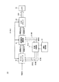
図1は本発明の固定画素型表示システムの第1実施の形態の構成図である。
本発明の固定画素型表示システムの第1実施の形態の固定画素型表示システム(以下、簡略化して、表示システムという)10は、スキャンコンバータ12、映像信号調整部14、制御処理部16、操作指示部18、液晶表示用ドライバ装置(LCDドライバ装置)20、および、液晶表示(LCD)装置22を有する。
【0016】
本発明の第1実施の形態の表示システム10においては、本発明の固定画素型表示装置(またはドットマトリクス方式の表示装置)として、LCD装置22とそのドライバ装置(LCDドライバ装置)20とを用いる場合について例示する。LCDドライバ装置20およびLCD装置22は、本発明の固定画素型表示装置に該当する。
LCD装置22は、CRT表示装置におけるラスタスキャン方式のように、掃引周波数などに応じて画像の表示位置(画素位置)などが変更可能な表示装置ではなく、物理的に固定された二次元状態に配列された複数の画素の位置が構造的に固定している。
【0017】
図2(A)は図1に図解したLCD装置の正面外観図であり、図2(B)は図2(A)の表示部分を示す図である。
図2(A)に図解したように、LCD装置22は、表示領域220とLCD装置操作部222とを有している。LCD装置操作部222は、電源スイッチ、輝度を調整するボタン(スイッチ)などを有する。
図2(B)に図解したように、表示領域220は、中央のセーフ領域SAと、その外周のブランキング領域BAから構成されている。セーフ領域SAは座標(x1,y1)、(x2,y1)、(x1,y2)、(x2,y2)で領域が規定され、ブランキング領域BAは座標(X1,Y1)、(X2,Y1)、(X1,Y2)、(X2,Y2)で領域が規定される。
【0018】
表示システム10の概要を述べる。
LCD装置22などの固定画素の表示装置はコンピュータ等から送られてきた様々なディジタルの映像信号、または、NTSCなどのアナログのTV用映像信号(これらを原映像信号VIDEOという)をスキャンコンバータ12によりLCD装置22のパネルの解像度やサイズ(縦横の比、すなわち、アスペクト比)に合うように変換してLCDドライバ装置20を介してLCD装置22に表示信号S20を供給してLCD装置22に表示させる。
本実施の形態においては、スキャンコンバータ12とLCDドライバ装置20の間に、LCD装置22のパネル(表示領域220)の解像度の映像信号をディジタル信号処理する映像信号調整部14を設けて、エリアセーフマーカーを実現する。
【0019】
映像信号調整部14は、ノーマルスキャン表示(通常表示モード)時に、スキャンコンバータ12で変換された通常変換映像信号VIDEO−1が1ライン毎に発生する水平同期信号H−SYNCの数をカウントし、垂直方向のセーフ領域SAの位置をコントロールする。
また映像信号調整部14は、通常変換映像信号VIDEO−1の1ドットごとに発生するドットクロックD−CLKの数をカウントすることにより水平方向のセーフ領域SAの位置を検出して水平方向の映像信号の処理をコントロールする。その際、映像信号調整部14は、セーフ領域SA外の映像にハーフブランキング(画像を暗くすること) をかけるなどして、表示領域220内のセーフ領域SAをユーザが視覚的に確認できるようにする。
【0020】
その状態でユーザが操作指示部18に設けられたセーフエリアズームボタン、または、LCD装置22のLCD装置操作部222に設けられたセーフエリアズームボタンを押すと、制御処理部16は、映像信号調整部14から制御処理部16に映像信号状態検出信号S14として出力される、そのとき映像信号調整部14がカウントした水平同期信号の値およびドットクロックの値に基づいてスキャンコンバータ12の水平、垂直方向の開始位置、および、水平方向および垂直方向の拡大倍率を計算し、スキャンコンバータ12のレジスタ(メモリ)の設定を変更するため、スキャンコンバータ12に変換制御信号S16を出力する。
【0021】
スキャンコンバータ12は変換制御信号S16で指定された、水平、垂直方向の開始位置、および、水平方向および垂直方向の拡大倍率に基づいて、原映像信号VIDEOの大きさを変換してズーム用映像信号VIDEO−2を出力する。このズーム用映像信号VIDEO−2がLCDドライバ装置20を介してLCD装置22に表示される。
その結果、ユーザが指定した表示領域220のセーフ領域SA部分のみを表示領域220の画面全体に表示することが可能となる。
以下、本発明の実施の形態の詳細を述べる。
【0022】
各種仕様
表示システム10はLCD装置22に各種の映像信号を、映像信号の仕様とLCD装置22の仕様との関係における制約のもとで、ユーザが希望する条件で表示する。
映像信号の仕様とは、たとえば、VESA(Video Electronics Standard Association) に規定された映像信号の仕様をいう。そのような映像信号の仕様としては、解像度について、たとえば、水平画素640x垂直画素480、水平画素720x垂直画素400、水平画素800x垂直画素600、水平画素1024x垂直画素768、水平画素1152x垂直画素864、水平画素1280x垂直画素1024などがある。また、駆動周波数としては、同じ1280x1024画素の解像度の映像信号でも、水平周波数64kHz/垂直周波数60Hz、水平周波数80kHz/垂直周波数75Hz、水平周波数81kHz/垂直周波数77Hz、水平周波数91kHz/垂直周波数85Hzなどがある。
さらに映像信号の仕様としては、たとえば、コンピュータから出力される映像信号などの仕様もある。
【0023】
LCD装置22の仕様とは、たとえば、種々のアスペクト比(画面の縦/横の寸法の比率)、種々の(水平方向の画素数)x(垂直方向の画素数)、駆動周波数などがある。
【0024】
制御処理部
制御処理部16は、操作指示部18、および/またはLCD装置22のLCD装置操作部222を介して指示されるユーザの指示を入力してスキャンコンバータ12の変換処理を制御する。
制御処理部16は、操作指示部18からユーザによって指定される表示モードを示す表示モード指示信号S16Aを生成する。
制御処理部16はまた、映像信号調整部14からの映像信号状態検出信号S14を入力して、スキャンコンバータ12の水平、垂直方向の開始位置、および、水平方向および垂直方向の拡大倍率を計算し、計算した結果を示す、スキャンコンバータ12を制御するための変換制御信号S16B,S16Cを生成する。
制御処理部16はさらに、ユーザが操作する操作指示部18のセーフエリアズームボタンまたはLCD装置操作部222のセーフエリアズームボタンまたはマウスによって指定されたセーフエリアズーム範囲を示す第1マーカー信号MKR1を生成し、このマーカー信号MKR1で指定されるセーフ領域SAを示す情報を変換信号S16Cに含ませてスキャンコンバータ12に出力する。
制御処理部16はまた、操作指示部18から指示されるユーザからの指示に基づいて、図7を参照して述べる処理をスキャンコンバータ12および映像信号調整部14と協働して表示システム10全体の制御処理を行なう。
制御処理部16は本発明の制御手段に該当する。
操作指示部18および/またはLCD装置操作部222のセーフエリアズームボタン、マウスなどは、本発明の操作手段に該当する。
【0025】
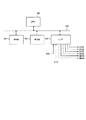
制御処理部16の構成を図3に示す。
制御処理部16は、バス164を介して接続された、マイクロコントローラなどの演算処理部(CPU)160、ランダムアクセスメモリ(RAM)161、リードオンリーメモリ(ROM)162、入出力インタフェース(I/O−IF)163を有する。
ROM162にはCPU160において行なわれる各種プログラムが記憶されており、CPU160はそのようなプログラムの処理に従って、操作指示部18、および/またはLCD装置22のLCD装置操作部222の指定に応じて図7を参照して述べる各種動作制御、および、下記に述べる各種制御信号の生成処理を行なう。
【0026】
制御処理部16で生成する信号の意味を下記に述べる。
(1)表示モード指示信号S16A
表示モード指示信号S16Aは、操作指示部18を介してユーザが指示した、通常表示か部分拡大表示かの表示モードを示す、制御処理部16からスキャンコンバータ12に指示する表示モードを示す信号であり、表示モード指示信号S16B=「0」は通常表示モードを示し、表示モード指示信号S16B=「1」は部分拡大(ズーム)表示モードを示す。
(2)通常表示時の変換信号S16B
通常表示時の変換信号S16Bは、制御処理部16が、映像信号調整部14からの映像信号状態検出信号S14を入力して、通常表示モードにおける、スキャンコンバータ12の水平、垂直方向の開始位置、および、水平方向および垂直方向の拡大倍率を計算し、原映像信号VIDEOを通常変換映像信号VIDEO−1に変換するためのスキャンコンバータ12の変換周波数(変換速度)を示す信号である。
通常表示モードにおけるスキャンコンバータ12における変換周波数は、原映像信号VIDEOと、LCDドライバ装置20およびLCD装置22の仕様が決まれば決まるが、本実施の形態においては、各種の原映像信号VIDEO、各種のLCDドライバ装置20およびLCD装置22を選択して使用可能なことを想定しているので、制御処理部16から通常表示時の変換信号S16Bをスキャンコンバータ12に設定するようにしている。換言すれば、仕様の決まったLCDドライバ装置20およびLCD装置22を動作させる場合には、通常表示時の変換信号S16Bをスキャンコンバータ12に設定しておくことができる。
(3)ズーム表示時の変換信号S16C
ズーム表示時の変換信号S16Cは、制御処理部16が、映像信号調整部14からの映像信号状態検出信号S14を入力して、ズーム表示モードのときに、スキャンコンバータ12の水平、垂直方向の開始位置、および、水平方向および垂直方向の拡大倍率を計算し、スキャンコンバータ12において原映像信号VIDEOを変換するときの変換速度(または変換周波数)を示す信号である。ズーム表示時の変換信号S16Cはズームの率に応じて変化する。このズーム表示時の変換信号S16Cは、第1マーカー信号MKR1によって指定されるセーフ領域SAの範囲も示す。
ユーザは操作指示部18を介して直観的、または、視覚的にズームの倍率を指定することが多いから、制御処理部16はユーザが指定したそのようなズームの倍率に応じて変換周波数を換算して、ズーム表示時の変換信号S16Cとしてスキャンコンバータ12に出力する。
(4)表示モード指示信号S16D
表示モード指示信号S16Dは実質的に表示モード指示信号S16Aと同じである。表示モード指示信号S16Aが制御処理部16からスキャンコンバータ12に出力されるのに対して、表示モード指示信号S16Dは制御処理部16から映像信号調整部14に出力される。
(5)第1マーカー信号MKR1
第1マーカー信号MKR1は、操作指示部18のセーフエリアズームボタン、または、LCD装置操作部222のセーフエリアズームボタンを介してユーザが指示したLCDドライバ装置20の表示領域220内のセーフ領域SAの範囲を示す信号である。
(6)第2マーカー信号MKR2
第2マーカー信号MKR2は実質的に第1マーカー信号MKR1と同じである。第2マーカー信号MKR2は制御処理部16から映像信号調整部14に出力される。
【0027】
上述した各種信号は、I/O−IF163を介して、スキャンコンバータ12、映像信号調整部14に接続されている。また、操作指示部18ともI/O−IF163を介して信号の授受が行なわれる。
【0028】
スキャンコンバータ
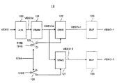
図4は図1に図解したスキャンコンバータ12の構成例を示す図である。
スキャンコンバータ12は、アナログ形式の原映像信号VIDEOについて制御処理部16から入力される、表示モード指示信号S16A、通常表示時の変換信号S16B、ズーム表示時の変換処理を行い、通常変換映像信号VIDEO−1またはズーム用映像信号VIDEO−2を生成する。
スキャンコンバータ12は、本発明の映像信号変換手段に該当する。
【0029】
通常変換映像信号VIDEO−1は、通常表示モードにおいてアナログ形式の原映像信号VIDEOをLCD装置22に表示するためのディジタル形式の映像信号に変換した信号である。
ズーム用映像信号VIDEO−2は、ズーム表示モードにおいて原映像信号VIDEOの一部をズーム拡大してLCD装置22に表示するためのディジタル形式の映像信号に変換した信号である。
【0030】
スキャンコンバータ12は、A/D変換部120と、ビデオ信号メモリ(VRAM)121と、第1の変換処理部122と、バッファメモリ(BUF)123と、スイッチ125と、第2の変換処理部127と、バッファメモリ(BUF)128とを有する。
本実施の形態においては、原映像信号VIDEOとしてアナログ形式の映像信号が入力される場合を想定している。なお、原映像信号VIDEOがディジタル形式の映像信号の場合は、A/D変換部120は不要である。
【0031】
A/D変換部120は、連続的に入力されるアナログ形式の原映像信号VIDEOを、その原映像信号VIDEOの周波数で規定されるサンプリング周波数のクロック信号D−CLKに応じてサンプリングして、ディジタル形式の映像信号VIDEOdに変換して、ビデオ信号メモリ(VRAM)121に出力する。
ビデオ信号メモリ(VRAM)121は、A/D変換部120でディジタル形式の変換した映像信号VIDEOdを、1フィールド形式で記憶し、2フィールド分の映像信号VIDEOdを記憶したとき、最終的に、LCD装置22に表示される形態の1フレーム分の原映像信号VIDEOdを2次元状に記憶する。
【0032】
第1の変換処理部122は、ビデオ信号メモリ(VRAM)121に記憶された1フレーム分の映像信号VIDEOdを、(通常表示モード時(S16A=0))制御処理部16から出力される通常表示時の変換信号S16Bに応じて、LCDドライバ装置20およびLCD装置22の仕様に応じた、通常変換映像信号VIDEO−1に変換する。
通常変換映像信号VIDEO−1は、通常表示モードにおいてアナログ形式の原映像信号VIDEOをLCD装置22に、拡大も縮小もなしに、かつ、削除も追加もなしに、実質的に同じ内容で表示するためのディジタル形式の映像信号に変換した信号である。
第1の変換処理部122において変換された1フレーム分の第1変換映像信号がバッファメモリ(BUF)123に記憶される。
【0033】
スイッチ125は、制御処理部16から出力される表示モード指示信号S16Aが「0」の時、実線で示した状態で、通常表示時の変換信号S16Bを第1の変換処理部122に出力する。他方、表示モード指示信号S16Aが「1」のとき、すなわち、操作指示部18またはLCD装置操作部222におけるセーフエリアズームボタン(以下、操作指示部18にセーフエリアズームボタンがある場合についてのみ述べる)が押されたズーム表示モードのとき、破線で示した位置に駆動されて、ズーム表示時の変換信号S16Cを第2の変換処理部127に出力する。表示モード指示信号S16Aは上述したように、「0」の場合は通常表示モードを示し、「1」の場合はズーム表示モード(または部分拡大表示モード)を示す。
【0034】
第2の変換処理部127は、ビデオ信号メモリ(VRAM)121から出力される映像信号VIDEO(a)を、制御処理部16から出力されるズーム表示時の変換信号S16Cに応じたセーフ領域SAについて指定された拡大率で変換処理して、ズーム用映像信号VIDEO−2を生成する。
バッファメモリ(BUF)128は、第2の変換処理部127で処理されたズーム用映像信号VIDEO−2を記憶する。
【0035】
なお、スキャンコンバータ12において、バッファメモリ(BUF)123およびバッファメモリ(BUF)128は必須ではなく、第1の変換処理部122からの通常変換映像信号VIDEO−1、第2の変換処理部127からの部分拡大映像信号VIDEO−2を直接、後段の映像信号調整部14に出力することもできる。
【0036】
また、スイッチ125を削除し、制御処理部16から、変換信号S16BかS16Cのいずれかを出力してもよい。
【0037】
映像信号調整部
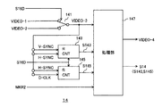
図5は図1に図解した映像信号調整部14の構成例を示す図である。
映像信号調整部14は、ノーマルスキャン表示(通常表示モード)時に、スキャンコンバータ12で変換された通常変換映像信号VIDEO−1が1ライン毎に発生する水平同期信号H−SYNCの数をカウントし、垂直方向のセーフ領域SAの位置をコントロールする。また映像信号調整部14は、1画素を示す1ドットごとに発生するドットクロックD−CLKの数をカウントすることにより水平方向のセーフ領域SAの位置を検出して水平方向の映像信号の処理をコントロールする。その際、セーフ領域SA外の映像にハーフブランキング(画像を暗くすること) をかけるなどして、表示領域220内のセーフ領域SAをユーザが視覚的に確認できるようにする。
また、映像信号調整部14は、カウントした水平同期信号の値およびドットクロックの値を示す映像信号状態検出信号S14を制御処理部16に出力する。
映像信号調整部14は本発明の映像信号調整手段に該当する。
【0038】
映像信号調整部14の詳細は図5および図6(A)〜(C)を参照して後述する。
映像信号調整部14は、スイッチ141と、水平同期信号カウンタ143と、ドットクロックカウンタ145と、映像信号処理部147とを有する。
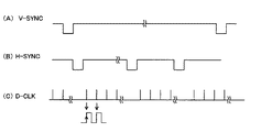
図6(A)〜(C)は映像信号調整部14の動作を説明するタイミングチャートである。図6(A)〜(C)を参照して映像信号調整部14の動作の概要を述べる。
【0039】
スイッチ141は制御処理部16から出力される表示モード指示信号S16Dに応じて、通常変換映像信号VIDEO−1またはズーム用映像信号VIDEO−2のいずれかを選択出力する。制御処理部16から出力される表示モード指示信号S16Dは、「0」の場合は通常表示モードを示し、「1」の場合はズーム表示モードを示す。したがって、スイッチ141は「0」の表示モード指示信号S16Dのとき通常変換映像信号VIDEO−1を選択出力し、「1」の表示モード指示信号S16Dのときズーム用映像信号VIDEO−2を選択出力する。通常表示モードにおいてスイッチ141で選択出力された信号をセーフエリアマーカー(SAM)付拡大映像信号VIDEO−3と呼ぶ。
映像信号VIDEO−3は映像信号処理部147、水平同期信号カウンタ143、ドットクロックカウンタ145に入力される。
【0040】
水平同期信号カウンタ143は、表示モード指示信号S16Dに応じて、映像信号VIDEO−3に含まれる垂直同期信号V−SYNCをリセットパルスとして、垂直同期信号V−SYNCが到来するたび、すなわち、毎フィールドごと(または毎フレームごと)、映像信号VIDEO−3に含まれる水平同期信号H−SYNCの数を計数する。その結果、水平同期信号カウンタ143は1フィールド(または1フレーム)ごとの映像信号VIDEO−3の水平方向の位置を検出することができ検出した水平方向位置データS143を映像信号処理部147に出力する。
ドットクロックカウンタ145は、表示モード指示信号S16D=「0」のとき、映像信号VIDEO−3に含まれる水平同期信号H−SYNCをリセットパルスとして、映像信号VIDEO−3に含まれるドットクロック信号D−CLKの数を計数する。ドットクロックカウンタ145は、1ドットクロックを拡大して図解したように、ドットクロックD−CLKの立上りの変化を計数する。したがって、ドットクロックカウンタ145は映像信号VIDEO−3の各水平方向の映像データの位置を検出することができ、検出した水平方向位置データS145を映像信号処理部147に出力する。なお、図6(C)には、図解の簡略化のため、ドットクロックD−CLKを1本の線で示したが、実際のドットクロックD−CLKは、部分的に拡大表示したように、ハイレベル/ローレベルが等間隔である。
【0041】
映像信号処理部147は、水平方向位置データS143および水平方向位置データS145を映像信号状態検出信号S14として制御処理部16に出力する。したがって、制御処理部16は映像信号VIDEO−3の水平位置および垂直位置を知ることができる。
【0042】
映像信号処理部147はまた、水平方向位置データS143および水平方向位置データS145を入力して映像信号VIDEO−3の水平および水平方向の位置と、セーフエリアマーカー(SAM)付拡大映像信号VIDEO−3に付加された(重畳された)セーフ領域SAを示すマーカー、または、第2マーカー信号MKR2で指定されたセーフ領域SAを判断して、セーフ領域SAの外部について、たとえば、ハーフブランキング(画像を暗くすること) など処理を行なう。
映像信号処理部147で処理したハーフブランキング処理などが行なわれた映像信号を調整後映像信号VIDEO−4という。
【0043】
LCD装置22は調整後映像信号VIDEO−4を入力して表示信号S20としてLCD装置22に出力する。その結果、ズーム表示モードにおいては、LCD装置22にユーザが操作指示部18のセーフエリアズームボタンで指定した映像が表示される。
なお、通常表示モードにおいては、スキャンコンバータ12からの通常変換映像信号VIDEO−1がLCD装置22に表示される。
【0044】
LCDドライバ装置20は、映像信号調整部14の映像信号処理部147から出力された映像信号VIDEO−3、または、調整後映像信号VIDEO−4を表示信号S20としてLCD装置22に表示処理する動作を行なう。
【0045】
図7の図解したフローチャートを参照して表示システム10、特に、制御処理部16の演算処理部(CPU)160の処理を述べる。
【0046】
ステップ1(S1):仕様設定操作
ステップ1において、上述した映像信号の各種仕様およびLCD装置22の仕様は、表示システム10の動作を開始する前段階(初期段階)において、たとえば、ユーザによって操作指示部18を用いて制御処理部16に事前に設定される。
制御処理部16は操作指示部18を介して設定された各種仕様を入力して、制御処理部16内のメモリ、たとえば、ランダムアクセスメモリ(RAM)161(図3)に記憶する。すなわち、表示システム10の動作の前段階において、1または複数の表示対象の映像信号の仕様と、LCD装置22の仕様とを制御処理部16のメモリに記憶しておく。
たとえば、スキャンコンバータ12に入力され得る各種の映像信号の1つを入力してLCD装置22に表示するとき、ユーザが操作指示部18から映像信号(原映像信号VIDEO)の種類を指定する。制御処理部16が指定された情報を入力して制御処理部16内のメモリ(RAM161)に記憶し、制御処理部16がメモリに記憶した指定された映像信号の仕様、周波数、ドット数などをスキャンコンバータ12に設定する。なお、制御処理部16を介して、あるいは、直接、スキャンコンバータ12にLCD装置22のアスペクト比、(水平方向の画素数)x(垂直方向の画素数)などの仕様を設定してもよい。その場合、上述した制御処理部16からスキャンコンバータ12へのLCD装置22の仕様の出力は不要となる。
設定ステップ1における仕様設定処理により、ユーザは、自分の望みの映像信号を、LCD装置22の仕様に合わせて、図2(B)に例示した、LCD装置22の表示領域に表示することが可能となる。
【0047】
ステップ2(S2):表示領域設定操作
ステップ2において、ユーザは、図2(A)に例示したLCD装置22の表示可能領域のうち、初期設定として、図8(A)に図解したように、セーフ領域SAとして使用する領域およびブランキング領域BAとして使用する領域を、操作指示部18を用いて制御処理部16に設定する。
制御処理部16は設定された領域データをメモリ、たとえば、RAM161に記憶する。
ユーザが設定する領域データとしては、図2(B)に例示したように、LCD装置22の表示画面の画素の座標位置、すなわち、原点位置(0,0)に対するx1,x2,y1,y2である。制御処理部16は、4隅の座標位置(x1,y1),(x2,y1),(x1,y2),(x2,y2)をメモリ(RAM161)に記憶する。
【0048】
動作1(OP1):通常表示
これにより、原映像信号VIDEOが入力されると、スキャンコンバータ12は、初期状態において、制御処理部16から表示モード指示信号S16A=「0」が出力されている通常変換モードにおいて、指定された原映像信号VIDEOの周波数に対応したサンプリング周波数でディジタルの通常変換映像信号VIDEO−1に変換する。すなわち、スキャンコンバータ12は、通常変換モードにおいて、原映像信号VIDEOを、LCD装置22のアスペクト比、解像度または(水平方向の画素数)x(垂直方向の画素数)に応じて、通常変換映像信号VIDEO−1に変換する。
通常変換映像信号VIDEO−1がLCD装置22のセーフ領域SAに表示される。
なお、通常変換映像信号VIDEO−1と呼ぶのは、ズーム用映像信号VIDEO−2との区別のためである。
【0049】
映像信号調整部14は、通常表示モードにおいて、上述したように、通常変換映像信号VIDEO−1の1ライン毎に発生する同期信号、すなわち、水平同期信号H−SYNCをカウントしLCD装置22の画面の垂直方向のセーフエリアをコントロールする。また、1ドット(1画素)ごとに発生するクロックであるドットクロックD−CLKをカウントすることによりLCD装置22の画面の水平方向のセーフエリアをコントロールする。
【0050】
ステップ3(S3):セーフエリア確認表示
動作2(OP2):セーフ領域表示
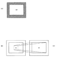
ステップ2における領域設定があったときで、ユーザからセーフ領域SAの確認要求指示があると、制御処理部16は、操作指示部18を介したユーザの指定があった場合、映像信号調整部14に指令して、映像信号処理部147においてセーフ領域SAの外部の部分を、たとえば、図8(A)に斜線で示したように、ハーフブランキング状態に表示させる。これにより、セーフ領域SAが視覚的に容易に確認できる。
ただし、ユーザからセーフ領域SAの確認表示指定がない場合はそのような表示処理は行なわない。
【0051】
ステップ2におけるセーフ領域SA設定処理により、ユーザはセーフ領域SAの領域を指定でき、さらに希望すれはユーザは自己が設定したセーフ領域SAを目視により確認することができる。
【0052】
ステップ1の仕様設定操作は、使用するLCD装置22と表示対象の映像信号が定まると1回行なうだけであるが、ステップ2、3の処理は必要に応じて何度でも行なうことができる。すなわち、セーフ領域SAの領域はユーザの希望に応じて変更できる。
【0053】
ステップ3(S3):表示領域変更指定
セーフ領域SAの変更方法としては、たとえば、図8(B)に例示するように、ユーザが、操作指示部18のセーフエリアズームボタン、あるいは、マウスを用いて、LCD装置22の表示領域220におけるセーフ領域SAの境界線を区画する。これにより、ズーム表示領域が指定される。
【0054】
動作3(OP3):表示領域変更処理
通常表示モードにおいて通常変換映像信号VIDEO−1をLCD装置22に表示しているとき、ユーザが操作指示部18内のセーフエリアズームボタンを押すとまたはマウスを操作すると、制御処理部16はそのボタン操作が入力されたときの制御処理部16から出力される映像信号状態検出信号S14を入力して、映像信号調整部14がカウントした垂直方向位置および水平方向位置の値に基づいてスキャンコンバータ12のの水平方向および垂直方向の開始位置、及び、水平方向および垂直方向の拡大倍率を計算し、スキャンコンバータ12の変換条件を変更する。
スキャンコンバータ12はズーム時の変換制御信号S16Cで指定された変換条件に従って、セーフエリアズームボタンまたはマウスで指定された周囲の映像信号を、図8(C)に図解したように、拡大表示するための変換処理を行なう。
【0055】
さらにユーザは、操作指示部18に設けたズーム指定スイッチ、または、LCD装置操作部222に設けたズーム指定スイッチをズームしただけ押す。制御処理部16はズーム指定スイッチの操作時間の間、所定の比率でセーフエリアズームボタンで指定された領域の映像信号を拡大表示させるための倍率を計算した変換制御信号S16Cとしてスキャンコンバータ12に出力する。スキャンコンバータ12は指定された変換条件で原映像信号VIDEOを変換する。
これにより、ユーザがズーム指定スイッチを操作している間、映像信号が拡大表示される。なお、映像信号の拡大表示倍率は最大値を指定しておき、最大倍率に到達したら、制御処理部16はズーム指定スイッチの操作を無効化する。
【0056】
あるいは、制御処理部16は、好ましくは、セーフエリアズームボタンの指定があったとき、セーフエリアズームボタンで指定された所定範囲の映像信号をセーフ領域SAの範囲内、または、表示領域220の全体にわたって表示されるように、スキャンコンバータ12に変換制御信号S16Cを出力することができる。すなわち、制御処理部16は、表示領域220の全体画面の大きさ、または、セーフ領域SAの大きさが判り、さらに、セーフエリアズームボタンで指定された範囲が分かるから、計算により、スキャンコンバータ12に指定する拡大率を求める事が出来る。
このような処理によれば、ユーザがセーフエリアズームボタンによって指定した範囲の映像信号が、セーフエリアズームボタンを操作するだけで、セーフ領域SA全体、または、表示領域220全体にわたって表示される。
【0057】
ステップ4(S4):表示モード復帰指定
セーフ領域SAを変更した後、通常表示モードに復帰するには、ユーザは操作指示部18に設けられた「通常表示モード指定スイッチ」を押す。
【0058】
動作4(OP4):表示モード復帰処理
制御処理部16は、「通常表示モード指定スイッチ」が押されたことを検出したら、RAM161に記憶してある通常表示モードのスキャンコンバータ12の動作条件を変換制御信号S16としてスキャンコンバータ12に出力する。
それにより、スキャンコンバータ12は通常表示モードの変換処理を行なう。その結果、通スキャンコンバータ12から通常変換映像信号VIDEO−1が出力されて、LCD装置22に表示される。
【0059】
第2実施の形態
第1実施の形態は、LCD装置22の表示領域220に表示されている映像信号をセーフエリアズームボタンまたはマウスで指定した範囲をズーム表示(拡大表示)させ、一度に通常表示モードに戻す場合について述べたが、第1実施の形態においてズーム表示モードで拡大表示されている映像を、通常変換映像信号VIDEO−1まで、任意の尺度で連続的に縮小表示させることもできる。
その場合は、たとえば、操作指示部18に縮小表示を指定するジョイステックを設けるか、LCD装置操作部222に縮小表示指示ボタンを設け、ジョイステックまたは縮小表示指示ボタンが押されている間、制御処理部16で縮小指示信号を読み取り、その時の縮小倍率を計算して、ズーム時の変換制御信号S16Cとしてスキャンコンバータ12に出力する。
スキャンコンバータ12は指定された倍率の変換条件で原映像信号VIDEOを変換する。
【0060】
本発明の実施に際しては上述した実施の形態に限定されない。
たとえば、図1を参照して例示した各部分の処理機能、および、機能分担は、例示にすぎず、表示システム10として上述した処理が遂行できればよい。
【0061】
【発明の効果】
本発明によれば、映像信号の拡大または縮小の範囲を任意にかつ容易に指定することができる。
また本発明によれば、拡大される範囲を事前に視覚的に確認することができる。
さらに本発明によれば、映像信号を希望するだけ、拡大または縮小表示することができる。
【図面の簡単な説明】
【図1】図1は本発明の固定画素型表示システムの第1実施の形態の表示システムの構成図である。
【図2】図2(A)は図1に図解したLCD装置の正面外観図であり、図2(B)は図2(A)の表示部分を示す図である。
【図3】図3は図1に図解した制御処理部の構成例を示す図である。
【図4】図4は図1に図解したスキャンコンバータの構成例を示す図である。
【図5】図5は図1に図解した映像信号調整部の構成例を示す図である。
【図6】図6(A)〜(C)は、図5に図解した映像信号調整部における動作を説明するための信号波形図である。
【図7】図7は図1に図解した固定画素型表示システムの動作を示すフローチャートである。
【図8】図8(A)〜(C)は、図7を参照して述べる表示システムの動作に伴うLCD装置に表示される表示状態を示す図である。
【符号の説明】
10・・表示システム
12・・スキャンコンバータ
120・・A/D変換部、121・・ビデオ信号メモリ
122・・第1の変換処理部、123・・バッファメモリ
125・・スイッチ
127・・第2の変換処理部、128・・バッファメモリ
14・・映像信号調整部
141・・スイッチ、143・・水平同期信号カウンタ
145・・ドットクロックカウンタ
147・・映像信号処理部
16・・制御処理部
160・・演算処理部(CPU)、161・・RAM
162・・ROM、163・・I/O−IF
164・・バス
18・・操作指示部
20・・LCDドライバ装置
22・・LCD装置
220・・表示領域(SA・・セーフ領域BA・・ブランキング領域)
222・・LCD装置操作部
VIDEO・・原映像信号、VIDEO−1・・通常変換映像信号
VIDEO−2・・ズーム用映像信号
VIDEO−3・・セーフエリアマーカー付拡大映像信号
VIDEO−4・・調整後映像信号
S14・・映像信号状態検出信号
S16A、S16D・・表示モード指示信号
S16B・・通常表示時の変換信号、S16C・・ズーム表示時の変換信号
MKR1、MKR2・・マーカー信号、S20・・表示信号[0001]
TECHNICAL FIELD OF THE INVENTION
The present invention performs a fixed pixel type display system for displaying an image on a fixed pixel type display device (or a dot matrix type display device) having a fixed pixel position, such as a liquid crystal display device, and performs processing therefor. The present invention relates to a display processing device.
In particular, the present invention relates to a technique for displaying a video signal in such a fixed pixel type display device at a desired position in a desired size in a simple manner.
[0002]
[Prior art]
When various kinds of video (image) signals are selectively switched and displayed on an image display device such as a CRT display device or a liquid crystal display device, the display device is adjusted so as to match the resolution and aspect ratio (aspect ratio) of the image display device. Is converted and displayed.
Japanese Patent Application Laid-Open No. 2000-305555 discloses a technique for judging the specification of a video signal and performing a predetermined conversion so as to conform to the specification of a liquid crystal display device, and displaying the video signal even when the format of the video signal is unknown. Has been disclosed.
[0003]
The image display device is provided with a region where a video signal (image) is displayed and a region (overscan region) located on the outer periphery and where no image is normally displayed. Therefore, an image cannot be displayed in the overscan area.
[0004]
When an image captured by a digital still camera is displayed on a display device of a raster scan system, for example, a CRT display device, the captured image is also located in the overscan region, and a part of the image located in the overscan region is not displayed. . To solve such a problem, Japanese Patent Laying-Open No. 2000-81867 discloses a technique in which an image display range is changed by an output range changing unit to display an image in an overscan area.
[0005]
When a part of a screen (image) is enlarged and displayed on a fixed pixel type display device (dot matrix type display device) such as a liquid crystal display device, a raster scan method such as a raster scan method such as a CRT display device has heretofore been used. Since enlargement display cannot be performed by changing the condition, for example, changing the sweep frequency, a fixed enlargement range (or magnification) is prepared in advance, and one of a plurality of fixed enlargement ranges is selected.
[0006]
[Patent Document 1]
JP 2000-305555 A
[Patent Document 2]
JP 2000-81867 A
[0007]
[Problems to be solved by the invention]
However, when a part of the screen is enlarged and displayed on a liquid crystal display device or the like, the above-described method is limited to a fixed enlargement range and encounters the inconvenience that the user cannot freely set the enlargement range and magnification. ing.
Furthermore, the conventional method cannot visually confirm the actual enlargement range selected by the user, and it is necessary to repeat the selection several times by trial and error, which takes time, effort, and low operability. Have encountered.
[0008]
The broadcast monitor device also has a function called a "safe area marker" that indicates a place (safe area) that is guaranteed to be displayed on a home television receiver at the time of underscan. However, in the conventional device, the safe area is different from the display area of the monitor during actual overscan.
[0009]
Therefore, it is desired to specify an arbitrary range on the screen of the display device and enlarge that portion to the entire screen by pressing a button, selecting a menu, or the like.
[0010]
An object of the present invention is to provide a display processing device and a fixed pixel type display which enable an image displayed on a fixed pixel type display device (or a dot matrix type display device) to be easily displayed at an arbitrary position and at an arbitrary magnification. It is to provide a system.
[0011]
Another object of the present invention is to provide a display processing device and a fixed pixel type display system that allow a user to visually recognize (view) a state set by the user during such display processing.
[0012]
[Means for Solving the Problems]
According to a first aspect of the present invention, a first conversion means for converting a first video signal into a digital second video signal according to the resolution and aspect ratio of a fixed pixel type display device, A second conversion means for converting a video signal in a specified range among the second video signals displayed on the type display device under specified conversion conditions; and the second display means displayed on the fixed pixel type display device. Video signal position detection means for detecting a horizontal position and a vertical position of a second video signal; and a video signal when a safe area zoom range is designated for a video signal displayed on the fixed pixel type display device. The video signal in the safe area zoom range centered on the horizontal position and the vertical position of the second video signal detected by the position detection means is enlarged to the display area of the fixed pixel type display device. To convert the viewable video signal, display processing apparatus and a control means for specifying a conversion condition of the second conversion means.
[0013]
According to a second aspect of the present invention, a fixed pixel type display device, an operation instructing unit for instructing display contents, and a first video signal in a digital format corresponding to the resolution and aspect ratio of the fixed pixel type display device A first conversion means for converting the image signal into a second video signal, and a video signal in a range designated through the operation instruction means among the second video signals displayed on the fixed pixel type display device. Second conversion means for converting under specified conversion conditions, video signal position detection means for detecting a horizontal position and a vertical position of the second video signal displayed on the fixed pixel type display device, When a safe area zoom range is designated for the video signal displayed on the fixed pixel type display device via the operation instruction means, the horizontal position of the second video signal detected by the video signal position detection means is determined. In order to convert the video signal in the safe area zoom range centered on the horizontal position and the vertical position into a video signal that can be enlarged and displayed in the display area of the fixed pixel display device, the conversion condition of the second conversion unit is set as follows. A fixed pixel type display system having a control means for designating is provided.
[0014]
The first conversion means converts the first video signal into a digital second video signal according to the resolution and the aspect ratio of the fixed pixel type display device.
The second conversion means converts a video signal in a specified range among the second video signals displayed on the fixed pixel display device under a specified conversion condition.
The video signal position detecting means detects a horizontal position and a vertical position of the second video signal displayed on the fixed pixel display device.
When a safe area zoom range is specified for a video signal displayed on the fixed pixel display device, the control unit controls the horizontal position and the vertical direction of the second video signal detected by the video signal position detection unit. In order to convert a video signal in the safe area zoom range centered on a position into a video signal that can be enlarged and displayed in a display area of the fixed pixel display device, a conversion condition of the second conversion unit is specified.
Second conversion means converts the video signal under the specified conversion condition. The result is displayed on the fixed pixel type display device.
[0015]
BEST MODE FOR CARRYING OUT THE INVENTION
First embodiment
FIG. 1 is a configuration diagram of a first embodiment of a fixed pixel type display system of the present invention.
A fixed pixel type display system (hereinafter, simply referred to as a display system) 10 according to a first embodiment of the fixed pixel type display system of the present invention includes a
[0016]
In the
The
[0017]
FIG. 2A is a front external view of the LCD device illustrated in FIG. 1, and FIG. 2B is a diagram illustrating a display portion of FIG. 2A.
As illustrated in FIG. 2A, the
As illustrated in FIG. 2B, the
[0018]
An outline of the
A fixed pixel display device such as the
In the present embodiment, a video
[0019]
The video
The video
[0020]
In this state, when the user presses the safe area zoom button provided on the
[0021]
The
As a result, only the safe area SA portion of the
Hereinafter, embodiments of the present invention will be described in detail.
[0022]
Various specifications
The
The specification of the video signal refers to, for example, the specification of a video signal defined in VESA (Video Electronics Standards Association). The specifications of such a video signal include, for example, a resolution of a horizontal pixel 640 × vertical pixel 480, a horizontal pixel 720 × vertical pixel 400, a horizontal pixel 800 × vertical pixel 600, a horizontal pixel 1024 × vertical pixel 768, a horizontal pixel 1152 × vertical pixel 864, There are 1280 horizontal pixels × 1024 vertical pixels. Further, as the driving frequency, even a video signal having the same resolution of 1280 × 1024 pixels has a horizontal frequency of 64 kHz / vertical frequency of 60 Hz, a horizontal frequency of 80 kHz / vertical frequency of 75 Hz, a horizontal frequency of 81 kHz / vertical frequency of 77 Hz, a horizontal frequency of 91 kHz / vertical frequency of 85 Hz, and the like. is there.
Further, as a specification of a video signal, for example, there is a specification of a video signal output from a computer.
[0023]
The specifications of the
[0024]
Control processing unit
The
The
The
The
The
The
The safe area zoom button, the mouse, and the like of the
[0025]
FIG. 3 shows the configuration of the
The
Various programs performed by the
[0026]
The meaning of the signal generated by the
(1) Display mode instruction signal S16A
The display mode instruction signal S16A is a signal indicating the display mode of the normal display or the partially enlarged display, which is indicated by the user via the
(2) Conversion signal S16B during normal display
The
The conversion frequency in the
(3) Conversion signal S16C for zoom display
When the
Since the user often specifies the zoom magnification intuitively or visually via the
(4) Display mode instruction signal S16D
The display mode instruction signal S16D is substantially the same as the display mode instruction signal S16A. While the display mode instruction signal S16A is output from the
(5) First marker signal MKR1
The first marker signal MKR1 is output to the safe area SA in the
(6) Second marker signal MKR2
The second marker signal MKR2 is substantially the same as the first marker signal MKR1. The second marker signal MKR2 is output from the
[0027]
The various signals described above are connected to the
[0028]
Scan converter
FIG. 4 is a diagram illustrating a configuration example of the
The
The
[0029]
The normal conversion video signal VIDEO-1 is a signal obtained by converting the analog original video signal VIDEO into a digital video signal for display on the
The zoom video signal VIDEO-2 is a signal obtained by converting a part of the original video signal VIDEO into a digital video signal to be displayed on the
[0030]
The
In the present embodiment, it is assumed that an analog video signal is input as the original video signal VIDEO. When the original video signal VIDEO is a digital video signal, the A /
[0031]
The A /
The video signal memory (VRAM) 121 stores the video signal VIDEOd converted in digital format by the A /
[0032]
The first
The normal converted video signal VIDEO-1 displays the analog original video signal VIDEO in the normal display mode on the
The first converted video signal for one frame converted by the first
[0033]
When the display mode instruction signal S16A output from the
[0034]
The second
The buffer memory (BUF) 128 stores the zoom video signal VIDEO-2 processed by the second
[0035]
Note that in the
[0036]
Further, the
[0037]
Video signal adjustment unit
FIG. 5 is a diagram illustrating a configuration example of the video
The video
Further, the video
The video
[0038]
The details of the video
The video
6A to 6C are timing charts for explaining the operation of the video
[0039]
The
The video signal VIDEO-3 is input to the video
[0040]
The horizontal
When the display mode instruction signal S16D = "0", the dot clock counter 145 uses the horizontal synchronizing signal H-SYNC included in the video signal VIDEO-3 as a reset pulse, and sets the dot clock signal D- included in the video signal VIDEO-3 as a reset pulse. Count the number of CLKs. The dot clock counter 145 counts the rising change of the dot clock D-CLK as illustrated by enlarging the one dot clock. Therefore, the
[0041]
The video
[0042]
The video
The video signal that has been subjected to the half-blanking process or the like processed by the video
[0043]
The
In the normal display mode, the normal conversion video signal VIDEO-1 from the
[0044]
The
[0045]
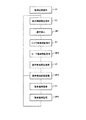
With reference to the illustrated flowchart of FIG. 7, the processing of the
[0046]
Step 1 (S1): Specification setting operation
In
The
For example, when one of various video signals that can be input to the
By the specification setting process in the setting
[0047]
Step 2 (S2): Display area setting operation
In
The
As illustrated in FIG. 2B, the area data set by the user includes the coordinate position of the pixel on the display screen of the
[0048]
Operation 1 (OP1): Normal display
As a result, when the original video signal VIDEO is input, the
Normally converted video signal VIDEO-1 is displayed in safe area SA of
It should be noted that the normal conversion video signal VIDEO-1 is used to distinguish it from the zoom video signal VIDEO-2.
[0049]
In the normal display mode, the video
[0050]
Step 3 (S3): Safe area confirmation display
Operation 2 (OP2): Safe area display
When the area setting in
However, if there is no confirmation display designation of the safe area SA from the user, such display processing is not performed.
[0051]
By the safe area SA setting processing in
[0052]
The specification setting operation in
[0053]
Step 3 (S3): Display area change designation
As a method of changing the safe area SA, for example, as illustrated in FIG. 8B, the user uses the safe area zoom button of the
[0054]
Operation 3 (OP3): Display area change processing
When the user presses the safe area zoom button in the
The
[0055]
Further, the user presses the zoom designation switch provided on the
As a result, the video signal is enlarged and displayed while the user operates the zoom designation switch. Note that a maximum value is designated as the enlargement display magnification of the video signal, and when reaching the maximum magnification, the
[0056]
Alternatively, preferably, when the safe area zoom button is specified, the
According to such processing, a video signal in a range specified by the user with the safe area zoom button is displayed over the entire safe area SA or the
[0057]
Step 4 (S4): Display mode return designation
After changing the safe area SA, to return to the normal display mode, the user presses a “normal display mode designation switch” provided on the
[0058]
Operation 4 (OP4): Display mode return processing
When detecting that the “normal display mode designating switch” is pressed, the
Thereby, scan
[0059]
Second embodiment
The first embodiment relates to a case where a video signal displayed on the
In this case, for example, a joystick for designating reduced display is provided in the
The
[0060]
The embodiment of the present invention is not limited to the above embodiment.
For example, the processing functions and the function sharing of each part illustrated with reference to FIG. 1 are merely examples, and it is sufficient that the processing described above as the
[0061]
【The invention's effect】
According to the present invention, the range of enlargement or reduction of a video signal can be arbitrarily and easily specified.
Further, according to the present invention, the range to be enlarged can be visually confirmed in advance.
Further, according to the present invention, the video signal can be enlarged or reduced as much as desired.
[Brief description of the drawings]
FIG. 1 is a configuration diagram of a display system according to a first embodiment of a fixed pixel type display system of the present invention.
2 (A) is a front external view of the LCD device illustrated in FIG. 1, and FIG. 2 (B) is a diagram showing a display portion of FIG. 2 (A).
FIG. 3 is a diagram illustrating a configuration example of a control processing unit illustrated in FIG. 1;
FIG. 4 is a diagram illustrating a configuration example of the scan converter illustrated in FIG. 1;
FIG. 5 is a diagram illustrating a configuration example of a video signal adjustment unit illustrated in FIG. 1;
6 (A) to 6 (C) are signal waveform diagrams for explaining an operation in the video signal adjusting unit illustrated in FIG. 5;
FIG. 7 is a flowchart showing an operation of the fixed pixel type display system illustrated in FIG. 1;
FIGS. 8A to 8C are diagrams showing a display state displayed on the LCD device in association with the operation of the display system described with reference to FIG.
[Explanation of symbols]
10. Display system
12. Scan converter
120 A / D converter, 121 video signal memory
122 first
125 switch
127 second conversion processing unit, 128 buffer memory
14. Image signal adjustment unit
141 switch, 143 horizontal sync signal counter
145 dot clock counter
147 ... Video signal processing unit
16 Control processing unit
160 arithmetic processing unit (CPU), 161 RAM
162 ROM, 163 I / O-IF
164 bus
18. Operation instruction section
20 LCD driver device
22 LCD device
220 display area (SA safe area BA blanking area)
222 LCD operation unit
VIDEO: Original video signal, VIDEO-1: Normally converted video signal
VIDEO-2: Video signal for zoom
VIDEO-3: Enlarged video signal with safe area marker
VIDEO-4 Video signal after adjustment
S14 ··· Video signal state detection signal
S16A, S16D: display mode instruction signal
S16B: converted signal for normal display, S16C: converted signal for zoom display
MKR1, MKR2, marker signal, S20, display signal
Claims (10)
固定画素型表示装置に表示された上記第2の映像信号のうち指定された範囲の映像信号を、指定された変換条件で変換する第2の変換手段と、
上記固定画素型表示装置に表示される上記第2の映像信号の水平方向位置および垂直方向位置を検出する映像信号位置検出手段と、
上記固定画素型表示装置に表示されている映像信号についてセーフエリアズーム範囲が指定されたとき、上記映像信号位置検出手段で検出した上記第2の映像信号の水平方向位置および垂直方向位置を中心とする上記セーフエリアズーム範囲の映像信号を上記固定画素型表示装置の表示領域に拡大表示可能な映像信号に変換するため、上記第2の変換手段の変換条件を指定する制御手段と
を有する表示処理装置。First conversion means for converting the first video signal into a digital second video signal according to the resolution and aspect ratio of the fixed pixel type display device;
A second conversion unit configured to convert a video signal in a specified range among the second video signals displayed on the fixed pixel display device under a specified conversion condition;
Video signal position detecting means for detecting a horizontal position and a vertical position of the second video signal displayed on the fixed pixel type display device;
When a safe area zoom range is specified for a video signal displayed on the fixed pixel type display device, the horizontal and vertical positions of the second video signal detected by the video signal position detection means are centered. A control unit for specifying a conversion condition of the second conversion unit in order to convert the video signal in the safe area zoom range into a video signal that can be enlarged and displayed in a display area of the fixed pixel type display device. apparatus.
請求項1記載の表示処理装置。Further comprising means for performing a half blanking process on a display area of the fixed pixel type display device outside the safe area zoom range,
The display processing device according to claim 1.
請求項1に記載の表示処理装置。2. The display process according to claim 1, wherein when the safe area zoom range is designated, the control means enlarges the video signal in the designated range to fill the display screen of the fixed pixel display device. apparatus.
請求項1に記載の表示処理装置。When the safe area zoom range is designated, the control means performs a conversion process for enlarging and displaying the video signal at a predetermined ratio while receiving an instruction to enlarge the video signal in the designated range. Instruct the second conversion means,
The display processing device according to claim 1.
請求項4に記載の表示処理装置。The control means performs a conversion process to reduce and display the video signal at a predetermined ratio while receiving an instruction to reduce the video signal enlarged and displayed in the safe area zoom range. Direct,
The display processing device according to claim 4.
表示内容を指示する操作指示手段と、
第1の映像信号を上記固定画素型表示装置の解像度およびアスペクト比に応じたディジタル形式の第2の映像信号に変換する第1の変換手段と、
上記固定画素型表示装置に表示された上記第2の映像信号のうち、上記操作指示手段を介して指定された範囲の映像信号を、指定された変換条件で変換する第2の変換手段と、
上記固定画素型表示装置に表示される上記第2の映像信号の水平方向位置および垂直方向位置を検出する映像信号位置検出手段と、
上記固定画素型表示装置に表示されている映像信号について上記操作指示手段を介してセーフエリアズーム範囲が指定されたとき、上記映像信号位置検出手段で検出した上記第2の映像信号の水平方向位置および垂直方向位置を中心とする上記セーフエリアズーム範囲の映像信号を上記固定画素型表示装置の表示領域に拡大表示可能な映像信号に変換するため、上記第2の変換手段の変換条件を指定する制御手段と
を有する固定画素型表示システム。A fixed pixel type display device,
Operation instruction means for instructing display contents;
First conversion means for converting the first video signal into a digital second video signal corresponding to the resolution and the aspect ratio of the fixed pixel type display device;
A second conversion unit that converts a video signal in a range specified through the operation instruction unit among the second video signals displayed on the fixed pixel display device under a specified conversion condition;
Video signal position detecting means for detecting a horizontal position and a vertical position of the second video signal displayed on the fixed pixel type display device;
When a safe area zoom range is designated via the operation instruction means for the video signal displayed on the fixed pixel display device, the horizontal position of the second video signal detected by the video signal position detection means And a conversion condition of the second conversion means for converting the video signal in the safe area zoom range centered on the vertical position into a video signal that can be enlarged and displayed in the display area of the fixed pixel display device. A fixed pixel type display system having control means.
請求項6記載の固定画素型表示システム。Further comprising means for performing a half blanking process on a display area of the fixed pixel type display device outside the safe area zoom range,
The fixed pixel type display system according to claim 6.
請求項6に記載の固定画素型表示システム。7. The fixed pixel according to claim 6, wherein, when the safe area zoom range is designated, the control means enlarges the video signal in the designated range to fill the entire display screen of the fixed pixel display device. Type display system.
請求項6に記載の固定画素型表示システム。When the safe area zoom range is designated, the control means performs a conversion process for enlarging and displaying the video signal at a predetermined ratio while receiving an instruction to enlarge the video signal in the designated range. Instruct the second conversion means,
The fixed pixel type display system according to claim 6.
請求項6に記載の固定画素型表示システム。The control means performs a conversion process to reduce and display the video signal at a predetermined ratio while receiving an instruction to reduce the video signal enlarged and displayed in the safe area zoom range. Direct,
The fixed pixel type display system according to claim 6.
Priority Applications (1)
| Application Number | Priority Date | Filing Date | Title |
|---|---|---|---|
| JP2003061163A JP4378978B2 (en) | 2003-03-07 | 2003-03-07 | Display processing apparatus and fixed pixel display system |
Applications Claiming Priority (1)
| Application Number | Priority Date | Filing Date | Title |
|---|---|---|---|
| JP2003061163A JP4378978B2 (en) | 2003-03-07 | 2003-03-07 | Display processing apparatus and fixed pixel display system |
Publications (2)
| Publication Number | Publication Date |
|---|---|
| JP2004271802A true JP2004271802A (en) | 2004-09-30 |
| JP4378978B2 JP4378978B2 (en) | 2009-12-09 |
Family
ID=33123455
Family Applications (1)
| Application Number | Title | Priority Date | Filing Date |
|---|---|---|---|
| JP2003061163A Expired - Lifetime JP4378978B2 (en) | 2003-03-07 | 2003-03-07 | Display processing apparatus and fixed pixel display system |
Country Status (1)
| Country | Link |
|---|---|
| JP (1) | JP4378978B2 (en) |
Cited By (8)
| Publication number | Priority date | Publication date | Assignee | Title |
|---|---|---|---|---|
| EP2003882A2 (en) | 2007-06-13 | 2008-12-17 | Sony Corporation | Image pickup |
| EP2066116A2 (en) | 2007-11-28 | 2009-06-03 | Sony Corporation | Imaging apparatus and method, information processing apparatus and method, and recording medium storing a program therefor |
| US7697161B2 (en) | 2005-07-27 | 2010-04-13 | Samsung Electronics Co., Ltd. | Method of displaying wallpaper and apparatus for displaying wallpaper |
| CN103245287A (en) * | 2012-02-07 | 2013-08-14 | 富士胶片株式会社 | Image evaluating apparatus, image evaluating method, and non-transitory storage medium |
| JP2015200871A (en) * | 2014-04-04 | 2015-11-12 | セイコーエプソン株式会社 | Driver, electro-optic device, and electronic instrument |
| JPWO2021020239A1 (en) * | 2019-08-01 | 2021-02-04 | ||
| CN112513970A (en) * | 2018-07-17 | 2021-03-16 | 交互数字Ce专利控股公司 | Apparatus and method for image display |
| CN112771605A (en) * | 2018-09-21 | 2021-05-07 | 三星电子株式会社 | Electronic device and method for extending time interval during amplification based on horizontal synchronization signal |
-
2003
- 2003-03-07 JP JP2003061163A patent/JP4378978B2/en not_active Expired - Lifetime
Cited By (14)
| Publication number | Priority date | Publication date | Assignee | Title |
|---|---|---|---|---|
| US7697161B2 (en) | 2005-07-27 | 2010-04-13 | Samsung Electronics Co., Ltd. | Method of displaying wallpaper and apparatus for displaying wallpaper |
| EP2003882A2 (en) | 2007-06-13 | 2008-12-17 | Sony Corporation | Image pickup |
| EP2066116A2 (en) | 2007-11-28 | 2009-06-03 | Sony Corporation | Imaging apparatus and method, information processing apparatus and method, and recording medium storing a program therefor |
| US8284268B2 (en) | 2007-11-28 | 2012-10-09 | Sony Corporation | Imaging apparatus and method, information processing apparatus and method, and recording medium storing a program therefor |
| CN103245287A (en) * | 2012-02-07 | 2013-08-14 | 富士胶片株式会社 | Image evaluating apparatus, image evaluating method, and non-transitory storage medium |
| JP2015200871A (en) * | 2014-04-04 | 2015-11-12 | セイコーエプソン株式会社 | Driver, electro-optic device, and electronic instrument |
| JP2021530002A (en) * | 2018-07-17 | 2021-11-04 | インターディジタル・シーイー・パテント・ホールディングス・ソシエテ・パ・アクシオンス・シンプリフィエ | Devices and methods for displaying images |
| CN112513970A (en) * | 2018-07-17 | 2021-03-16 | 交互数字Ce专利控股公司 | Apparatus and method for image display |
| US11863862B2 (en) | 2018-07-17 | 2024-01-02 | Interdigital Ce Patent Holdings, Sas | Device and method for image display |
| CN112771605A (en) * | 2018-09-21 | 2021-05-07 | 三星电子株式会社 | Electronic device and method for extending time interval during amplification based on horizontal synchronization signal |
| CN112771605B (en) * | 2018-09-21 | 2023-06-02 | 三星电子株式会社 | Electronic device and method for extending time interval during amplification based on horizontal synchronization signal |
| JPWO2021020239A1 (en) * | 2019-08-01 | 2021-02-04 | ||
| JP7267429B2 (en) | 2019-08-01 | 2023-05-01 | 株式会社ソニー・インタラクティブエンタテインメント | Display control device, display control method and program |
| US12190849B2 (en) | 2019-08-01 | 2025-01-07 | Sony Interactive Entertainment Inc. | Display control apparatus, display control method, and program for displaying an image overlaying a target image in a safe area of a display |
Also Published As
| Publication number | Publication date |
|---|---|
| JP4378978B2 (en) | 2009-12-09 |
Similar Documents
| Publication | Publication Date | Title |
|---|---|---|
| CN100465863C (en) | Method and apparatus for adjusting contrast and sharpness of regions on a display device | |
| US6226040B1 (en) | Apparatus for converting video signal | |
| EP1808846A1 (en) | Projection-type display apparatus with enhanced on-screen display | |
| US8330874B2 (en) | Video signal conversion device, video signal conversion method and video display device | |
| JPH10187089A (en) | Display control device and display control method | |
| JP4378978B2 (en) | Display processing apparatus and fixed pixel display system | |
| JP4720738B2 (en) | Electronics | |
| KR100716287B1 (en) | Display device and control method of display device | |
| EP1777950A2 (en) | Display apparatus | |
| KR20060073040A (en) | Display device and control method | |
| JPH0968954A (en) | Coordinate input device with liquid crystal display | |
| KR100671201B1 (en) | Display device and control method thereof | |
| JP2002041026A (en) | Video display method and video display device | |
| JP2981408B2 (en) | Method and apparatus for controlling high-speed introduction of a target object in a camera image | |
| JP3294967B2 (en) | Screen display control device | |
| KR100597749B1 (en) | Display device and control method | |
| US20060125783A1 (en) | Display device with detachable housing | |
| JPH06351048A (en) | Video signal analysis display device | |
| EP0804024A2 (en) | Scanning line converting apparatus | |
| JP3601263B2 (en) | On-screen device | |
| KR100510672B1 (en) | method for display zoom of display device | |
| KR970004260Y1 (en) | On-Screen Display Shifter | |
| KR100516609B1 (en) | Display adjusting system in television according to input signal and method of the same | |
| JPH10161582A (en) | Display control device | |
| CN101140751A (en) | Method and apparatus for adjusting contrast and sharpness of an area on a display device |
Legal Events
| Date | Code | Title | Description |
|---|---|---|---|
| A621 | Written request for application examination |
Free format text: JAPANESE INTERMEDIATE CODE: A621 Effective date: 20051026 |
|
| A977 | Report on retrieval |
Free format text: JAPANESE INTERMEDIATE CODE: A971007 Effective date: 20090105 |
|
| A131 | Notification of reasons for refusal |
Free format text: JAPANESE INTERMEDIATE CODE: A131 Effective date: 20090224 |
|
| A521 | Request for written amendment filed |
Free format text: JAPANESE INTERMEDIATE CODE: A523 Effective date: 20090427 |
|
| A131 | Notification of reasons for refusal |
Free format text: JAPANESE INTERMEDIATE CODE: A131 Effective date: 20090526 |
|
| A521 | Request for written amendment filed |
Free format text: JAPANESE INTERMEDIATE CODE: A523 Effective date: 20090727 |
|
| TRDD | Decision of grant or rejection written | ||
| A01 | Written decision to grant a patent or to grant a registration (utility model) |
Free format text: JAPANESE INTERMEDIATE CODE: A01 Effective date: 20090825 |
|
| A01 | Written decision to grant a patent or to grant a registration (utility model) |
Free format text: JAPANESE INTERMEDIATE CODE: A01 |
|
| A61 | First payment of annual fees (during grant procedure) |
Free format text: JAPANESE INTERMEDIATE CODE: A61 Effective date: 20090907 |
|
| FPAY | Renewal fee payment (event date is renewal date of database) |
Free format text: PAYMENT UNTIL: 20121002 Year of fee payment: 3 |
|
| FPAY | Renewal fee payment (event date is renewal date of database) |
Free format text: PAYMENT UNTIL: 20121002 Year of fee payment: 3 |