JP2004281117A - Deflection yoke and cathode ray tube device having the same - Google Patents
Deflection yoke and cathode ray tube device having the same Download PDFInfo
- Publication number
- JP2004281117A JP2004281117A JP2003068067A JP2003068067A JP2004281117A JP 2004281117 A JP2004281117 A JP 2004281117A JP 2003068067 A JP2003068067 A JP 2003068067A JP 2003068067 A JP2003068067 A JP 2003068067A JP 2004281117 A JP2004281117 A JP 2004281117A
- Authority
- JP
- Japan
- Prior art keywords
- axis
- separator
- plane
- deflection
- vertical
- Prior art date
- Legal status (The legal status is an assumption and is not a legal conclusion. Google has not performed a legal analysis and makes no representation as to the accuracy of the status listed.)
- Pending
Links
Images


Abstract
【課題】偏向電力及び製造コストを低減しつつ、表示品位を向上することができ、しかも信頼性の高い偏向ヨーク及びこれを備えた陰極線管装置を提供することを目的とする。
【解決手段】管軸Zと同軸的に設けられYZ平面に対向してほぼ平坦状に形成されるとともにXZ平面に対向してほぼ円錐面状に形成されたセパレータ33と、セパレータ33の内側に配置された一対のサドル型の水平偏向コイルと、管軸Zと同軸的に設けられているとともにセパレータ33の外側に配置されたほぼ円錐台形状の磁性体コア34と、セパレータ33の外側に配置された一対の垂直偏向コイルと、を備え、XZ平面に対向するセパレータ33と磁性体コア34との垂直軸Yに沿った最小間隔Yminと、YZ平面に対向するセパレータ33と磁性体コア34との水平軸Xに沿った最大間隔Xmaxとの関係が、Xmax≧1.5×Ymin、を満たすことを特徴とする。
【選択図】 図8An object of the present invention is to provide a deflection yoke which can improve display quality while reducing deflection power and manufacturing cost, and which has high reliability, and a cathode ray tube device having the same.
A separator (33) is provided coaxially with a tube axis (Z) and is formed substantially in a flat shape facing a YZ plane, and is formed in a substantially conical shape facing a XZ plane. A pair of saddle-type horizontal deflection coils disposed, a substantially frustoconical magnetic core 34 provided coaxially with the tube axis Z and disposed outside the separator 33, and disposed outside the separator 33. A minimum distance Ymin along the vertical axis Y between the separator 33 and the magnetic core 34 facing the XZ plane, and a separator 33 and a magnetic core 34 facing the YZ plane. Is characterized by satisfying Xmax ≧ 1.5 × Ymin with respect to a maximum interval Xmax along the horizontal axis X.
[Selection] Fig. 8
Description
【0001】
【発明の属する技術分野】
この発明は、偏向ヨーク及びこれを備えた陰極線管装置に係り、特に、偏向ヨークを構成するセパレータの構造に関する。
【0002】
【従来の技術】
カラー陰極線管において、偏向ヨークは大きな電力消費源である。このため、消費電力を低減するためには、偏向ヨークの消費電力を低減することが重要となる。そこで、近年、偏向電力の低減を目的として、ファンネルのヨーク装着部を、ネック側からパネル側へ向かって円形から次第にほぼ矩形状に変化する角錐台形状とした陰極線管装置が提案されている。
【0003】
このような構成によれば、電子ビームの偏向角が最も大きい対角方向の径は、円錐台形状のヨーク装着部と同様であって、長軸(水平軸)方向の径及び短軸(垂直軸)方向の径を小さくすることができる。これにより、偏向ヨークを構成する水平偏向コイル及び垂直偏向コイルをヨーク装着部内の電子ビーム通過領域に近づけることができ、電子ビームを効率よく偏向することで、偏向電力を低減することが可能となる。
【0004】
角錐台形状のヨーク装着部に装着される偏向ヨークとしては、水平偏向コイル及び垂直偏向コイルが共にサドル型からなるサドル/サドル型偏向ヨークや、水平偏向コイルがサドル型で垂直偏向コイルがトロイダル型からなるセミトロイダル型偏向ヨークなど、各種形式のものが考えられている(例えば、特許文献1参照。)。例えば、特許文献1に開示されたサドル/サドル型偏向ヨークは、絶縁体によって形成されたセパレータの内側に配置された角錐台形状のサドル型水平偏向コイルと、セパレータの外側に配置された角錐台形状のサドル型垂直偏向コイルと、垂直偏向コイルを覆う角錐台形状の磁性体コアと、を備えて構成されている。
【0005】
、セミトロイダル型偏向ヨークは、水平偏向コイルが磁性体コアの内側に配置され、かつ垂直偏向コイルが磁性体コアに直接巻回された構造を有している。このため、磁性体コア自体が大型となり、偏向電力が増加する傾向にある。
【0006】
また、サドル/サドル型の偏向ヨークは、セミトロイダル型偏向ヨークよりも偏向電力の低減を図ることができ、かつ磁性体コアを角錐台状にすることにより、さらに偏向電力の低減を図ることができる。しかしながら、角錐台形状の磁性体コアを製造することは困難であるとともに、角錐台形状の磁性体コアに垂直偏向コイルをトロイダル巻きすることも難しい。したがって、偏向ヨークの製造コストが高くなり、汎用性に欠けてしまう。
【0007】
このような問題を解決するために、円錐台形状の磁性体コアと垂直偏向コイルとを組み合わせ、水平偏向コイルをサドル型に巻かれた角錐形状とし、偏向電力の低減を図るとともに、製造コストの低減化を図っている。
【0008】
【特許文献1】
特開平11−265666号公報
【0009】
【発明が解決しようとする課題】
円錐台形状の磁性体コアと垂直偏向コイルとを組み合わせ、水平偏向コイルをサドル型に巻かれた角錐形状とした偏向ヨークは、特に水平偏向電力の低減化に効果がある。しかしながら、偏向ヨークの垂直方向を角錐形状とするとともに、ファンネルのヨーク装着部の垂直方向も角錐形状としたため、垂直方向に偏向された電子ビームがヨーク装着部の内面に衝突するおそれがある。
【0010】
このように、ヨーク装着部の内面に衝突して跳ね返った電子ビーム、及び、電子ビームがヨーク装着部内面に衝突することによって放出された二次電子が、パネル内面の蛍光体スクリーン上に衝突した場合には、不所望な蛍光体層が発光する。このため、表示品位の劣化を招くといった問題が生ずる。また、このように、ヨーク装着部内面に電子ビームが衝突しつづけると、ヨーク装着部が過熱され、ガラス製のファンネルが爆縮するおそれがあり、信頼性の低下につながる。
【0011】
この発明は、上述した問題点に鑑みなされたものであって、その目的は、偏向電力及び製造コストを低減しつつ、表示品位を向上することができ、しかも信頼性の高い偏向ヨーク及びこれを備えた陰極線管装置を提供することにある。
【0012】
【課題を解決するための手段】
この発明の第1の様態による偏向ヨークは、
水平軸Xと、前記水平軸Xと直交する垂直軸Yと、前記水平軸X及び前記垂直軸Yと直交する中心軸Zとがなす座標系において、
前記中心軸Zと同軸的に設けられ、前記垂直軸Yと前記中心軸Zとで規定されるYZ平面に対向してほぼ平坦状に形成されるとともに、前記水平軸Xと前記中心軸Zとで規定されるXZ平面に対向してほぼ円錐面状に形成されたセパレータと、
前記中心軸に対して対称に設けられているとともに前記セパレータの内側に配置された一対のサドル型の水平偏向コイルと、
前記中心軸と同軸的に設けられているとともに前記セパレータの外側に配置されたほぼ円錐台形状の磁性体コアと、
前記中心軸に対して対称に設けられているとともに前記セパレータの外側に配置された一対の垂直偏向コイルと、を備え、
前記XZ平面に対向する前記セパレータと前記磁性体コアとの前記垂直軸Yに沿った最小間隔Yminと、前記YZ平面に対向する前記セパレータと前記磁性体コアとの前記水平軸Xに沿った最大間隔Xmaxとの関係が
Xmax≧1.5×Ymin
を満たすことを特徴とする。
【0013】
この発明の第2の様態による陰極線管装置は、
内面に蛍光体スクリーンを有したパネルを有した真空外囲器と、
前記真空外囲器内に配設され、前記蛍光体スクリーンに向けて電子ビームを放出する電子銃構体と、
前記真空外囲器の外側に装着され、前記電子銃構体から放出された電子ビームを水平軸方向及び垂直軸方向に偏向する偏向ヨークと、を備えた陰極線管装置において、
水平軸Xと、前記水平軸Xと直交する垂直軸Yと、前記水平軸X及び前記垂直軸Yと直交する管軸Zとがなす座標系において、
前記真空外囲器は、前記偏向ヨークが装着されるヨーク装着部を含み、このヨーク装着部は、前記垂直軸Yと前記管軸Zとで規定されるYZ平面に対向してほぼ平坦状に形成されるとともに、前記水平軸Xと前記管軸Zとで規定されるXZ平面に対向してほぼ円錐面状に形成され、
前記偏向ヨークは、
前記管軸Zと同軸的に設けられ、前記YZ平面に対向してほぼ平坦状に形成されるとともに、前記XZ平面に対向してほぼ円錐面状に形成されたセパレータと、
前記管軸に対して対称に設けられているとともに前記セパレータの内側に配置された一対のサドル型の水平偏向コイルと、
前記管軸と同軸的に設けられているとともに前記セパレータの外側に配置されたほぼ円錐台形状の磁性体コアと、
前記管軸に対して対称に設けられているとともに前記セパレータの外側に配置された一対の垂直偏向コイルと、を備え、
前記XZ平面に対向する前記セパレータと前記磁性体コアとの前記垂直軸Yに沿った最小間隔Yminと、前記YZ平面に対向する前記セパレータと前記磁性体コアとの前記水平軸Xに沿った最大間隔Xmaxとの関係が
Xmax≧1.5×Ymin
を満たすことを特徴とする。
【0014】
上述した構成の偏向ヨーク及び偏向ヨークを備えた陰極線管装置によれば、偏向ヨークが装着される真空外囲器のヨーク装着部は、YZ平面に対向してほぼ角錐台形状とし、XZ平面に対向してほぼ円錐台形状とした形状を有している。また、このヨーク装着部に装着される偏向ヨークのセパレータは、ヨーク装着部と相似形に形成され、YZ平面に対向してほぼ角錐台形状とし、XZ平面に対向してほぼ円錐台形状とした形状を有している。一対の水平偏向コイルは、セパレータの内側に配置され、セパレータとほぼ相似形に形成されている。また、セパレータの外側に配置された磁性体コアは、ほぼ円錐台形状とし、一対の垂直偏向コイルが直接巻回されている。
【0015】
このように、ヨーク装着部、セパレータ、及び水平偏向コイルをYZ平面に対向して略角錐台形状とすることにより、電子ビームを効率よく偏向することができ、偏向電力の低減を図ることが可能となる。また、ヨーク装着部、セパレータ、及び水平偏向コイルをYZ平面に対向して略円錐台形状とすることにより、垂直方向径が拡大され、垂直方向に偏向された電子ビームがヨーク装着部の内面に衝突しにくくなり、蛍光体層の不所望な発光を抑えることが可能となる。さらに、電子ビームのヨーク装着部への衝突を防止することができるため、ヨーク装着部が過熱されることがなく、真空外囲器の爆縮を防止することが可能となり、信頼性を向上することができる。
【0016】
また、上述した偏向ヨークは、略円錐台形状の磁性体コアを採用したことにより、容易に製造することができ、製造コストの低減を図ることが可能となる。
【0017】
【発明の実施の形態】
以下、この発明の一実施の形態に係る偏向ヨーク及びこれを備えた陰極線管装置について図面を参照して説明する。
【0018】
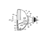
図1及び図2に示すように、陰極線管装置、例えばセルフコンバージェンス方式のインライン型カラー陰極線管装置は、ガラス製の真空外囲器10を備えている。この真空外囲器10は、周縁にスカート部2を有したほぼ矩形状のパネル1と、パネル1のスカート部2に連接されたファンネル4と、ファンネル4の径小端部に連接された円筒状のネック3と、を有している。パネル1は、略矩形状の有効部1Aを有している。有効部1Aは、その曲率半径が10000mm以上となるよう略平坦に形成されている。
【0019】
また、このパネル1は、その内面に配置された、赤、緑、青にそれぞれ発光する複数の蛍光体層及び遮光層からなる蛍光体スクリーン12を備えている。偏向ヨーク14を装着するためのヨーク装着部15は、ネック3からファンネル4にわたる真空外囲器10の外周に形成されている。
【0020】
インライン型電子銃構体16は、ネック3内に配設されている。このインライン型電子銃構体16は、蛍光体スクリーン12の蛍光体層に向けて同一水平面を通る水平軸方向に一列配置された3電子ビーム20R、20G、20Bを放出する。
【0021】
偏向ヨーク14は、電子銃構体16から放出された3電子ビーム20R、20G、20Bを水平軸方向及び垂直軸方向に偏向する非斉一な偏向磁界を発生する。この偏向磁界は、ピンクッション型の水平偏向磁界と、バレル型の垂直偏向磁界とを組み合わせることによって形成される。これにより、格別の補正手段を要することなく、画面全体にわたり、一列配置の3電子ビームをコンバージェンスすることができる。
【0022】
色選別機能を有するシャドウマスク18は、電子銃構体16と蛍光体スクリーン12との間におけるパネル1の内側に配置されている。このシャドウマスク18は、矩形枠状のマスクフレーム17によって支持されている。このシャドウマスク18は、電子銃構体16から放出された3電子ビーム20R、20G、20Bを整形し、それぞれの電子ビームを特定の色の蛍光体層に到達させるよう色選別を行う。
【0023】
なお、真空外囲器10は、ネック3と同軸で蛍光体スクリーン12の中心を通って延びた軸を管軸(中心軸)Z、管軸Zと直交して延びた軸を水平軸(長軸)X、管軸Z及び水平軸Xと直交して延びた軸を垂直軸(短軸)Yとしている。
【0024】
このような構成のカラー陰極線管装置では、電子銃構体16から放出された3電子ビーム20R、20G、20Bを偏向ヨーク14から発生した非斉一な偏向磁界により水平軸方向及び垂直軸方向に偏向し、シャドウマスク18を介して、蛍光体スクリーン12を水平軸方向及び垂直軸方向に走査することにより、カラー画像を表示する。
【0025】
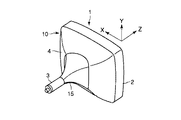
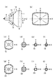
図2及び図3の(b)に示すように、真空外囲器10のパネル1は、水平軸Xと垂直軸Yとで規定されるXY平面内の断面において、ほぼ矩形状に形成されている。また、図2及び図3の(a)乃至(f)に示すように、真空外囲器10のヨーク装着部15は、XY平面内の断面において、水平軸Xに対向して、ネック3側からパネル1方向に向かってほぼ円形を保った形状に形成されているとともに、垂直軸Yに対向して、ネック3側からパネル1方向に向かって円形状から次第にほぼ直線形状に変化するような形状に形成されている((f)→(e)→(d)→(c))。
【0026】
なお、このヨーク装着部15において、水平軸Xに対向した円形状は、外方に突出するような曲線形状であれば単一の曲率半径を有するように形成しても良いし、複数の曲率半径を組み合わせて形成しても良い。また、垂直軸Yに対向した直線形状は、完全な直線でなくても、外方に若干突出するような曲線形状であっても良い。さらに、これら円形状と直線形状とが接合する対角軸近傍では、角型であっても円形状であっても良い。
【0027】
すなわち、ヨーク装着部15は、水平軸Xと管軸Zとで規定されるXZ平面に対向してほぼ円錐面状に形成されており、ほぼ円錐台形状をなしている。また、このヨーク装着部15は、垂直軸Yと管軸Zとで規定されるYZ平面に対向してほぼ平坦状に形成されており、ほぼ角錐台形状をなしている。
【0028】
このような形状を有するヨーク装着部15によれば、水平軸X方向の径を小さくすることができるため、偏向ヨーク14の水平偏向コイル30a、30bを電子ビームに近づけて配置することができ、電子ビームを効率よく偏向し、偏向電力を低減することが可能となる。また、このような形状を有するヨーク装着部15によれば、垂直軸Y方向の径を拡大することができるため、垂直方向に偏向された電子ビームのヨーク装着部15内面への衝突を防止することができる。
【0029】
すなわち、図4の(a)に示すように、ほぼ角錐台形状のヨーク装着部15では、垂直軸Y方向、特に対角軸D方向に偏向された電子ビーム群20のうち、一部の電子ビームがXZ平面に対向するヨーク装着部内面に衝突するおそれがある。これに対して、図4の(b)に示すように、上述した形状を有するヨーク装着部15では、垂直軸Y方向の径が拡大されたため、対角軸D方向に偏向された電子ビーム群20のヨーク装着部内面への衝突を防止することができる。このため、ヨーク装着部内面に衝突していた電子ビームによる蛍光体層の不所望な発光を抑制することが可能となる。
【0030】
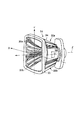
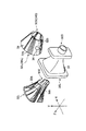
一方、図1、及び図5乃至図7に示すように、偏向ヨーク14は、一対の水平偏向コイル30a、30bと、一対の垂直偏向コイル32a、32bと、セパレータ33と、磁性体コア34と、を備えている。
【0031】
セパレータ33は、合成樹脂等によって形成されている。このセパレータ33は、ヨーク装着部15の外面形状とほぼ相似形に形成されている。すなわち、セパレータ33は、管軸Zに沿った一端側(パネル側)に径大部33Lを有するとともに管軸Zに沿った他端側(ネック側)に径小部33Sを有している。
【0032】
また、図3の(g)乃至(j)に示すように、セパレータ33は、XY平面内の断面において、水平軸Xに対向して、ネック3側からパネル1方向に向かってほぼ円形を保った形状に形成されているとともに、垂直軸Yに対向して、ネック3側からパネル1方向に向かって円形状から次第にほぼ直線形状に変化するような形状に形成されている((j)→(i)→(h)→(g))。つまり、このセパレータ33は、XZ平面に対向してほぼ円錐面状に形成されており、ほぼ円錐台形状をなしている。また、このセパレータ33は、YZ平面に対向してほぼ平坦状に形成されており、ほぼ角錐台形状をなしている。
【0033】
なお、このセパレータ33において、水平軸Xに対向した円形状は、外方に突出するような曲線形状であれば単一の曲率半径を有するように形成しても良いし、複数の曲率半径を組み合わせて形成しても良い。また、垂直軸Yに対向した直線形状は、完全な直線でなくても、外方に若干突出するような曲線形状であっても良い。さらに、これら円形状と直線形状とが接合する対角軸近傍では、角型であっても円形状であっても良い。
【0034】
磁性体コア34は、ほぼ円錐台形状に形成されている。すなわち、この磁性体コア34は、管軸Zに沿った一端側に径大部34Lを有するとともに管軸Zに沿った他端側に径小部34Sを有している。この磁性体コア34は、XZ平面に沿って2分割可能に形成され、固定片36によって互いに固定されている。この磁性体コア34は、セパレータ33の外側を取り囲むように管軸Zと同軸的に設けられている。
【0035】
水平偏向コイル30a、30bは、例えばピンクッション型の水平偏向磁界を発生し、電子ビームを水平軸X方向に偏向する。一対の水平偏向コイル30a、30bは、それぞれサドル型のコイルである。これらの水平偏向コイル30a、30bは、セパレータ33の内面に沿って管軸Zに対して対称に取り付けられている。
【0036】
すなわち、これらの水平偏向コイル30a、30bは、管軸Zを含むXZ平面に対して対称に配置される。これにより、これらの水平偏向コイル30a、30bは、合わせてほぼセパレータ33と相似形を形成する。つまり、これらの水平偏向コイル30a、30bは、XZ平面に対向してほぼ円錐面状に形成されており、ほぼ円錐台形状をなしている。また、これらの水平偏向コイル30a、30bは、YZ平面に対向してほぼ平坦状に形成されており、ほぼ角錐台形状をなしている。さらに、これらの水平偏向コイル30a、30bは、管軸Zに沿った一端側に径大部30Lを有するとともに管軸Zに沿った他端側に径小部30Sを有している。
【0037】
垂直偏向コイル32a、32bは、例えばバレル型の垂直偏向磁界を発生し、電子ビームを垂直軸Y方向に偏向する。一対の垂直偏向コイル32a、32bは、それぞれトロイダル型のコイルである。これらの垂直偏向コイル32a、32bは、セパレータの外面に装着される磁性体コア34にコイル線をトロイダル巻きすることによって形成されている。すなわち、これらの垂直偏向コイル32a、32bは、管軸Zを含むXZ平面に対して対称に配置される。また、これらの垂直偏向コイル32a、32bは、管軸Zに沿った一端側に径大部32Lを有するとともに管軸Zに沿った他端側に径小部32Sを有している。
【0038】
また、一対の水平偏向コイル30a、30bは、管軸Z方向に沿った両端部のうち、少なくとも一方の端部がベンドレス形状である。このベンドレス形状は、ベンド部を設けた場合に比べて使用する電力量が少なくなるので、偏向電力低減の面で望ましい形状である。
【0039】
偏向ヨーク14において、ほぼ円錐台状の磁性体コア34の蛍光体スクリーン側端すなわち径大部34Lにおける内径及び外径は、水平偏向コイル30a、30bに対する最適な位置及び管軸方向の長さを考慮して、水平偏向コイル30a、30bの径大部30Lにおける対角軸D方向に沿った径に応じて決められている。すなわち、水平偏向コイル30a、30bがYZ平面に対向してほぼ角錐台形状に形成されるとともにXZ平面に対向してほぼ円錐台形状に形成され、磁性体コア34がほぼ円錐台形状に形成された場合、磁性体コア34の内面は、各水平偏向コイル30a、30bの対角軸D部分に最も接近して位置する。
【0040】
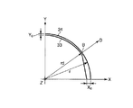
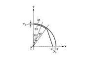
そこで、図8に示すような磁性体コア34の径大部34LにおけるXY平面において、磁性体コア34の曲率半径rは、水平偏向コイルの対角軸端に向かう対角軸Dとが交差する位置Bにおけるセパレータ33の径rdよりもやや大きく設定されている。また、この磁性体コア34の径小部34Sにおける内面及び外形は、セパレータ33の径小部33Sがほぼ円形となっていることから、その円の半径に応じて決められている。すなわち、図9に示すように、垂直偏向コイル32a、32bを磁性体コア34にトロイダル巻きするための余裕を考慮して、磁性体コア34の径小部34Sの内径及び外形は、セパレータ33の径小部33Sの半径rd、径小部34Sの半径r、及び管軸方向の長さを考慮して、最適な円錐台状に形成されている。図9に示すような磁性体コア34の径小部34SにおけるXY平面において、磁性体コア34の曲率半径rは、セパレータ33の曲率半径rdよりも大きく設定されている。
【0041】
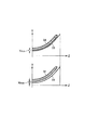
また、図8及び図10に示すように、管軸Z方向のいずれの位置におけるXY断面でも(図9に示した磁性体コア34の径小部34Sに相当する断面を除く)、水平軸X上における磁性体コア34とセパレータ33との間隔X0が垂直軸Y上における磁性体コア34とセパレータ33との間隔Y0より大きくなっている。
【0042】
すなわち、水平軸X近傍では、偏向電力の低減を考慮して水平偏向コイルを電子ビームに近づけるために、ヨーク装着部15をほぼ平坦な形状とするとともにセパレータ33もほぼ平坦な形状として水平方向径を縮小しているのに対して、円筒状の磁性体コア34を適用している。このため、水平軸X上において、磁性体コア34とセパレータ33との間隔X0は、大きく設定される。
【0043】
また、垂直軸Y近傍では、垂直軸Y方向に偏向された電子ビームのヨーク装着部15内面への衝突を防止するために、ヨーク装着部15をほぼ円錐面形状とするとともにセパレータ33もほぼ円錐面形状として垂直方向径を拡大している。このような形状のセパレータ33に円筒状の磁性体コア34を適用したことにより、垂直軸Y上において、磁性体コア34とセパレータ33との間隔Y0は、小さく設定される。
【0044】
これらを考慮して、XZ平面に対向するセパレータ33と磁性体コア34との垂直軸Yに沿った最小間隔Yminと、YZ平面に対向するセパレータ33と磁性体コア34との水平軸Xに沿った最大間隔Xmaxとの関係が
Xmax≧1.5×Ymin
を満たすように設定される。
【0045】
次に、他の実施形態について説明する。
【0046】
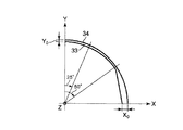
パネル1の有効部1Aにおけるアスペクト比が16:9のカラー陰極線管装置において、電子ビームがヨーク装着部に衝突しやすい位置は、図11に示すように、XY平面において、垂直軸Yとのなす角度が25°以上50°以下の範囲内に相当する。このため、この範囲内におけるXZ平面に対向するセパレータ33と磁性体コア34との垂直軸Yに沿った最小間隔Yminと、YZ平面に対向するセパレータ33と磁性体コア34との水平軸Xに沿った最大間隔Xmaxとの関係が
Xmax≧1.5×Ymin
を満たすように設定されることが望ましい。これにより、水平偏向コイルによる偏向電力の低減を図ることができるとともに、電子ビームのヨーク装着部への衝突を防止することができる。
【0047】
パネル1の有効部1Aにおけるアスペクト比が4:3のカラー陰極線管装置において、電子ビームがヨーク装着部に衝突しやすい位置は、図12に示すように、XY平面において、垂直軸Yとのなす角度が25°以上40°以下の範囲内に相当する。このため、この範囲内におけるXZ平面に対向するセパレータ33と磁性体コア34との垂直軸Yに沿った最小間隔Yminと、YZ平面に対向するセパレータ33と磁性体コア34との水平軸Xに沿った最大間隔Xmaxとの関係が
Xmax≧1.5×Ymin
を満たすように設定されることが望ましい。これにより、水平偏向コイルによる偏向電力の低減を図ることができるとともに、電子ビームのヨーク装着部への衝突を防止することができる。
【0048】
以上説明したように、この実施の形態に係るカラー陰極線管装置によれば、真空外囲器のヨーク装着部、偏向ヨークのセパレータ及び水平偏向コイルは、YZ平面に対向する水平軸近傍をほぼ角錐台形状とし、XZ平面に対向する垂直軸近傍をほぼ円錐台形状としている。このため、電子ビームの偏向角が最も大きくなる対角軸方向の径は、円錐台形状とほぼ同等であって、水平軸方向の径を縮小することができる。これにより、水平偏向コイルを真空外囲器内の電子ビームに近づけることができる。したがって、電子ビームを効率良く偏向することができ、偏向ヨークの偏向電力を低減することが可能となる。
【0049】
また、角錐台形状と比較して、垂直軸方向の径を拡大することができる。これにより、対角軸方向及び垂直軸方向に偏向された電子ビームのヨーク装着部への衝突を抑制することができる。したがって、蛍光体層の不所望な発光を防止することができ、表示品位を向上することが可能となる。
【0050】
さらに、電子ビームがヨーク装着部に長時間に亘って衝突することによるガラスの過熱を抑制することができ、真空外囲器の爆縮を防止することができる。したがって、信頼性を向上することが可能となる。
【0051】
またさらに、上述した実施の形態による偏向ヨークは、ほぼ円錐台形状の磁性体コアを採用したことにより、容易に製造することができ、製造コストの低減を図ることが可能となる。
【0052】
なお、この発明は上述した実施の形態に限定されることなく、この発明の範囲内で種々変形可能である。例えば、この発明は、垂直方向が完全に円錐形状をしている必要は無く、ヨーク装着部の電子ビームがほぼ衝突しない位置ではどのような形状をしていても良い。さらに、この発明は、カラー陰極線管装置に限らず、モノクロの陰極線管装置にも適用可能であり、また、垂直偏向コイルは、トロイダル型に限らず、サドル型であっても適用可能である。
【0053】
【発明の効果】
以上説明したように、この発明によれば、偏向電力及び製造コストを低減しつつ、表示品位を向上することができ、しかも信頼性の高い偏向ヨーク及びこれを備えた陰極線管装置を提供することができる。
【図面の簡単な説明】
【図1】図1は、この発明の一実施の形態に係るカラー陰極線管装置の構造を一部破断して示す平面図である。
【図2】図2は、図1に示したカラー陰極線管装置の真空外囲器の背面側の構造を概略的に示す斜視図である。
【図3】図3の(a)乃至(f)は、図2に示した真空外囲器の側面図及び真空外囲器各部を示す断面図であり、(a)は真空外囲器の側面図、(b)は(a)における線B−Bに沿った断面図、(c)は(a)における線C−Cに沿った断面図、(d)は(a)における線D−Dに沿った断面図、(d)は(a)における線E−Eに沿った断面図、(f)は(a)における線F−Fに沿った断面図であり、(g)は(a)における線C−Cに沿ったセパレータの断面図、(h)は(a)における線D−Dに沿ったセパレータの断面図、(i)は(a)における線E−Eに沿ったセパレータの断面図、(j)は(a)における線F−Fに沿ったセパレータの断面図である。
【図4】図4の(a)は、ほぼ角錐台形状のヨーク装着部における電子ビーム群との位置関係を説明するための図であり、図4の(b)は、この実施の形態に係るヨーク装着部における電子ビーム群との位置関係を説明するための図である。
【図5】図5は、図1に示したカラー陰極線管装置に適用される偏向ヨークの構造を概略的に示す斜視図である。
【図6】図6の(a)は、図5に示した偏向ヨークのパネル側から見た正面図であり、図6の(b)は、図5に示した偏向ヨークの側面図である。
【図7】図7は、図5に示した偏向ヨークの分解斜視図である。
【図8】図8は、この実施の形態に係る磁性体コアの径大部におけるセパレータとの位置関係を示す図である。
【図9】図9は、この実施の形態に係る磁性体コアの径小部におけるセパレータとの位置関係を示す図である。
【図10】図10は、磁性体コアとセパレータとの垂直軸に沿った最小間隔と水平軸に沿った最大間隔とを説明するための図である。
【図11】図11は、他の実施の形態に係る磁性体コアの径大部におけるセパレータとの位置関係を示す図である。
【図12】図12は、他の実施の形態に係る磁性体コアの径大部におけるセパレータとの位置関係を示す図である。
【符号の説明】
1…パネル、3…ネック、4…ファンネル、10…真空外囲器、12…蛍光体スクリーン、14…偏向ヨーク、15…ヨーク装着部、16…電子銃構体、18…シャドウマスク、20(R、G、B)…電子ビーム、30a、30b…水平偏向コイル、32a、32b…垂直偏向コイル、33…セパレータ、34…磁性体コア[0001]
TECHNICAL FIELD OF THE INVENTION
The present invention relates to a deflection yoke and a cathode ray tube device including the same, and more particularly, to a structure of a separator constituting the deflection yoke.
[0002]
[Prior art]
In a color cathode ray tube, the deflection yoke is a large power consumption source. Therefore, in order to reduce power consumption, it is important to reduce the power consumption of the deflection yoke. Therefore, in recent years, for the purpose of reducing deflection power, a cathode ray tube device has been proposed in which a funnel yoke mounting portion has a truncated pyramid shape that gradually changes from a circular shape to a substantially rectangular shape from a neck side to a panel side.
[0003]
According to such a configuration, the diameter in the diagonal direction where the deflection angle of the electron beam is the largest is the same as that of the frustum-shaped yoke mounting portion, and the diameter in the long axis (horizontal axis) and the short axis (vertical axis) The diameter in the (axial) direction can be reduced. As a result, the horizontal deflection coil and the vertical deflection coil constituting the deflection yoke can be brought closer to the electron beam passage area in the yoke mounting portion, and the deflection power can be reduced by efficiently deflecting the electron beam. .
[0004]
The deflection yoke mounted on the frustum-shaped pyramid-shaped yoke mounting portion includes a saddle / saddle type deflection yoke in which the horizontal deflection coil and the vertical deflection coil are both saddle types, and a saddle type horizontal deflection coil and a toroidal type vertical deflection coil. Various types, such as a semi-toroidal deflection yoke, are proposed (for example, see Patent Document 1). For example, a saddle / saddle-type deflection yoke disclosed in
[0005]
The semi-toroidal deflection yoke has a structure in which a horizontal deflection coil is disposed inside a magnetic core and a vertical deflection coil is directly wound around the magnetic core. For this reason, the magnetic core itself becomes large, and the deflection power tends to increase.
[0006]
Further, the saddle / saddle type deflection yoke can reduce the deflection power more than the semi-toroidal type deflection yoke, and further reduce the deflection power by forming the magnetic core into a truncated pyramid shape. it can. However, it is difficult to manufacture a frustum-shaped magnetic core, and it is also difficult to toroidally wind a vertical deflection coil around a frustum-shaped magnetic core. Therefore, the manufacturing cost of the deflection yoke is increased, and versatility is lacking.
[0007]
In order to solve such a problem, a magnetic core having a truncated cone shape and a vertical deflection coil are combined, and the horizontal deflection coil is formed into a pyramid shape wound in a saddle shape, thereby reducing deflection power and reducing manufacturing costs. We are trying to reduce it.
[0008]
[Patent Document 1]
JP-A-11-265666
[Problems to be solved by the invention]
A deflection yoke in which a frustum-shaped magnetic core and a vertical deflection coil are combined and the horizontal deflection coil is formed in a pyramid shape wound in a saddle shape is particularly effective in reducing the horizontal deflection power. However, since the vertical direction of the deflection yoke has a pyramid shape and the vertical direction of the funnel yoke mounting portion has a pyramid shape, the electron beam deflected in the vertical direction may collide with the inner surface of the yoke mounting portion.
[0010]
As described above, the electron beam that collides with the inner surface of the yoke mounting portion and bounces off, and the secondary electrons emitted by the electron beam colliding with the inner surface of the yoke mounting portion collide with the phosphor screen on the inner surface of the panel. In such a case, the unwanted phosphor layer emits light. Therefore, there is a problem that display quality is deteriorated. Further, if the electron beam keeps colliding with the inner surface of the yoke mounting portion, the yoke mounting portion is overheated, and the funnel made of glass may be imploded, leading to a decrease in reliability.
[0011]
SUMMARY OF THE INVENTION The present invention has been made in consideration of the above-described problems, and has as its object to improve the display quality while reducing deflection power and manufacturing cost, and to provide a highly reliable deflection yoke. Provided is a cathode ray tube device provided with the same.
[0012]
[Means for Solving the Problems]
The deflection yoke according to the first aspect of the present invention includes:
In a coordinate system formed by a horizontal axis X, a vertical axis Y orthogonal to the horizontal axis X, and a central axis Z orthogonal to the horizontal axis X and the vertical axis Y,
It is provided coaxially with the central axis Z, is formed in a substantially flat shape opposite to a YZ plane defined by the vertical axis Y and the central axis Z, and has the horizontal axis X and the central axis Z. A separator formed in a substantially conical shape facing the XZ plane defined by:
A pair of saddle-type horizontal deflection coils provided symmetrically with respect to the central axis and arranged inside the separator,
A substantially frustoconical magnetic core, which is provided coaxially with the central axis and is disposed outside the separator,
A pair of vertical deflection coils are provided symmetrically with respect to the central axis and arranged outside the separator,
A minimum distance Ymin between the separator and the magnetic core facing the XZ plane along the vertical axis Y, and a maximum distance along the horizontal axis X between the separator and the magnetic core facing the YZ plane. The relation with the interval Xmax is Xmax ≧ 1.5 × Ymin
Is satisfied.
[0013]
A cathode ray tube device according to a second aspect of the present invention comprises:
A vacuum envelope having a panel having a phosphor screen on the inner surface,
An electron gun assembly disposed in the vacuum envelope and emitting an electron beam toward the phosphor screen;
A deflection yoke mounted outside the vacuum envelope and deflecting an electron beam emitted from the electron gun assembly in a horizontal axis direction and a vertical axis direction;
In a coordinate system formed by a horizontal axis X, a vertical axis Y orthogonal to the horizontal axis X, and a tube axis Z orthogonal to the horizontal axis X and the vertical axis Y,
The vacuum envelope includes a yoke mounting portion on which the deflection yoke is mounted, and the yoke mounting portion has a substantially flat shape facing a YZ plane defined by the vertical axis Y and the tube axis Z. And is formed in a substantially conical shape facing an XZ plane defined by the horizontal axis X and the tube axis Z,
The deflection yoke,
A separator that is provided coaxially with the pipe axis Z, is formed in a substantially flat shape facing the YZ plane, and is formed in a substantially conical shape facing the XZ plane;
A pair of saddle-type horizontal deflection coils provided symmetrically with respect to the tube axis and arranged inside the separator,
A substantially frustoconical magnetic core that is provided coaxially with the tube axis and is disposed outside the separator,
A pair of vertical deflection coils are provided symmetrically with respect to the tube axis and arranged outside the separator,
A minimum distance Ymin between the separator and the magnetic core facing the XZ plane along the vertical axis Y, and a maximum distance along the horizontal axis X between the separator and the magnetic core facing the YZ plane. The relation with the interval Xmax is Xmax ≧ 1.5 × Ymin
Is satisfied.
[0014]
According to the deflection yoke having the above-described configuration and the cathode ray tube device having the deflection yoke, the yoke mounting portion of the vacuum envelope to which the deflection yoke is mounted has a substantially truncated pyramid shape facing the YZ plane, and is formed in the XZ plane. It has a substantially frusto-conical shape opposite to it. The separator of the deflection yoke mounted on the yoke mounting portion is formed in a shape similar to the yoke mounting portion, has a substantially truncated pyramid shape facing the YZ plane, and has a substantially truncated cone shape facing the XZ plane. It has a shape. The pair of horizontal deflection coils are arranged inside the separator, and are formed substantially similar to the separator. The magnetic core disposed outside the separator has a substantially truncated cone shape, and a pair of vertical deflection coils are directly wound.
[0015]
As described above, by forming the yoke mounting portion, the separator, and the horizontal deflection coil in a substantially truncated pyramid shape facing the YZ plane, the electron beam can be efficiently deflected, and the deflection power can be reduced. It becomes. Also, by making the yoke mounting portion, the separator, and the horizontal deflection coil into a substantially truncated cone shape facing the YZ plane, the diameter in the vertical direction is enlarged, and the electron beam deflected in the vertical direction is applied to the inner surface of the yoke mounting portion. Collision hardly occurs, and it becomes possible to suppress undesired light emission of the phosphor layer. Furthermore, since the collision of the electron beam with the yoke mounting portion can be prevented, the yoke mounting portion is not overheated, and implosion of the vacuum envelope can be prevented, thereby improving reliability. be able to.
[0016]
In addition, the above-described deflection yoke can be easily manufactured by adopting the substantially frusto-conical magnetic core, so that the manufacturing cost can be reduced.
[0017]
BEST MODE FOR CARRYING OUT THE INVENTION
Hereinafter, a deflection yoke according to an embodiment of the present invention and a cathode ray tube device including the same will be described with reference to the drawings.
[0018]
As shown in FIGS. 1 and 2, a cathode ray tube device, for example, a self-convergence type in-line color cathode ray tube device includes a
[0019]
Further, the
[0020]
The in-line type
[0021]
The
[0022]
The
[0023]
The
[0024]
In the color cathode ray tube device having such a configuration, the three
[0025]
As shown in FIGS. 2 and 3B, the
[0026]
In the
[0027]
That is, the
[0028]
According to the
[0029]
That is, as shown in FIG. 4A, in the substantially frustum-shaped
[0030]
On the other hand, as shown in FIGS. 1 and 5 to 7, the
[0031]
The
[0032]
Further, as shown in FIGS. 3G to 3J, the
[0033]
In this
[0034]
The
[0035]
The horizontal deflection coils 30a and 30b generate, for example, a pincushion-type horizontal deflection magnetic field, and deflect the electron beam in the horizontal axis X direction. Each of the pair of horizontal deflection coils 30a and 30b is a saddle type coil. These horizontal deflection coils 30a and 30b are mounted symmetrically with respect to the tube axis Z along the inner surface of the
[0036]
That is, these horizontal deflection coils 30a and 30b are arranged symmetrically with respect to the XZ plane including the tube axis Z. Thus, the horizontal deflection coils 30a and 30b together form a shape substantially similar to the
[0037]
The vertical deflection coils 32a and 32b generate, for example, a barrel-type vertical deflection magnetic field, and deflect the electron beam in the vertical axis Y direction. Each of the pair of vertical deflection coils 32a and 32b is a toroidal coil. These vertical deflection coils 32a and 32b are formed by toroidally winding a coil wire around a
[0038]
Further, the pair of horizontal deflection coils 30a and 30b have at least one end in a bendless shape among both ends along the tube axis Z direction. This bendless shape is a desirable shape in terms of reducing deflection power because the amount of power used is smaller than when a bend portion is provided.
[0039]
In the
[0040]
Therefore, on the XY plane of the large diameter portion 34L of the
[0041]
As shown in FIGS. 8 and 10, the XY cross section at any position in the tube axis Z direction (excluding the cross section corresponding to the
[0042]
That is, in the vicinity of the horizontal axis X, in order to make the horizontal deflection coil closer to the electron beam in consideration of the reduction of the deflection power, the
[0043]
In the vicinity of the vertical axis Y, in order to prevent the electron beam deflected in the vertical axis Y direction from colliding with the inner surface of the
[0044]
In consideration of these, the minimum distance Ymin between the
Is set to satisfy
[0045]
Next, another embodiment will be described.
[0046]
In the color cathode ray tube device having an
It is desirable to be set to satisfy the following. Thus, the deflection power by the horizontal deflection coil can be reduced, and the collision of the electron beam with the yoke mounting portion can be prevented.
[0047]
In a color cathode ray tube device having an
It is desirable to be set to satisfy the following. Thus, the deflection power by the horizontal deflection coil can be reduced, and the collision of the electron beam with the yoke mounting portion can be prevented.
[0048]
As described above, according to the color cathode ray tube device of this embodiment, the yoke mounting portion of the vacuum envelope, the separator of the deflection yoke, and the horizontal deflection coil are substantially pyramidal in the vicinity of the horizontal axis facing the YZ plane. It has a trapezoidal shape, and the vicinity of the vertical axis facing the XZ plane has a substantially truncated cone shape. For this reason, the diameter in the diagonal axis direction at which the deflection angle of the electron beam is the largest is almost equal to the truncated cone shape, and the diameter in the horizontal axis direction can be reduced. This allows the horizontal deflection coil to approach the electron beam in the vacuum envelope. Therefore, the electron beam can be efficiently deflected, and the deflection power of the deflection yoke can be reduced.
[0049]
Further, the diameter in the vertical axis direction can be enlarged as compared with the truncated pyramid shape. Thereby, collision of the electron beam deflected in the diagonal axis direction and the vertical axis direction with the yoke mounting portion can be suppressed. Therefore, it is possible to prevent undesired light emission of the phosphor layer, and it is possible to improve display quality.
[0050]
Furthermore, it is possible to suppress overheating of the glass due to the electron beam colliding with the yoke mounting portion for a long time, and to prevent implosion of the vacuum envelope. Therefore, it is possible to improve the reliability.
[0051]
Furthermore, since the deflection yoke according to the above-described embodiment employs a magnetic core having a substantially frustoconical shape, it can be easily manufactured, and the manufacturing cost can be reduced.
[0052]
The present invention is not limited to the above-described embodiment, but can be variously modified within the scope of the present invention. For example, in the present invention, it is not necessary that the vertical direction be completely conical, and any shape may be used in the yoke mounting portion at a position where the electron beam hardly collides. Further, the present invention is applicable not only to a color cathode ray tube device but also to a monochrome cathode ray tube device, and the vertical deflection coil is applicable not only to a toroidal type but also to a saddle type.
[0053]
【The invention's effect】
As described above, according to the present invention, it is possible to provide a deflection yoke that can improve display quality while reducing deflection power and manufacturing cost, and that has high reliability and a cathode ray tube device including the same. Can be.
[Brief description of the drawings]
FIG. 1 is a partially cutaway plan view showing a structure of a color cathode ray tube device according to an embodiment of the present invention.
FIG. 2 is a perspective view schematically showing a structure on the back side of a vacuum envelope of the color cathode ray tube device shown in FIG. 1;
3 (a) to 3 (f) are a side view of the vacuum envelope shown in FIG. 2 and a cross-sectional view showing each part of the vacuum envelope, and FIG. Side view, (b) is a cross-sectional view along line BB in (a), (c) is a cross-sectional view along line CC in (a), (d) is line D- in (a) (D) is a cross-sectional view along line EE in (a), (f) is a cross-sectional view along line FF in (a), and (g) is ( (a) is a sectional view of the separator along the line CC in (a), (h) is a sectional view of the separator along the line DD in (a), and (i) is a line along the line EE in (a). (J) is a cross-sectional view of the separator along line FF in (a).
FIG. 4A is a diagram for explaining a positional relationship with an electron beam group in a substantially frustum-shaped yoke mounting portion, and FIG. 4B is a diagram illustrating this embodiment; It is a figure for explaining a positional relationship with an electron beam group in such a yoke mounting part.
FIG. 5 is a perspective view schematically showing a structure of a deflection yoke applied to the color cathode ray tube device shown in FIG.
6A is a front view of the deflection yoke shown in FIG. 5 as viewed from the panel side, and FIG. 6B is a side view of the deflection yoke shown in FIG. .
FIG. 7 is an exploded perspective view of the deflection yoke shown in FIG.
FIG. 8 is a diagram showing a positional relationship between a large diameter portion of the magnetic core and the separator according to the embodiment;
FIG. 9 is a diagram illustrating a positional relationship between a small-diameter portion of the magnetic core and the separator according to the embodiment;
FIG. 10 is a diagram for explaining a minimum distance between a magnetic core and a separator along a vertical axis and a maximum distance along a horizontal axis.
FIG. 11 is a diagram illustrating a positional relationship between a large diameter portion of a magnetic core and a separator according to another embodiment.
FIG. 12 is a diagram illustrating a positional relationship between a large diameter portion of a magnetic core and a separator according to another embodiment.
[Explanation of symbols]
DESCRIPTION OF
Claims (7)
前記中心軸Zと同軸的に設けられ、前記垂直軸Yと前記中心軸Zとで規定されるYZ平面に対向してほぼ平坦状に形成されるとともに、前記水平軸Xと前記中心軸Zとで規定されるXZ平面に対向してほぼ円錐面状に形成されたセパレータと、
前記中心軸に対して対称に設けられているとともに前記セパレータの内側に配置された一対のサドル型の水平偏向コイルと、
前記中心軸と同軸的に設けられているとともに前記セパレータの外側に配置されたほぼ円錐台形状の磁性体コアと、
前記中心軸に対して対称に設けられているとともに前記セパレータの外側に配置された一対の垂直偏向コイルと、を備え、
前記XZ平面に対向する前記セパレータと前記磁性体コアとの前記垂直軸Yに沿った最小間隔Yminと、前記YZ平面に対向する前記セパレータと前記磁性体コアとの前記水平軸Xに沿った最大間隔Xmaxとの関係が
Xmax≧1.5×Ymin
を満たすことを特徴とする偏向ヨーク。In a coordinate system formed by a horizontal axis X, a vertical axis Y orthogonal to the horizontal axis X, and a central axis Z orthogonal to the horizontal axis X and the vertical axis Y,
It is provided coaxially with the central axis Z, is formed in a substantially flat shape opposite to a YZ plane defined by the vertical axis Y and the central axis Z, and has the horizontal axis X and the central axis Z. A separator formed in a substantially conical shape facing the XZ plane defined by:
A pair of saddle-type horizontal deflection coils provided symmetrically with respect to the central axis and arranged inside the separator,
A substantially frustoconical magnetic core, which is provided coaxially with the central axis and is disposed outside the separator,
A pair of vertical deflection coils are provided symmetrically with respect to the central axis and arranged outside the separator,
A minimum distance Ymin between the separator and the magnetic core facing the XZ plane along the vertical axis Y, and a maximum distance along the horizontal axis X between the separator and the magnetic core facing the YZ plane. The relation with the interval Xmax is Xmax ≧ 1.5 × Ymin
A deflection yoke characterized by satisfying the following.
Xmax≧1.5×Ymin
を満たすことを特徴とする請求項1に記載の偏向ヨーク。In an XY plane defined by the horizontal axis X and the vertical axis Y, the relationship between the maximum interval Xmax and the minimum interval Ymin in the range where the angle between the vertical axis Y and the vertical axis Y ranges from 25 ° to 50 °. ,
Xmax ≧ 1.5 × Ymin
The deflection yoke according to claim 1, wherein
前記真空外囲器内に配設され、前記蛍光体スクリーンに向けて電子ビームを放出する電子銃構体と、
前記真空外囲器の外側に装着され、前記電子銃構体から放出された電子ビームを水平軸方向及び垂直軸方向に偏向する偏向ヨークと、を備えた陰極線管装置において、
水平軸Xと、前記水平軸Xと直交する垂直軸Yと、前記水平軸X及び前記垂直軸Yと直交する管軸Zとがなす座標系において、
前記真空外囲器は、前記偏向ヨークが装着されるヨーク装着部を含み、このヨーク装着部は、前記垂直軸Yと前記管軸Zとで規定されるYZ平面に対向してほぼ平坦状に形成されるとともに、前記水平軸Xと前記管軸Zとで規定されるXZ平面に対向してほぼ円錐面状に形成され、
前記偏向ヨークは、
前記管軸Zと同軸的に設けられ、前記YZ平面に対向してほぼ平坦状に形成されるとともに、前記XZ平面に対向してほぼ円錐面状に形成されたセパレータと、
前記管軸に対して対称に設けられているとともに前記セパレータの内側に配置された一対のサドル型の水平偏向コイルと、
前記管軸と同軸的に設けられているとともに前記セパレータの外側に配置されたほぼ円錐台形状の磁性体コアと、
前記管軸に対して対称に設けられているとともに前記セパレータの外側に配置された一対の垂直偏向コイルと、を備え、
前記XZ平面に対向する前記セパレータと前記磁性体コアとの前記垂直軸Yに沿った最小間隔Yminと、前記YZ平面に対向する前記セパレータと前記磁性体コアとの前記水平軸Xに沿った最大間隔Xmaxとの関係が
Xmax≧1.5×Ymin
を満たすことを特徴とする陰極線管装置。A vacuum envelope having a panel having a phosphor screen on the inner surface,
An electron gun assembly disposed in the vacuum envelope and emitting an electron beam toward the phosphor screen;
A deflection yoke mounted outside the vacuum envelope and deflecting an electron beam emitted from the electron gun assembly in a horizontal axis direction and a vertical axis direction;
In a coordinate system formed by a horizontal axis X, a vertical axis Y orthogonal to the horizontal axis X, and a tube axis Z orthogonal to the horizontal axis X and the vertical axis Y,
The vacuum envelope includes a yoke mounting portion on which the deflection yoke is mounted, and the yoke mounting portion has a substantially flat shape facing a YZ plane defined by the vertical axis Y and the tube axis Z. And is formed in a substantially conical shape facing an XZ plane defined by the horizontal axis X and the tube axis Z,
The deflection yoke,
A separator that is provided coaxially with the pipe axis Z, is formed in a substantially flat shape facing the YZ plane, and is formed in a substantially conical shape facing the XZ plane;
A pair of saddle-type horizontal deflection coils provided symmetrically with respect to the tube axis and arranged inside the separator,
A substantially frustoconical magnetic core that is provided coaxially with the tube axis and is disposed outside the separator,
A pair of vertical deflection coils are provided symmetrically with respect to the tube axis and arranged outside the separator,
A minimum distance Ymin between the separator and the magnetic core facing the XZ plane along the vertical axis Y, and a maximum distance along the horizontal axis X between the separator and the magnetic core facing the YZ plane. The relation with the interval Xmax is Xmax ≧ 1.5 × Ymin
A cathode ray tube device characterized by satisfying the following.
Xmax≧1.5×Ymin
を満たすことを特徴とする請求項5に記載の陰極線管装置。In a deflection yoke applied to a cathode ray tube device having an aspect ratio of 16: 9 in an effective portion of the panel, in a XY plane defined by the horizontal axis X and the vertical axis Y, the maximum interval Xmax and the vertical The relationship with the minimum distance Ymin in the range where the angle made with the axis Y is 25 ° or more and 50 ° or less is as follows:
Xmax ≧ 1.5 × Ymin
The cathode ray tube device according to claim 5, wherein the following condition is satisfied.
Xmax≧1.5×Ymin
を満たすことを特徴とする請求項5に記載の陰極線管装置。In the deflection yoke applied to the cathode ray tube device having an aspect ratio of 4: 3 in an effective portion of the panel, in the XY plane defined by the horizontal axis X and the vertical axis Y, the maximum interval Xmax and the vertical The relationship with the minimum distance Ymin in a range where the angle with the axis Y is 25 ° or more and 40 ° or less is as follows:
Xmax ≧ 1.5 × Ymin
The cathode ray tube device according to claim 5, wherein the following condition is satisfied.
Priority Applications (1)
| Application Number | Priority Date | Filing Date | Title |
|---|---|---|---|
| JP2003068067A JP2004281117A (en) | 2003-03-13 | 2003-03-13 | Deflection yoke and cathode ray tube device having the same |
Applications Claiming Priority (1)
| Application Number | Priority Date | Filing Date | Title |
|---|---|---|---|
| JP2003068067A JP2004281117A (en) | 2003-03-13 | 2003-03-13 | Deflection yoke and cathode ray tube device having the same |
Publications (1)
| Publication Number | Publication Date |
|---|---|
| JP2004281117A true JP2004281117A (en) | 2004-10-07 |
Family
ID=33285502
Family Applications (1)
| Application Number | Title | Priority Date | Filing Date |
|---|---|---|---|
| JP2003068067A Pending JP2004281117A (en) | 2003-03-13 | 2003-03-13 | Deflection yoke and cathode ray tube device having the same |
Country Status (1)
| Country | Link |
|---|---|
| JP (1) | JP2004281117A (en) |
-
2003
- 2003-03-13 JP JP2003068067A patent/JP2004281117A/en active Pending
Similar Documents
| Publication | Publication Date | Title |
|---|---|---|
| US6404117B1 (en) | Cathode-ray tube device comprising a deflection yoke with a non-circular core having specified dimensional relationships | |
| JPH10154472A (en) | Cathode ray tube device | |
| KR100495514B1 (en) | Cathode-ray tube | |
| US6307314B1 (en) | Cathode ray tube with deflection yoke including non-circular separator | |
| US6307313B1 (en) | Cathode ray tube apparatus | |
| JP4057887B2 (en) | Deflection yoke and cathode ray tube apparatus provided with deflection yoke | |
| JP2004281117A (en) | Deflection yoke and cathode ray tube device having the same | |
| KR100468135B1 (en) | Deflection yoke and cathode ray tube apparatus having the same | |
| JPH09171782A (en) | Deflection yoke ferrite core for CRT | |
| KR100463718B1 (en) | Color cathode ray tube apparatus | |
| KR100667592B1 (en) | Cathode ray tube | |
| KR100571198B1 (en) | Cathode ray tube | |
| JPH11345579A (en) | Cathode ray tube device and deflection yoke | |
| KR100645781B1 (en) | Cathode ray tube | |
| KR100692043B1 (en) | Cathode ray tube | |
| KR100814873B1 (en) | Deflection Device for Cathode Ray Tubes | |
| KR100626885B1 (en) | Cathode ray tube | |
| JP2002042691A (en) | Deflection yoke and cathode ray tube device having the same | |
| JP2002042692A (en) | Deflection yoke and cathode ray tube device having the same | |
| JP2002329467A (en) | Deflection yoke and cathode ray tube device having the same | |
| JP2002329466A (en) | Deflection yoke and cathode ray tube device having the same | |
| JP2002216667A (en) | Deflection yoke and cathode ray tube device | |
| JP2002289119A (en) | Deflection yoke and cathode ray tube device having the same | |
| JP2001135260A (en) | Cathode ray tube | |
| JP2003242906A (en) | Deflection yoke and cathode ray tube device having the same |