JP2004281174A - Connector locking mechanism - Google Patents
Connector locking mechanism Download PDFInfo
- Publication number
- JP2004281174A JP2004281174A JP2003069499A JP2003069499A JP2004281174A JP 2004281174 A JP2004281174 A JP 2004281174A JP 2003069499 A JP2003069499 A JP 2003069499A JP 2003069499 A JP2003069499 A JP 2003069499A JP 2004281174 A JP2004281174 A JP 2004281174A
- Authority
- JP
- Japan
- Prior art keywords
- cam
- connector
- locked
- upper cam
- contact
- Prior art date
- Legal status (The legal status is an assumption and is not a legal conclusion. Google has not performed a legal analysis and makes no representation as to the accuracy of the status listed.)
- Granted
Links
Images

Classifications
-
- G—PHYSICS
- G05—CONTROLLING; REGULATING
- G05G—CONTROL DEVICES OR SYSTEMS INSOFAR AS CHARACTERISED BY MECHANICAL FEATURES ONLY
- G05G1/00—Controlling members, e.g. knobs or handles; Assemblies or arrangements thereof; Indicating position of controlling members
- G05G1/08—Controlling members for hand actuation by rotary movement, e.g. hand wheels
-
- H—ELECTRICITY
- H01—ELECTRIC ELEMENTS
- H01R—ELECTRICALLY-CONDUCTIVE CONNECTIONS; STRUCTURAL ASSOCIATIONS OF A PLURALITY OF MUTUALLY-INSULATED ELECTRICAL CONNECTING ELEMENTS; COUPLING DEVICES; CURRENT COLLECTORS
- H01R13/00—Details of coupling devices of the kinds covered by groups H01R12/70 or H01R24/00 - H01R33/00
- H01R13/02—Contact members
- H01R13/15—Pins, blades or sockets having separate spring member for producing or increasing contact pressure
- H01R13/18—Pins, blades or sockets having separate spring member for producing or increasing contact pressure with the spring member surrounding the socket
Landscapes
- Physics & Mathematics (AREA)
- General Physics & Mathematics (AREA)
- Engineering & Computer Science (AREA)
- Automation & Control Theory (AREA)
- Details Of Connecting Devices For Male And Female Coupling (AREA)
- Coupling Device And Connection With Printed Circuit (AREA)
Abstract
【課題】衝撃又は振動等が生じても、相手側コネクタとの接続又は非接続の所要の一方の状態を確実に維持できるコネクタのロック機構を提供する。
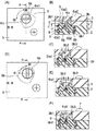
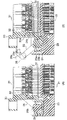
【解決手段】(A),(B)において、ドライバを上カム6aの溝6a1に挿入して、上カムをカバー3の穴3b内方にばね8を圧縮して押し込む。すると、上カムは、(C)の状態に至り、一対の被ロックボス6a2は、カバーの一対のロックボス溝3b3からロック解除される。次に、上カムを90°右回転すると、上カムは、(D),(E)の状態に至る。このとき、上カムの長方形ボス6a3と下カム6bの長方形ボス穴6b1とがはまっているため、下カム6bも90°右回転する。したがって、下カムはアクチュエータをスライドさせ、アクチュエータはソケットコンタクトをピンコンタクトに接触させる。続いて、ドライバを溝から撤去すると、上カムは、ばねの拡張力によって(F)の状態に至る。このとき、各被ロックボスは、カバー3の一対のロックボス溝3b4内に進入する。すなわち、上カムは、回転を制止されてロックされる。
【選択図】 図6Provided is a connector locking mechanism that can reliably maintain a required one of a connection state and a non-connection state with a mating connector even when an impact or vibration occurs.
(A) In (A) and (B), a driver is inserted into a groove 6a1 of an upper cam 6a, and a spring 8 is compressed and pushed into a hole 3b of a cover 3 with the upper cam. Then, the upper cam reaches the state (C), and the pair of locked bosses 6a2 is unlocked from the pair of lock boss grooves 3b3 of the cover. Next, when the upper cam is rotated 90 ° to the right, the upper cam reaches the states (D) and (E). At this time, since the rectangular boss 6a3 of the upper cam and the rectangular boss hole 6b1 of the lower cam 6b are fitted, the lower cam 6b also rotates 90 ° clockwise. Thus, the lower cam slides the actuator, which causes the socket contact to contact the pin contact. Subsequently, when the driver is removed from the groove, the upper cam reaches the state (F) by the expanding force of the spring. At this time, each locked boss enters the pair of lock boss grooves 3b4 of the cover 3. That is, rotation of the upper cam is stopped and locked.
[Selection] Fig. 6
Description
【0001】
【発明の属する技術分野】
本発明は、ZIF(Zero Insertion Force 無挿入力)等のコネクタに関し、特に、スライド操作によって相手側コネクタとの接続と非接続の切替が行われるコネクタにおいて、接続又は非接続の所要の一方の状態を確実に維持することができるロック機構に関する。
【0002】
【従来の技術】
従来のZIFコネクタについて図8を参照して説明する(例えば、特許文献1参照)。図8(A)は非接続状態、図8(B)は接続状態を、それぞれ示す。
【0003】
ZIFコネクタは、ピンコネクタ21とソケットコネクタ31とから構成される。
【0004】
ピンコネクタ21は、多数のピンコンタクト22と、各ピンコンタクト22を保持するベースインシュレータ23と、ベースインシュレータ23上で左右方向にスライド可能なハウジング24と、ハウジング24をスライドさせるレバー25と、レバー25を回転させるスライダ26とから構成される。
【0005】
レバー25は、支点25aを中心として回転可能であり、一端側にカム25bを有し、他端側に円柱状突起25cを有する。
【0006】
スライダ26は、略3角形状の穴26aを有し、穴26aの傾斜面26a1は、レバー25の円柱状突起25cに圧接する。
【0007】
ソケットコネクタ31は、多数のソケットコンタクト32と、各ソケットコンタクト32を保持するインシュレータ33とから構成される。インシュレータ33に設けられた一対の凹部33a(右方のものの図示を省略)は、ハウジング24に設けられた一対の凸部24a(右方のものの図示を省略)にはまる。
【0008】
図8(A)の状態では、各ピンコンタクト22の先端は、各ソケットコンタクト32の二股状の先端の間に挿入されているが、各ピンコンタクト22は、各ソケットコンタクト32に電気的に確実には接触していない。
【0009】
図8(A)の状態において、スライダ26を左方向にスライドさせると、スライダ26の傾斜面26a1は、レバー25の円柱状突起25cを押すので、レバー25は、支点25aを中心として左回転し、図8(B)の状態に至る。このとき、カム25bは、ハウジング24を右方向にスライドさせる。すると、ソケットコネクタ31のインシュレータ33も右方向に移動するので、各ソケットコンタクト32は、各ピンコンタクト22を弾性変形させる。したがって、各ピンコンタクト22は、各ソケットコンタクト32に電気的に確実に接触するため、ピンコネクタ21は、ソケットコネクタ31と接続する。
【0010】
この種のZIFコネクタは、他の文献にも記載されている(例えば、特許文献2参照。)。
【0011】
【特許文献1】
特開2000−306642号公報(第3頁第3欄第48行−第4欄第34行、図7,8)
【0012】
【特許文献2】
特開2000−286025号公報(第4頁第6欄第43行−第6頁第10欄第42行、図1,5,9)
【0013】
【発明が解決しようとする課題】
前記従来のZIFコネクタでは、スライダをスライドすることによって中間機構を介してZIFコネクタの接続と非接続とを切替える。したがって、衝撃又は振動等がZIFコネクタに生じると、ZIFコネクタの接続又は非接続の所要の一方の状態が、確実には維持されない。
【0014】
そこで、本発明は、前記従来のZIFコネクタの欠点を改良し、衝撃又は振動等が生じても、相手側コネクタとの接続又は非接続の所要の一方の状態を確実に維持することができるコネクタのロック機構を提供しようとするものである。
【0015】
【課題を解決するための手段】
本発明は、前記課題を解決するため、次の手段を採用する。
【0016】
1.カムの操作によって、相手側コネクタとの接続と非接続の切替を行うコネクタにおいて、前記カムは、その回転をロックされる被ロック部が設けられた第1のカムと、前記両コネクタの接続と非接続の切替を行うカム部が設けられた第2のカムとから構成され、前記第1のカムは、スライド可能に、かつ、回転可能に前記コネクタのインシュレータに保持され、前記第2のカムは、回転可能に前記インシュレータに保持され、かつ、前記第1のカムの回転に連動して回転し、前記第1のカムと前記第2のカムとは、対向して配設され、弾性部材で離間する方向に常時付勢されることによって、前記第1のカムの被ロック部が前記インシュレータに設けられたロック部にロックされ、前記第1のカムを前記第2のカムに向かってスライドさせてロックを解除した後、前記第1のカムの回転によって、前記両コネクタの接続と非接続の切替を行うコネクタのロック機構。
【0017】
2.前記被ロック部は、位相が180°異なる一対の被ロックボスであり、前記ロック部は、位相が90°異なる二対のロックボス溝である前記1記載のコネクタのロック機構。
【0018】
3.前記弾性部材は、圧縮コイルばねであって、前記第2のカムに設けられた長方形ボス穴と円形穴に挿入され、前記第1のカムの長方形ボスによって圧縮される前記1記載のコネクタのロック機構。
【0019】
【発明の実施の形態】
本発明の一実施の形態例のZIFコネクタのロック機構について図1〜図7を参照して説明する。
【0020】
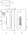
図1は、ソケットコネクタの4面図である。(A)は背面図、(B)は平面図、(C)は正面図、(D)は側面図を、それぞれ示す。図4は、図1(B)における線E−Eによる断面図であり、図4(A)はソケットコネクタとピンコネクタとが嵌合する前でアクチュエータのスライド前の状態、図4(B)はソケットコネクタとピンコネクタとが嵌合した後でアクチュエータのスライド後の状態を、それぞれ示す。
【0021】
ソケットコネクタ1は、ケース(インシュレータ)2と、ケース2を被覆するカバー(インシュレータ)3と、カバー3に保持されるソケットコンタクト4と、ケース2にスライド可能に搭載されるアクチュエータ5と、アクチュエータ5をスライドさせるカム6(上カム6aと下カム6b)と、圧縮コイルばね8等とから構成される。
【0022】
ケース2とカバー3とは、一対のねじ7によって固定される。カバー3に設けられた複数の突出穴3aから、それぞれ各ソケットコンタクト4の先端部分が露呈する。ケース2には、ピンコネクタの複数のピンコンタクトを挿入するための複数の挿入穴2aが、設けられる。
【0023】
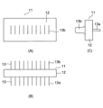
図2は、ソケットコネクタ1と接続するピンコネクタ11の3面図であり、(A)は正面図、(B)は平面図、(C)は側面図を、それぞれ示す。
【0024】
ピンコネクタ11は、インシュレータ12と、インシュレータ12に保持される複数のピンコンタクト13とから構成される。各ピンコンタクト13は、インシュレータ12の一面側から突出してプリント基板に接続するためのピン状の端子13aと、インシュレータ12の他面側から突出してソケットコンタクト4と接触するための薄板状のピン13bとを有する。
【0025】
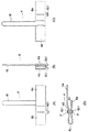
図3は、ソケットコネクタ1のソケットコンタクト4の4面図であり、(A)は正面図、(B)は側面図、(C)は背面図、(D)は下面図を、それぞれ示す。
【0026】
各ソケットコンタクト4は、ケース2への固定部4aと、第1の接点Pを含む略ヘ字形部4bと、略U字形状部4cと、第2の接点Pを含む略へ字形部4dと、アクチュエータ5に押圧される可動部4eと、固定部4aから突出する端子部4fとから連続して一体に構成される。第1の接点Pと第2の接点Pとは、両者の間にギャップを有するように対向して構成される。また、第1の接点Pと第2の接点Pの各外側には、ガイド4b1,4d1が対称形に設けられる。ガイド4b1,4d1は、各ピンコンタクト13のピン13bが各ソケットコンタクト4と干渉することに起因して生じる座屈無しに無挿入力で各接点Pと接触するように、ピン13bを各接点Pのギャップ内に導入する。このようにして、図4(A)において、下カム6bが矢印方向に回転すると、アクチュエータ5は矢印方向に図4(B)の位置までスライドする。このとき、アクチュエータ5がソケットコンタクト4の可動部4eを変位させて、各接点Pは各ピンコンタクト13のピン13bを挟圧するZIF機能を営む(詳細は後述する。)。
【0027】
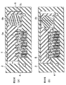
図5は、ソケットコネクタ1とピンコネクタ11とが嵌合する前後の要部の拡大断面図であり、(A)は嵌合前でアクチュエータ5のスライド前の状態(B)は嵌合後でアクチュエータ5のスライド後の状態をそれぞれ示す。
【0028】
図5(A)において、ソケットコンタクト4の大部分はケース2のコンタクト溝2cに収納され、固定部4aの先端及び側面はそれぞれケース2のストッパ2d及び固定壁2eに当接し、可動部4eはアクチュエータ5の駆動溝5aに収納され、ガイド4b1,4d1はケース2のガイド溝2fに収納されている。ここで、各接点Pのギャップgは、ピン13bの厚さtよりも大きく構成される。
【0029】
ピンコネクタ11がソケットコネクタ1と接続するとき、アクチュエータ5が図5(A)の位置から図5(B)の位置までスライドすると、カム機構6の上カム6aと下カム6bとが連動して右回転する(図1(A)と図4(A)参照)。ソケットコンタクト4の可動部4eは、アクチュエータ5の駆動溝5aの斜面の角5bから力f1 を受けるので、ソケットコンタクト4は、弾性変形する。このとき、固定部4aの側面は、ケース2の固定壁2eから抗力を受けるので、各接点Pは、ピンコネクタ11のピン13bの両面を挟圧することによってその両面から力f2 、f3 を受ける。
【0030】
本発明の要点のロック機構について図6と図7を参照して説明する。
【0031】
図6(A),(B)に示されるように、カバー3に設けられた円形のカム挿入用穴3bの上側には、円形の上カム6aが開位置と閉位置との間を90°回転可能に装着されている。上カム6aは、表面にマイナスドライバ挿入用のマイナス溝6a1、周縁の対称位置に一対の被ロックボス6a2、裏面に長方形ボス6a3を、それぞれ有する。
【0032】
上カム6aに対応して、下カム6bがケース2とカバー3に90°回転可能に装着されている。下カム6bは、表面に長方形ボス穴6b1、長方形ボス穴6b1に連続する圧縮コイルばね挿入用の円形穴6b2、裏面に回転中心穴6b3を、それぞれ有する。
【0033】
上カム6aの長方形ボス6a3と下カム6bの円形穴6b2との間には、円形の圧縮コイルばね8が挿入されている。
【0034】
カバー3のカム挿入用穴3bには、上カム6aが上下方向に移動することができるように間隙3b1,3b2が設けられ、また、図7(A)に示されるように、上カム6aの一対の被ロックボス6a2が開位置(嵌合前)で係合する一対のロックボス溝3b3と閉位置(嵌合後)で係合する一対のロックボス溝3b4とが設けられる。一対の被ロックボス6a2は、位相が180°異なり、二対のロックボス溝3b3,3b4は、位相が90°異なる。
【0035】
ケース2には、アクチュエータ5がスライドすることができるようにアクチュエータ挿入用穴2b(図5(B)参照)が設けられる。アクチュエータ5には、下カム6bが回転することができるように下カム挿入用穴5c(図4(A)参照)が設けられる。また、ケース2には、下カム6bの回転中心穴6b3がはまる支持軸2gが設けられる。
【0036】
ロック機構の操作について説明する。まず、図6(A),(B)、図7(B)において、マイナスドライバ(図示せず)を上カム6aのマイナス溝6a1に挿入して、上カム6aをカバー3のカム挿入用穴3b内方に圧縮コイルばね8を圧縮して押し込む。すると、上カム6aは、図6(C)の状態に至り、一対の被ロックボス6a2は、カバー3の一対のロックボス溝3b3からロックを解除される(換言すると、脱出する。)。
【0037】
次に、上カム6aを90°右回転すると、上カム6aは、図6(D),(E)、図7(C)の状態に至る。このとき、上カム6aの長方形ボス6a3と下カム6bの長方形ボス穴6b1とが図7(D)に示されるように、はまっているため、下カム6Dも90°右回転する。したがって、図4(A)に示されるように、下カム6bは、アクチュエータ5を矢印方向にスライドさせ、図4(B)に示される状態に至る。この状態では、下カム6bは、アクチュエータ5に力f4の作用を及ぼし、アクチュエータ5は、各ソケットコンタクト4から力f1 の反作用を受ける。
【0038】
続いて、マイナスドライバを上カム6aのマイナス溝6a1から撤去すると、上カム6aは、圧縮コイルばね8の拡張力によって図6(F)に示される状態に至る。このとき、一対の被ロックボス6a2は、カバー3の一対のロックボス溝3b4内に進入する。すなわち、上カム6aは、回転を制止されてロックされる。
【0039】
なお、本実施の形態例では、ケース2とカバー3とを、別個の部品から構成したが、1個の部品から構成するように設計変更することができる。
【0040】
【発明の効果】
以上の説明から明らかなように、本発明によれば、次の効果が奏される。
【0041】
1.コネクタと相手側コネクタとの接続又は非接続の所要の一方の状態は、衝撃又は振動等が生じても、コネクタのロック機構によって確実に維持される。
【0042】
2.ロック機構の操作は、マイナスドライバ等による第1のカムの押し込みと回転と撤去であるので、簡単容易に行うことができる。
【0043】
3.ロック機構は、第1のカムと第2のカムと弾性部材とから構成されるため、部品点数が少なく、構造が簡素、かつ、コンパクトで、組立分解が簡単容易で、コストが安価である。
【図面の簡単な説明】
【図1】本発明の一実施の形態例のソケットコネクタのロック機構の4面図であり、(A)は背面図、(B)は平面図、(C)は正面図、(D)は側面図を、それぞれ示す。
【図2】同ソケットコネクタと接続するピンコネクタの3面図であり、(A)は正面図、(B)は平面図、(C)は側面図を、それぞれ示す。
【図3】同ソケットコネクタのコンタクトの4面図であり、(A)は正面図、(B)は側面図、(C)は背面図、(D)は下面図を、それぞれ示す。
【図4】図1(B)における線E−Eによる断面図であり、(A)は同ピンコネクタが嵌合前で非接続状態、(B)は同ピンコネクタが嵌合後で接続状態を、それぞれ示す。
【図5】同ソケットコネクタと同ピンコネクタとが嵌合する前後の要部の拡大断面図であり、(A)は嵌合前でアクチュエータのスライド前の状態、(B)は嵌合後でアクチュエータのスライド後の状態を、それぞれ示す。
【図6】同ソケットコネクタのロック機構の諸図であり、(A)は非接続状態(開位置)の平面図、(B)は(A)における線A−Aによる断面図、(C)は(B)において上カムがカバー内に押し込まれた状態の断面図、(D)は接続状態(閉位置)の平面図、(E)は(D)における線B−Bによる断面図、(F)は(E)において上カムが復元した状態の断面図を、それぞれ示す。
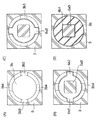
【図7】図6(B)における線C−Cと線D−Dによる各拡大断面図であり、(A)は線C−Cによるもの(ただし、上カムを図示せず)、(B)は線C−Cによる非接続状態、(C)は線C−Cによる接続状態、(D)は線D−Dによるものを、それぞれ示す。
【図8】従来のZIFコネクタの断面図であり、(A)は非接続状態、(B)は接続状態を、それぞれ示す。
【符号の説明】
1 ソケットコネクタ
2 ケース(インシュレータ)
2a 挿入穴
2b アクチュエータ挿入用穴
2c コンタクト溝
2d ストッパ
2e 固定壁
2f ガイド溝
2g 支持軸
3 カバー(インシュレータ)
3a 突出穴
3b カム挿入用穴
3b1 間隙
3b2 間隙
3b3 ロックボス溝
3b4 ロックボス溝
4 ソケットコンタクト
4a 固定部
4b 略へ字形部
4b1 ガイド
4c 略U字形状部
4d 略へ字形部
4d1 ガイド
4e 可動部
4f 端子部
5 アクチュエータ
5a 駆動溝
5b 斜面の角
5c 下カム挿入用穴
6 カム
6a 上カム
6a1 マイナス溝
6a2 被ロックボス
6a3 長方形ボス
6b 下カム
6b1 長方形ボス穴
6b2 円形穴
6b3 回転中心穴
7 ねじ
8 圧縮コイルばね
11 ピンコネクタ
12 インシュレータ
13 ピンコンタクト
13a 端子
13b ピン[0001]
TECHNICAL FIELD OF THE INVENTION
The present invention relates to a connector such as a ZIF (Zero Insertion Force No Insertion Force), and more particularly, to a connector in which connection and disconnection are switched by a slide operation between a connection and a disconnection of a mating connector. And a lock mechanism capable of reliably maintaining the lock mechanism.
[0002]
[Prior art]
A conventional ZIF connector will be described with reference to FIG. 8 (for example, see Patent Document 1). FIG. 8A shows a disconnected state, and FIG. 8B shows a connected state.
[0003]
The ZIF connector includes a
[0004]
The
[0005]
The
[0006]
The
[0007]
The
[0008]
In the state of FIG. 8A, the tip of each
[0009]
8A, when the
[0010]
This type of ZIF connector is also described in other documents (for example, see Patent Document 2).
[0011]
[Patent Document 1]
JP-A-2000-306664 (
[0012]
[Patent Document 2]
JP-A-2000-286025 (
[0013]
[Problems to be solved by the invention]
In the conventional ZIF connector, connection and disconnection of the ZIF connector are switched via an intermediate mechanism by sliding a slider. Therefore, when a shock or vibration or the like occurs in the ZIF connector, the required one state of connection or non-connection of the ZIF connector is not reliably maintained.
[0014]
Therefore, the present invention improves the drawbacks of the conventional ZIF connector, and can reliably maintain one of the required states of connection or non-connection with a mating connector even when shock or vibration occurs. To provide a lock mechanism.
[0015]
[Means for Solving the Problems]
The present invention employs the following means in order to solve the above problems.
[0016]
1. In a connector that switches connection and disconnection with a mating connector by operating a cam, the cam includes a first cam provided with a locked portion whose rotation is locked, and a connection between the two connectors. A second cam provided with a cam portion for switching connection / disconnection, wherein the first cam is slidably and rotatably held by an insulator of the connector, and the second cam Is rotatably held by the insulator, and rotates in conjunction with the rotation of the first cam. The first cam and the second cam are disposed to face each other, and an elastic member , The locked portion of the first cam is locked by the lock portion provided on the insulator, and the first cam is slid toward the second cam. Let me After releasing the click, the the rotation of the first cam, the two connectors of the connection and the locking mechanism of a connector for switching disconnection.
[0017]
2. 2. The connector locking mechanism according to
[0018]
3. The connector lock according to
[0019]
BEST MODE FOR CARRYING OUT THE INVENTION
A lock mechanism of a ZIF connector according to an embodiment of the present invention will be described with reference to FIGS.
[0020]
FIG. 1 is a four side view of the socket connector. (A) is a rear view, (B) is a plan view, (C) is a front view, and (D) is a side view. FIG. 4 is a sectional view taken along line EE in FIG. 1 (B), and FIG. 4 (A) shows a state before the socket connector and the pin connector are fitted and before the actuator slides, and FIG. 4 (B). Shows the state of the actuator after sliding after the socket connector and the pin connector have been fitted, respectively.
[0021]
The
[0022]
The
[0023]
2A and 2B are three views of the
[0024]
The
[0025]
3A and 3B are four views of the
[0026]
Each
[0027]
5A and 5B are enlarged cross-sectional views of main parts before and after the
[0028]
In FIG. 5A, most of the
[0029]
When the
[0030]
The lock mechanism of the present invention will be described with reference to FIGS.
[0031]
As shown in FIGS. 6A and 6B, above the circular
[0032]
A
[0033]
A circular
[0034]
Gaps 3b1 and 3b2 are provided in the
[0035]
The
[0036]
The operation of the lock mechanism will be described. First, in FIGS. 6A, 6B, and 7B, a flathead screwdriver (not shown) is inserted into the flat groove 6a1 of the
[0037]
Next, when the
[0038]
Subsequently, when the flathead screwdriver is removed from the flat groove 6a1 of the
[0039]
In the present embodiment, the
[0040]
【The invention's effect】
As is clear from the above description, the present invention has the following effects.
[0041]
1. The required one state of connection or non-connection between the connector and the mating connector is reliably maintained by the locking mechanism of the connector even when shock or vibration occurs.
[0042]
2. The operation of the lock mechanism can be easily and easily performed because the first cam is pushed, rotated, and removed by a flathead screwdriver or the like.
[0043]
3. Since the lock mechanism includes the first cam, the second cam, and the elastic member, the number of parts is small, the structure is simple and compact, the assembly and disassembly are easy, and the cost is low.
[Brief description of the drawings]
1A and 1B are four views of a locking mechanism of a socket connector according to an embodiment of the present invention, wherein FIG. 1A is a rear view, FIG. 1B is a plan view, FIG. 1C is a front view, and FIG. Side views are shown respectively.
FIGS. 2A and 2B are three views showing a pin connector connected to the socket connector, wherein FIG. 2A is a front view, FIG. 2B is a plan view, and FIG.
3A and 3B are four side views of the contact of the socket connector, wherein FIG. 3A is a front view, FIG. 3B is a side view, FIG. 3C is a rear view, and FIG. 3D is a bottom view.
4A is a cross-sectional view taken along line EE in FIG. 1B, wherein FIG. 4A is a non-connected state before the same pin connector is fitted, and FIG. 4B is a connected state after the same pin connector is fitted; Are respectively shown.
FIG. 5 is an enlarged cross-sectional view of a main part before and after the socket connector and the pin connector are fitted, wherein (A) is a state before the fitting and before the actuator slides, and (B) is a state after the fitting. The state after sliding of the actuator is shown, respectively.
6A and 6B are various views of a locking mechanism of the socket connector, wherein FIG. 6A is a plan view in a disconnected state (open position), FIG. 6B is a cross-sectional view taken along line AA in FIG. (D) is a cross-sectional view in a state where the upper cam is pushed into the cover in (B), (D) is a plan view in a connected state (closed position), (E) is a cross-sectional view along line BB in (D), (F) is a sectional view of the state where the upper cam is restored in (E).
FIGS. 7A and 7B are enlarged sectional views taken along lines CC and DD in FIG. 6B. FIG. 7A is a sectional view taken along line CC (however, the upper cam is not shown); ) Shows a non-connection state by line CC, (C) shows a connection state by line CC, and (D) shows a state by line DD.
8A and 8B are cross-sectional views of a conventional ZIF connector, wherein FIG. 8A shows a non-connected state, and FIG. 8B shows a connected state.
[Explanation of symbols]
1
Claims (3)
前記カムは、その回転をロックされる被ロック部が設けられた第1のカムと、前記両コネクタの接続と非接続の切替を行うカム部が設けられた第2のカムとから構成され、
前記第1のカムは、スライド可能に、かつ、回転可能に前記コネクタのインシュレータに保持され、前記第2のカムは、回転可能に前記インシュレータに保持され、かつ、前記第1のカムの回転に連動して回転し、
前記第1のカムと前記第2のカムとは、対向して配設され、弾性部材で離間する方向に常時付勢されることによって、前記第1のカムの被ロック部が前記インシュレータに設けられたロック部にロックされ、
前記第1のカムを前記第2のカムに向かってスライドさせてロックを解除した後、前記第1のカムの回転によって、前記両コネクタの接続と非接続の切替を行うことを特徴とするコネクタのロック機構。In the connector that switches between connection and disconnection with the mating connector by operating the cam,
The cam includes a first cam provided with a locked portion whose rotation is locked, and a second cam provided with a cam portion for switching between connection and disconnection of the two connectors,
The first cam is slidably and rotatably held by the insulator of the connector, and the second cam is rotatably held by the insulator and rotates the first cam. Rotate in conjunction with
The first cam and the second cam are disposed to face each other, and are constantly urged in a direction in which they are separated by an elastic member, so that a locked portion of the first cam is provided on the insulator. Locked by the locked part,
A connector, characterized in that, after the first cam is slid toward the second cam to release the lock, connection and disconnection of the two connectors are switched by rotation of the first cam. Lock mechanism.
Priority Applications (5)
| Application Number | Priority Date | Filing Date | Title |
|---|---|---|---|
| JP2003069499A JP3907601B2 (en) | 2003-03-14 | 2003-03-14 | Connector locking mechanism |
| PCT/JP2004/003277 WO2004082081A1 (en) | 2003-03-14 | 2004-03-12 | Connector allowing locking of connected state or non-connected state |
| DE112004000436T DE112004000436T5 (en) | 2003-03-14 | 2004-03-12 | Locking a connected state or a non-connected state capable of plug |
| CA002519276A CA2519276C (en) | 2003-03-14 | 2004-03-12 | Connector capable of locking connected state or non-connected state |
| US10/549,092 US7214082B2 (en) | 2003-03-14 | 2004-03-12 | Connector allowing locking of connected state or non-connected state |
Applications Claiming Priority (1)
| Application Number | Priority Date | Filing Date | Title |
|---|---|---|---|
| JP2003069499A JP3907601B2 (en) | 2003-03-14 | 2003-03-14 | Connector locking mechanism |
Publications (2)
| Publication Number | Publication Date |
|---|---|
| JP2004281174A true JP2004281174A (en) | 2004-10-07 |
| JP3907601B2 JP3907601B2 (en) | 2007-04-18 |
Family
ID=32984618
Family Applications (1)
| Application Number | Title | Priority Date | Filing Date |
|---|---|---|---|
| JP2003069499A Expired - Fee Related JP3907601B2 (en) | 2003-03-14 | 2003-03-14 | Connector locking mechanism |
Country Status (5)
| Country | Link |
|---|---|
| US (1) | US7214082B2 (en) |
| JP (1) | JP3907601B2 (en) |
| CA (1) | CA2519276C (en) |
| DE (1) | DE112004000436T5 (en) |
| WO (1) | WO2004082081A1 (en) |
Families Citing this family (2)
| Publication number | Priority date | Publication date | Assignee | Title |
|---|---|---|---|---|
| RU2343607C1 (en) * | 2007-08-17 | 2009-01-10 | Юрий Игоревич Донецкий | Plug and socket joint |
| US12355167B2 (en) * | 2022-07-28 | 2025-07-08 | Micron Technology, Inc. | Connection designs for memory systems |
Family Cites Families (16)
| Publication number | Priority date | Publication date | Assignee | Title |
|---|---|---|---|---|
| JPH0429512Y2 (en) * | 1986-12-10 | 1992-07-16 | ||
| US4836798A (en) * | 1987-12-21 | 1989-06-06 | Wells Electronics, Inc. | Zero insertion socket with normally closed contacts |
| JPH0429512A (en) | 1990-05-25 | 1992-01-31 | Mitsubishi Electric Corp | Interlock unit for insertion type circuit breaker provided with electrical operating unit |
| JP3302720B2 (en) * | 1992-06-09 | 2002-07-15 | ミネソタ マイニング アンド マニュファクチャリング カンパニー | IC socket |
| JP3050275B2 (en) * | 1994-11-29 | 2000-06-12 | 矢崎総業株式会社 | Lever mating connector |
| US5508628A (en) * | 1995-02-01 | 1996-04-16 | Pfaff; Wayne K. | Automated closure test socket |
| US5704800A (en) * | 1995-05-31 | 1998-01-06 | Japan Aviation Electronics Industry, Limited | Electrical connector for connection to LSI package having preloaded and cantilevered plate type contact with L-shape slits for providing two contact points |
| JP3073936B2 (en) * | 1996-12-26 | 2000-08-07 | 日本航空電子工業株式会社 | connector |
| JPH10288345A (en) * | 1997-04-16 | 1998-10-27 | Matsushita Electric Ind Co Ltd | Operation knob device |
| JP3338892B2 (en) * | 1999-03-31 | 2002-10-28 | 日本航空電子工業株式会社 | Electrical connector |
| JP3355480B2 (en) * | 1999-04-22 | 2002-12-09 | 日本航空電子工業株式会社 | ZIF connector |
| TW481378U (en) * | 2001-04-24 | 2002-03-21 | Hon Hai Prec Ind Co Ltd | Zero insertion force connector |
| JP4721582B2 (en) * | 2001-09-14 | 2011-07-13 | 株式会社センサータ・テクノロジーズジャパン | socket |
| GB2391723B (en) * | 2002-07-15 | 2004-11-17 | Japan Aviation Electron | Zif connector having a contact of unique shape |
| JP3788957B2 (en) * | 2002-07-15 | 2006-06-21 | 日本航空電子工業株式会社 | ZIF connector |
| US6746262B2 (en) * | 2002-09-09 | 2004-06-08 | Hon Hai Precision Ind. Co., Ltd. | Socket connector with actuator mechanism mating means |
-
2003
- 2003-03-14 JP JP2003069499A patent/JP3907601B2/en not_active Expired - Fee Related
-
2004
- 2004-03-12 CA CA002519276A patent/CA2519276C/en not_active Expired - Fee Related
- 2004-03-12 DE DE112004000436T patent/DE112004000436T5/en not_active Withdrawn
- 2004-03-12 WO PCT/JP2004/003277 patent/WO2004082081A1/en not_active Ceased
- 2004-03-12 US US10/549,092 patent/US7214082B2/en not_active Expired - Fee Related
Also Published As
| Publication number | Publication date |
|---|---|
| US7214082B2 (en) | 2007-05-08 |
| DE112004000436T5 (en) | 2006-02-16 |
| CA2519276C (en) | 2008-09-09 |
| JP3907601B2 (en) | 2007-04-18 |
| CA2519276A1 (en) | 2004-09-23 |
| US20060178032A1 (en) | 2006-08-10 |
| WO2004082081A1 (en) | 2004-09-23 |
| WO2004082081A9 (en) | 2005-05-26 |
Similar Documents
| Publication | Publication Date | Title |
|---|---|---|
| CN100472887C (en) | Connector | |
| US6979216B2 (en) | Electrical connector having a mechanism for supplementing spring characteristics of a contact | |
| US7140896B2 (en) | Connector | |
| TW498573B (en) | Connector excellent in reliability of contact | |
| KR101046856B1 (en) | Card connector | |
| JP3472686B2 (en) | Slide mating type connector | |
| US7407398B2 (en) | Lever type electrical connector | |
| JPH08115776A (en) | Right angle connector | |
| JP4798277B2 (en) | connector | |
| JP2822852B2 (en) | Card edge connector | |
| JP2010027520A (en) | Connector device | |
| JPH10334993A (en) | Connector device | |
| US7033208B1 (en) | Flexible printed circuit connector | |
| JP2003077585A (en) | Cable connector | |
| JP3146200U (en) | Electrical connector | |
| JP3907601B2 (en) | Connector locking mechanism | |
| CA2435135C (en) | Zif connector having a contact of unique shape | |
| US20040018768A1 (en) | Socket connector with resiliently engaged actuator mechanism | |
| JP2001143827A (en) | Connector for plate | |
| JP3812943B2 (en) | ZIF connector with locking mechanism | |
| JP4089578B2 (en) | Wiring equipment | |
| JP3355480B2 (en) | ZIF connector | |
| JP3788957B2 (en) | ZIF connector | |
| JP2696308B2 (en) | No insertion force connector | |
| JP3557597B2 (en) | ZIF connector |
Legal Events
| Date | Code | Title | Description |
|---|---|---|---|
| TRDD | Decision of grant or rejection written | ||
| A01 | Written decision to grant a patent or to grant a registration (utility model) |
Free format text: JAPANESE INTERMEDIATE CODE: A01 Effective date: 20061227 |
|
| A61 | First payment of annual fees (during grant procedure) |
Free format text: JAPANESE INTERMEDIATE CODE: A61 Effective date: 20070116 |
|
| R150 | Certificate of patent or registration of utility model |
Free format text: JAPANESE INTERMEDIATE CODE: R150 |
|
| FPAY | Renewal fee payment (event date is renewal date of database) |
Free format text: PAYMENT UNTIL: 20100126 Year of fee payment: 3 |
|
| FPAY | Renewal fee payment (event date is renewal date of database) |
Free format text: PAYMENT UNTIL: 20110126 Year of fee payment: 4 |
|
| FPAY | Renewal fee payment (event date is renewal date of database) |
Free format text: PAYMENT UNTIL: 20110126 Year of fee payment: 4 |
|
| FPAY | Renewal fee payment (event date is renewal date of database) |
Free format text: PAYMENT UNTIL: 20120126 Year of fee payment: 5 |
|
| FPAY | Renewal fee payment (event date is renewal date of database) |
Free format text: PAYMENT UNTIL: 20130126 Year of fee payment: 6 |
|
| FPAY | Renewal fee payment (event date is renewal date of database) |
Free format text: PAYMENT UNTIL: 20140126 Year of fee payment: 7 |
|
| R250 | Receipt of annual fees |
Free format text: JAPANESE INTERMEDIATE CODE: R250 |
|
| R250 | Receipt of annual fees |
Free format text: JAPANESE INTERMEDIATE CODE: R250 |
|
| LAPS | Cancellation because of no payment of annual fees |