JP2004285657A - Grille body, and grille for window using the same - Google Patents
Grille body, and grille for window using the same Download PDFInfo
- Publication number
- JP2004285657A JP2004285657A JP2003077818A JP2003077818A JP2004285657A JP 2004285657 A JP2004285657 A JP 2004285657A JP 2003077818 A JP2003077818 A JP 2003077818A JP 2003077818 A JP2003077818 A JP 2003077818A JP 2004285657 A JP2004285657 A JP 2004285657A
- Authority
- JP
- Japan
- Prior art keywords
- surface portion
- lattice
- crosspiece
- vertical bar
- vertical
- Prior art date
- Legal status (The legal status is an assumption and is not a legal conclusion. Google has not performed a legal analysis and makes no representation as to the accuracy of the status listed.)
- Pending
Links
- 239000000463 material Substances 0.000 claims abstract description 46
- 238000003780 insertion Methods 0.000 claims abstract description 29
- 230000037431 insertion Effects 0.000 claims abstract description 29
- 238000003466 welding Methods 0.000 description 15
- 230000000694 effects Effects 0.000 description 11
- 238000013461 design Methods 0.000 description 7
- 239000011324 bead Substances 0.000 description 5
- 238000000034 method Methods 0.000 description 5
- 238000005452 bending Methods 0.000 description 4
- XLYOFNOQVPJJNP-UHFFFAOYSA-N water Substances O XLYOFNOQVPJJNP-UHFFFAOYSA-N 0.000 description 3
- 229910052782 aluminium Inorganic materials 0.000 description 2
- XAGFODPZIPBFFR-UHFFFAOYSA-N aluminium Chemical compound [Al] XAGFODPZIPBFFR-UHFFFAOYSA-N 0.000 description 2
- 230000007797 corrosion Effects 0.000 description 2
- 238000005260 corrosion Methods 0.000 description 2
- 230000008014 freezing Effects 0.000 description 2
- 238000007710 freezing Methods 0.000 description 2
- 230000001771 impaired effect Effects 0.000 description 2
- 238000012545 processing Methods 0.000 description 2
- 229910000831 Steel Inorganic materials 0.000 description 1
- 230000001154 acute effect Effects 0.000 description 1
- 238000013459 approach Methods 0.000 description 1
- 238000005219 brazing Methods 0.000 description 1
- 230000002349 favourable effect Effects 0.000 description 1
- 230000008595 infiltration Effects 0.000 description 1
- 238000001764 infiltration Methods 0.000 description 1
- 239000011810 insulating material Substances 0.000 description 1
- 238000004519 manufacturing process Methods 0.000 description 1
- 229910052751 metal Inorganic materials 0.000 description 1
- 239000002184 metal Substances 0.000 description 1
- 238000012986 modification Methods 0.000 description 1
- 230000004048 modification Effects 0.000 description 1
- 238000005192 partition Methods 0.000 description 1
- 230000002265 prevention Effects 0.000 description 1
- 238000004080 punching Methods 0.000 description 1
- 229920005989 resin Polymers 0.000 description 1
- 239000011347 resin Substances 0.000 description 1
- 238000009751 slip forming Methods 0.000 description 1
- 125000006850 spacer group Chemical group 0.000 description 1
- 239000010959 steel Substances 0.000 description 1
- 229920003002 synthetic resin Polymers 0.000 description 1
- 239000000057 synthetic resin Substances 0.000 description 1
Images


Landscapes
- Grates (AREA)
Abstract
Description
【0001】
【発明の属する技術分野】
本発明は、格子体、およびこの格子体を用いた面格子に関する。
【0002】
【背景技術】
従来より、建物の外壁開口部等に取り付けられる面格子や、階段、通路、バルコニー等に設けられる手摺り、柵(フェンス)、門扉等に用いられる格子体が知られている。このような格子体として、躯体等に固定される枠体と、この枠体の内側に取り付けられた複数の縦桟とから構成された格子体が提案されている(例えば、特許文献1参照)。特許文献1に記載された格子体(格子材)では、上側の枠材が下方に開口した断面略C字形に形成され、この枠材の開口部分に縦桟を挿入するとともに、枠材の開口部分を室内外両側から縦桟に向かって加圧し、互いを溶接、固定して、一体に形成されている。
【0003】
【特許文献1】
実開昭52−3257号公報
【0004】
【発明が解決しようとする課題】
しかしながら、特許文献1に記載の格子体では、枠材のC字形の開口部分に縦桟を挿入しただけでは、溶接して固定する際に互いの部材が安定しないので、枠材および縦桟を位置決めした状態で仮固定しておく必要があり、組立作業の作業効率が低いという問題がある。
また、枠材および縦桟の溶接固定部分が枠材の室内外両側に露出しているため、格子体の外観の意匠性が損なわれるという問題もある。
【0005】
本発明の目的は、組立作業の作業効率向上を図ることができ、かつ、外観を良好にできる格子体、およびこの格子体を用いた面格子を提供することにある。
【0006】
【課題を解決するための手段】
本発明の格子体は、所定間隔離れて設けられた一対の長尺な支持材と、これらの支持材間に架設された複数の桟材とを備えた格子体であって、前記各支持材は、前記複数の桟材の端部が挿通される複数の挿通孔を有した交差面部と、この交差面部の長手方向に沿った両側端縁から、他の支持材から離れる方向にそれぞれ延出された2つの側面部とを備え、前記2つの側面部のうち、一方の側面部に前記桟材の側面が当接して固定されていることを特徴とする。
【0007】
このような本発明によれば、支持材の交差面部に設けた挿通孔に桟材を挿通することで、桟材と交差した支持材の長手方向および直交方向について、桟材を位置決め可能であるとともに、支持材の一方の側面部を桟材の側面に当接することで、挿通孔および側面部の少なくとも2箇所で桟材と当接するため、支持材に沿った軸線を中心とした回転方向についても、桟材を位置決め可能である。従って、格子体の組み立てに際して、支持材および桟材が安定して位置決めされた状態で、溶接等による固定作業を実施することができ、組立作業の作業効率向上を図ることができる。
また、支持材の一方側に形成された側面部を、桟材の側面に固定することで、例えば、溶接により両部材を固定した場合には、固定部分である溶接ビードが他方側の側面には表れず、他方側をより人目に付く側に向けて設置すれば、外観を良好にすることができる。
【0008】
さらに、挿通孔が設けられた交差面部の両側端縁に側面部が連続して形成されているので、挿通孔周辺の部材強度を確保できるため、室内に侵入を謀ろうとする者が挿通孔部分から支持材を破壊しづらくし、防犯性を高めることができる。また、従来の格子体においては、下側の枠材と縦桟とが固定されておらず、上下の枠材を連結する縦枠材等が必要であるが、本発明の格子体では、2本の支持材のいずれもが、桟材に固定されるため、これら2本の支持材を連結する枠材を不要にでき、部品点数を削減することができる。さらに、本発明の格子体では、2本の支持材を同一部品から構成できるため、部品の共通化を図ることができる。
【0009】
この際、本発明の格子体では、前記一方の側面部は、前記交差面部と略平行で、かつ前記桟材の側面に向って折り曲げた折曲部を有し、この折曲部が前記桟材の側面に当接していることを特徴とする。
このような構成では、支持材の一方側に形成された側面部を桟材に向かって折り曲げ、この折曲部を桟材の側面に当接、固定したので、2本の支持材の間隔内側であれば格子体から多少離れた位置からであっても、折曲部に隠れて固定部分を見えなくできるので、さらに外観を良好にすることができる。
【0010】
さらに、本発明の格子体では、前記支持材は、前記2つの側面部のうちの他方の側面部に連続して形成され、かつ前記交差面部と対向配置される外面部を備え、この外面部に前記桟材の先端が当接していることを特徴とする。
このような構成では、支持材の他方側に形成された側面部に連続して、桟材の先端が当接する外面部を形成することで、桟材の先端を支持材で覆うことができ、例えば、桟材を中空パイプ状の部材で構成した場合などに、桟材の内部への雨水等の浸入を防止できる。また、格子体の組み立てに際して、支持材の外面部に桟材の先端を当接することで、桟材に沿った方向の位置決めが可能になり、組立作業の作業効率をさらに向上させることができる。
【0011】
また、本発明の格子体では、前記2本の支持材が互いに上下に対向し、かつ、略水平に配置されることを特徴とする。
このような構成では、2本の支持材を互いに上下に、かつ水平にして設置することで、桟材が上下方向に延びる一般的な面格子、手摺り、柵、門扉等を構成できるとともに、支持材が上下対称に配置されるので、外観のデザインを統一し、意匠性を向上させることができる。
また、従来の格子体において、上下の枠材を共通化して、デザインを統一しようとすれば、上側の枠材を上下反転させて下側に配置することも可能であるが、断面略C字形の枠材を上方に開口させて配置すると、枠材内部に浸入した雨水等が排出されづらく、この水が枠材を腐食させたり、冬季に凍結することで枠材の破損の原因になるなどの不都合を生じる。
本発明の格子体においては、下側の支持材の側面部は、交差面部から下方に向かって延出することになるため、下側の支持材に雨水等が浸入しにくく、また、雨水が浸入した場合でも、直ちに排出されるようになっている。また、上側の支持材の側面部は交差面部から上方に向かって延出することになるが、交差面部には、挿通孔が設けられているために、支持材に浸入した雨水等は挿通孔から排出されるようになっている。従って、本発明の格子体では、支持材内部に水が溜まりにくいので、腐食や凍結による破損を防止することができ、耐久性を確保することができる。
【0012】
一方、本発明の面格子では、前記したいずれかの格子体と、前記格子体を構成する2本の支持材に取り付けた壁固定用のブラケットとを備えたことを特徴とする。
このような本発明によれば、当該面格子において前述した各効果と同様の効果を奏することができる。また、壁固定用のブラケットを介して支持材を壁に固定することができるので、支持材同士を連結する枠材等が不要で、部品点数を削減することができる。
【0013】
【発明の実施の形態】
〔第1実施形態〕
以下、本発明の第1実施形態を図面に基づいて説明する。
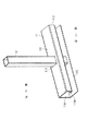
図1ないし図4に、本実施形態に係る格子体を用いた面格子10を示す。図1は、面格子10が設けられた開口部を示す横断面図である。図2は、面格子10の取付部分を拡大して示す分解斜視図である。図3および図4は、それぞれ面格子10の要部を示す斜視図および縦断面図である。
【0014】
面格子10は、図1に示すように、例えば、住宅等の外壁1に設けられた開口部2における防犯性を確保するために、開口部2の室外側に取り付けられている。外壁1は、躯体としての柱3の室内外側にそれぞれ固定された内装材4や、外装材5から構成されている。また、図示を省略するが、内装材4および外装材5の間には、適宜な断熱材や防水材等が介装されている。開口部2は、見付け形状が矩形状の窓であって、室内側に窓台6や額縁7が設けられ、これらの窓台6、額縁7の室外側に窓枠8が固定されている。窓枠8は、上枠、下枠、および左右の縦枠を四周枠組みして形成されており、窓台6、額縁7、および柱3にビス止め等で固定されている。そして、窓枠8には、図示しない障子が取り付けられており、この障子が引き違い形式のものであれば、開口部2は、引き違い窓として開閉可能に構成されることとなる。
【0015】
面格子10は、開口部2の上下辺に沿って略水平に延びる2本の支持材としての横材11と、これらの横材11間に渡って上下に延び、横材11の長手方向に沿って複数並べられた桟材としての縦桟12と、横材11の両端に固定された壁固定用のブラケット13とを備えて構成されている。これらの横材11、縦桟12、およびブラケット13は、SUS製の板材から曲げ加工により形成されている。そして、外装材5を貫通して柱3にねじ止めされるビス14でブラケット13を固定することで、面格子10は、外壁1に強固に固定されている。
【0016】
横材11は、図2ないし図4に示すように、長尺棒状で断面略e字形に形成されており、上下の横材11は、互いに上下対称形状となるように配置されている。上下の横材11の対向面、すなわち、上側の横材11における下面、および下側の横材11における上面は、それぞれ縦桟12と略直交する交差面部111になっている。この交差面部111には、複数の縦桟12に対応して、これらの縦桟12が挿通される挿通孔112が、打抜き加工により穿設されている。これらの挿通孔112は、断面略角形筒状の縦桟12をがたつきなく挿通可能な大きさの角穴となっている。そして、挿通孔112には、面格子10の内側から外側、すなわち、上側の横材11における下方から上方、および下側の横材11における上方から下方に向かって、縦桟12が挿通されている。
【0017】
横材11の一方側である室内側には、交差面部111の室内側端縁に連続し、縦桟12の先端が位置する側、すなわち、上側の横材11における上方、および下側の横材11における下方に向かって延出する、一方側の側面部としての第1側面部113が形成されている。この第1側面部113は、交差面部111と略直交して、縦桟12と略平行に延びており、第1側面部113の延出方向先端側で、当該横材11の高さ方向略中間位置には、交差面部111と略平行に、縦桟12に向かって折り曲げられた折曲部113Aが形成されている。そして、この折曲部113Aの先端縁は、縦桟12の側面に当接するとともに、交差面部111の反対側において折曲部113Aと縦桟12の側面とが溶接によりに固定されている。すなわち、上側の横材11における折曲部113Aの上側と、下側の横材11における折曲部113Aの下側とが、縦桟12の側面に溶接、固定されている。
【0018】
横材11の他方側である室外側には、交差面部111の室外側端縁に連続し、縦桟12の先端が位置する側に向かって延出する、他方側の側面部としての第2側面部114が形成されている。この第2側面部114は、交差面部111と略直交して、縦桟12と略平行に延びており、当該横材11における室外側の側面が第2側面部114で形成されている。第2側面部114の先端、すなわち、上側の横材11における上端、および下側の横材11における下端は、それぞれ室内側に向かって折り曲げられ、交差面部111と略平行に延びる外面部115が形成されている。そして、この外面部115の内側には、縦桟12の先端が当接している、すなわち、上側の横材11における外面部115により縦桟12の上端が覆われ、下側の横材11における外面部115により縦桟12の下端が覆われている。
【0019】
ブラケット13は、図2に示すように、室内外方向に延びる取付部131と、外壁1の壁面に沿った固定部132とを備え、全体略L字形に形成されている。取付部131は、断面略C字形のチャンネル材状に形成され、かつ先端部が横材11に向かって折り曲げられており、横材11の交差面部111、第2側面部114、および外面部115の三方を囲んで、横材11の端部を嵌合可能に形成されている。そして、取付部131に横材11の端部を嵌合した状態で、これらを互いに溶接することで、横材11にブラケット13が固定されている。ブラケット13の固定部132には、2箇所のビス孔が設けられ、これらのビス孔を通して2本のビス14により、外壁1にビス止め固定されるようになっている。
【0020】
ビス14は、頭部に設けられた締め付け用の穴が角穴形状を有したタイプのもので、例えば、コードレックス(商品名)ビスが採用されている。このようなタイプのビス14では、四角柱状の先端形状を有する専用工具(ビット)を用いて締め付け、および取り外し作業が実施され、通常のプラスやマイナスのスクリュードライバでは、取り外せないようになっている。また、ビス14を外壁1に締め付け固定した後、頭部の締め付け用角穴には、ロウが埋められ、さらに取り外すことが困難になっている。ビス14を取り外す際には、バーナー等でビス14の頭部を加熱し、ロウを溶かした後に、専用工具を用いて取り外し作業を実施することとなる。
なお、ビス14は、締め付け用の穴が角穴形状のものに限らず、締め付け用の穴がワンウェイ、すなわち、締め付け方向にビスを回転可能で、逆方向には回転不能な形状の締め付け用穴を有したタイプのビスを用いてもよい。また、ビス14の頭部の締め付け用角穴を埋める材料としては、ロウに限らず、溶融可能な材料であればよく、例えば樹脂や金属等であってもよい。
【0021】
次に、以上の構成を備える面格子10の組み立て手順について説明する。
先ず、適宜な組み立て台の上に複数の縦桟12を横にして所定ピッチで並べ、これらの縦桟12の両端を挿通孔112に挿通して、外面部115の内側が縦桟12の先端に当接するように横材11をセットする。この際、縦桟12は、その室外側となる側が下向きになるように並べられており、横材11は、第1側面部113を上に向けて、挿通孔112の室内側縁と折曲部113Aの端縁とが縦桟12の側面に当接した状態でセットされている。これに続いて、横材11の折曲部113Aと縦桟12の側面との交差部分を溶接により固定し、この溶接固定の作業を複数の縦桟12について順次繰り返し実施する。このようにして、2本の横材11と複数の縦桟12とを固定した後に、横材11の両端部にブラケット13をセットし、これらを溶接により固定する。以上のようにして組み立てられた面格子10を住宅等まで運搬し、外壁1の開口部2室外側にセットして、ビス14を締め付けることで、外壁1に固定する。
【0022】
以上のように外壁1に取り付けられた面格子10では、室外側からの外観において、横材11の第2側面部114、交差面部111、および外面部115が見えるが、第1側面部113や縦桟12との固定部分である溶接ビードWは、見えないようになっている。従って、横材11は、あたかも、角柱状の部材であるかのように見え、この横材11に縦桟12が貫入して一体的に形成されたような外観を構成できるようになっている。また、面格子10の室内側からの外観、すなわち、開口部2を通して室内から室外方向を見た場合には、図3に示すように、横材11の交差面部111、および第1側面部113が見えるものの、折曲部113Aや、縦桟12との固定部分である溶接ビードWは、見えないようになっている。
【0023】
このような本実施形態によれば、次のような効果がある。
(1) 横材11の交差面部111に設けた挿通孔112に縦桟12を挿通することで、縦桟12と交差した横材11の長手方向および直交方向について、縦桟12を位置決め可能であるとともに、横材11の第1側面部113の折曲部113Aを縦桟12の側面に当接することで、挿通孔112および折曲部113Aの2箇所で縦桟12と当接するため、横材11に沿った軸線を中心とした回転方向についても、縦桟12を位置決め可能である。従って、面格子10の組み立てに際して、横材11および縦桟12が安定して位置決めされた状態で、溶接による固定作業を実施することができ、組立作業の作業効率向上を図ることができる。
【0024】
(2) また、横材11の室内側に形成された第1側面部113の折曲部113Aを、縦桟12の側面に固定することで、これらの固定部分である溶接ビードWが室外側には表れず、室外側からの外観を良好にすることができる。
【0025】
(3) さらに、第1側面部113の折曲部113Aと縦桟12の側面とを溶接、固定することで、固定部分である溶接ビードWが、開口部2を通して室内側から見えず、室内側からの外観も良好にすることができる。
【0026】
(4) また、横材11において、挿通孔112が設けられた交差面部111の長手方向に沿った両側の端縁に第1、第2側面部113,114が連続して形成されているので、挿通孔112周辺の部材強度を確保できるため、室内に侵入を謀ろうとする者が挿通孔112部分から横材11を破壊しづらくし、防犯性を高めることができる。
【0027】
(5) また、横材11の第2側面部114に連続して、室内側に折り曲げられ、縦桟12の先端が当接する外面部115を形成することで、縦桟12の先端を横材11で覆うことができ、縦桟12の内部への雨水等の浸入を防止できる。さらに、面格子10の組み立てに際して、横材11の外面部115に縦桟12の先端を当接することで、縦桟12に沿った方向の位置決めが可能になり、組立作業の作業効率をさらに向上させることができる。
【0028】
(6) さらに、面格子10下側の横材11の第1、第2側面部113,114は、交差面部111から下方に向かって延出ので、下側の横材11に雨水等が浸入しにくく、また、雨水が浸入した場合でも、直ちに排出されるようになっている。また、上側の横材11の第1、第2側面部113,114は交差面部111から上方に向かって延出することになるが、交差面部111には、挿通孔112が設けられているために、横材11に浸入した雨水等は挿通孔112から排出されるようになっている。従って、横材11内部に水が溜まりにくいので、腐食や凍結による破損を防止することができ、耐久性を確保することができる。
【0029】
(7) また、上下の横材11のいずれもが、縦桟12に固定されるとともに、壁固定用のブラケット13が横材11の両端部に取り付けられているので、これらの横材11同士を連結する枠材等を不要にできるとともに、ブラケット13を介して外壁1に固定することができ、部品点数を削減することができる。さらに、2本の横材11を同一部品から構成できるため、部品の共通化を図ることができるとともに、横材11を上下対称に配置したので、外観のデザインを統一し、意匠性を向上させることができる。
【0030】
〔第2実施形態〕
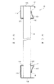
次に、本発明の第2実施形態を図5に基づいて説明する。
図5は、第2実施形態の面格子10の要部を示す縦断面図である。本実施形態の面格子10では、前述の第1実施形態と比較して、横材11における第1側面部113の形態が相違し、その他の構成は同様である。以下、相違点について詳しく説明する。
【0031】
図5に示した本実施形態の面格子10では、横材11の交差面部111から延出する第1側面部113の延出方向が第1実施形態と異なっている。すなわち、第1側面部113は、交差面部111に対して鋭角に折り曲げられ、縦桟12の側面に近づく傾斜を有して延出している。そして、第1側面部113には、第1実施形態のような折曲部が形成されておらず、その先端縁が縦桟12の側面に当接し、これら第1側面部113の先端縁と縦桟12の側面とが溶接により固定されている。
このような構成の面格子10の組み立て手順は、第1実施形態と略同様であり、挿通孔112および第1側面部113の先端縁の2箇所と、外面部115の内側で縦桟12に対する位置決めがなされるようになっている。
【0032】
このような本実施形態によれば、前述の(1)、(2)、(4)〜(7)の効果と合わせて次のような効果がある。
(8) 横材11を折り曲げ加工によって形成する際に、折り曲げ回数を少なくできるので、加工手間を軽減し、加工性を向上させることができる。
【0033】
〔第3実施形態〕
次に、本発明の第3実施形態を図6に基づいて説明する。
図6は、第3実施形態の面格子10の要部を示す縦断面図である。本実施形態の面格子10では、前述の第1実施形態と比較して、横材11における第1側面部113の形態が相違し、その他の構成は同様である。以下、相違点について詳しく説明する。
【0034】
図6に示した本実施形態の面格子10では、横材11の第1側面部113の先端側が折り曲げられる形態が第1実施形態と異なっている。すなわち、第1側面部113は、交差面部111から縦桟12と略平行に延出し、一旦、縦桟12側に折れ曲がって縦桟12の側面に当接するとともに、縦桟12の側面に沿って折れ曲がり、さらに縦桟12の側面に略直交して離れる方向に延びた凹状部113Bを有している。そして、この凹状部113Bの一部、すなわち、上側の横材11におけ凹状部113Bの上側と、下側の横材11における凹状部113Bの下側とが、縦桟12の側面に溶接、固定されている。
このような構成の面格子10の組み立て手順は、第1実施形態と略同様であり、挿通孔112および凹状部113Bの当接面の2箇所で縦桟12に対する位置決めがなされるようになっている。
なお、本実施形態では、第1側面部113と縦桟12の側面とが、溶接に限らず、凹状部113B側から縦桟12の側面まで貫通するビス止めにより固定されてもよい。
【0035】
このような本実施形態によれば、前述の(1)〜(7)の効果と合わせて次のような効果がある。
(9) 横材11の凹状部113Bからビス止めにより縦桟12を固定することも可能であり、ビス止めにより固定すれば、必要に応じて縦桟12を取り外すことができ、交換可能に構成することができる。
【0036】
〔第4実施形態〕
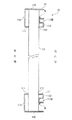
次に、本発明の第4実施形態を図7に基づいて説明する。
図7は、第4実施形態の面格子10の要部を示す縦断面図である。本実施形態の面格子10では、前述の第1実施形態と比較して、横材11の形態が相違し、その他の構成は同様である。以下、相違点について詳しく説明する。
【0037】
図7に示した本実施形態の面格子10では、横材11の上下方向の長さ寸法が第1実施形態と異なっている。すなわち、第1、第2側面部113,114の延出寸法が長くなっており、第1側面部113の折曲部113Aと外面部115との間隔部分の距離は第1実施形態と略同一となっている。このような、横材11は、例えば、面格子10の上下方向の寸法が大きく、横材11と縦桟12との固定強度を高めたい場合や、外観のデザイン上の要求から横材11の上下方向の寸法を大きくする場合等に採用される。
このような構成の面格子10の組み立て手順は、第1実施形態と略同様であり、挿通孔112および第1側面部113の折曲部113Aの2箇所と、外面部115の内側で縦桟12に対する位置決めがなされるようになっている。そして、挿通孔112と折曲部113Aとの縦桟12に沿った方向の距離が大きくなっているため、横材11および縦桟12の組み立て時における位置決めがより安定し、かつ、組み立て後の固定強度が高くなっている。
【0038】
このような本実施形態によれば、前述の(1)〜(7)の効果と合わせて次のような効果がある。
(10) 挿通孔112と折曲部113Aとの縦桟12に沿った方向の距離が大きくなっているので、横材11および縦桟12をより安定して位置決めでき、組立作業の作業効率をさらに向上させることができる。さらに、横材11および縦桟12の固定強度を高めることができる。
【0039】
(11) 横材11の上下方向寸法を大きくしても、第1側面部113の折曲部113Aと外面部115との間隔部分の距離は変わらず、室内側からの外観を損なわず、良好な外観を保持できる。
【0040】
なお、本発明を実施するための最良の構成、方法などは、以上の記載で開示されているが、本発明は、これに限定されるものではない。
すなわち、本発明は、主に特定の実施の形態に関して特に図示され、かつ、説明されているが、以上述べた実施の形態に対し、本発明の技術的思想および目的の範囲から逸脱することなく、形状、材質、数量、その他の詳細な構成において、当業者が様々な変形を加えることができる。
【0041】
例えば、前述の各実施形態では、面格子10が住宅の外壁1に取り付けられるものとしたが、これに限らず、住宅以外の建物や工作物等に取り付けられてもよく、また、外壁以外の内壁や間仕切り壁、屋根等に取り付けられてもよい。
また、前述の各実施形態では、支持材を水平方向に延びる横材11とし、桟材を上下方向に延びる縦桟12としたが、これに限らず、支持材を縦方向に向けて配置してもよく、また、適宜傾斜を有して配置してもよい。また、2本の支持材は、互いに平行である必要はなく、互いに角度を有して配置されていてもよい。
【0042】
また、前述の各実施形態では、横材11、縦桟12、およびブラケット13をSUS製とし、曲げ加工により形成するものとしたが、これに限らず、アルミ製や鋼製、合成樹脂製等であってもよい。アルミ製であれば、各部材を押出形材から形成することもでき、このようにすることで、加工手間を軽減し、より低コストで製造できるようになる。
また、前述の各実施形態では、横材11の第1側面部113と縦桟12の側面とを、溶接またはビス止めにより固定したが、これに限らず、溶着や接着、圧着等により固定されてもよく、また、固定用金具等を用いて固定されてもよい。
【0043】
また、前述の各実施形態では、横材11の交差面部111と第1、第2側面部113,114とを互いに交差する平面として形成したが、これに限らず、各々の部分を曲面状に形成してもよく、例えば、横材を全体略円筒状に形成することもできる。
また、前述の各実施形態では、横材11の外面部115に縦桟12の先端が当接するものとしたが、これに限らず、所定の間隔だけ離れて設けられていてもよい。この際、組み立て時において、位置決めスペーサ等を用い、縦桟に沿った方向についての横材および縦桟の位置決めを実施することができる。
【0044】
また、前述の各実施形態では、格子体を用いた面格子10について説明したが、本発明の格子体は面格子に限らず、階段、通路、バルコニー等に設けられる手摺りや、柵(フェンス)、門扉等に利用することも可能である。その場合でも、前述の各実施形態で説明した作用効果を奏することができる。
【0045】
【発明の効果】
以上に述べたように、本発明の格子体、およびこの格子体を用いた面格子によれば、組立作業の作業効率向上を図ることができ、かつ、外観を良好にできるという効果がある。
【図面の簡単な説明】
【図1】本発明の第1実施形態に係る面格子が設けられた開口部を示す横断面図である。
【図2】前記面格子の取付部分を拡大して示す分解斜視図である。
【図3】前記面格子の要部を示す斜視図である。
【図4】前記面格子の要部を示す縦断面図である。
【図5】本発明の第2実施形態に係る面格子の要部を示す縦断面図である。
【図6】本発明の第3実施形態に係る面格子の要部を示す縦断面図である。
【図7】本発明の第4実施形態に係る面格子の要部を示す縦断面図である。
【符号の説明】
10…面格子、11…支持材である横材、12…桟材である縦桟、13…ブラケット、111…交差面部、112…挿通孔、113…一方側の側面部である第1側面部、113A…折曲部、114…他方側の側面部である第2側面部、115…外面部。[0001]
TECHNICAL FIELD OF THE INVENTION
The present invention relates to a lattice body and a plane lattice using the lattice body.
[0002]
[Background Art]
2. Description of the Related Art Hitherto, a grid used for a surface grid attached to an outer wall opening of a building and a handrail, a fence, a gate, and the like provided on stairs, passages, balconies, and the like have been known. As such a lattice, a lattice composed of a frame fixed to a frame or the like and a plurality of vertical bars attached inside the frame has been proposed (for example, see Patent Document 1). . In the lattice body (grid material) described in Patent Literature 1, the upper frame material is formed to have a substantially C-shaped cross section that opens downward, and a vertical bar is inserted into the opening of the frame material, and the opening of the frame material is opened. The portions are pressurized from both the indoor and outdoor sides toward the vertical rail, and are welded and fixed to each other to be integrally formed.
[0003]
[Patent Document 1]
Japanese Utility Model Publication No. 52-3257
[0004]
[Problems to be solved by the invention]
However, in the lattice body described in Patent Literature 1, since the members are not stable when welding and fixing the members only by inserting the vertical bars into the C-shaped openings of the frame members, the frame members and the vertical bars are connected to each other. It is necessary to temporarily fix in the positioned state, and there is a problem that the working efficiency of the assembling work is low.
Further, since the welded portions of the frame member and the vertical bar are exposed on both sides of the frame material inside and outside, there is also a problem that the design of the appearance of the lattice body is impaired.
[0005]
SUMMARY OF THE INVENTION An object of the present invention is to provide a lattice body which can improve the work efficiency of an assembling operation and can improve the appearance, and a surface lattice using the lattice body.
[0006]
[Means for Solving the Problems]
The lattice body of the present invention is a lattice body including a pair of long support members provided at predetermined intervals and a plurality of crosspieces spanned between these support members, wherein each of the support members A cross-section having a plurality of insertion holes into which ends of the plurality of crosspieces are inserted, and extending from both side edges along the longitudinal direction of the cross-section in a direction away from other support members, respectively. And two side portions provided, wherein one of the two side portions is fixed by abutting a side surface of the crosspiece.
[0007]
According to the present invention, by inserting the crosspiece into the insertion hole provided in the crossing surface of the support, the crosspiece can be positioned in the longitudinal direction and the orthogonal direction of the support intersecting with the crosspiece. At the same time, by contacting one side surface of the support member with the side surface of the crosspiece, the support member comes into contact with the crosspiece at at least two places of the insertion hole and the side surface portion. Also, the crosspiece can be positioned. Therefore, when assembling the lattice, fixing work such as welding can be performed in a state where the support member and the crosspiece are stably positioned, and the work efficiency of the assembling work can be improved.
Also, by fixing the side surface portion formed on one side of the support material to the side surface of the crosspiece, for example, when both members are fixed by welding, a weld bead as a fixed portion is attached to the other side surface. Does not appear, and the appearance can be improved by setting the other side to the side more visible.
[0008]
Furthermore, since the side portions are continuously formed on both side edges of the intersection surface portion where the insertion hole is provided, the strength of the members around the insertion hole can be secured, so that a person who intends to intrude into the room has an insertion hole portion. It is possible to make it difficult to break the support material, and to improve the crime prevention. Further, in the conventional lattice body, the lower frame member and the vertical rail are not fixed, and a vertical frame member for connecting the upper and lower frame members is required. Since both of the support members are fixed to the crosspiece, a frame member for connecting these two support members can be eliminated, and the number of parts can be reduced. Further, in the lattice body of the present invention, since the two support members can be formed from the same component, the components can be shared.
[0009]
At this time, in the lattice body of the present invention, the one side portion has a bent portion that is substantially parallel to the intersection surface portion and is bent toward a side surface of the crosspiece. It is characterized by being in contact with the side of the material.
In such a configuration, the side portion formed on one side of the support member is bent toward the crosspiece, and this bent portion is abutted and fixed to the side surface of the crosspiece, so that the inside of the space between the two support members is fixed. Then, even from a position slightly distant from the lattice body, the fixed portion can be hidden from the bent portion so that the appearance can be further improved.
[0010]
Further, in the lattice body according to the present invention, the support member includes an outer surface portion formed continuously with the other side surface portion of the two side surface portions and arranged to face the intersection surface portion. The tip of the crosspiece is in contact with the crosspiece.
In such a configuration, by forming an outer surface portion where the tip of the crosspiece abuts on the side face formed on the other side of the support material, the tip of the crosspiece can be covered with the support material, For example, when the crosspiece is formed of a hollow pipe-shaped member, it is possible to prevent rainwater or the like from entering the inside of the crosspiece. In addition, by assembling the lattice body, by contacting the tip of the crosspiece with the outer surface of the support member, positioning in the direction along the crosspiece becomes possible, and the work efficiency of the assembling work can be further improved.
[0011]
Further, in the lattice body of the present invention, the two support members are vertically opposed to each other and are arranged substantially horizontally.
In such a configuration, by installing the two support members vertically and horizontally, it is possible to configure a general surface grid, handrail, fence, gate, etc., in which the crosspieces extend vertically. Since the support members are arranged vertically symmetrically, the appearance design can be unified, and the design can be improved.
In addition, in the conventional lattice body, if the upper and lower frame members are made common and the design is unified, the upper frame member can be turned upside down and arranged on the lower side. If the frame material is opened upward, it is difficult for the rainwater, etc., which has entered the inside of the frame material to be discharged, and this water will corrode the frame material or freeze in winter, causing damage to the frame material, etc. Causes inconvenience.
In the lattice body of the present invention, since the side portion of the lower support material extends downward from the intersection surface portion, rainwater or the like hardly enters the lower support material, and Even if it enters, it is immediately discharged. In addition, the side surface of the upper support material extends upward from the crossing surface portion, but since the crossing surface portion is provided with an insertion hole, rainwater or the like that has infiltrated the support material has an insertion hole. It is being discharged from. Therefore, in the lattice body of the present invention, since water does not easily accumulate inside the support material, damage due to corrosion or freezing can be prevented, and durability can be ensured.
[0012]
On the other hand, the surface lattice of the present invention is characterized by comprising any one of the lattices described above and a bracket for fixing the wall attached to two support members constituting the lattice.
According to the present invention, the same effects as those described above can be obtained in the surface grating. In addition, since the support member can be fixed to the wall via the wall fixing bracket, a frame member or the like for connecting the support members is unnecessary, and the number of components can be reduced.
[0013]
BEST MODE FOR CARRYING OUT THE INVENTION
[First Embodiment]
Hereinafter, a first embodiment of the present invention will be described with reference to the drawings.
1 to 4 show a surface grating 10 using the grating according to the present embodiment. FIG. 1 is a cross-sectional view showing an opening provided with a surface grating 10. FIG. 2 is an exploded perspective view showing, on an enlarged scale, a mounting portion of the
[0014]
As shown in FIG. 1, for example, the
[0015]
The
[0016]
As shown in FIGS. 2 to 4, the
[0017]
On the indoor side, which is one side of the
[0018]
On the other side of the
[0019]
As shown in FIG. 2, the
[0020]
The
The
[0021]
Next, an assembling procedure of the surface grating 10 having the above configuration will be described.
First, a plurality of
[0022]
In the
[0023]
According to this embodiment, the following effects can be obtained.
(1) The
[0024]
(2) Further, by fixing the
[0025]
(3) Further, by welding and fixing the
[0026]
(4) In the
[0027]
(5) Further, by forming an
[0028]
(6) Further, since the first and second side surfaces 113 and 114 of the
[0029]
(7) Since both the upper and
[0030]
[Second embodiment]
Next, a second embodiment of the present invention will be described with reference to FIG.
FIG. 5 is a longitudinal sectional view illustrating a main part of the surface grating 10 according to the second embodiment. The surface grating 10 of the present embodiment is different from the above-described first embodiment in the form of the first
[0031]
In the
The procedure for assembling the
[0032]
According to the present embodiment, the following effects are obtained in addition to the effects (1), (2), and (4) to (7).
(8) When forming the
[0033]
[Third embodiment]
Next, a third embodiment of the present invention will be described with reference to FIG.
FIG. 6 is a longitudinal sectional view showing a main part of the surface grating 10 of the third embodiment. The surface grating 10 of the present embodiment is different from the above-described first embodiment in the form of the first
[0034]
The surface grating 10 of the present embodiment shown in FIG. 6 is different from the first embodiment in the form in which the distal end side of the first
The procedure of assembling the
In the present embodiment, the first
[0035]
According to the present embodiment, the following effects are obtained in addition to the effects (1) to (7) described above.
(9) It is also possible to fix the
[0036]
[Fourth embodiment]
Next, a fourth embodiment of the present invention will be described with reference to FIG.
FIG. 7 is a vertical cross-sectional view illustrating a main part of the surface grating 10 of the fourth embodiment. The surface grating 10 of the present embodiment is different from the above-described first embodiment in the form of the
[0037]
In the surface grating 10 of the present embodiment shown in FIG. 7, the length of the
The procedure for assembling the
[0038]
According to the present embodiment, the following effects are obtained in addition to the effects (1) to (7) described above.
(10) Since the distance between the
[0039]
(11) Even if the vertical dimension of the
[0040]
Although the best configuration and method for carrying out the present invention have been disclosed in the above description, the present invention is not limited to this.
That is, the present invention has been particularly shown and described with particular reference to particular embodiments, but without departing from the spirit and scope of the present invention with respect to the embodiments described above. Those skilled in the art can make various modifications in the shape, material, quantity, and other detailed configurations.
[0041]
For example, in each of the above-described embodiments, the
Further, in each of the above-described embodiments, the support member is the
[0042]
In each of the above-described embodiments, the
Further, in each of the above-described embodiments, the first
[0043]
Further, in each of the above-described embodiments, the intersecting
Further, in each of the above-described embodiments, the tip of the
[0044]
Further, in each of the above-described embodiments, the
[0045]
【The invention's effect】
As described above, according to the lattice body of the present invention and the surface lattice using the lattice body, there is an effect that the work efficiency of the assembling work can be improved and the appearance can be improved.
[Brief description of the drawings]
FIG. 1 is a cross-sectional view showing an opening provided with a surface grating according to a first embodiment of the present invention.
FIG. 2 is an exploded perspective view showing, on an enlarged scale, a mounting portion of the surface grid.
FIG. 3 is a perspective view showing a main part of the surface grating.
FIG. 4 is a longitudinal sectional view showing a main part of the surface grating.
FIG. 5 is a longitudinal sectional view showing a main part of a surface grating according to a second embodiment of the present invention.
FIG. 6 is a longitudinal sectional view showing a main part of a surface grating according to a third embodiment of the present invention.
FIG. 7 is a longitudinal sectional view showing a main part of a surface grating according to a fourth embodiment of the present invention.
[Explanation of symbols]
DESCRIPTION OF
Claims (5)
前記各支持材は、前記複数の桟材の端部が挿通される複数の挿通孔を有した交差面部と、この交差面部の長手方向に沿った両側端縁から、他の支持材から離れる方向にそれぞれ延出された2つの側面部とを備え、
前記2つの側面部のうち、一方の側面部に前記桟材の側面が当接して固定されている格子体。A grid body including a pair of long support members provided at predetermined intervals and a plurality of crosspieces spanned between these support members,
Each of the support members has a crossed surface portion having a plurality of insertion holes into which ends of the plurality of crosspieces are inserted, and a direction separating from other support materials from both side edges along a longitudinal direction of the crossed surface portion. And two side portions respectively extended to
A lattice body in which the side surface of the crosspiece abuts and is fixed to one of the two side surface portions.
Priority Applications (1)
| Application Number | Priority Date | Filing Date | Title |
|---|---|---|---|
| JP2003077818A JP2004285657A (en) | 2003-03-20 | 2003-03-20 | Grille body, and grille for window using the same |
Applications Claiming Priority (1)
| Application Number | Priority Date | Filing Date | Title |
|---|---|---|---|
| JP2003077818A JP2004285657A (en) | 2003-03-20 | 2003-03-20 | Grille body, and grille for window using the same |
Publications (1)
| Publication Number | Publication Date |
|---|---|
| JP2004285657A true JP2004285657A (en) | 2004-10-14 |
Family
ID=33292477
Family Applications (1)
| Application Number | Title | Priority Date | Filing Date |
|---|---|---|---|
| JP2003077818A Pending JP2004285657A (en) | 2003-03-20 | 2003-03-20 | Grille body, and grille for window using the same |
Country Status (1)
| Country | Link |
|---|---|
| JP (1) | JP2004285657A (en) |
Cited By (2)
| Publication number | Priority date | Publication date | Assignee | Title |
|---|---|---|---|---|
| JP2006266016A (en) * | 2005-03-25 | 2006-10-05 | Fukuvi Chem Ind Co Ltd | Mounting tool for window grille and window grille unit including the same |
| JP2008156830A (en) * | 2006-12-21 | 2008-07-10 | Asahi Fiber Glass Co Ltd | Mounting structure for crosspieces and support structure for floor insulation |
-
2003
- 2003-03-20 JP JP2003077818A patent/JP2004285657A/en active Pending
Cited By (2)
| Publication number | Priority date | Publication date | Assignee | Title |
|---|---|---|---|---|
| JP2006266016A (en) * | 2005-03-25 | 2006-10-05 | Fukuvi Chem Ind Co Ltd | Mounting tool for window grille and window grille unit including the same |
| JP2008156830A (en) * | 2006-12-21 | 2008-07-10 | Asahi Fiber Glass Co Ltd | Mounting structure for crosspieces and support structure for floor insulation |
Similar Documents
| Publication | Publication Date | Title |
|---|---|---|
| JP4767881B2 (en) | Fence beam mounting structure | |
| JP4886724B2 (en) | Architectural exterior louver | |
| JP4679435B2 (en) | Wiring storage structure for installations on the roof | |
| JP5393135B2 (en) | Eaves structure | |
| JP2006249677A (en) | Outdoor structure | |
| JP2004285657A (en) | Grille body, and grille for window using the same | |
| JP2009221788A (en) | Curtain wall and its construction method | |
| JP4914161B2 (en) | Vertical beam mounting structure | |
| JP5437758B2 (en) | Panel mounting structure and panel mounting method | |
| JP6462219B2 (en) | handrail | |
| EP2080850A1 (en) | Anchoring mechanism for enclosures | |
| JP5158685B2 (en) | Mounting member mounting structure and simple structure | |
| JP4530219B2 (en) | Outdoor structure | |
| JP3989274B2 (en) | Underground structure for buildings | |
| JP4424547B2 (en) | Panel body | |
| JP3764078B2 (en) | Mounting structure and mounting method of overhang structure | |
| JPH11270197A (en) | Protective fence | |
| JPH11280141A (en) | Balcony floor unit mounting structure | |
| JP4704124B2 (en) | Handrail component fitting | |
| JP5529556B2 (en) | Handrail support bracket and handrail | |
| JP3888270B2 (en) | Seismic reinforcement frame for openings | |
| JPH11210273A (en) | Fence and installation thereof | |
| JP2001193202A (en) | Curtain wall | |
| JP3705069B2 (en) | fence | |
| JP4114872B2 (en) | Fence |
Legal Events
| Date | Code | Title | Description |
|---|---|---|---|
| A621 | Written request for application examination |
Effective date: 20050317 Free format text: JAPANESE INTERMEDIATE CODE: A621 |
|
| RD02 | Notification of acceptance of power of attorney |
Free format text: JAPANESE INTERMEDIATE CODE: A7422 Effective date: 20070704 |
|
| RD02 | Notification of acceptance of power of attorney |
Effective date: 20070809 Free format text: JAPANESE INTERMEDIATE CODE: A7422 |
|
| A977 | Report on retrieval |
Effective date: 20071206 Free format text: JAPANESE INTERMEDIATE CODE: A971007 |
|
| A131 | Notification of reasons for refusal |
Effective date: 20071211 Free format text: JAPANESE INTERMEDIATE CODE: A131 |
|
| A521 | Written amendment |
Effective date: 20080205 Free format text: JAPANESE INTERMEDIATE CODE: A523 |
|
| A131 | Notification of reasons for refusal |
Free format text: JAPANESE INTERMEDIATE CODE: A131 Effective date: 20080527 |
|
| A02 | Decision of refusal |
Free format text: JAPANESE INTERMEDIATE CODE: A02 Effective date: 20081007 |