JP2004287635A - Production line operation status analysis device, operation status analysis method, operation status analysis program, and operation status analysis system - Google Patents
Production line operation status analysis device, operation status analysis method, operation status analysis program, and operation status analysis system Download PDFInfo
- Publication number
- JP2004287635A JP2004287635A JP2003076718A JP2003076718A JP2004287635A JP 2004287635 A JP2004287635 A JP 2004287635A JP 2003076718 A JP2003076718 A JP 2003076718A JP 2003076718 A JP2003076718 A JP 2003076718A JP 2004287635 A JP2004287635 A JP 2004287635A
- Authority
- JP
- Japan
- Prior art keywords
- data
- state
- operation status
- operating state
- production line
- Prior art date
- Legal status (The legal status is an assumption and is not a legal conclusion. Google has not performed a legal analysis and makes no representation as to the accuracy of the status listed.)
- Granted
Links
Images



Classifications
-
- Y—GENERAL TAGGING OF NEW TECHNOLOGICAL DEVELOPMENTS; GENERAL TAGGING OF CROSS-SECTIONAL TECHNOLOGIES SPANNING OVER SEVERAL SECTIONS OF THE IPC; TECHNICAL SUBJECTS COVERED BY FORMER USPC CROSS-REFERENCE ART COLLECTIONS [XRACs] AND DIGESTS
- Y02—TECHNOLOGIES OR APPLICATIONS FOR MITIGATION OR ADAPTATION AGAINST CLIMATE CHANGE
- Y02P—CLIMATE CHANGE MITIGATION TECHNOLOGIES IN THE PRODUCTION OR PROCESSING OF GOODS
- Y02P90/00—Enabling technologies with a potential contribution to greenhouse gas [GHG] emissions mitigation
- Y02P90/02—Total factory control, e.g. smart factories, flexible manufacturing systems [FMS] or integrated manufacturing systems [IMS]
Landscapes
- General Factory Administration (AREA)
- Testing And Monitoring For Control Systems (AREA)
Abstract
【課題】生産ラインを構成する各工程に専用の回路やプログラムを要せず、各工程の状態を表す信号に基づいて生産ラインの稼動状況を解析することである。
【解決手段】生産ラインの稼動状況解析システム10は、生産ラインを構成する各生産設備20と、これらの動作状態のデータを収集するデータ収集装置30と、データ蓄積サーバ50と、稼動状況解析装置60を含む。稼動状況解析装置60は、データ取得部100と稼動状態データ算出部150の機能を有し、稼動状態関数に取得した複数の動作状態データを入力して、所望の稼動状態データを算出する。稼動状態関数は、複数の動作状態を演算子で組み合わせることで任意に構成することができる。稼動状態関数を用いて、実生産中状態算出モジュール152以下の算出モジュールの機能が実行される。
【選択図】 図3An object of the present invention is to analyze an operation state of a production line based on a signal indicating a state of each step without requiring a dedicated circuit or a program for each step constituting a production line.
A production line operation status analysis system includes a production line, a production facility, a data collection device for collecting data on an operation state of the production line, a data storage server, and an operation status analysis device. 60. The operation state analysis device 60 has the functions of the data acquisition unit 100 and the operation state data calculation unit 150, and inputs desired operation state data to the operation state function to calculate desired operation state data. The operating state function can be arbitrarily configured by combining a plurality of operating states with an operator. Using the operation state function, the functions of the calculation modules below the actual production state calculation module 152 are executed.
[Selection diagram] FIG.
Description
【0001】
【発明の属する技術分野】
本発明は、生産ラインの稼動状況解析装置に係り、特に、複数の生産設備で構成される生産ラインの稼動状況についてデータ収集装置により収集されたデータを用いて解析する稼動状況解析装置に関する。
【0002】
【従来の技術】
複数の工程によって構成される生産ラインにおいて、生産計画通りの生産を継続的に行うには、各工程の稼動状態の評価や、生産ライン全体の稼動評価を適切に行うことが重要である。各工程の状態を判別する手段として、各工程を構成する設備の動作を制御するPLC(Programmable Logic Controller)の信号を記録する方法がある。しかし、事前に設備ごとに状態を表す信号を出力する回路をPLCプログラムに追加し、記録した信号を独立に解析しただけでは設備の状態を正確には判別できないので、状態遷移の規則性を用いて状態の推定精度を上げることが行われる。例えば、特許文献1には、複数の状態を有する設備のシーケンスコントローラに1対1でパーソナルコンピュータ(Personal Computer:PC)を接続し、シーケンスコントローラが把握する遷移情報に対応させて設備の稼動状況をサンプリングし、得られた状態間の遷移を判定することが開示される。
【0003】
【特許文献1】
特開平7−104838号公報
【0004】
【発明が解決しようとする課題】
上記のように、各工程の状態を表す信号を出力する回路をPLCプログラムに追加することは、現場において各工程1つごとに設定し、動作確認を行う必要があり、また、各工程ごとに内部信号のアドレスが異なるため、状態を判別するためには各工程設備ごとの専用プログラムの作成を要するので、時間とコストがかかる。
【0005】
また、このように、各工程ごとに回路、プログラムを追加しても、これらは各工程に専用であるので、システムの拡張性や汎用性に乏しい。例えば、複数の工程に拡張して回路、プログラムを追加することが困難であるため、各工程の稼動状態からさらに進んで関連する複数の工程の総合的な状態、あるいは生産ライン全体の稼動状態を把握することが難しい。
【0006】
また、各工程に設けられる回路、プログラムに汎用性がないため、出力される信号は専用の目的にのみ用いられ、複数の信号を任意に組み合わせて別の状態の表し方等を行い、さらに発展的な稼動状況の把握をすることができない。
【0007】
本発明の目的は、かかる従来技術の課題を解決し、生産ラインを構成する各工程に専用の回路やプログラムを要せず、各工程の状態を表す信号に基づいて稼動状況を解析できる生産ラインの稼動状況解析装置、稼動状況解析方法、稼動状況解析プログラム及び稼動状況解析システムを提供することである。他の目的は、複数の信号を任意に組み合わせることで稼動状態を解析できる汎用性の高い生産ラインの稼動状況解析装置、稼動状況解析方法、稼動状況解析プログラム及び稼動状況解析システムを提供することである。さらに他の目的は、特別な回路やプログラムを要することなく、複数の工程にまたがって稼動状態を解析できる生産ラインの稼動状況解析装置、稼動状況解析方法、稼動状況解析プログラム及び稼動状況解析システムを提供することである。以下の請求項に記載される発明は、上記目的の少なくとも1つを達成するために提供される。
【0008】
【課題を解決するための手段】
1.稼動状態関数
最初に、稼動状態関数について説明する。稼動状態関数とは、複数の動作状態を演算子により結びつけて構成される関数で、例えば、動作状態をX1,X2,X3として、X1,X2,X3をAND、OR等の演算子で結びつけて構成される関数で、一例をあげれば、Y0=[X1ORX2]ANDX3 等である。
【0009】
生産設備の動作状態、上記の例でX1,X2,X3は、PLCの信号を収集することで得られる。動作状態の他に、なぜ稼動状態関数Y0によって新しい状態を算出する必要があるか、というと、それは、PLC等から収集される動作状態のみでは、設備の動的な状態である稼動状態を十分に表せないことが多いからである。
【0010】
例えば、一例として、生産設備における作業要素である1つのシリンダの動作状態と稼動状態を取り上げる。いま、シリンダが前進中という稼動状態を把握したいとすると、PLCから、シリンダの動作状態としてシリンダ前進指示信号X20を収集し、その値が1(前進指示有り)か0(前進指示無し)を見る。ところで、シリンダ前進指示信号X20が1であれば、必ずシリンダは前進中であるかというと、必ずしもそうでなく、例えば、まだ前進を開始していない場合が含まれる。したがって、前進中という稼動状態を得るには、さらにシリンダ前進端検出信号X21を調べ、その値が0(シリンダ前進端が検出されず)であることを確かめねばならない。
【0011】
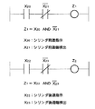
この場合、2つの動作状態X20,X21をそれぞれ独立に調べることでシリンダ前進中か否かを判断することもできるが、X20と(NOTX21)とをANDで結びつけた関数をつくり、この関数を「前進中」稼動状態関数Z1とすればよい。「前進中」稼動状態関数Z1は、2つの動作状態X20,X21を演算子ORとNOTを用いて結びつけたものである。したがって、時々刻々における2つの動作状態X20,X21のデータを対として入力することで、(前進指示有り)かつ(シリンダ前進端が検出されず)を満たすか否かを演算し、「シリンダ前進中」か否かの稼動状態データを時々刻々出力することができる。
【0012】
図1は、シリンダの動作状態とシリンダの稼動状態の関係を、ラダー回路図により表現した例である。各動作状態X20,X21,X22,X23は接点のシンボルで示し、稼動状態関数Z1,Z2はコイルのシンボルで示してある。図1に示すように、シリンダ前進指示X20とシリンダ前進端検出X21の2つの動作状態を演算子で結びつけて「前進中」稼動状態関数Z1を構成でき、シリンダ後退指示X22とシリンダ後退端検出X23の2つの動作状態を演算子で結びつけて「後退中」稼動状態関数Z2を構成できる。
【0013】
図2は、各動作状態X20,X21,X22,X23のデータを時系列で稼動状態関数に入力し、「前進中」稼動状態関数Z1の出力データz1及び「後退中」稼動状態関数Z2の出力データz2をタイムチャートとして出力する例を示す図である。図2(a)は、標準的なシリンダの稼動状態を示し、図2(a)は、「後退中」に問題がある例である。これらのデータから、「後退中」に問題があることの抽出とともに、例えば「前進時間」「後退時間」等の定量的な解析を行うこともできる。
【0014】
このように、複数の動作状態を演算子により組み合わせることで、任意の稼動状態関数を構成でき、この稼動状態関数を用いて、複数の動作状態データを入力すれば、動作状態データのみでは把握できない新しい状態としての稼動状態データを出力することができる。
【0015】
稼動状態解析目的に応じ、稼動状態関数の関数形を構成することで、所望の稼動状態データを容易に得ることができる。また、時系列に複数の動作状態データを入力すれば、時系列の稼動状態データが出力されるので、より定量的な稼動状態データを得ることができる。
【0016】
複数の動作状態は、生産設備のPLCの信号から収集することができ、稼動状態関数は、任意の関数形を作ることができるので、稼動状態関数を用いることで稼動状態解析の汎用性を著しく高めることができる。すなわち、所望の稼動状態データを得るための専用の回路や、専用のプログラムを各設備ごとに設ける必要がなく、単に、動作状態データを収集して稼動状態関数に入力すれば、所望の稼動状態データを得ることができる。
【0017】
稼動状態関数を、上記のようにディジタルデータの論理演算結果として構成するほかに、時間管理関数とすることもできる。例えば、図2の場合、シリンダ後退時間t2を閾値関数で判断し、出力することができる。この例で、閾値関数を、2sec<t2<3sec等とすれば、後退時間がこの範囲に入っていないときに、後退時間稼動状態データとして0を出力させることができる。
【0018】
2.課題解決手段
本発明に係る稼動状況解析装置は、データ収集装置により収集される生産ラインの各作業要素の動作状態を表す動作状態データに基づき、生産ラインの稼動状況を解析する稼動状況解析装置であって、データ収集装置により収集された複数の動作状態データを取得するデータ取得手段と、複数の動作状態を演算子によって組み合わせた稼動状態関数を用い、複数の動作状態データを稼動状態関数に入力し、生産ラインの稼動状態を表す稼動状態データを算出する稼動状態データ算出手段と、を備えることを特徴とする。
【0019】
上記構成により、稼動状態データの算出に「1.稼動状態関数」のところで述べた稼動状態関数を用いる。稼動状態関数に入力される動作状態データは、データ収集装置により、生産ラインの各作業要素の動作状態データが収集される。生産ラインの各作業要素の動作状態データは、例えば、各工程ごとに設けられたPLCの信号や、センサ信号をそのまま用いることができる。上記のように、稼動状態関数は、動作状態と演算子で構成されるので、動作状態の種類を代えること、あるいは演算子の種類を代えること等で、任意の関数を作り出すことができる。したがって、複数の信号を任意に組み合わせることで稼動状態を解析でき、解析システムの汎用性が高い。また、稼動状態を表す信号を出力するための専用の回路やプログラムを必要としない。
【0020】
また、稼動状態データ算出手段は、生産ラインの各工程の稼動状態を解析するため、当該工程とその前後の工程を含む複数の工程における動作状態データを稼動状態関数に入力し、稼動状態データとして、各工程の稼動状態を表す工程稼動状態データを算出することが好ましい。
【0021】
稼動状態関数を構成する複数の動作状態は、同一工程内の複数の動作状態のみに限られない。上記構成により、当該工程と前後の工程を含む複数の工程における動作状態データを稼動状況関数に入力し、各工程の工程稼動状態稼動データを算出する。この場合の稼動状況関数は、複数の工程における動作状態を演算子により組み合わせて構成される。したがって、特別な回路やプログラムを要せずに、複数の工程にまたがった稼動状態を解析できる。
【0022】
また、稼働状態データ算出手段は、各工程の稼動状態として、実生産中を表す実生産中状態、または異常停止中を表す異常停止中状態、または工具交換中を表す工具交換状態、または品質チェック中を表す品質チェック状態、または後工程ワークが詰まっているむだ状態を表す後工程フル状態、または前工程にワークがないむだ状態を表す前工程空き状態のいずれか1の工程稼動状態について工程稼動状態データを算出することが好ましい。
【0023】
各工程は複数の稼動状態を有している。各工程の稼動状態の区分としては、実生産中状態、異常停止中状態、工具交換状態、品質チェック状態、後工程フル状態、前工程空き状態等の複数の稼動状態に区分することができる。各工程の稼動状態は、これらの各稼動状態のそれぞれが全体に占める割合を解析することで定量的に把握できる。例えば、ある工程は実生産中状態の比率が高く、稼動状況が順調であることや、別の工程は異常停止中状態の比率が高く、ネック工程となっていること等が解析できる。
【0024】
上記構成により、上記複数の工程稼動状態のうち、少なくとも1つの工程稼動状態データについて、当該工程と前後の工程を含む複数の工程における動作状態データを稼動状態関数に入力して算出する。上記複数の工程稼動状態全部を稼動状態関数により算出してもよい。稼動状態関数を用いることで、当該工程と前後の工程を含む複数の工程における動作状態データの入力のみで工程稼動状態を算出でき、工程の稼動状態を表す信号を出力するための各工程に専用の回路やプログラム、あるいは工程にまたがる特別の回路やプログラムを必要としない。
【0025】
また、稼働状態データ算出手段は、当該工程におけるワーク有無状態データと、当該工程の前工程におけるワーク有無状態データと、当該工程の後工程におけるワーク有無状態データと、を含む複数の動作状態データに基づいて各工程の実生産中状態を表す工程稼動データを算出することが好ましい。
【0026】
実生産中状態について、当該工程にワークが有る状態を把握したのみで判断するのは不十分である。なぜならば、当該工程にワークがあっても、ワークが加工や組み立て等の実作業を受けることなく後工程がフルワークのため待機中であることや、実作業を行っていても、その作業がはかどらず、前工程においてワークを待機させてしまっている場合が含まれるためである。上記構成により、当該工程及び前後の工程におけるワーク有無の動作状態データに基づいて、当該工程の実生産中状態を算出する。したがって、複数の工程にまたがる解析により正しく得られる実生産中状態データを、特別な回路やプログラムを用いることなく算出できる。
【0027】
また、稼働状態データ算出手段は、当該工程における作業完了の有無状態データと、当該工程の後工程におけるワーク有無状態データと、を含む複数の動作状態データに基づいて各工程の後工程フル状態を表す工程稼動データを算出することが好ましい。
【0028】
後工程フル状態について、当該工程の後工程にワークが有る状態を把握したのみで後工程に無駄があると判断するのは不十分である。なぜならば、後工程にワークが有っても、当該工程がまだ実作業を完了していなければ、無駄時間とならないためである。上記構成により、当該工程及び後工程における動作状態データに基づいて、後工程フル状態を算出する。したがって、複数の工程にまたがる解析により正しく得られる後工程フル状態データを、特別な回路やプログラムを用いることなく算出できる。
【0029】
また、稼働状態データ算出手段は、当該工程におけるワーク有無状態データと、当該工程の前工程におけるワーク有無状態データと、を含む複数の動作状態データに基づいて各工程の前工程空き状態を表す工程稼動データを算出することが好ましい。
【0030】
前工程空き状態について、当該工程の前工程にワークが無い状態を把握したのみで前工程に無駄があると判断するのは不十分である。なぜならば、前工程にワークが無くても、当該工程にワークがあれば、無駄時間とならないためである。上記構成により、当該工程及び前工程におけるワーク有無の動作状態データに基づいて、前工程空き状態を算出する。したがって、複数の工程にまたがる解析により正しく得られる前工程空き状態データを、特別な回路やプログラムを用いることなく算出できる。
【0031】
また、データ取得手段は、時系列に従った動作状態データを取得し、稼働データ算出手段は、取得された時系列に従った動作状態データに基づき、時系列に従った稼動状態データを算出し、稼動状態の経時変化を解析することが好ましい。経時変化の解析により、稼動状態データをより定量的に把握できる。また、専用の回路及びプログラムを要せずに、稼動状態の時系列解析を行うことができる。
【0032】
また、本発明に係る稼動状況解析方法は、データ収集装置により収集される生産ラインの各作業要素の動作状態を表す動作状態データに基づき、生産ラインの稼動状況を解析する稼動状況解析方法であって、データ収集装置により収集された複数の動作状態データを取得するデータ取得ステップと、複数の動作状態を演算子によって組み合わせた稼動状態関数を用い、複数の動作状態データを稼動状態関数に入力し、生産ラインの稼動状態を表す稼動状態データを算出する稼動状態データ算出ステップと、を備えることを特徴とする。
【0033】
また、本発明に係る稼動状況解析プログラムは、データ収集装置により収集される生産ラインの各作業要素の動作状態を表す動作状態データに基づき、生産ラインの稼動状況を解析する稼動状況解析プログラムであって、稼動状況解析装置に、データ収集装置により収集された複数の動作状態データを取得するデータ取得処理手順と、複数の動作状態を演算子によって組み合わせた稼動状態関数を用い、複数の動作状態データを稼動状態関数に入力し、生産ラインの稼動状態を表す稼動状態データを算出する稼動状態データ算出処理手順と、を実行させることを特徴とする。
【0034】
また、本発明に係る稼動状況解析システムは、生産ラインの各工程ごとに設けられ、生産ラインを構成する各作業要素の動作状態を表す動作状態データを収集して出力する複数のデータ収集装置と、各データ収集装置から出力されるデータを受け取り、蓄積するデータ蓄積サーバと、データ蓄積サーバから、複数の動作状態データを取得し、複数の動作状態を演算子によって組み合わせた稼動状態関数を用い、取得した複数の動作状態データを稼動状態関数に入力することで、生産ラインの稼動状態を表す稼動状態データを算出する稼動状況解析装置と、を含むことを特徴とする。
【0035】
上記構成により、生産ラインを構成する各作業要素の動作状態データの収集は、まず各工程に設けられたデータ収集装置が行う。データ収集装置は、各作業要素の動作状態データとして、例えば、各工程を構成する生産設備の動作を制御する複数の制御素子の信号、各種センサの信号のデータ等を収集する。そして、データ収集装置で収集されたデータがデータ蓄積サーバによって記憶される。したがって、各工程単位に整理された動作状態データがデータ蓄積サーバにより蓄積されるので、データ蓄積サーバの負担が軽減される。例えば、各工程において、ワークに対する処理が終わるごとに、動作状態データをまとめてデータ蓄積サーバに送ることができ、区切りのよいデータ蓄積を少ない負担で行うことができる。また、生産ラインの構成が変動しても、工程単位で区切れるので、データ収集のシステムに柔軟性を持たせることができる。
【0036】
【発明の実施の形態】
以下に図面を用いて、本発明に係る実施の形態につき詳細に説明する。以下では、車両用のエンジン部品を生産する部品生産ラインを例として取り上げて説明するが、生産ラインとしては、複数の生産設備あるいは工程から構成される生産ラインであれば、エンジン部品生産ライン以外であってもよい。例えば、エンジン部品以外の部品の生産ライン、組み立てライン、検査ライン等でもよく、また、車両用の生産ラインに限られない。
【0037】
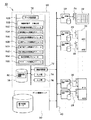
図3は、生産ラインの稼動状況解析システム10の構成を示すブロック図である。稼動状況解析システム10は、生産ラインを構成する各生産設備20と、各生産設備20の異常状態を表示する異常表示装置22と、各生産設備20及び異常表示装置22にそれぞれ接続され、これらの動作状態のデータを収集するデータ収集装置30と、各データ収集装置30とネットワーク40で接続されるデータ蓄積サーバ50と、やはりネットワーク40に接続される稼動状況解析装置60を含む。
【0038】
各生産設備20は、エンジン部品を完成するための各加工機械、例えばマシニングセンタ、旋盤、ドリル等、付属部品を取り付ける組み立て機械、検査機械、ワーク搬送機構等で構成され、数十台の生産設備20が一体となってエンジン部品生産ラインを構成する。
【0039】
各生産設備20は、その目的とする作業を行うために複数の作業要素を備え、それらの作業要素は複数の制御素子によりその動作が制御され、複数のセンサによってその位置等が検出される。例えば、複数のシリンダヘッドを用いてワークを順次移動させる場合を例にとると、各シリンダヘッドが作業要素で、各シリンダヘッドを駆動する油圧アクチュエータあるいはモータの動作をON/OFFする各リレーが制御素子に相当し、各シリンダヘッドの位置を検出するリミットスイッチ等がセンサにあたる。これら複数のリレー等によって各生産設備20が所定の動作を行うようにシーケンスコントロールが行われる。
【0040】
ディジタル信号によりシーケンスコントロールを行うものとして、各生産設備にはPLC24が設けられる。PLC24における各ON/OFF信号のデータは、生産設備20の動作を制御する制御素子の動作状態を表すディジタルデータとして、通信線26を介しデータ収集装置30に出力される。また、各種センサからは、生産設備の作業要素の動作状態を表すアナログ信号として、図示されていないアナログ信号出力インタフェイスと通信線28とを介し、データ収集装置30に出力される。
【0041】
これらの動作状態を表す動作状態データは、1つの生産設備20内の複数の作業要素それぞれの動作状態に対応するもののほか、例えば生産設備にワークが搬入されるタイミング、位置あるいは生産設備からワークが搬出されるタイミング、位置等のように、生産設備をいわば1つの作業要素としてその動作状態をあらわすものを含む。また、複数の生産設備でもって1つのまとまった工程とする方が便利な場合には、複数の設備を含む工程そのものをいわば1つの作業要素としてその動作状態を表すものを含む。
【0042】
異常表示装置22は、各工程の現在の状況を一目でわかるように表示する装置で、例えば、各工程に対応するランプを2次元配列し、異常の内容に応じて色を異ならせてランプを点灯するいわゆる「あんどん」と呼ばれるものを用いることができる。例えば、工程が異常停止のときは「赤」を点灯し、工具交換や部品補給等の必要があるときは「黄」を点灯して予報し、実際に作業者が工具交換等の実施をしている停止のときは「青」を点灯する等の表示を行うことができる。
【0043】
異常表示装置22の点灯は、異常表示装置22に設けられたPLC24により制御される。異常表示装置22に設けられたPLC24には、各生産設備20からの動作状態データが、図示されていない信号線を介して入力される。また、異常表示装置22に設けられたPLC24からは、異常表示装置22の作業要素、例えば、各ランプについてのON/OFF信号が、動作状態データとして、データ収集装置30に出力される。
【0044】
データ収集装置30は、各工程ごとに設けられ、各工程の作業要素の動作状態データを収集する装置で、一般的なPCで構成することができる。なお、上記のように、異常表示装置22用にもデータ収集装置30が接続されて設けられる。また、1つの工程が1つの生産設備で構成されるときは各生産設備ごとにデータ収集装置30が1台ずつ接続され、上記のように、複数の生産設備でもって1つの工程とするのが便利なときは、その工程に1台のデータ収集装置30が接続される。
【0045】
データ収集装置30は、対応するPLC24及びアナログ出力インタフェイスとの間で通信線26,28を介して交信し、必要な動作状態データを採取し、採取したデータを自らに転送することでデータの収集を実行する。データの収集は、収集するデータの種類を規定するデータ収集設定ファイル及び収集する期間を規定する収集条件設定ファイル等に登録された内容に従って、データ収集プログラムを実行することで行われる。
【0046】
データ収集装置30は、ネットワーク40を介し、所定のタイミング、例えば一定のサンプル数あるいは任意の動作が終了した時点等のタイミングで、収集した動作状態データをデータ蓄積サーバ50に転送する装置で、例えば一般的なパーソナルコンピュータ等で構成できる。所定のタイミングとして、生産装置20から収集したデータについては、例えば、ワークに対する処理が終わるごと等とすることもできる。また、異常表示装置22から収集したデータについては、例えば、生産ラインの稼動が終了した時点あるいは生産ロット等の切り替わり時点等のタイミングで転送してもよい。データの転送は、適当なファイル転送プロトコル(例えば、File Transfer Protocol:FTPを使用)に従い、そのプラグラムを実行することで行われる。未転送データを格納するために、データ収集装置30には記憶装置が設けられる。
【0047】
データ蓄積サーバ50は、ネットワーク40を介して各データ収集装置30と交信し、各データ収集装置30から動作状態データ等を収集し蓄積するサーバである。各データ収集装置30との間のデータ転送は、上記のようにファイル転送プログラムを実行することで行われる。受け取ったデータの分類と蓄積は、データ分類を規定するサーバ設定ファイルに従い、データサーバプログラムを実行することで行われる。
【0048】
稼動状況解析装置60は、データ蓄積サーバ50から必要なデータを取得し、処理して生産ラインの稼動状況を解析する装置で、一般的なコンピュータで構成できる。具体的には、ユーザが希望する解析メニューや設定項目を指定することで、データ蓄積サーバ50から必要な動作状態データを取得し、指定された解析メニュー等に対応する処理を実行して、生産ラインの稼動状況を定量的に解析して出力する機能を有する。データに対して解析メニュー等に対応する処理を行うには、ソフトウエアを用いることができ、対応する解析プログラムを実行することで所定の処理を行うことができる。処理の一部をハードウエアで実行させることもできる。
【0049】
稼動状況解析装置60は、CPU70と、ネットワーク40を介してデータ蓄積サーバ50と交信する通信制御部72と、ユーザが解析メニューまたは設定項目の指定を行うキーボード等の入力部74と、解析された生産ラインの稼動状況を表示するディスプレイ等の出力部76と、稼動状態関数のファイル80を記憶するハードディスク等の外部記憶装置78とを含み、これらは相互に内部バスにより接続される。
【0050】
CPU70の中のデータ取得部100は、通信制御部72を介し、データ蓄積サーバ50に必要なデータの転送を要求し、それを取得する機能を有する。必要なデータは、ユーザの指定する解析メニューの種類により異なる。
【0051】
稼動状態データ算出部150は、データ蓄積サーバ50から必要な動作状態データを取得し、稼動状態関数を用いて稼動状態データを算出する機能を有する。稼動状態データ算出部150の中の実生産中状態算出モジュール152以降アクチュエータ状態算出モジュール166までは、ユーザが指定した解析メニューの種類に対応してそれぞれの稼動状態データを算出する機能を有する。ユーザが指定した解析メニューの種類に対応する稼動状態関数は、外部記憶装置78のファイル80から読み出される。稼動状態データの算出の内容については、図4以降を用い、具体例に即して説明する。
【0052】
実生産中状態算出モジュール152は、ユーザが「実生産中状態算出」のメニューを指定し、当該工程を特定したときに実行される稼動状態解析処理の機能である。具体的には、当該工程及び前後の工程の動作状態データを取得し、当該工程の稼動状態として、実生産中か否かの稼動状態データを算出する機能を有する。
【0053】
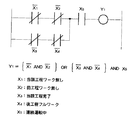
図4は、実生産中の稼動状態を出力する稼動状態関数Y1について、図1に示したと同様のシンボルを用いて、各動作状態として、当該工程ワーク無しX1、前工程ワーク無しX2、当該工程完了X3、後工程フルワークX4、連続運転中X5との関係を表したものである。図4に示すように、各動作状態をAND、OR、NOTで結びつけて、(当該工程ワーク有り)かつ(前工程ワーク有り)の状態と、(当該工程完了未だ)かつ(後工程フルワークでない)の状態のいずれか、であって、かつ(連続運転中)のときを表す稼動状態関数Y1を用いて実生産中を算出することができる。
【0054】
すなわち、実生産中とは、無駄がなく実作業を行っている稼動状態であるので、(連続運転中)だけでは足りず、(当該工程ワーク有り)かつ(前工程ワーク有り)であって前工程との関係で無駄がないか、(当該工程完了未だ)かつ(後工程フルワークでない)であって後工程との関係で無駄がないことが必要である。この実生産中稼動状態を把握するには、5つの動作状態データを監視する必要があるが、稼動状態関数Y1を用いることで、5つの動作状態データを時系列で収集し、これらを稼動状態関数Y1に入力すれば、実生産中稼動状態データを時系列で出力することができる。図5に、時系列の各動作状態X1,X2,X3,X4,X5のデータと、実生産中稼動状態関数Y1の出力データの例を示す。
【0055】
異常停止中状態算出モジュール154は、ユーザが「異常停止中状態算出」のメニューを指定し、当該工程を特定したときに実行される稼動状態解析処理の機能である。具体的には、当該工程の複数の動作状態データを取得し、当該工程の稼動状態として、異常停止中か否かの稼動状態データを算出する機能を有する。
【0056】
図6は、異常停止中の稼動状態を出力する稼動状態関数Y2と、各動作状態として、連続運転中X5、異常信号X6との関係を図1と同様の表記法で表したものである。図6に示すように、各動作状態をANDで結びつけて、(連続運転中でない)かつ(異常)の状態のときを異常停止中として算出することができる。
【0057】
すなわち、異常停止中とは、異常のために工程が停止している稼動状態であるので、異常信号が出ている動作状態では足りず、また、工程が停止している動作状態だけでは足りない。したがって、2つの動作状態をANDで結びつけて(連続運転中でない)かつ(異常)を表す稼動状態関数Y2を構成し、2つの動作状態データを時系列で収集し、これらを稼動状態関数Y2に入力して、異常停止中稼動状態データを時系列で出力することができる。
【0058】
工具交換状態算出モジュール156は、ユーザが「工具交換状態算出」のメニューを指定し、当該工程を特定したときに実行される稼動状態解析処理の機能である。具体的には、当該工程の複数の動作状態データを取得し、当該工程の稼動状態として、工具交換中か否かの稼動状態データを算出する機能を有する。
【0059】
図7は、工具交換中の稼動状態を出力する稼動状態関数Y3と、各動作状態として、工具交換予報X7、個別交換信号X8との関係を図1と同様の表記法で表したものである。図7に示すように、各動作状態をANDで結びつけて、(工具交換予報有り)かつ(個別交換中)の状態のときを工具交換中として算出することができる。
【0060】
すなわち、工具交換中とは、工具交換予報が出て、実際に作業者等が工具交換を行っている稼動状態であるので、工具交換予報が出ている動作状態では足りない。そこで、2つの動作状態をANDで結びつけて(工具交換予報あり)かつ(個別交換)を表す稼動状態関数Y3を構成し、2つの動作状態データを時系列で収集し、これらを稼動状態関数Y3に入力して、工具交換中稼動状態データを時系列で出力することができる。
【0061】
品質チェック状態算出モジュール158は、ユーザが「品質チェック状態算出」のメニューを指定し、当該工程を特定したときに実行される稼動状態解析処理の機能である。具体的には、当該工程の複数の動作状態データを取得し、当該工程の稼動状態として、品質チェック中か否かの稼動状態データを算出する機能を有する。
【0062】
生産ラインにおいて、ワークが生産仕様通りに加工または組み立て等されているかの品質チェックを行うために、工程を停止させることがある。例えば、ワーク100個について1個の割合で抜き取り品質チェックを行うときは、抜き取りを行う時期にあわせ品質チェックの予報が出され、その予報に従い、作業者等がその予報の出された工程に赴き、その工程を一時停止させ、ワークの品質チェックを行う。したがって、工程が品質チェック中か否かは、その工程の稼動状態を表す稼動状態データの1つとなる。
【0063】
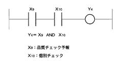
図8は、品質チェック中の稼動状態を出力する稼動状態関数Y4と、各動作状態として、品質チェック予報X9、個別チェック信号X10との関係を図1と同様の表記法で表したものである。図8に示すように、各動作状態をANDで結びつけて、(品質チェック予報有り)かつ(個別チェック中)の状態のときを品質チェック中として算出することができる。
【0064】
すなわち、品質チェック中とは、品質チェック予報が出て、実際に作業者等が品質チェックを行っている稼動状態であるので、品質チェック予報が出ている動作状態では足りない。そこで、2つの動作状態をANDで結びつけて(品質チェック予報あり)かつ(個別チェック)を表す稼動状態関数Y4を構成し、2つの動作状態データを時系列で収集し、これらを稼動状態関数Y4に入力して、品質チェック中稼動状態データを時系列で出力することができる。
【0065】
後工程フル状態算出モジュール160は、ユーザが「後工程フル状態算出」のメニューを指定し、当該工程を特定したときに実行される稼動状態解析処理の機能である。具体的には、当該工程と後工程の動作状態データを取得し、後工程にワークが詰まっているために当該工程に無駄が生じている稼動状態として、後工程フルか否かの稼動状態データを算出する機能を有する。
【0066】
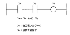
図9は、後工程フル状態の稼動状態を出力する稼動状態関数Y5と、各動作状態として、後工程フルワークX4、当該工程完了X3との関係を図1と同様の表記法で表したものである。図9に示すように、各動作状態をANDで結びつけて、(後工程フルワーク)かつ(当該工程完了)の状態のときを後工程フル状態として算出することができる。
【0067】
すなわち、後工程フル状態とは、当該工程の実作業が完了し、後工程にワークを搬出したいにもかかわらず、後工程にワークが詰まっているために当該工程に無駄が生じている稼動状態であるので、後工程がフルワークだけでは足りず、また、当該工程の実作業が完了していただけでは足りない。そこで、2つの動作状態をANDで結びつけて(後工程フルワーク)かつ(当該工程完了)を表す稼動状態関数Y5を構成し、2つの動作状態データを時系列で収集し、これらを稼動状態関数Y5に入力して、後工程フルの稼動状態データを時系列で出力することができる。
【0068】
前工程空き状態算出モジュール162は、ユーザが「前工程空き状態算出」のメニューを指定し、当該工程を特定したときに実行される稼動状態解析処理の機能である。具体的には、当該工程と前工程の動作状態データを取得し、前工程からワークがこないために当該工程に無駄が生じている稼動状態として、前工程空きか否かの稼動状態データを算出する機能を有する。
【0069】
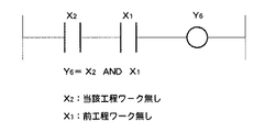
図10は、前工程空き状態の稼動状態を出力する稼動状態関数Y6と、各動作状態として、当該工程ワーク無しX1、前工程ワーク無しX2との関係を図1と同様の表記法で表したものである。図10に示すように、各動作状態をANDで結びつけて、(当該工程ワーク無し)かつ(前工程ワーク無し)の状態のときを前工程空き状態として算出することができる。
【0070】
すなわち、前工程空き状態とは、前工程からワークがこないために当該工程に無駄が生じている稼動状態であるので、前工程にワークが無いだけでは足りず、また、当該工程にワークが無いだけでは足りない。そこで、2つの動作状態をANDで結びつけて(当該工程ワーク無し)かつ(前工程ワーク無し)を表す稼動状態関数Y6を構成し、2つの動作状態データを時系列で収集し、これらを稼動状態関数Y6に入力して、前工程空きの稼動状態データを時系列で出力することができる。
【0071】
上記のように、各工程の稼動状況は、実生産中状態の他、異常停止中等で工程が停止している状態や、後工程フル状態等の無駄状態等の稼動状態で構成される。各工程全体の稼動状況を把握するには、これら複数の稼動状態の占める時間の割合や、その時系列の変化を把握することが好ましい。各工程において、一定期間における各稼動状態の時間割合を示すものとして、いわゆる出来高率が用いられる。この出来高率も、稼動状況関数を用いることで算出することができる。
【0072】
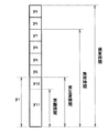
図11は、工程の各稼動状態の時間を積み上げた操業時間の棒グラフである。ここで、出来高率は、全操業時間を1としたときの各稼動状態が占める割合、特に良品を生産する実働時間の割合を表すものである。なお、図11に示すように、出来高率を算出するとともに、全操業時間における稼動状態を分析することができる。例えばその工程に作業の負荷を与えている負荷時間及びその割合、負荷時間の中で実際に部品を生産している実生産時間及びその割合、実生産時間の中で良品を生産する実働時間及びその割合等を求めることができる。
【0073】
図11において、全操業時間と負荷時間との差は、その工程に負荷を与えていない無駄時間で、後工程フル状態の時間y5及び前工程空き状態の時間y6である。したがって、これらは後工程フル状態算出モジュール160及び前工程空き状態算出モジュール162の機能により、それぞれ稼動状態関数Y5=1の状態の時間y5及び稼動状態関数Y6=1の状態の時間y6として求めることができる。
【0074】
負荷時間と実生産時間の差は、その工程が停止している時間で、上記の異常停止状態の時間y2、工具交換状態の時間y3、品質チェック状態の時間y4の他に、段替停止状態の時間y7が含まれる。段替停止状態の時間y7以外は、異常停止中状態算出モジュール154、工具交換状態算出モジュール156、品質チェック状態算出モジュール158の機能により、それぞれ稼動状態関数Y2=1、Y3=1、Y4=1の状態の時間y2,y3,y4として求めることができ、段替停止状態の時間y7は、例えば入力部74からの手入力データを用いることができる。
【0075】
ここで段替停止状態とは、稼動状態の一つで、その工程の作業内容を変更するために工程を停止する状態である。例えば、その工程において午前中はAエンジンの部品を加工していて、午後にBエンジンの部品を加工する場合、ワークを保持する治具やワークを加工する工具、あるいはそれらを集積したハブ等をAエンジン部品用からBエンジン部品用に段取り替えするために要する時間である。通常、段替作業は、安全のためその工程の電源を落として行うことが多い。したがってPLCも一時的に動作を停止し、動作状態データの収集も一時的に停止する。そこで、入力部74から、段替停止状態の作業時間データを段替停止状態の時間データとして手入力で入力し、出来高率算出に用いることができる。もちろん、段替作業の際にもその工程の電源を落とさないものとし、各工程に段替停止スイッチ等を設け、段替作業の際にこの段替停止スイッチを操作し、段替停止信号をPLC経由で稼動状況解析装置に送ることもできる。そして、段替停止状態を示す稼動状態関数を、段替停止信号と連続運転中信号X5等と組み合わせて構成してもよい。
【0076】
実生産時間と実働時間との差は、不良品を生産する時間である。すなわち、実生産時間y1は、良品を生産した実働時間y11と不良品を生産した時間y12とに分けられ、y1=y11+y12である。良品と不良品との判定は、検査工程で行われ、所定期間におけるy11/y1×100%は、いわゆる直行率として別途算出される。そこで、入力部74から、直行率データを手入力で入力し、y11=y1×(直行率)×100%として実働時間y11等を算出し、出来高率算出に用いることができる。
【0077】
このように、段替停止状態データと、直行率データを入力部74から入力することで、稼動状態関数を用いて、各工程において全操業時間に占める各稼動状態の割合、すなわち出来高率を算出することができる。出来高率算出モジュール164は、ユーザが「出来高率算出」のメニューを指定し、当該工程を特定したときに実行される稼動状態解析処理の機能である。具体的には、当該工程とその前後の工程を含む複数の工程における動作状態データと、所定期間における当該工程の段替停止状態時間データと直行率データとを取得し、出来高率を構成する各稼動状態の時間を算出し、それらの間の比率を算出する機能を有する。
【0078】
図11の例では、実生産中状態の割合が50%に満たず、その他の停止状態または無駄状態の各稼動状態がほぼ同じ割合で発生していることが把握できる。なお、上記のように、出来高算出モジュールにおいて、各稼動状態の割合の算出にあわせて、図11に示す実働時間y11、実生産時間y1、負荷時間(y1+y2+y3+y4+y7)等のデータ、あるいはこれらの時間と全操業時間との比率を算出することもできる。
【0079】
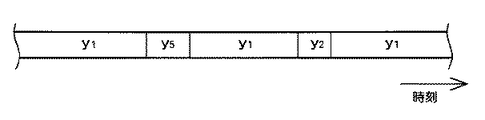
図12は、その工程の稼動状態を時系列で表したものである。すなわち、時々刻々のその工程の稼動状態の変化が、横軸を時刻として表される。かかる工程の時系列の全体稼動状況解析も、解析メニューに追加することができる。
【0080】
アクチュエータ状態算出モジュール166は、ユーザが「アクチュエータ状態算出」のメニューを指定し、対象となる工程の具体的なアクチュエータを特定したときに実行される稼動状態解析処理の機能である。具体的には、対象となるアクチュエータの時系列の動作状態データを取得し、アクチュエータの稼動状態データを算出する機能を有する。
【0081】
例えば、すでに説明した図2は、アクチュエータとしてのシリンダの前進稼動状態及び後退稼動状態を表すものである。上記のように、シリンダの前進稼動状態は、(前進指示有り)かつ(シリンダ前進端が検出されず)を表す稼動状態関数Z1を用いて算出でき、同様にシリンダの後退稼動状態は、(後退指示有り)かつ(シリンダ後退端が検出されず)を表す稼動状態関数Z2を用いて算出できる。シリンダ以外のアクチュエータ、例えばねじ締めヘッド等の稼動状態も同様にして算出することができる。このようにして、稼動状態関数を用いて、特定のアクチュエータの稼動状態データを算出することができる。
【0082】
【発明の効果】
本発明に係る生産ラインの稼動状況解析装置、稼動状況解析方法、稼動状況解析プログラム及び稼動状況解析システムによれば、生産ラインを構成する各工程に専用の回路やプログラムを要せず、各工程の状態を表す信号に基づいて稼動状況を解析できる。本発明に係る生産ラインの稼動状況解析装置、稼動状況解析方法、稼動状況解析プログラム及び稼動状況解析システムによれば、複数の動作状態信号を任意に組み合わせる稼動状態関数を用いて稼動状態を解析できる。本発明に係る生産ラインの稼動状況解析装置、稼動状況解析方法、稼動状況解析プログラム及び稼動状況解析システムによれば、特別な回路やプログラムを要することなく、複数の工程にまたがって稼動状態を解析できる。
【図面の簡単な説明】
【図1】本発明に係る稼動状態関数を説明する図である。
【図2】本発明に係る稼動状態関数を用いて、稼動状態をタイムチャートとして出力する例を示す図である。
【図3】本発明に係る実施の形態における生産ラインの稼動状況解析システムの構成を示すブロック図である。
【図4】本発明に係る実施の形態において、実生産中の稼動状態を出力する稼動状態関数Y1を説明する図である。
【図5】本発明に係る実施の形態において、時系列の各動作状態のデータと、算出された実生産稼動状態のデータの例を示す図である。
【図6】本発明に係る実施の形態において、異常停止中の稼動状態を出力する稼動状態関数Y2を説明する図である。
【図7】本発明に係る実施の形態において、工具交換中の稼動状態を出力する稼動状態関数Y3を説明する図である。
【図8】本発明に係る実施の形態において、品質チェック中の稼動状態を出力する稼動状態関数Y4を説明する図である。
【図9】本発明に係る実施の形態において、後工程フル状態の稼動状態を出力する稼動状態関数Y5を説明する図である。
【図10】本発明に係る実施の形態において、前工程空き状態の稼動状態を出力する稼動状態関数Y6を説明する図である。
【図11】本発明に係る実施の形態において、稼動状態関数を用いて算出された稼動状態データを用い、工程の全体稼動状況として出来高率を示した図である。
【図12】本発明に係る実施の形態において、稼動状態関数を用いて算出された稼動状態データを用い、工程の稼動状態を時系列で表した図である。
【符号の説明】
10 稼動状況解析システム、20 生産設備、22 異常表示装置、30 データ収集装置、50 データ蓄積サーバ、60 稼動状況解析装置、70 CPU、78 外部記憶装置、80 稼動状態関数ファイル、100 データ取得部、150 稼動状態データ算出部、152 実生産中状態算出モジュール、154 異常停止中状態算出モジュール、156 工具交換状態算出モジュール、158 品質チェック状態算出モジュール、160 後工程フル状態算出モジュール、162 前工程空き状態算出モジュール、164 出来高率算出モジュール、166 アクチュエータ状態算出モジュール。[0001]
TECHNICAL FIELD OF THE INVENTION
The present invention relates to an operation status analysis device for a production line, and more particularly to an operation status analysis device that analyzes the operation status of a production line including a plurality of production facilities using data collected by a data collection device.
[0002]
[Prior art]
In order to continuously perform production according to a production plan in a production line including a plurality of processes, it is important to appropriately evaluate the operation state of each process and appropriately evaluate the operation of the entire production line. As means for determining the state of each process, there is a method of recording a signal of a PLC (Programmable Logic Controller) for controlling the operation of equipment constituting each process. However, it is not possible to accurately determine the state of the equipment by simply adding a circuit that outputs a signal indicating the state of each equipment to the PLC program in advance and analyzing the recorded signals independently, so that the regularity of the state transition is used. In this case, the state estimation accuracy is increased. For example, in
[0003]
[Patent Document 1]
JP-A-7-104838
[0004]
[Problems to be solved by the invention]
As described above, adding a circuit that outputs a signal indicating the state of each process to the PLC program requires setting and confirming operation of each process in the field, and also requires checking each process. Since the addresses of the internal signals are different, it is necessary to create a dedicated program for each process facility in order to determine the state, which takes time and costs.
[0005]
Even if a circuit and a program are added for each process as described above, since these are dedicated to each process, the expandability and versatility of the system are poor. For example, since it is difficult to add circuits and programs by extending to multiple processes, it is possible to further advance from the operation status of each process to the overall status of multiple related processes or the operation status of the entire production line. Difficult to grasp.
[0006]
In addition, since the circuits and programs provided in each process are not versatile, the output signals are used only for a dedicated purpose, and a plurality of signals are arbitrarily combined to express different states, etc. It is not possible to grasp the actual operation status.
[0007]
SUMMARY OF THE INVENTION An object of the present invention is to solve the problems of the prior art and eliminate the need for a dedicated circuit or program for each process constituting a production line, and to analyze the operation status based on a signal representing the state of each process. It is an object of the present invention to provide an operation status analysis device, an operation status analysis method, an operation status analysis program, and an operation status analysis system. Another object is to provide a versatile production line operation status analysis device, operation status analysis method, operation status analysis program, and operation status analysis system that can analyze the operation status by arbitrarily combining a plurality of signals. is there. Still another object is to provide a production line operation status analysis device, operation status analysis method, operation status analysis program and operation status analysis system that can analyze the operation status over a plurality of processes without requiring a special circuit or program. To provide. The invention described in the following claims is provided to achieve at least one of the above objects.
[0008]
[Means for Solving the Problems]
1. Operation status function
First, the operating state function will be described. The operation state function is a function configured by connecting a plurality of operation states by an operator. 1 , X 2 , X 3 As X 1 , X 2 , X 3 Are connected by operators such as AND and OR. In one example, Y 0 = [X 1 ORX 2 ] ANDX 3 And so on.
[0009]
Operating state of production equipment, X in the above example 1 , X 2 , X 3 Is obtained by collecting PLC signals. In addition to the operating state, why the operating state function Y 0 Is necessary to calculate a new state because the operating state collected from the PLC or the like cannot often sufficiently represent the operating state that is the dynamic state of the equipment.
[0010]
For example, as one example, the operating state and operating state of one cylinder, which is a work element in a production facility, will be described. Now, if one wants to grasp the operating state that the cylinder is moving forward, the PLC sends the cylinder moving instruction signal X as the operating state of the cylinder. 20 Is collected, and the value is determined to be 1 (forward instruction) or 0 (no forward instruction). By the way, the cylinder advance instruction signal X 20 Is 1, it is not always the case that the cylinder is moving forward. This includes, for example, the case where the cylinder has not yet started moving forward. Therefore, in order to obtain the operating state of forward running, the cylinder forward end detection signal X 21 Must be checked to make sure that the value is 0 (cylinder advance end not detected).
[0011]
In this case, two operating states X 20 , X 21 Can be determined independently to determine whether the cylinder is moving forward. 20 And (NOTX 21 ) Is linked with AND, and this function is referred to as the “in progress” operating state function Z 1 And it is sufficient. "Advancing" operating state function Z 1 Are two operating states X 20 , X 21 Are linked using the operator OR and NOT. Therefore, two operating states X at every moment 20 , X 21 By inputting the data of (1) and (2), it is calculated whether or not the condition is satisfied (there is an advance command) and (the cylinder forward end is not detected). can do.
[0012]
FIG. 1 is an example in which the relationship between the operating state of the cylinder and the operating state of the cylinder is represented by a ladder circuit diagram. Each operation state X 20 , X 21 , X 22 , X 23 Is indicated by a contact symbol, and the operating state function Z 1 , Z 2 Is indicated by a coil symbol. As shown in FIG. 20 And cylinder advance end detection X 21 "In progress" operating state function Z 1 And the cylinder retraction instruction X 22 And cylinder retraction end detection X 23 "Retreating" operating state function Z 2 Can be configured.
[0013]
FIG. 2 shows each operation state X. 20 , X 21 , X 22 , X 23 Is input to the operation state function in a time series, and the “in progress” operation state function Z 1 Output data z 1 And "retreating" operating state function Z 2 Output data z 2 FIG. 9 is a diagram showing an example of outputting a time chart. FIG. 2A shows an operation state of a standard cylinder, and FIG. 2A shows an example in which there is a problem in “retreating”. From these data, it is possible to extract the fact that there is a problem during “retreat” and to perform quantitative analysis such as “forward time” and “retreat time”.
[0014]
As described above, an arbitrary operating state function can be configured by combining a plurality of operating states by an operator. If a plurality of operating state data are input using the operating state function, it is not possible to grasp only the operating state data. The operating state data as a new state can be output.
[0015]
By configuring the function form of the operation state function according to the operation state analysis purpose, desired operation state data can be easily obtained. If a plurality of operation state data is input in a time series, the operation state data in a time series is output, so that more quantitative operation state data can be obtained.
[0016]
A plurality of operating states can be collected from the PLC signal of the production equipment, and the operating state function can be formed into any function form. Can be enhanced. In other words, there is no need to provide a dedicated circuit or a dedicated program for obtaining desired operating state data for each facility. Simply collecting operating state data and inputting the operating state data to the operating state function can provide a desired operating state. Data can be obtained.
[0017]
The operation state function may be a time management function in addition to the logical operation result of the digital data as described above. For example, in the case of FIG. 2, the cylinder retreat time t2 can be determined and output by a threshold function. In this example, if the threshold function is set to 2 sec <t2 <3 sec or the like, 0 can be output as the reverse time operating state data when the reverse time is not within this range.
[0018]
2. Problem solving means
The operation status analysis device according to the present invention is an operation status analysis device that analyzes the operation status of the production line based on operation status data indicating the operation status of each work element of the production line collected by the data collection device, Using a data acquisition means for acquiring a plurality of operation state data collected by the data collection device and an operation state function in which a plurality of operation states are combined by an operator, inputting a plurality of operation state data to the operation state function, Operating state data calculating means for calculating operating state data indicating the operating state of the line.
[0019]
With the above configuration, the operating state function described in “1. Operating state function” is used for calculating the operating state data. As the operation state data input to the operation state function, the operation state data of each work element of the production line is collected by the data collection device. As the operation state data of each work element of the production line, for example, a signal of a PLC provided for each process or a sensor signal can be used as it is. As described above, since the operation state function is composed of the operation state and the operator, an arbitrary function can be created by changing the type of the operation state or the type of the operator. Therefore, the operating state can be analyzed by arbitrarily combining a plurality of signals, and the versatility of the analysis system is high. Also, there is no need for a dedicated circuit or program for outputting a signal indicating the operating state.
[0020]
In addition, the operating state data calculating means inputs operating state data in a plurality of processes including the process and processes before and after the process to an operating state function in order to analyze the operating state of each process of the production line, and as operating state data. It is preferable to calculate process operation state data representing the operation state of each process.
[0021]
The plurality of operation states constituting the operation state function are not limited to only the plurality of operation states in the same process. With the above configuration, the operation state data in a plurality of steps including the step and the preceding and following steps is input to the operation state function, and the step operation state operation data of each step is calculated. The operation status function in this case is configured by combining operation statuses in a plurality of processes by an operator. Therefore, it is possible to analyze the operating state over a plurality of processes without requiring a special circuit or program.
[0022]
In addition, the operating state data calculating means may include, as the operating state of each process, an actual production state indicating actual production, an abnormal stop state indicating abnormal stop, a tool change state indicating tool change, or a quality check. Process operation in one of the following process operation states: a quality check state indicating medium, a post-process full state indicating a waste state in which the post-process work is jammed, or a pre-process empty state indicating a waste state in which there is no work in the previous process. Preferably, state data is calculated.
[0023]
Each process has a plurality of operating states. The operation state of each process can be classified into a plurality of operation states such as an actual production state, an abnormal stop state, a tool change state, a quality check state, a post-process full state, and a pre-process empty state. The operating state of each process can be quantitatively grasped by analyzing the ratio of each of these operating states to the whole. For example, it can be analyzed that a certain process has a high ratio in the actual production state and the operation status is good, and that another process has a high ratio in the abnormal stop state and is a bottleneck process.
[0024]
With the above-described configuration, for at least one of the plurality of process operation states, the operation state data in a plurality of steps including the step and the preceding and following steps is input to the operation state function and calculated. All of the plurality of process operation states may be calculated by an operation state function. By using the operation status function, the process operation status can be calculated only by inputting the operation status data of a plurality of processes including the process concerned and the process before and after, and dedicated to each process for outputting a signal indicating the operation status of the process. There is no need for a specific circuit or program or a special circuit or program that spans the process.
[0025]
Further, the operating state data calculating means may include a plurality of operation state data including the work presence / absence state data in the process, the work presence / absence state data in a process before the process, and the work presence / absence state data in a process after the process. It is preferable to calculate process operation data representing the actual production state of each process based on the process operation data.
[0026]
It is not sufficient to judge the actual production state only by grasping the state in which the work exists in the process. This is because even if there is a work in the process, even if the work is waiting for a full work in the post-process without receiving the actual work such as machining or assembly, This is because the case where the workpiece is made to wait in the previous process is not included. With the above configuration, the actual production state of the process is calculated based on the operation state data of the presence or absence of the work in the process and the processes before and after the process. Therefore, the actual production state data that is correctly obtained by the analysis over a plurality of processes can be calculated without using a special circuit or program.
[0027]
In addition, the operating state data calculating means may determine the full state of the post-process of each step based on a plurality of operation state data including the data indicating whether the work is completed in the relevant step and the data indicating whether the work is present in a subsequent step of the relevant step. It is preferable to calculate the process operation data to be represented.
[0028]
Regarding the full state of the post-process, it is not sufficient to judge that there is no use in the post-process just by grasping the state where the work exists in the post-process of the relevant process. This is because, even if there is a work in the post-process, no wasted time is provided if the process has not yet completed the actual work. With the above configuration, the post-process full state is calculated based on the operation state data in the process and the post-process. Therefore, the post-process full state data correctly obtained by the analysis over a plurality of processes can be calculated without using a special circuit or program.
[0029]
The operating state data calculating means may include a step of representing an empty state of the preceding process of each process based on a plurality of operating state data including the workpiece presence / absence status data in the process and the workpiece presence / absence status data in the preceding process of the process. It is preferable to calculate operation data.
[0030]
Regarding the empty state of the previous process, it is not sufficient to judge that there is no use in the previous process just by grasping the state where there is no work in the previous process of the relevant process. This is because, even if there is no work in the previous process, no wasted time if there is a work in the process. With the above configuration, the previous process empty state is calculated based on the operation state data of the presence or absence of the work in the relevant process and the previous process. Therefore, it is possible to calculate the pre-process empty state data correctly obtained by the analysis over a plurality of processes without using a special circuit or program.
[0031]
Further, the data acquisition unit acquires the operation state data according to the time series, and the operation data calculation unit calculates the operation state data according to the time series based on the acquired operation state data according to the time series. It is preferable to analyze the change over time in the operating state. By analyzing the change over time, the operating state data can be grasped more quantitatively. In addition, time-series analysis of the operating state can be performed without requiring a dedicated circuit and program.
[0032]
Further, an operation status analysis method according to the present invention is an operation status analysis method for analyzing the operation status of a production line based on operation status data indicating the operation status of each work element of a production line collected by a data collection device. Inputting a plurality of operation state data to the operation state function using a data acquisition step of acquiring a plurality of operation state data collected by the data collection device and an operation state function in which the plurality of operation states are combined by an operator; Operating state data calculating step of calculating operating state data representing the operating state of the production line.
[0033]
The operating condition analysis program according to the present invention is an operating condition analyzing program for analyzing the operating condition of a production line based on operating condition data indicating the operating condition of each work element of a production line collected by a data collecting device. The operation status analysis device uses a data acquisition processing procedure for acquiring a plurality of operation status data collected by the data collection device, and an operation status function in which a plurality of operation statuses are combined by an operator, and generates a plurality of operation status data. Is input to the operating state function, and an operating state data calculating process for calculating operating state data representing the operating state of the production line is executed.
[0034]
Further, the operation status analysis system according to the present invention is provided for each process of the production line, a plurality of data collection devices that collect and output operation state data representing the operation state of each work element constituting the production line, A data storage server that receives and outputs data output from each data collection device, and obtains a plurality of operation state data from the data storage server, and uses an operation state function in which a plurality of operation states are combined by an operator, An operation status analysis device that calculates operation status data representing the operation status of the production line by inputting a plurality of acquired operation status data to the operation status function.
[0035]
With the above configuration, the operation state data of each work element constituting the production line is collected by a data collection device provided in each step. The data collection device collects, as operation state data of each work element, for example, data of a plurality of control elements for controlling the operation of production equipment constituting each process, data of signals of various sensors, and the like. Then, the data collected by the data collection device is stored by the data storage server. Therefore, since the operation state data arranged in each process unit is stored by the data storage server, the load on the data storage server is reduced. For example, in each process, every time the processing on the work is completed, the operation state data can be sent to the data storage server in a lump, and data storage with good division can be performed with a small load. Further, even if the configuration of the production line changes, it is divided in process units, so that the data collection system can have flexibility.
[0036]
BEST MODE FOR CARRYING OUT THE INVENTION
Hereinafter, embodiments of the present invention will be described in detail with reference to the drawings. In the following, a part production line for producing engine parts for vehicles will be described as an example. However, as long as the production line is a production line including a plurality of production facilities or processes, a production line other than the engine part production line is used. There may be. For example, a production line for parts other than engine parts, an assembly line, an inspection line, and the like may be used, and the invention is not limited to a production line for vehicles.
[0037]
FIG. 3 is a block diagram illustrating a configuration of the operation
[0038]
Each
[0039]
Each
[0040]
Each production facility is provided with a
[0041]
The operation state data representing these operation states corresponds to the operation state of each of a plurality of work elements in one
[0042]
The
[0043]
The lighting of the
[0044]
The
[0045]
The
[0046]
The
[0047]
The
[0048]
The operation
[0049]
The operation
[0050]
The
[0051]
The operation state
[0052]
The actual production
[0053]
FIG. 4 shows an operation state function Y that outputs an operation state during actual production. 1 , Using the same symbols as those shown in FIG. 1 No work in front process X 2 , The process completion X 3 , Post-process full work X 4 , X during continuous operation 5 It shows the relationship with. As shown in FIG. 4, the respective operation states are linked by AND, OR, and NOT, and the states of (there is a work in the previous process) and (the work in the previous process) and the state of (the work has not been completed) and (the work is not a full work in the post process). )) And an operating state function Y representing the state of (during continuous operation) 1 Can be used to calculate during actual production.
[0054]
In other words, the “in actual production” is an operation state in which actual work is being performed without waste, so that (during continuous operation) is not sufficient, and (actual process work is present) and (pre-process work is present) and It is necessary that there be no waste in relation to the process or that (the process is not completed) and (the post-process is not full work) and there is no waste in relation to the post-process. To grasp the operating state during actual production, it is necessary to monitor five operating state data. 1 Is used, five operation state data are collected in time series, and these are collected into an operation state function Y 1 , The operating state data during actual production can be output in chronological order. FIG. 5 shows each operation state X in the time series. 1 , X 2 , X 3 , X 4 , X 5 Data and the operating state function Y during actual production 1 Here is an example of output data.
[0055]
The abnormally stopped
[0056]
FIG. 6 shows an operation state function Y for outputting an operation state during abnormal stop. 2 And X as the operating state during continuous operation. 5 , Abnormal signal X 6 Is expressed in the same notation as in FIG. As shown in FIG. 6, by linking the operation states with AND, it is possible to calculate the state of (not continuous operation) and the state of (abnormal) as abnormal stop.
[0057]
That is, the abnormal stop is an operation state in which the process is stopped due to an abnormality, and therefore, the operation state in which an abnormal signal is output is not sufficient, and the operation state in which the process is stopped is not sufficient. . Therefore, the operation state function Y which connects the two operation states by AND (not in continuous operation) and represents (abnormal) 2 And collects two operation state data in a time series, and collects these data into an operation state function Y 2 To output the operating state data during abnormal stop in a time series.
[0058]
The tool change
[0059]
FIG. 7 shows an operation state function Y for outputting an operation state during tool change. 3 And tool change forecast X as each operation state 7 , Individual exchange signal X 8 Is expressed in the same notation as in FIG. As shown in FIG. 7, by linking the respective operation states by AND, it is possible to calculate that the state of (there is a tool change forecast) and the state of (individually changing) are being changed.
[0060]
That is, during the tool change, the tool change forecast is issued, and the operation state is such that the operator or the like is actually performing the tool change. Therefore, the operation state in which the tool change forecast is issued is not sufficient. Therefore, an operation state function Y representing two operation states linked by AND (with tool change forecast) and (individual change) 3 And collects two operation state data in a time series, and collects these data into an operation state function Y 3 To output the operating state data during tool change in chronological order.
[0061]
The quality check
[0062]
In a production line, a process may be stopped in order to perform a quality check on whether a work is processed or assembled according to production specifications. For example, when a sampling quality check is performed for one workpiece per 100 pieces, a quality check forecast is issued at the same time as the sampling is performed, and in accordance with the forecast, an operator or the like goes to the process where the forecast is issued. Then, the process is suspended and the quality of the work is checked. Therefore, whether or not the process is under quality check is one of the operation status data indicating the operation status of the process.
[0063]
FIG. 8 shows an operation state function Y for outputting an operation state during quality check. 4 And the quality check forecast X as each operation state 9 , Individual check signal X 10 Is expressed in the same notation as in FIG. As shown in FIG. 8, by linking the respective operation states by AND, it is possible to calculate that the state of (with quality check forecast) and the state of (individual check) is under quality check.
[0064]
That is, the quality check is being performed, which means that the quality check forecast is issued and the operation state in which the worker or the like is actually performing the quality check is not sufficient in the operation state in which the quality check forecast is issued. Therefore, an operation state function Y representing two operation states linked by AND (with quality check forecast) and (individual check) 4 And collects two operation state data in a time series, and collects these data into an operation state function Y 4 To output the operating state data during the quality check in time series.
[0065]
The post-process full
[0066]
FIG. 9 shows an operation state function Y that outputs the operation state of the post-process full state. 5 And the post-process full work X 4 , The process completion X 3 Is expressed in the same notation as in FIG. As shown in FIG. 9, the respective operation states are linked by AND, and the state of (post-process full work) and (the relevant process is completed) can be calculated as the post-process full state.
[0067]
That is, the post-process full state is an operation state in which the actual work of the process is completed and the work is clogged in the post-process, but the process is wasted even though the work is to be carried out to the post-process. Therefore, it is not enough for the post-process to be performed only by the full work, and it is not sufficient to complete the actual work of the process. Therefore, an operation state function Y that connects two operation states with AND (post-process full work) and (completes the process) 5 And collects two operation state data in a time series, and collects these data into an operation state function Y 5 , And the operation status data of the full post-process can be output in chronological order.
[0068]
The pre-process empty
[0069]
FIG. 10 shows an operation state function Y that outputs the operation state of the empty state of the previous process. 6 , And each operation state, there is no process work X 1 No work in front process X 2 Is expressed in the same notation as in FIG. As shown in FIG. 10, each operation state is linked by AND, and the state of (there is no process work) and the state of (there is no work in the previous process) can be calculated as the empty state in the previous process.
[0070]
That is, the empty state in the previous process is an operation state in which the process is wasted because the work does not come from the previous process. Therefore, it is not sufficient that there is no work in the previous process, and there is no work in the process. Is not enough. Therefore, an operating state function Y representing two operating states connected by AND (without the process work concerned) and (without the preceding process work) 6 And collects two operation state data in a time series, and collects these data into an operation state function Y 6 To output the operation state data of the empty space in the previous process in chronological order.
[0071]
As described above, the operation status of each process includes an operation status such as a status where the process is stopped due to abnormal stop or the like and a waste status such as a full status of the post-process, in addition to the status of actual production. In order to ascertain the operation status of each process as a whole, it is preferable to ascertain the ratio of the time occupied by the plurality of operation states and the change in the time series. In each process, a so-called output rate is used as a value indicating a time ratio of each operation state in a certain period. This volume rate can also be calculated by using the operation status function.
[0072]
FIG. 11 is a bar graph of the operation time obtained by accumulating the time of each operation state of the process. Here, the yield rate represents the ratio of each operation state when the total operation time is 1, particularly the ratio of the actual operation time for producing non-defective products. In addition, as shown in FIG. 11, it is possible to calculate the yield rate and analyze the operating state during the entire operation time. For example, the load time and the ratio that gives the work load to the process, the actual production time and the ratio of actually producing parts during the load time, the actual working time and the actual production time that produce a good product in the actual production time The ratio and the like can be obtained.
[0073]
In FIG. 11, the difference between the total operation time and the load time is the dead time in which no load is applied to the process, and the time y in the post-process full state is shown. 5 And the time y in which the previous process is empty 6 It is. Therefore, these are operated by the functions of the post-process full
[0074]
The difference between the load time and the actual production time is the time during which the process is stopped, and the time y during the abnormal stop state. 2 , Tool change time y 3 , Quality check status time y 4 In addition, the time y during which the change 7 Is included. Time y during which changeover is stopped 7 Other than the above, the operation state function Y 2 = 1, Y 3 = 1, Y 4 = 1 time y 2 , Y 3 , Y 4 And the time y during which the change is stopped 7 For example, manual input data from the
[0075]
Here, the change stop state is one of the operating states, and is a state in which the process is stopped in order to change the work content of the process. For example, in the process, when processing parts of the engine A in the morning and processing parts of the engine B in the afternoon, a jig for holding the work, a tool for processing the work, or a hub or the like in which these are integrated. This is the time required to change the setup from engine A parts to engine B parts. Normally, the changeover operation is often performed with the power supply of the process turned off for safety. Therefore, the operation of the PLC also temporarily stops, and the collection of the operation state data also temporarily stops. Therefore, the work time data in the stoppage state of the shift stop can be manually input as the time data of the stop state in the stoppage from the
[0076]
The difference between the actual production time and the actual working time is the time for producing defective products. That is, the actual production time y 1 Is the actual working time y that produced a good product 11 And the time of production of defective products y 12 And y 1 = Y 11 + Y 12 It is. The determination of a good product or a defective product is performed in an inspection process, and y is determined in a predetermined period. 11 / Y 1 × 100% is separately calculated as a so-called orthogonality ratio. Therefore, the traverse rate data is manually input from the
[0077]
As described above, by inputting the change stop state data and the traverse rate data from the
[0078]
In the example of FIG. 11, it can be understood that the ratio of the actual production state is less than 50%, and the other operation states of the stopped state or the waste state occur at substantially the same rate. Note that, as described above, in the yield calculation module, the actual working time y shown in FIG. 11 , Actual production time y 1 , Load time (y 1 + Y 2 + Y 3 + Y 4 + Y 7 ), Or the ratio of these times to the total operating time can also be calculated.
[0079]
FIG. 12 shows the operation state of the process in a time series. That is, the change of the operation state of the process every moment is represented by time on the horizontal axis. The analysis of the overall operation status in the time series of such a process can also be added to the analysis menu.
[0080]
The actuator
[0081]
For example, FIG. 2 described above shows a forward operating state and a backward operating state of a cylinder as an actuator. As described above, the forward operation state of the cylinder is represented by an operation state function Z representing (forward instruction is present) and (cylinder forward end is not detected). 1 Similarly, the cylinder retreat operating state is represented by an operating state function Z representing (with a retraction instruction) and (no cylinder retraction end detected). 2 Can be calculated using The operating state of an actuator other than the cylinder, for example, a screwing head can be calculated in the same manner. In this way, the operating state data of a specific actuator can be calculated using the operating state function.
[0082]
【The invention's effect】
According to the production line operation status analysis apparatus, operation status analysis method, operation status analysis program, and operation status analysis system of the present invention, each process constituting the production line does not require a dedicated circuit or program, and each process The operation status can be analyzed based on the signal indicating the status of the operation. ADVANTAGE OF THE INVENTION According to the operation condition analysis apparatus of a production line, the operation condition analysis method, the operation condition analysis program, and the operation condition analysis system which concern on this invention, an operation condition can be analyzed using the operation condition function which arbitrarily combines several operation condition signals. . According to the operation condition analysis device, operation condition analysis method, operation condition analysis program, and operation condition analysis system of the production line according to the present invention, the operation condition is analyzed over a plurality of processes without requiring a special circuit or program. it can.
[Brief description of the drawings]
FIG. 1 is a diagram illustrating an operation state function according to the present invention.
FIG. 2 is a diagram illustrating an example of outputting an operation state as a time chart using the operation state function according to the present invention.
FIG. 3 is a block diagram showing a configuration of an operation status analysis system of a production line in the embodiment according to the present invention.
FIG. 4 shows an operation state function Y for outputting an operation state during actual production in the embodiment according to the present invention. 1 FIG.
FIG. 5 is a diagram showing an example of time-series data of each operation state and data of a calculated actual production operation state in the embodiment according to the present invention.
FIG. 6 is a diagram illustrating an operation state function Y for outputting an operation state during abnormal stop in the embodiment according to the present invention. 2 FIG.
FIG. 7 shows an operation state function Y for outputting an operation state during tool change in the embodiment according to the present invention. 3 FIG.
FIG. 8 is a diagram illustrating an operation state function Y that outputs an operation state during quality check in the embodiment according to the present invention. 4 FIG.
FIG. 9 is a diagram illustrating an operation state function Y that outputs an operation state of a post-process full state in the embodiment according to the present invention. 5 FIG.
FIG. 10 is a diagram illustrating an operation state function Y that outputs an operation state of a pre-process empty state in the embodiment according to the present invention. 6 FIG.
FIG. 11 is a diagram showing a yield rate as an overall operation state of a process using operation state data calculated using an operation state function in the embodiment according to the present invention.
FIG. 12 is a diagram showing, in the embodiment according to the present invention, operating states of processes in a time series using operating state data calculated using an operating state function.
[Explanation of symbols]
10 operation status analysis system, 20 production equipment, 22 abnormality display device, 30 data collection device, 50 data storage server, 60 operation status analysis device, 70 CPU, 78 external storage device, 80 operation status function file, 100 data acquisition unit, 150 operation state data calculation unit, 152 actual production state calculation module, 154 abnormal stop state calculation module, 156 tool change state calculation module, 158 quality check state calculation module, 160 post-process full state calculation module, 162 pre-process empty state Calculation module, 164 Output rate calculation module, 166 Actuator state calculation module.
Claims (10)
データ収集装置により収集された複数の動作状態データを取得するデータ取得手段と、
複数の動作状態を演算子によって組み合わせた稼動状態関数を用い、複数の動作状態データを稼動状態関数に入力し、生産ラインの稼動状態を表す稼動状態データを算出する稼動状態データ算出手段と、
を備えることを特徴とする稼動状況解析装置。An operation status analysis device that analyzes the operation status of the production line based on operation status data representing the operation status of each work element of the production line collected by the data collection device,
Data acquisition means for acquiring a plurality of operation state data collected by the data collection device,
An operating state data calculating unit that uses an operating state function in which a plurality of operating states are combined by an operator, inputs a plurality of operating state data to the operating state function, and calculates operating state data representing the operating state of the production line,
An operation status analysis device, comprising:
稼動状態データ算出手段は、生産ラインの各工程の稼動状態を解析するため、当該工程とその前後の工程を含む複数の工程における動作状態データを稼動状態関数に入力し、稼動状態データとして、各工程の稼動状態を表す工程稼動状態データを算出することを特徴とする稼動状況解析装置。The operation status analysis device according to claim 1,
The operating state data calculating means inputs operating state data in a plurality of processes including the process and the processes before and after the process to an operating state function in order to analyze the operating state of each process of the production line, and as operating state data, An operation status analysis apparatus for calculating process operation status data representing an operation status of a process.
稼働状態データ算出手段は、各工程の稼動状態として、実生産中を表す実生産中状態、または異常停止中を表す異常停止中状態、または工具交換中を表す工具交換状態、または品質チェック中を表す品質チェック状態、または後工程ワークが詰まっているむだ状態を表す後工程フル状態、または前工程にワークがないむだ状態を表す前工程空き状態のいずれか1の工程稼動状態について工程稼動状態データを算出することを特徴とする稼動状況解析装置。The operation status analysis device according to claim 2,
The operating state data calculating means, as the operating state of each process, the actual production state indicating the actual production, the abnormal stop state indicating the abnormal stop, the tool change state indicating the tool change, or the quality check Process operation state data for any one of the following process operation states: a quality check state, a full state in the post-process indicating a waste state in which the post-process work is clogged, or an empty state in the previous process indicating a waste state in which no work is present in the previous process An operating condition analysis apparatus characterized by calculating the following.
稼働状態データ算出手段は、
当該工程におけるワーク有無状態データと、
当該工程の前工程におけるワーク有無状態データと、
当該工程の後工程におけるワーク有無状態データと、
を含む複数の動作状態データに基づいて各工程の実生産中状態を表す工程稼動データを算出することを特徴とする稼動状況解析装置。The operation status analysis device according to claim 3,
The operating state data calculating means includes:
Work presence / absence state data in the process,
Work presence / absence state data in the process before the process,
Work presence / absence state data in the post-process of the process,
An operation status analysis apparatus which calculates process operation data representing an actual production state of each process based on a plurality of operation state data including:
稼働状態データ算出手段は、
当該工程における作業完了の有無状態データと、
当該工程の後工程におけるワーク有無状態データと、
を含む複数の動作状態データに基づいて各工程の後工程フル状態を表す工程稼動データを算出することを特徴とする稼動状況解析装置。The operation status analysis device according to claim 3,
The operating state data calculating means includes:
Work completion status data in the process,
Work presence / absence state data in the post-process of the process,
An operation status analysis apparatus that calculates process operation data representing a post-process full state of each process based on a plurality of operation state data including:
稼働状態データ算出手段は、
当該工程におけるワーク有無状態データと、
当該工程の前工程におけるワーク有無状態データと、
を含む複数の動作状態データに基づいて各工程の前工程空き状態を表す工程稼動データを算出することを特徴とする稼動状況解析装置。The operation status analysis device according to claim 3,
The operating state data calculating means includes:
Work presence / absence state data in the process,
Work presence / absence state data in the process before the process,
An operation status analysis apparatus, which calculates process operation data indicating an empty state of a previous process of each process based on a plurality of operation state data including:
データ取得手段は、時系列に従った動作状態データを取得し、
稼働データ算出手段は、取得された時系列に従った動作状態データに基づき、時系列に従った稼動状態データを算出し、稼動状態の経時変化を解析することを特徴とする稼動状況解析装置。The operation status analysis device according to claim 1,
The data acquisition means acquires operation state data according to a time series,
The operation data analysis means calculates the operation data according to the time series based on the acquired operation data according to the time series, and analyzes the change with time of the operation state.
データ収集装置により収集された複数の動作状態データを取得するデータ取得ステップと、
複数の動作状態を演算子によって組み合わせた稼動状態関数を用い、複数の動作状態データを稼動状態関数に入力し、生産ラインの稼動状態を表す稼動状態データを算出する稼動状態データ算出ステップと、
を備えることを特徴とする稼動状況解析方法。An operation status analysis method for analyzing an operation status of a production line based on operation status data representing an operation status of each work element of a production line collected by a data collection device,
A data acquisition step of acquiring a plurality of operation state data collected by the data collection device,
An operating state data calculating step of inputting a plurality of operating state data to the operating state function using an operating state function in which a plurality of operating states are combined by an operator, and calculating operating state data representing the operating state of the production line,
An operation status analysis method, comprising:
稼動状況解析装置に、
データ収集装置により収集された複数の動作状態データを取得するデータ取得処理手順と、
複数の動作状態を演算子によって組み合わせた稼動状態関数を用い、複数の動作状態データを稼動状態関数に入力し、生産ラインの稼動状態を表す稼動状態データを算出する稼動状態データ算出処理手順と、
を実行させることを特徴とする稼動状況解析プログラム。An operation status analysis program for analyzing the operation status of the production line based on operation status data representing the operation status of each work element of the production line collected by the data collection device,
The operation status analyzer
A data acquisition processing procedure for acquiring a plurality of operation state data collected by the data collection device,
An operating state data calculation processing procedure for inputting a plurality of operating state data to the operating state function and calculating operating state data representing the operating state of the production line, using an operating state function in which a plurality of operating states are combined by an operator,
An operation status analysis program characterized by causing a computer to execute.
各データ収集装置から出力されるデータを受け取り、蓄積するデータ蓄積サーバと、
データ蓄積サーバから、複数の動作状態データを取得し、複数の動作状態を演算子によって組み合わせた稼動状態関数を用い、取得した複数の動作状態データを稼動状態関数に入力することで、生産ラインの稼動状態を表す稼動状態データを算出する稼動状況解析装置と、
を含むことを特徴とする稼動状況解析システム。A plurality of data collection devices that are provided for each process of the production line and collect and output operation state data representing the operation state of each work element constituting the production line;
A data storage server for receiving and storing data output from each data collection device;
By acquiring a plurality of operation state data from the data storage server, using an operation state function obtained by combining a plurality of operation states with an operator, and inputting the acquired plurality of operation state data to the operation state function, the production line An operation state analysis device that calculates operation state data representing the operation state;
An operation status analysis system characterized by including:
Priority Applications (1)
| Application Number | Priority Date | Filing Date | Title |
|---|---|---|---|
| JP2003076718A JP4348975B2 (en) | 2003-03-20 | 2003-03-20 | Production line operating status analysis device, operating status analysis method, operating status analysis program, and operating status analysis system |
Applications Claiming Priority (1)
| Application Number | Priority Date | Filing Date | Title |
|---|---|---|---|
| JP2003076718A JP4348975B2 (en) | 2003-03-20 | 2003-03-20 | Production line operating status analysis device, operating status analysis method, operating status analysis program, and operating status analysis system |
Publications (2)
| Publication Number | Publication Date |
|---|---|
| JP2004287635A true JP2004287635A (en) | 2004-10-14 |
| JP4348975B2 JP4348975B2 (en) | 2009-10-21 |
Family
ID=33291656
Family Applications (1)
| Application Number | Title | Priority Date | Filing Date |
|---|---|---|---|
| JP2003076718A Expired - Fee Related JP4348975B2 (en) | 2003-03-20 | 2003-03-20 | Production line operating status analysis device, operating status analysis method, operating status analysis program, and operating status analysis system |
Country Status (1)
| Country | Link |
|---|---|
| JP (1) | JP4348975B2 (en) |
Cited By (11)
| Publication number | Priority date | Publication date | Assignee | Title |
|---|---|---|---|---|
| JP2008090351A (en) * | 2006-09-29 | 2008-04-17 | Omron Corp | Work record analysis apparatus, work record analysis method, program, and recording medium |
| JP2008097128A (en) * | 2006-10-06 | 2008-04-24 | Cimx Kk | Management apparatus, analysis apparatus and program |
| JP2010528379A (en) * | 2007-05-29 | 2010-08-19 | コモンウェルス サイエンティフィック アンド インダストリアル リサーチ オーガニゼイション | Monitoring method and monitoring device |
| JP2011233154A (en) * | 2011-06-14 | 2011-11-17 | Omron Corp | Data collection system, analysis device, analysis method and program |
| JP2016106325A (en) * | 2016-02-29 | 2016-06-16 | 昭和精機株式会社 | Utilization state analysis device and method |
| EP1783569A3 (en) * | 2005-10-21 | 2016-10-12 | Omron Corporation | Data collection system |
| JP2017208072A (en) * | 2016-05-13 | 2017-11-24 | 株式会社リコー | Information processing apparatus, information processing method, information processing program, and information processing system |
| JP2018010430A (en) * | 2016-07-12 | 2018-01-18 | 富士電機株式会社 | Device and system for remote monitoring of control system |
| WO2021074994A1 (en) * | 2019-10-16 | 2021-04-22 | 株式会社Fuji | Machine tool |
| CN114690724A (en) * | 2022-03-31 | 2022-07-01 | 欧姆龙(上海)有限公司 | Industrial production monitoring device and method |
| JPWO2024194916A1 (en) * | 2023-03-17 | 2024-09-26 |
Families Citing this family (1)
| Publication number | Priority date | Publication date | Assignee | Title |
|---|---|---|---|---|
| CN107984471B (en) * | 2016-10-26 | 2020-08-11 | 珠海格力智能装备有限公司 | Method and device for determining working state of robot and robot |
Citations (6)
| Publication number | Priority date | Publication date | Assignee | Title |
|---|---|---|---|---|
| JPH023094A (en) * | 1988-06-17 | 1990-01-08 | Fujitsu Ltd | State displaying method for system containing plural apparatuses |
| JPH05189026A (en) * | 1991-06-25 | 1993-07-30 | Matsushita Electric Works Ltd | Facility fault diagnostic method |
| JPH07104838A (en) * | 1993-10-08 | 1995-04-21 | Mazda Motor Corp | Operation management system |
| JPH08221117A (en) * | 1995-02-09 | 1996-08-30 | Mitsubishi Electric Corp | Analysis device for abnormality diagnosis support |
| JP2000141182A (en) * | 1998-11-13 | 2000-05-23 | Misawa Homes Co Ltd | Work machining device and manufacturing system |
| JP2003050618A (en) * | 2001-08-06 | 2003-02-21 | Hitachi Ltd | Process device management method and process device management device |
-
2003
- 2003-03-20 JP JP2003076718A patent/JP4348975B2/en not_active Expired - Fee Related
Patent Citations (6)
| Publication number | Priority date | Publication date | Assignee | Title |
|---|---|---|---|---|
| JPH023094A (en) * | 1988-06-17 | 1990-01-08 | Fujitsu Ltd | State displaying method for system containing plural apparatuses |
| JPH05189026A (en) * | 1991-06-25 | 1993-07-30 | Matsushita Electric Works Ltd | Facility fault diagnostic method |
| JPH07104838A (en) * | 1993-10-08 | 1995-04-21 | Mazda Motor Corp | Operation management system |
| JPH08221117A (en) * | 1995-02-09 | 1996-08-30 | Mitsubishi Electric Corp | Analysis device for abnormality diagnosis support |
| JP2000141182A (en) * | 1998-11-13 | 2000-05-23 | Misawa Homes Co Ltd | Work machining device and manufacturing system |
| JP2003050618A (en) * | 2001-08-06 | 2003-02-21 | Hitachi Ltd | Process device management method and process device management device |
Cited By (16)
| Publication number | Priority date | Publication date | Assignee | Title |
|---|---|---|---|---|
| EP1783569A3 (en) * | 2005-10-21 | 2016-10-12 | Omron Corporation | Data collection system |
| JP2008090351A (en) * | 2006-09-29 | 2008-04-17 | Omron Corp | Work record analysis apparatus, work record analysis method, program, and recording medium |
| JP2008097128A (en) * | 2006-10-06 | 2008-04-24 | Cimx Kk | Management apparatus, analysis apparatus and program |
| JP2010528379A (en) * | 2007-05-29 | 2010-08-19 | コモンウェルス サイエンティフィック アンド インダストリアル リサーチ オーガニゼイション | Monitoring method and monitoring device |
| JP2011233154A (en) * | 2011-06-14 | 2011-11-17 | Omron Corp | Data collection system, analysis device, analysis method and program |
| JP2016106325A (en) * | 2016-02-29 | 2016-06-16 | 昭和精機株式会社 | Utilization state analysis device and method |
| JP7131646B2 (en) | 2016-05-13 | 2022-09-06 | 株式会社リコー | Information processing device, information processing method, information processing program, and information processing system |
| JP2021096882A (en) * | 2016-05-13 | 2021-06-24 | 株式会社リコー | Information processing device, information processing method, information processing program and information processing system |
| JP2017208072A (en) * | 2016-05-13 | 2017-11-24 | 株式会社リコー | Information processing apparatus, information processing method, information processing program, and information processing system |
| JP2018010430A (en) * | 2016-07-12 | 2018-01-18 | 富士電機株式会社 | Device and system for remote monitoring of control system |
| WO2021074994A1 (en) * | 2019-10-16 | 2021-04-22 | 株式会社Fuji | Machine tool |
| JPWO2021074994A1 (en) * | 2019-10-16 | 2021-04-22 | ||
| JP7198569B2 (en) | 2019-10-16 | 2023-01-04 | 株式会社Fuji | Machine Tools |
| CN114690724A (en) * | 2022-03-31 | 2022-07-01 | 欧姆龙(上海)有限公司 | Industrial production monitoring device and method |
| JPWO2024194916A1 (en) * | 2023-03-17 | 2024-09-26 | ||
| WO2024194916A1 (en) * | 2023-03-17 | 2024-09-26 | 三菱電機株式会社 | Program, data selection device, data analysis system, and data selection method |
Also Published As
| Publication number | Publication date |
|---|---|
| JP4348975B2 (en) | 2009-10-21 |
Similar Documents
| Publication | Publication Date | Title |
|---|---|---|
| JP4556380B2 (en) | Production line operating status analysis device, operating status analysis method, operating status analysis program, and operating status analysis system | |
| JP4348975B2 (en) | Production line operating status analysis device, operating status analysis method, operating status analysis program, and operating status analysis system | |
| US7684892B2 (en) | Process for generating control sequence of operations | |
| US7809457B2 (en) | Framework for automatic generation of sequence of operations | |
| US7069185B1 (en) | Computerized machine controller diagnostic system | |
| US20080078811A1 (en) | Weld data acquisition | |
| CN111007808A (en) | Workshop production monitoring system and method | |
| JPH09330114A (en) | Device and method for abnormality diagnosis of processing facility | |
| US6459958B1 (en) | Operation data display device for robot | |
| CN112859740A (en) | Data acquisition device of numerical control machine tool | |
| JP2002078200A (en) | Monitoring control device and storage medium | |
| CN111458592A (en) | Auto Lamp Drive Module Automatic Detection System | |
| CN100527027C (en) | Assembly line operation status analysis system and analysis method thereof | |
| CN114281052A (en) | Device, system and method for monitoring operating state of mechanical equipment | |
| JP5312475B2 (en) | Method for analyzing energy consumption of mechanical device and mechanical device | |
| CN101403894A (en) | Status indication method and status indication system | |
| JP3193120B2 (en) | Tool abnormality detection device | |
| JP2010134888A (en) | Method and system for monitoring equipment operation | |
| CN201788390U (en) | Andon system for numerical control drilling machine | |
| CN119044087A (en) | Automatic detection method and system for material containing elements | |
| JP2022158229A (en) | Programmable logic controller system | |
| KR20170081383A (en) | Visualization apparatus for manufacturing execution, and method applied to the same | |
| JP2022002044A (en) | Facility state analyzer | |
| JP2009123135A (en) | Robot operation state grasping system and method | |
| JP3666422B2 (en) | Data monitoring device |
Legal Events
| Date | Code | Title | Description |
|---|---|---|---|
| A621 | Written request for application examination |
Free format text: JAPANESE INTERMEDIATE CODE: A621 Effective date: 20051021 |
|
| A977 | Report on retrieval |
Free format text: JAPANESE INTERMEDIATE CODE: A971007 Effective date: 20080625 |
|
| A131 | Notification of reasons for refusal |
Free format text: JAPANESE INTERMEDIATE CODE: A131 Effective date: 20080708 |
|
| A521 | Written amendment |
Free format text: JAPANESE INTERMEDIATE CODE: A523 Effective date: 20080828 |
|
| A131 | Notification of reasons for refusal |
Free format text: JAPANESE INTERMEDIATE CODE: A131 Effective date: 20081021 |
|
| A521 | Written amendment |
Free format text: JAPANESE INTERMEDIATE CODE: A523 Effective date: 20081222 |
|
| A02 | Decision of refusal |
Free format text: JAPANESE INTERMEDIATE CODE: A02 Effective date: 20090210 |
|
| A521 | Written amendment |
Free format text: JAPANESE INTERMEDIATE CODE: A523 Effective date: 20090407 |
|
| A911 | Transfer of reconsideration by examiner before appeal (zenchi) |
Free format text: JAPANESE INTERMEDIATE CODE: A911 Effective date: 20090417 |
|
| TRDD | Decision of grant or rejection written | ||
| A01 | Written decision to grant a patent or to grant a registration (utility model) |
Free format text: JAPANESE INTERMEDIATE CODE: A01 Effective date: 20090630 |
|
| A01 | Written decision to grant a patent or to grant a registration (utility model) |
Free format text: JAPANESE INTERMEDIATE CODE: A01 |
|
| A61 | First payment of annual fees (during grant procedure) |
Free format text: JAPANESE INTERMEDIATE CODE: A61 Effective date: 20090713 |
|
| FPAY | Renewal fee payment (event date is renewal date of database) |
Free format text: PAYMENT UNTIL: 20120731 Year of fee payment: 3 |
|
| R151 | Written notification of patent or utility model registration |
Ref document number: 4348975 Country of ref document: JP Free format text: JAPANESE INTERMEDIATE CODE: R151 |
|
| FPAY | Renewal fee payment (event date is renewal date of database) |
Free format text: PAYMENT UNTIL: 20130731 Year of fee payment: 4 |
|
| LAPS | Cancellation because of no payment of annual fees |