JP2004299727A - Dispenser container - Google Patents
Dispenser container Download PDFInfo
- Publication number
- JP2004299727A JP2004299727A JP2003094032A JP2003094032A JP2004299727A JP 2004299727 A JP2004299727 A JP 2004299727A JP 2003094032 A JP2003094032 A JP 2003094032A JP 2003094032 A JP2003094032 A JP 2003094032A JP 2004299727 A JP2004299727 A JP 2004299727A
- Authority
- JP
- Japan
- Prior art keywords
- liquid
- plunger
- content
- contents
- cylinder
- Prior art date
- Legal status (The legal status is an assumption and is not a legal conclusion. Google has not performed a legal analysis and makes no representation as to the accuracy of the status listed.)
- Withdrawn
Links
Images
Classifications
-
- B—PERFORMING OPERATIONS; TRANSPORTING
- B05—SPRAYING OR ATOMISING IN GENERAL; APPLYING FLUENT MATERIALS TO SURFACES, IN GENERAL
- B05B—SPRAYING APPARATUS; ATOMISING APPARATUS; NOZZLES
- B05B11/00—Single-unit hand-held apparatus in which flow of contents is produced by the muscular force of the operator at the moment of use
- B05B11/01—Single-unit hand-held apparatus in which flow of contents is produced by the muscular force of the operator at the moment of use characterised by the means producing the flow
- B05B11/10—Pump arrangements for transferring the contents from the container to a pump chamber by a sucking effect and forcing the contents out through the dispensing nozzle
- B05B11/1042—Components or details
- B05B11/1052—Actuation means
- B05B11/1053—Actuation means combined with means, other than pressure, for automatically opening a valve during actuation; combined with means for automatically removing closures or covers from the discharge nozzle during actuation
-
- B—PERFORMING OPERATIONS; TRANSPORTING
- B05—SPRAYING OR ATOMISING IN GENERAL; APPLYING FLUENT MATERIALS TO SURFACES, IN GENERAL
- B05B—SPRAYING APPARATUS; ATOMISING APPARATUS; NOZZLES
- B05B11/00—Single-unit hand-held apparatus in which flow of contents is produced by the muscular force of the operator at the moment of use
- B05B11/0005—Components or details
- B05B11/0027—Means for neutralising the actuation of the sprayer ; Means for preventing access to the sprayer actuation means
- B05B11/0032—Manually actuated means located downstream the discharge nozzle for closing or covering it, e.g. shutters
-
- B—PERFORMING OPERATIONS; TRANSPORTING
- B05—SPRAYING OR ATOMISING IN GENERAL; APPLYING FLUENT MATERIALS TO SURFACES, IN GENERAL
- B05B—SPRAYING APPARATUS; ATOMISING APPARATUS; NOZZLES
- B05B11/00—Single-unit hand-held apparatus in which flow of contents is produced by the muscular force of the operator at the moment of use
- B05B11/01—Single-unit hand-held apparatus in which flow of contents is produced by the muscular force of the operator at the moment of use characterised by the means producing the flow
- B05B11/10—Pump arrangements for transferring the contents from the container to a pump chamber by a sucking effect and forcing the contents out through the dispensing nozzle
- B05B11/1028—Pumps having a pumping chamber with a deformable wall
- B05B11/1035—Pumps having a pumping chamber with a deformable wall the pumping chamber being a bellow
-
- B—PERFORMING OPERATIONS; TRANSPORTING
- B05—SPRAYING OR ATOMISING IN GENERAL; APPLYING FLUENT MATERIALS TO SURFACES, IN GENERAL
- B05B—SPRAYING APPARATUS; ATOMISING APPARATUS; NOZZLES
- B05B11/00—Single-unit hand-held apparatus in which flow of contents is produced by the muscular force of the operator at the moment of use
- B05B11/01—Single-unit hand-held apparatus in which flow of contents is produced by the muscular force of the operator at the moment of use characterised by the means producing the flow
- B05B11/10—Pump arrangements for transferring the contents from the container to a pump chamber by a sucking effect and forcing the contents out through the dispensing nozzle
- B05B11/1042—Components or details
- B05B11/1043—Sealing or attachment arrangements between pump and container
- B05B11/1046—Sealing or attachment arrangements between pump and container the pump chamber being arranged substantially coaxially to the neck of the container
- B05B11/1047—Sealing or attachment arrangements between pump and container the pump chamber being arranged substantially coaxially to the neck of the container the pump being preassembled as an independent unit before being mounted on the container
-
- B—PERFORMING OPERATIONS; TRANSPORTING
- B05—SPRAYING OR ATOMISING IN GENERAL; APPLYING FLUENT MATERIALS TO SURFACES, IN GENERAL
- B05B—SPRAYING APPARATUS; ATOMISING APPARATUS; NOZZLES
- B05B11/00—Single-unit hand-held apparatus in which flow of contents is produced by the muscular force of the operator at the moment of use
- B05B11/01—Single-unit hand-held apparatus in which flow of contents is produced by the muscular force of the operator at the moment of use characterised by the means producing the flow
- B05B11/10—Pump arrangements for transferring the contents from the container to a pump chamber by a sucking effect and forcing the contents out through the dispensing nozzle
- B05B11/1042—Components or details
- B05B11/1073—Springs
- B05B11/1074—Springs located outside pump chambers
Landscapes
- Closures For Containers (AREA)
- Containers And Packaging Bodies Having A Special Means To Remove Contents (AREA)
Abstract
【課題】本発明は粉体を混入した液体及び高粘度の液体を内容物とするディスペンサー容器に関し、粉体を混入した液体及び高粘度の液体を内容物としても適正吐出処理を行なうことを課題とする。
【解決手段】内容物15の吐出口26を開閉する弁部材28と、この弁部材28を閉付勢するコイルスプリング29と、操作ボタン21の押し下げ操作により弁部材28を開動作させ吐出口26を開放するノズル開閉機構10を設ける。また、一端がプランジャー7の下端と液密に接続されると共に他端にシリンダー内壁7aと液密に摺接するスライド弁14が設けられ、遮蔽膜内空間16内の内容物15がシリンダー内壁7aと触れないよう隔離する液密遮蔽膜11を設ける。また、吐出に伴う内容物15の減少に伴い容積が収縮する内容物充填部13を設ける。また、第1及び第2のプランジャー8,9が下動する際に下部開口12を閉弁すると共に連通孔37を開弁し、第1及び第2のプランジャー8,9が上動する際に下部開口12を開弁すると共に連通孔37を閉弁する機構を設ける。
【選択図】 図1The present invention relates to a dispenser container containing a liquid mixed with a powder and a high-viscosity liquid as a content, and to perform a proper discharge process even with a liquid mixed with a powder and a high-viscosity liquid as a content. And
A valve member (28) for opening and closing a discharge port (26) of a content (15), a coil spring (29) for closing and urging the valve member (28), and a valve member (28) being opened by an operation of pressing an operation button (21) to open the discharge port (26). And a nozzle opening / closing mechanism 10 for opening the nozzle. A slide valve 14 is connected at one end to the lower end of the plunger 7 in a liquid-tight manner and is provided at the other end in sliding contact with the cylinder inner wall 7a in a liquid-tight manner. A liquid-tight shielding film 11 for isolating the liquid-tight shielding film 11 from being touched. In addition, a content filling unit 13 is provided in which the volume contracts as the content 15 decreases with the discharge. When the first and second plungers 8, 9 move downward, the lower opening 12 is closed and the communication hole 37 is opened, so that the first and second plungers 8, 9 move upward. At this time, a mechanism for opening the lower opening 12 and closing the communication hole 37 is provided.
[Selection diagram] Fig. 1
Description
【0001】
【発明の属する技術分野】
本発明はディスペンサー容器に係り、特に粉末を混入した液体及び高粘度の液体を内容物とするディスペンサー容器に関する。
【0002】
【従来の技術】
一般に、シャンプーやリンス等を充填するディスペンサーにおいては、シリンダー内をシリンダー内壁に沿って上下摺接動できるピストンが設けられている。また、このピストンの上部には加圧プランジャーが取り付けられており、更にシリンダーの下端及び加圧プランジャーの上端にはボール弁よりなる逆流防止弁が取り付けられている。
【0003】
この加圧プランジャーの上部には一体的にノズルヘッドが設けられており、このノズルヘッドを押圧操作することにより、加圧プランジャーに接続されたピストンはシリンダーに対して下方向に液密に摺動する。この押圧操作により、シリンダー内の内容物は加圧されて吐出圧を高め、その圧力で上部逆流防止弁を押し上げてノズル先端から内容物を吐出させる構成とされている。
【0004】
ところで、この種の従来のディスペンサーは、シリンダー内壁が直接内容物と接しており、またピストンは内容物が直接接する内壁を摺接する構成とされていた。このため、粉末が混入された液体を内容物とする場合、シリンダー内壁或いはピストンにおけるシリンダー内壁面と摺動する部分等に粉末が付着してピストン及びシリンダーの摺接面に傷を付けて作動不良を引き起こしてしまう問題点があった。
また、内容物の成分によっては、ピストンが膨潤して変形したり、ピストン部に塗布している潤滑剤が中味に溶出したりして、やはりピストン部付近の作動不良を引き起こすという問題点があった。
【0005】
そこで、特許文献1に開示されるように、シリンダー内に水密遮蔽膜を設け、内容物がこの水密遮蔽膜により構成される隔離収納空間内に位置し、シリンダー内壁が直接内容物と接しないよう構成されたディスペンサー容器が提案されている。
【0006】
【特許文献1】
特開平08−119310号公報
【0007】
【発明が解決しようとする課題】
しかしながら、上記したシリンダー内に水密遮蔽膜を設けたディスペンサー容器は、ピストン及びシリンダーの摺接面に傷が付くことによる作動不良は防止できるものの、ノズルに内容物が残留した場合はこれが大気と触れて粉末が固化してノズルに付着するため、内容物の適正な吐出が行なえないという問題点があった。また、粘度が高い液体を内容物とする場合も同様であり、内容物が吐出口に付着し、これが大気と触れて固化した場合、やはり内容物の適正な吐出が行なえないという問題点があった。
【0008】
また、ノズルヘッドを押圧操作することにより内容物を吐出した後、加圧プランジャーはバネにより押圧操作前の位置まで上動する。このとき、加圧プランジャーの上動に伴い容器本体の内容物を充填した空間(内容物充填空間)から内容物がシリンダー内に吸引される。この際、従来では内容物充填空間が外部に対して気密になっており、また収縮できない構成とされていため、単に上記吸引を行なっても円滑に内容物の吸引処理が行なえない(容器本体内が負圧となるため)。
【0009】
そこで、従来からディスペンサー容器には、上記吸引時に外部から容器本体の内容物充填空間内に空気を送り込む取り込み孔を有するエア取り込み機構が設けられていた。しかしながら、このエア取り込み機構は、上記の内容物の吸引時は取り込み孔を開放して外部と内容物充填空間を連通し、他の時は取り込み孔を閉塞させる必要があるため、エア取り込み機構を構成するのが困難であるという問題点があった。
【0010】
更に、逆流防止弁として用いられていたボール弁は、ボールの自重を利用して内容物の逆流を規制する構成であったため、粉末を混入することにより比重の大きい内容物や高粘度の内容物ではボールのシール力が不足し、適正な吐出動作を行なうことができなくなるという問題点があった。
【0011】
本発明は上記の点に鑑みてなされたものであり、粉末を混入した液体及び高粘度の液体を内容物としても適正吐出処理を行ないうるディスペンサー容器を提供することを目的とする。
【0012】
【課題を解決するための手段】
上記の課題を解決するために本発明では、
ノズルヘッドの押し下げ操作により、プランジャーをシリンダー内で下動させてシリンダー内の内容物を加圧して該内容物を吐出させると共に、押し下げ操作解除により前記プランジャーが前記シリンダー内で上動し、前記内容物が充填された容器本体から該内容物をシリンダー内に吸引する構成とされたディスペンサー容器において、
前記内容物が吐出される吐出口を開閉する弁部材と、該弁部材を閉方向に付勢する付勢手段と、前記ノズルヘッドの押し下げ操作により前記付勢手段に抗して前記弁部材を開動作させ前記吐出口を開放するノズル開閉機構と、
一端がシリンダー下端と液密に接続されると共に他端にシリンダー内壁と液密に摺接するスライド弁が設けられており、内部に形成される遮蔽膜内空間内の前記内容物が前記シリンダーと触れないよう隔離する液密遮蔽膜と、
前記内容物が充填されており、前記ノズルからの吐出に伴う前記内容物の減少に伴い容積が収縮する内容物充填部と、
前記液密遮蔽膜の上部に配設されており、前記プランジャーの下動により前記プランジャーと前記遮蔽膜内空間を連通する上部連通孔を開状態とすると共に、前記ブランジャーの上動により前記上部連通孔を閉状態とする上弁機構と、
前記プランジャーの下動により前記遮蔽膜内空間と前記容器本体内とを連通する下部連通孔を閉状態とし、かつ、前記ブランジャーの上動により前記下部連通孔を開状態とする下弁機構とを有することを特徴とするものである。
【0013】
上記発明によれば、一端がプランジャーと液密に接続され、他端に設けられたスライド弁がシリンダー内壁と液密に接続された液密遮蔽膜を設け、遮蔽膜内空間内の内容物がシリンダーと触れないよう隔離したことにより、シリンダーの摺接面に傷が付くことによる作動不良を防止できる。
【0014】
また、ノズル開閉機構を設けることにより、ノズルヘッドの押し下げ操作にのみ弁部材は吐出口を開口し、他の時は吐出口を閉めるため、内容物が大気と触れることを防止でき、ノズルに内容物が付着固化することを防止できる。よって、粉末を混入した液体及び高粘度の液体を内容物としても、適正吐出処理を行なうことが可能となる。
【0015】
また、ノズルからの吐出に伴う内容物の減少に伴い、内容物が充填された内容物充填空間を収縮させる内容物充填部を設けたことにより、内容物をシリンダー内に吸引しても、内容物充填空間はこれに伴い収縮するため外部の空気を内容物充填空間内に供給する必要はなくなる。よって、従来必要とされたエア取り込み機構を不要とすることができ、ディスペンサー容器の構成を簡単化することができる。
【0016】
また、上弁機構及び下弁機構は、プランジャーの上下動により上部連通孔或いは下部連通孔を開閉するため、内容物の比重が大きく或いは粘度が高い場合であっても、従来のボールの自重で弁を開閉構成する構成の弁機構に比べてシール力を高めることができ、吐出動作を適正に行なうことができる。
【0017】
【発明の実施の形態】
次に、本発明の実施の形態について図面と共に説明する。
【0018】
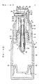
図1は、本発明の一実施例であるディスペンサー容器1を示す断面図である。本実施例に係るディスペンサー容器1は、例えば液状ファンデーションのように粉体を混入した液体或いは乳液のように粘性を有する液体を内容物15とするものである。
【0019】
ディスペンサー容器1は、大略すると容器本体2とディスペンサー3とにより構成されている。容器本体2は、例えば樹脂よりなる硬質の容器であり、その上部に内容物15を取り出す開口5を有している。また、容器本体2の開口5の外周所定位置には、スクリューキャップ6を装着するためのネジが形成されている。
【0020】
本実施例に係る容器本体2は、その内部に中皿4が設けられている。この中皿4は容器本体2の内壁と液密に摺接するシール部32を有しており、内容物15はこのシール部32の上部の領域に充填されている(以下、この領域を内容物充填部13という)。
【0021】
また、中皿4は、容器本体2の内壁に沿って図中矢印X2方向に移動可能な構成とされている。即ち、本実施例に係る容器本体2は、中皿4が移動することにより内容物充填部13内の空間、即ち内容物15が充填された空間(以下、内容物充填空間という)を収縮させる構成とされている。
【0022】
続いて、ディスペンサー3について説明する。ディスペンサー3は、大略するとスクリューキャップ6,シリンダー7,第1のプランジャー8,第2のプランジャー9,ノズル開閉機構10,及び液密遮蔽膜11等により構成されている。
【0023】
スクリューキャップ6はシリンダー7を一体的に形成した構成とされており、前記した容器本体2に螺着される。よって、スクリューキャップ6を容器本体2に螺着することにより、シリンダー7は容器本体2に挿入された状態で固定される。
【0024】
シリンダー7は筒状の部材であり、下端部には容器本体2の内容物充填部13と連通する下部開口12が形成されている。また、シリンダー7の下部開口12より若干上方位置には下部弁座部34が形成されており、この下部弁座部34上には下部逆止弁として機能するポペット40が設けられている。
【0025】
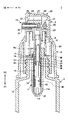
ポペット40は、シリンダー7の内部において図中矢印X1,X2方向に移動可能な構成とされている。このポペット40は、図2に拡大して示すように、上部に位置する小径部41と、下部に位置する大径部42とにより構成されている。そして、大径部42の下端部が下部弁座部34と当接することにより下部開口12を閉弁し、下部弁座部34から離間することにより下部開口12を開弁する構成とされている。
【0026】
更に、シリンダー7の内部には、液密遮蔽膜11が設けられている。この液密遮蔽膜11は、後述する操作ボタン21の押圧操作に伴いX1,X2方向に移動するプランジャー8の動作に従い変形し得る構成とされている。具体的には、本実施例では液密遮蔽膜11の形状を変形し易い蛇腹形状とし、かつ液密遮蔽膜11の材質として例えば低密度ポリエチレン,ゴム,エラストマー等の軟質で可撓性を有し、更に経時変形の少ない材質を選定している。
【0027】
この液密遮蔽膜11の下端部11aはシリンダー7に液密に接着されることにより接続されており、また上端部にはスライド弁14が配設されている。このスライド弁14はシリンダー7のシリンダー内壁7aに対して液密に摺接すると共に、後述する第2のプランジャー9の外周にも液密に摺接した構成とされている。内容物15は、この液密遮蔽膜11の内部の空間(以下、遮蔽膜内空間16という)に充填されることとなる。
【0028】
このように、液密遮蔽膜11の下端部11aをシリンダー7に液密に接続すると共に上端部にシリンダー内壁7a及び第2のプランジャー9と液密に摺接するスライド弁14を設けたことにより、内容物15がシリンダー7のシリンダー内壁7aに触れない構成とすることができる。即ち、内容物15は遮蔽膜内空間16内に位置するため、液密遮蔽膜11により内容物15とシリンダー内壁7aとを隔離することができる。よって、従来のように内容物15が直接シリンダー内壁7aと接触することがないため、シリンダー内壁7aに傷が付くことを防止できる。従って、スライド弁14がシリンダー内壁7aを摺接しても、このスライド弁14の動作に不良が発生するようなことはない。
【0029】
第1及び第2のプランジャー8,9はいずれもパイプ状の部材であり、一体的な構成とされている。具体的には、大径とされた第1のプランジャー8の内部に第2のプランジャー9を嵌入し接着することにより一体化した構成とされている。尚、本実施例では金型成形上の問題からプランジャーを第1及び第2のプランジャー8,9により構成しているが、この問題がないなら1本のパイプ状部材でプランジャーを形成してもよい。
【0030】
第1のプランジャー8の上端部には、後述するノズルヘッド20が取り付けられている。また、第1のプランジャー8の下部内部には、第2のプランジャー9の上部が固定される。更に、第1のプランジャー8の下端部36は、第1のプランジャー8の移動(X1方向への移動)により、前記したスライド弁14と係合しうるよう構成されている。
【0031】
また、第2のプランジャー9の下部には、連通孔37,突出部38,及び係合部39が形成されている。連通孔37は、第2のプランジャー9の壁を貫通するよう形成されている。
【0032】
この連通孔37は、操作ボタン21が押圧操作されていない状態(図1,図2に示す状態)にいおて、スライド弁14により閉弁されるよう構成されている。よってこの閉弁状態では、第2のプランジャー9の内部通路9aと遮蔽膜内空間16とは隔離された状態となる。尚、連通孔37の形成個数は、単数でも複数であってもよい。
【0033】
突出部38は、第2のプランジャー9の外周より外側に向けて(シリンダー内壁7aに向けて)、若干突出するよう形成されている。この突出部38は、スライド弁14と係合するよう、その突出量が設定されている。しかしながらこの突出部38は、シリンダー内壁7aからは離間するよう構成されている。
【0034】
また、係合部39は、前記したポペット40の小径部41と係合するよう構成されている。この係合部39とポペット40は液密に係合するよう構成されており、よって後述する内容物15の吐出操作時に、係合部39とポペット40との係合位置で内容物15が流れるようなことはない。更に、係合部39のポペット40を係合する係合力の強さは、少なくとも内容物15の吐出操作時に内容物15に印加される加圧或いは負圧力によっては、係合部39に対してポペット40が移動しない強さに設定されている。
【0035】
続いて、ノズル開閉機構10について説明する。ノズル開閉機構10は、第1のプランジャー8の上端部に取り付けらるものであり、大略するとノズルヘッド20,駆動カム部22,ノズルベース23,コイルスプリング24,ノズル25,弁部材28,コイルスプリング29,及び従動カム部材30等により構成されている。
【0036】
ノズルベース23は第1の第1のプランジャー8に固定されており、よって第1のプランジャー8はノズルベース23と一体的に移動する構成とされている。また、ノズルベース23とスクリューキャップ6との間にはコイルスプリング24が介装されており、よってノズルベース23はコイルスプリング24の弾性力により常に矢印X2方向に弾性付勢された構成とされている。更に、このノズルベース23の上部には、ノズルヘッド20が装着されている。
【0037】
ノズルヘッド20は、ノズルベース23に対して図中矢印X1,X2方向に微小量移動可能な構成とされている。このノズルヘッド20の上端部には、内容物15の吐出時に押圧される操作ボタン21が形成されている。また、ノズルヘッド20の矢印Y2方向端部には上下方向に長く形成された長孔27が形成されている。更に、ノズルヘッド20の内部の矢印Y1方向位置には、下方(X1方向)に向け延出する駆動カム部22が形成されている。
【0038】
ノズル25は、ノズルベース23の上部に固定されている。このノズル25は筒状形状を有しており、矢印Y2方向端部には内容物15を吐出するための吐出口26が形成されている。このノズル25の内部には、弁部材28が配設されている。
【0039】
弁部材28は、吐出口26内を矢印Y1,Y2方向に移動可能な構成とされている。また、ノズル25の内部には弁部材28と共にコイルスプリング29が設けられており、弁部材28はこのコイルスプリング29により矢印Y2方向に常時弾性付勢された構成とされている。コイルスプリング29に付勢されて弁部材28がY2方向に変位することにより、弁部材28の先端部は吐出口26と当接する。これにより、吐出口26は閉蓋された状態となる。
【0040】
一方、弁部材28のY1方向端部には従動カム部材30が取り付けられている。この従動カム部材30は、弁部材28と一体的に移動する構成とされている。また、従動カム部材30には、前記したノズルヘッド20に形成された駆動カム部22と係合する傾斜カム面31が形成されている。傾斜カム面31は、図示されるような傾斜面を有しており、駆動カム部22もこれに対応した傾斜面を有している。
【0041】
よって、ノズルヘッド20がX1方向に移動すると、駆動カム部22は傾斜カム面31を押圧し、これにより従動カム部材30をY1方向に移動付勢する。前記ように、従動カム部材30は弁部材28と一体的に移動する構成とされているため、従動カム部材30の移動に伴い弁部材28はコイルスプリング29の弾性力に抗してY1方向に移動する。これにより、ノズル25の吐出口26は開かれた状態、即ち内容物15を吐出しうる状態となる。
【0042】
続いて、上記構成とされたディスペンサー容器1の動作に対説明する。
【0043】
図1及び図2は、操作ボタン21が押圧操作されていない状態(操作前状態という)を示している。この操作前状態では、コイルスプリング24は伸長している。このため、液密遮蔽膜11は伸長し、また第1及び第2のプランジャー8,9はX2方向限に移動した状態となっている。
【0044】
また、コイルスプリング29も伸長した状態となっているため、弁部材28はY2方向に移動して吐出口26を閉弁している。更に、弁部材28がY2方向に移動することにより、従動カム部材30もY2方向に移動しており、よって傾斜カム面31と係合した駆動カム部22(即ち、ノズルヘッド20)はX2方向に移動されている。尚、操作前状態では、容器本体2内の内容物充填部13、シリンダー7内の遮蔽膜内空間16、第1及び第2のプランジャー8,9、及び吐出口26内に内容物15が充填されているものとして以下の説明を行なう。
【0045】
ディスペンサー容器1で内容物15を吐出させるには、操作ボタン21を押圧操作する。これにより、先ずノズルベース23に対してノズルヘッド20がX1方向に移動し、駆動カム部22が従動カム部材30をY1方向に移動させる。これにより、弁部材28はコイルスプリング29の弾性力に抗してY1方向に移動し、ノズル25の吐出口26は開かれる。
【0046】
更に操作ボタン21を押圧し、弁部材28がY1方向限まで移動すると、ノズルベース23はコイルスプリング24の弾性力に抗してノズルヘッド20と共にX1方向に移動を開始し、これにより第1及び第2のプランジャー8,9、及び第2のプランジャー9に係合されているポペット40もX1方向に移動(下動)を開始する。前記したコイルスプリング24とコイルスプリング29の弾性力の強さは、先ずノズルヘッド20のみが移動し、続いてノズルヘッド20と共にノズルベース23が移動するよう設定されている。
【0047】
ここで、先ず図2に矢印Hで示す長さだけ、第1及び第2のプランジャー8,9が下動する時の動作に注目する。図2に矢印Hで示す距離は、操作前状態における第1のプランジャー8の下端部36とスライド弁14との離間距離である。従って、第1及び第2のプランジャー8,9が寸法Hだけ下動することにより、下端部36はスライド弁14と当接する。この第1及び第2のプランジャー8,9が寸法Hだけ下動する間は、スライド弁14はシリンダー内壁7aとの摩擦力により移動することはなく、操作前状態を維持している。
【0048】
また、第1及び第2のプランジャー8,9が寸法Hだけ下動することにより、第2のプランジャー9に形成されている連通孔37も寸法Hだけ下動する。よって、連通孔37はスライド弁14から離間し(即ち、開弁され)、第2のプランジャー9内の内部通路9aと遮蔽膜内空間16は、連通孔37により連通された状態となる。
【0049】
更に、操作ボタン21を押圧して第1及び第2のプランジャー8,9を寸法H以上に下動させると、第2のプランジャー9の係合部39に係合されていたポペット40の下端が下部弁座部34に当接する。これにより、下部開口12は閉弁され、遮蔽膜内空間16と容器本体2内の内容物充填部13は隔離された状態となる。
【0050】
また、上記の更なる第1及び第2のプランジャー8,9の下動により、第1のプランジャー8の下端部36はスライド弁14を下方に向け押圧する。これにより、液密遮蔽膜11はスライド弁14のX1方向の移動に伴い圧縮され、遮蔽膜内空間16内の内容物15は加圧される。
【0051】
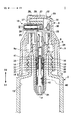
この際、上記のように下部開口12はポペット40により閉弁されており、また連通孔37は遮蔽膜内空間16と内部通路9aを連通している。よって、第1及び第2のプランジャー8,9の下動により加圧された内容物15は、第1及び第2のプランジャー8,9内をX2方向に移動(上動)し、ノズル25内に進入して吐出口26から吐出される。図3は、吐出口26から内容物15が吐出されている状態を示している。
【0052】
この吐出動作の際、前記のように液密遮蔽膜11を設けることにより内容物15はシリンダー内壁7aと隔離されているため、スライド弁14の適正動作を確保でき、よってディスペンサー容器1の作動不良を防止することができる。
【0053】
一方、上記の吐出動作が終了すると、操作ボタン21に対する押圧操作が解除される。これにより、ノズルベース23はコイルスプリング24の弾性復元力によりX2方向に移動を開始する。また、ノズルヘッド20もノズルベース23に対してX2方向に移動し、更にノズルベース23に一体的に設けられている第1及び第2のプランジャー8,9もX2方向に移動を開始する。
【0054】
ノズルヘッド20がノズルベース23に対してX2方向に移動すると、これに伴い駆動カム部22もX2方向に移動し、コイルスプリング29の弾性復元力により従動カム部材30及び弁部材28はY2方向に移動する。よって、ノズル25の吐出口26は再び弁部材28により閉塞されるため、吐出口26内に有る内容物15が外気に触れることはなくなる。
【0055】
このように、操作ボタン21の操作解除が行なわれた直後において吐出口26は弁部材28により塞がれるため、内容物15が大気と触れることを確実に防止でき、ノズル25に内容物15が付着固化することを防止できる。よって、粉体を混入した液体及び高粘度の液体を内容物としても、適正吐出処理を行なうことが可能となる。
【0056】
一方、第1及び第2のプランジャー8,9がX2方向に移動(上動)を開始すると、先ず第2のプランジャー9の係合部39と係合しているポペット40がX2方向に移動して下部弁座部34から離間し、よって下部開口12が開弁される。これにより、再び内容物充填部13と遮蔽膜内空間16は連通した状態となる。
【0057】
また、第1及び第2のプランジャー8,9が上動を開始した直後は、スライド弁14はシリンダー内壁7aとの摩擦力により直ちに移動することはない。このため、第1及び第2のプランジャー8,9が上動することにより、具体的には前記した寸法Hだけ上動することにより、第2のプランジャー9に形成されている連通孔37は再びスライド弁14と係合して閉弁される。これにより、内部通路9aと遮蔽膜内空間16は再び遮断された構成となる。
【0058】
更に、第1及び第2のプランジャー8,9が上動することにより、第1のプランジャー8に形成されている突出部38がスライド弁14と係合する。よって、突出部38がスライド弁14と係合した後は、第1及び第2のプランジャー8,9の上動に伴い、スライド弁14に接続された液密遮蔽膜11は伸長する。
【0059】
このように、収縮されていた液密遮蔽膜11が伸長付勢されることにより、遮蔽膜内空間16の内部は負圧となる。この時、上記のように連通孔37は閉弁されており、下部開口12は開弁された状態となっている。従って、第1及び第2のプランジャー8,9が上動により、遮蔽膜内空間16内に発生する負圧により、内容物充填部13内の内容物15は遮蔽膜内空間16内に吸引される。
【0060】
この際、内容物充填部13内は負圧となるが、従来では内容物充填空間が外部に対して気密になっており、また収縮できない構成とされていため、上記吸引時に外部から容器本体の内容物充填空間内に空気を送り込むためのエア取り込み機構が設けられていた。しかしながら、このエア取り込み機構は構成が複雑で、ディスペンサーの作成を困難にするものであったことは前述した通りである。
【0061】
これに対して本実施例に係るディスペンサー容器1は、容器本体2の内壁に沿って液密に摺動する中皿4を設けることにより、内容物充填部13を収縮しうる構成となっている。よって、内容物15を内容物充填部13からシリンダー7(遮蔽膜内空間16)内に吸引しても、内容物充填空間13はこれに伴い収縮するため、外部の空気を内容物充填空間13内に供給する必要はなくなる。
【0062】
従って、従来必要とされたエア取り込み機構を不要とすることができ、ディスペンサー容器1の構成を簡単化することができる。また、内容物15が大気に触れることがなくなるため、内容物15に酸化等の変質が発生することも防止できる。
【0063】
また、本実施例に係るディスペンサー容器1は、上記したようにスライド弁14により連通孔37を開閉弁する機構、及びポペット40により下部開口12を開閉弁する機構は、いずれも第1及び第2のプランジャー8,9の上下動を駆動源として開閉動作を行なっている。従って、内容物15の比重が大きく或いは粘度が高い場合であっても、従来のボールの自重で弁を開閉構成する構成の弁機構に比べてシール力を高めることができ、内容物15の突出動作を適正に行なうことができる。
【0064】
尚、上記実施例では、内容物15の吐出に伴い内容物充填部13内の内容物充填空間を収縮させるために、容器本体2内に中皿4を設けた構成とした。しかしながら、内容物15の吐出に伴い内容物充填部13内の内容物充填空間を収縮させる構成はこれに限定されるものではなく、例えば容器本体2を収縮可能な包装体(例えば、ビニール袋やアルミパウチ)で構成してもよく、また容器本体2内に別個に収縮可能な内袋を設ける構成としてもよい。
【0065】
【発明の効果】
上述の如く本発明によれば、粉末を混入した液体及び高粘度の液体を内容物としても、適正に吐出処理を行なうことができる。
【図面の簡単な説明】
【図1】本発明の一実施例であるディスペンサー容器の断面図である。
【図2】ノズルヘッドを押し下げ操作していない状態のディスペンサー容器の拡大図である。
【図3】ノズルヘッドを押し下げ操作している状態のディスペンサー容器の拡大図である。
【符号の説明】
1 ディスペンサー容器
2 容器本体
3 ディスペンサー
7 シリンダー
8 第1のプランジャー
9 第2のプランジャー
10 ノズル開閉機構
11 液密遮蔽膜
12 下部開口
13 内容物充填部
14 スライド弁
15 内容物
16 遮蔽膜内空間
20 ノズルヘッド
21 操作ボタン
22 駆動カム部
24,29 コイルスプリング
25 ノズル
26 吐出口
28 弁部材
30 従動カム部材
31 傾斜カム面
36 下端部
37 連通孔
38 突出部
39 係合部
40 ポペット[0001]
TECHNICAL FIELD OF THE INVENTION
The present invention relates to a dispenser container, and more particularly to a dispenser container containing a liquid mixed with a powder and a high-viscosity liquid.
[0002]
[Prior art]
Generally, in a dispenser for filling a shampoo, a rinse, or the like, a piston is provided that can slide up and down along the inner wall of the cylinder. A pressure plunger is attached to the upper part of the piston, and a check valve consisting of a ball valve is attached to the lower end of the cylinder and the upper end of the pressure plunger.
[0003]
A nozzle head is provided integrally with the upper part of the pressurizing plunger. By operating the nozzle head, the piston connected to the pressurizing plunger becomes liquid-tight downward with respect to the cylinder. Slide. By this pressing operation, the contents in the cylinder are pressurized to increase the discharge pressure, and the upper check valve is pushed up by the pressure to discharge the contents from the nozzle tip.
[0004]
In this type of conventional dispenser, the inner wall of the cylinder is in direct contact with the contents, and the piston slides on the inner wall with which the contents are in direct contact. For this reason, when the liquid containing the powder is used as the content, the powder adheres to the inner wall of the cylinder or a portion of the piston that slides with the inner wall of the cylinder, and damages the sliding surfaces of the piston and the cylinder, resulting in malfunction. There was a problem that caused.
Also, depending on the components of the contents, there is a problem that the piston swells and deforms, and the lubricant applied to the piston part elutes in the contents, which also causes a malfunction near the piston part. Was.
[0005]
Therefore, as disclosed in
[0006]
[Patent Document 1]
JP 08-119310 A
[Problems to be solved by the invention]
However, in the dispenser container provided with the watertight shielding film in the cylinder described above, although the malfunction due to the scratches on the sliding surfaces of the piston and the cylinder can be prevented, if the contents remain in the nozzle, it is exposed to the atmosphere. As a result, the powder solidifies and adheres to the nozzle, so that proper discharge of the contents cannot be performed. The same applies to the case where a liquid having a high viscosity is used as the content.If the content adheres to the discharge port and solidifies upon contact with the atmosphere, there is still a problem that the proper discharge of the content cannot be performed. Was.
[0008]
After discharging the contents by pressing the nozzle head, the pressurizing plunger is moved upward by the spring to the position before the pressing operation. At this time, the contents are sucked into the cylinder from the space filled with the contents of the container body (content filling space) with the upward movement of the pressurized plunger. At this time, since the content filling space is conventionally made airtight to the outside and cannot be shrunk, the content can not be smoothly suctioned simply by performing the suction (in the container body). Is negative pressure).
[0009]
Therefore, conventionally, the dispenser container has been provided with an air intake mechanism having an intake hole for sending air from the outside into the content filling space of the container body during the suction. However, this air intake mechanism needs to open the intake hole when the above-mentioned contents are sucked and communicate the outside with the contents filling space, and close the intake hole at other times. There is a problem that it is difficult to configure.
[0010]
Furthermore, since the ball valve used as the check valve is configured to control the backflow of the contents by using the weight of the ball, the contents having a large specific gravity or the contents having a high viscosity are mixed by mixing the powder. In such a case, there is a problem that the sealing force of the ball is insufficient, so that a proper ejection operation cannot be performed.
[0011]
The present invention has been made in view of the above points, and an object of the present invention is to provide a dispenser container capable of performing a proper discharge process even when a liquid containing a powder and a high-viscosity liquid are used as contents.
[0012]
[Means for Solving the Problems]
In order to solve the above problems, the present invention provides:
By pushing down the nozzle head, the plunger is moved down in the cylinder to pressurize the contents in the cylinder to discharge the contents, and the plunger is moved up in the cylinder by releasing the pushing down operation, In a dispenser container configured to suction the content from a container body filled with the content into a cylinder,
A valve member that opens and closes a discharge port from which the contents are discharged, a biasing unit that biases the valve member in a closing direction, and a valve member that pushes the valve member against the biasing unit by pressing down the nozzle head. A nozzle opening and closing mechanism that opens to open the discharge port,
One end is connected to the lower end of the cylinder in a liquid-tight manner, and the other end is provided with a slide valve that comes into sliding contact with the inner wall of the cylinder in a liquid-tight manner. A liquid-tight shielding film that isolates
The content is filled, the content is filled with a volume shrinking with a decrease in the content accompanying the discharge from the nozzle,
The upper communication hole, which is disposed above the liquid-tight shielding film and communicates the plunger and the inner space of the shielding film by the downward movement of the plunger, is opened. An upper valve mechanism for closing the upper communication hole,
A lower valve mechanism that closes a lower communication hole that communicates the space in the shielding film with the inside of the container body by lowering the plunger, and opens the lower communication hole by moving the plunger upward. And characterized in that:
[0013]
According to the above invention, one end is liquid-tightly connected to the plunger, and the other end is provided with the liquid-tight shielding film connected in a liquid-tight manner to the inner wall of the cylinder, and the content in the space in the shielding film is provided. Can be prevented from touching the cylinder to prevent malfunction due to scratches on the sliding surface of the cylinder.
[0014]
In addition, by providing a nozzle opening and closing mechanism, the valve member opens the discharge port only when the nozzle head is pressed down, and closes the discharge port at other times, so that the contents can be prevented from contacting the atmosphere, and An object can be prevented from sticking and solidifying. Therefore, it is possible to perform a proper ejection process even if the liquid containing the powder and the high-viscosity liquid are used as contents.
[0015]
In addition, as the contents are reduced due to the discharge from the nozzle, the contents filling section is provided to shrink the contents filling space filled with the contents. Since the material filling space shrinks accordingly, there is no need to supply external air into the content filling space. Therefore, the conventionally required air intake mechanism can be eliminated, and the configuration of the dispenser container can be simplified.
[0016]
Further, since the upper valve mechanism and the lower valve mechanism open and close the upper communication hole or the lower communication hole by the vertical movement of the plunger, even if the specific gravity of the contents is large or the viscosity is high, the conventional weight of the ball can be reduced. Thus, the sealing force can be increased as compared with a valve mechanism having a configuration in which the valve is opened and closed, and the discharge operation can be appropriately performed.
[0017]
BEST MODE FOR CARRYING OUT THE INVENTION
Next, embodiments of the present invention will be described with reference to the drawings.
[0018]
FIG. 1 is a sectional view showing a
[0019]
The
[0020]
The container
[0021]
The inner plate 4 is configured to be movable in the direction of arrow X2 in the figure along the inner wall of the
[0022]
Next, the
[0023]
The screw cap 6 has a structure in which a cylinder 7 is integrally formed, and is screwed to the container
[0024]
The cylinder 7 is a cylindrical member, and has a
[0025]
The
[0026]
Further, a liquid-
[0027]
The
[0028]
As described above, the
[0029]
Each of the first and
[0030]
At the upper end of the first plunger 8, a
[0031]
In addition, a
[0032]
The
[0033]
The protruding
[0034]
The engaging
[0035]
Next, the nozzle opening /
[0036]
The
[0037]
The
[0038]
The
[0039]
The
[0040]
On the other hand, a driven
[0041]
Therefore, when the
[0042]
Next, the operation of the
[0043]
1 and 2 show a state where the operation button 21 is not pressed (hereinafter referred to as a pre-operation state). In this pre-operation state, the
[0044]
Further, since the coil spring 29 is also in the extended state, the
[0045]
In order to discharge the
[0046]
When the operation button 21 is further pressed and the
[0047]
Here, first, attention is paid to the operation when the first and
[0048]
When the first and
[0049]
Further, when the operation button 21 is pressed to lower the first and
[0050]
Further, due to the further downward movement of the first and
[0051]
At this time, the
[0052]
At the time of this discharge operation, the
[0053]
On the other hand, when the above-described ejection operation ends, the pressing operation on the operation button 21 is released. Thus, the
[0054]
When the
[0055]
Thus, immediately after the operation of the operation button 21 is released, the
[0056]
On the other hand, when the first and
[0057]
Immediately after the first and
[0058]
Further, as the first and
[0059]
As described above, the contracted liquid-
[0060]
At this time, the inside of the
[0061]
On the other hand, the
[0062]
Therefore, the conventionally required air intake mechanism can be eliminated, and the configuration of the
[0063]
In the
[0064]
In the above embodiment, the inner plate 4 is provided in the container
[0065]
【The invention's effect】
As described above, according to the present invention, it is possible to properly perform a discharge process even when a liquid containing a powder and a high-viscosity liquid are used as contents.
[Brief description of the drawings]
FIG. 1 is a sectional view of a dispenser container according to an embodiment of the present invention.
FIG. 2 is an enlarged view of the dispenser container in a state where the nozzle head is not pressed down.
FIG. 3 is an enlarged view of the dispenser container in a state where a nozzle head is being pressed down.
[Explanation of symbols]
DESCRIPTION OF
Claims (1)
前記内容物が吐出される吐出口を開閉する弁部材と、該弁部材を閉方向に付勢する付勢手段と、前記ノズルヘッドの押し下げ操作により前記付勢手段に抗して前記弁部材を開動作させ前記吐出口を開放するノズル開閉機構と、
一端がシリンダー下端と液密に接続されると共に他端にシリンダー内壁と液密に摺接するスライド弁が設けられており、内部に形成される遮蔽膜内空間内の前記内容物が前記シリンダーと触れないよう隔離する液密遮蔽膜と、
前記内容物が充填されており、前記ノズルからの吐出に伴う前記内容物の減少に伴い容積が収縮する内容物充填部と、
前記液密遮蔽膜の上部に配設されており、前記プランジャーの下動により前記プランジャーと前記遮蔽膜内空間を連通する上部連通孔を開状態とすると共に、前記ブランジャーの上動により前記上部連通孔を閉状態とする上弁機構と、
前記プランジャーの下動により前記遮蔽膜内空間と前記容器本体内とを連通する下部連通孔を閉状態とし、かつ、前記ブランジャーの上動により前記下部連通孔を開状態とする下弁機構と
を有することを特徴とするディスペンサー容器。By pushing down the nozzle head, the plunger is moved down in the cylinder to pressurize the contents in the cylinder to discharge the contents, and the plunger is moved up in the cylinder by releasing the pushing down operation, In a dispenser container configured to suction the content from a container body filled with the content into a cylinder,
A valve member that opens and closes a discharge port from which the contents are discharged, a biasing unit that biases the valve member in a closing direction, and a valve member that pushes the valve member against the biasing unit by pressing down the nozzle head. A nozzle opening and closing mechanism that opens to open the discharge port,
One end is connected to the lower end of the cylinder in a liquid-tight manner, and the other end is provided with a slide valve that comes into sliding contact with the inner wall of the cylinder in a liquid-tight manner. A liquid-tight shielding film that isolates
The content is filled, the content is filled with a volume shrinking with a decrease in the content accompanying the discharge from the nozzle,
The upper communication hole, which is disposed above the liquid-tight shielding film and communicates the plunger and the inner space of the shielding film by the downward movement of the plunger, is opened. An upper valve mechanism for closing the upper communication hole,
A lower valve mechanism that closes a lower communication hole that communicates the space in the shielding film with the inside of the container body by lowering the plunger, and opens the lower communication hole by moving the plunger upward. A dispenser container comprising:
Priority Applications (1)
| Application Number | Priority Date | Filing Date | Title |
|---|---|---|---|
| JP2003094032A JP2004299727A (en) | 2003-03-31 | 2003-03-31 | Dispenser container |
Applications Claiming Priority (1)
| Application Number | Priority Date | Filing Date | Title |
|---|---|---|---|
| JP2003094032A JP2004299727A (en) | 2003-03-31 | 2003-03-31 | Dispenser container |
Publications (1)
| Publication Number | Publication Date |
|---|---|
| JP2004299727A true JP2004299727A (en) | 2004-10-28 |
Family
ID=33406688
Family Applications (1)
| Application Number | Title | Priority Date | Filing Date |
|---|---|---|---|
| JP2003094032A Withdrawn JP2004299727A (en) | 2003-03-31 | 2003-03-31 | Dispenser container |
Country Status (1)
| Country | Link |
|---|---|
| JP (1) | JP2004299727A (en) |
Cited By (8)
| Publication number | Priority date | Publication date | Assignee | Title |
|---|---|---|---|---|
| KR100935909B1 (en) | 2009-03-23 | 2010-01-06 | 변재삼 | Airless Type Cosmetic Container |
| KR100935907B1 (en) | 2008-10-20 | 2010-01-06 | 변재삼 | Airless type cosmetics vessel |
| KR101036269B1 (en) | 2009-04-22 | 2011-05-23 | 변재삼 | Airless type cosmetic container with side discharge passage |
| KR101193000B1 (en) | 2010-05-07 | 2012-10-19 | 우연춘 | Dispenser |
| KR101339855B1 (en) | 2011-04-11 | 2013-12-10 | 주식회사 우경아이앤아이 | Content discharge courage |
| JP2015143120A (en) * | 2014-01-31 | 2015-08-06 | 株式会社吉野工業所 | discharge container |
| JP2015143114A (en) * | 2014-01-31 | 2015-08-06 | 株式会社吉野工業所 | discharge container |
| CN105532624A (en) * | 2016-03-01 | 2016-05-04 | 湖州织里华宁园艺工程有限公司 | Solid-liquid mixing box for horticulture |
-
2003
- 2003-03-31 JP JP2003094032A patent/JP2004299727A/en not_active Withdrawn
Cited By (8)
| Publication number | Priority date | Publication date | Assignee | Title |
|---|---|---|---|---|
| KR100935907B1 (en) | 2008-10-20 | 2010-01-06 | 변재삼 | Airless type cosmetics vessel |
| KR100935909B1 (en) | 2009-03-23 | 2010-01-06 | 변재삼 | Airless Type Cosmetic Container |
| KR101036269B1 (en) | 2009-04-22 | 2011-05-23 | 변재삼 | Airless type cosmetic container with side discharge passage |
| KR101193000B1 (en) | 2010-05-07 | 2012-10-19 | 우연춘 | Dispenser |
| KR101339855B1 (en) | 2011-04-11 | 2013-12-10 | 주식회사 우경아이앤아이 | Content discharge courage |
| JP2015143120A (en) * | 2014-01-31 | 2015-08-06 | 株式会社吉野工業所 | discharge container |
| JP2015143114A (en) * | 2014-01-31 | 2015-08-06 | 株式会社吉野工業所 | discharge container |
| CN105532624A (en) * | 2016-03-01 | 2016-05-04 | 湖州织里华宁园艺工程有限公司 | Solid-liquid mixing box for horticulture |
Similar Documents
| Publication | Publication Date | Title |
|---|---|---|
| US8006870B2 (en) | Discharger for a flowable medium | |
| EP3078313A1 (en) | Pump device and methods for making the same | |
| US8444017B2 (en) | Pump-equipped container and duplex discharge container | |
| JPH1176883A (en) | Dispenser for liquid or pasty products with improved pumping means | |
| WO2003099453A1 (en) | Pressure accumulator-type liquid spraying device | |
| JP2004299727A (en) | Dispenser container | |
| US20060255072A1 (en) | Metering pump arrangement and method for the production of a filled metering pump arrangement | |
| JP2010504852A (en) | Liquid dispenser device | |
| KR200311503Y1 (en) | a dispenser vessel | |
| KR102064062B1 (en) | Pump type liquid sealed container | |
| JPH09267855A (en) | Dispenser | |
| JP5384127B2 (en) | Liquid ejector | |
| JP4038344B2 (en) | Accumulated liquid ejector | |
| JP2004299726A (en) | Dispenser container | |
| JP7245081B2 (en) | liquid discharge pump | |
| JP2000079959A (en) | Piston structure for dispenser container | |
| JP4483260B2 (en) | Liquid application container | |
| CN114599456A (en) | pump container | |
| JP4679014B2 (en) | Viscous liquid dispensing container | |
| CN116873392A (en) | Product dispenser and container with the product dispenser | |
| JP2005066187A (en) | Dropping device | |
| JP2556686Y2 (en) | dispenser | |
| JPH0513564U (en) | Day Spencer | |
| KR102590170B1 (en) | Cartridge replaceable cosmetic container with automatic nozzle opening and closing | |
| JP4588851B2 (en) | Pump dispenser |
Legal Events
| Date | Code | Title | Description |
|---|---|---|---|
| A300 | Application deemed to be withdrawn because no request for examination was validly filed |
Free format text: JAPANESE INTERMEDIATE CODE: A300 Effective date: 20060606 |