JP2004306754A - Hydraulic excavator air conditioner - Google Patents
Hydraulic excavator air conditioner Download PDFInfo
- Publication number
- JP2004306754A JP2004306754A JP2003102159A JP2003102159A JP2004306754A JP 2004306754 A JP2004306754 A JP 2004306754A JP 2003102159 A JP2003102159 A JP 2003102159A JP 2003102159 A JP2003102159 A JP 2003102159A JP 2004306754 A JP2004306754 A JP 2004306754A
- Authority
- JP
- Japan
- Prior art keywords
- air
- cab
- conditioning unit
- air conditioning
- air conditioner
- Prior art date
- Legal status (The legal status is an assumption and is not a legal conclusion. Google has not performed a legal analysis and makes no representation as to the accuracy of the status listed.)
- Granted
Links
Images

Classifications
-
- B—PERFORMING OPERATIONS; TRANSPORTING
- B60—VEHICLES IN GENERAL
- B60H—ARRANGEMENTS OF HEATING, COOLING, VENTILATING OR OTHER AIR-TREATING DEVICES SPECIALLY ADAPTED FOR PASSENGER OR GOODS SPACES OF VEHICLES
- B60H1/00—Heating, cooling or ventilating devices
- B60H1/00357—Air-conditioning arrangements specially adapted for particular vehicles
- B60H1/00378—Air-conditioning arrangements specially adapted for particular vehicles for tractor or load vehicle cabins
Landscapes
- Physics & Mathematics (AREA)
- Thermal Sciences (AREA)
- Engineering & Computer Science (AREA)
- Mechanical Engineering (AREA)
- Component Parts Of Construction Machinery (AREA)
- Air-Conditioning For Vehicles (AREA)
Abstract
Description
【0001】
【発明の属する技術分野】
本発明は、油圧ショベルのキャブに設置される空調装置に関する。
【0002】
【従来の技術】
油圧ショベル等の建設機械には、乗降用ドアと窓を有する壁面とで運転席周囲を囲った室内に、作業機操作装置および走行操縦装置を設けたキャブを備えたものがあり、このキャブ内に操作性向上(窓ガラスのデフロスタ等)および居住性向上(冷暖房、エアコンディション)のため空気調和装置(以下、空調装置と言う。)を設置したものが近年多く使用されている。従来、この空調装置は、キャブ内スペースを広く確保すること、そしてオペレータの視界性を確保することを目的として、例えばオペレータシートとキャブ後壁面との間(例えば、特許文献1参照。)、キャブ後壁部やオペレータシート下方の床面(例えば、特許文献2参照。)、またはキャブ天井面(例えば、特許文献3参照。)などに設置されている。
【0003】
【特許文献1】
特開平8−183323号公報(第3頁、第1図)
【特許文献2】
特開2001−55760号公報(第4頁、第2,4図)
【特許文献3】
実開昭53−52549号公報(第3−5頁、第1−4図)
【0004】
【発明が解決しようとする課題】
しかしながら、上記従来の空調装置には、次の問題がある。
空調装置から吹き出されるエアを、オペレータの足元部および顔面部の近傍の吹き出し口と、前面および/または側面の窓ガラス近傍のデフロスタ用吹き出し口とに導くために、空調装置と各個所の吹き出し口とを接続する配風ダクトを布設する必要がある。ところが、これをキャブ内に布設すると、ダクトスペースの分だけキャブ内スペースが狭くなるという問題がある。また、空調装置と特定の吹き出し口とを接続するダクトが長くなり、特許文献1に記載されている例では、キャブ内後部の空調装置からオペレータ顔面部の近傍、前面と側面の窓ガラス近傍までそれぞれ布設するダクトが長くなり、特許文献2に記載されている例では、オペレータシート下方の空調装置からオペレータ顔面部の近傍、前面と側面の窓ガラス近傍までそれぞれ布設するダクト長が長くなり、特許文献3に記載されている例では、キャブ天井面の空調装置から足元部までのダクトが長くなるので、これらダクトの布設作業に時間がかかり、製造コストを高める要因となっている。
【0005】
本発明は、上記の問題点に着目してなされたもので、キャブ内スペースを広く確保でき、またキャブ内各要所に配風するダクトの布設作業が容易にできる油圧ショベルの空調装置を提供することを目的としている。
【0006】
【課題を解決するための手段、作用及び効果】
上記目的を達成するため、第1発明は、油圧ショベルのキャブに設置される空調装置において、キャブ内の右側前部に、空調ユニットを設置した構成としている。
【0007】
第1発明によれば、オペレータの顔面部および足元部と、前面および側面の窓ガラスとに共に近い位置である、キャブ内の右側前部に、空調ユニットを設置したため、長いダクト等の布設をすることなく、オペレータの顔面部および足元部、前面および/または側面の窓ガラスへの配風が非常に容易にできる。従って、ダクト布設作業時間が短くなり、製作コストを低減できると共に、ダクトスペースが少なくなるためキャブ内スペースを広く確保できる。
【0008】
第2発明は、油圧ショベルのキャブに設置される空調装置において、キャブの右側壁面の前部に、空調ユニットを取り付けた構成としている。
【0009】
第2発明によれば、オペレータの顔面部および足元部と、前面および側面の窓ガラスとに共に近い位置である、キャブの右側壁面の前部に、空調ユニットを取り付けたため、長いダクト等の布設をすることなく、オペレータの顔面部および足元部、前面および/または側面の窓ガラスへの配風が非常に容易にできる。従って、ダクト布設作業時間が短くなり、製作コストを低減できる。また、これによってダクトスペースが少なくなると共に、空調ユニットを壁面に取り付けたため、キャブ内スペースを広く確保できる。
【0010】
第3発明は、第1または第2発明において、前記空調ユニットは、キャブの内側および外側から出し入れ可能に、右側壁面に取り付けられた構成としている。
【0011】
第3発明によれば、空調ユニットをキャブの内側および外側から出し入れ可能に取り付けたため、キャブ単体での車両組立時には外側から右側壁面に取り付けでき、車両搭載後のメンテナンス等の時にはキャブ内側から取り出し、据付けができる。これにより、組立時およびメンテナンス時の作業性を向上できる。
【0012】
第4発明は、第3発明において、前記空調ユニットは、右側壁面の一部を兼ねて取り付けられた構成としている。
【0013】
第4発明によれば、空調ユニットを、右側壁面の一部を兼ねて取り付けているため、空調ユニットのキャブ内への出っ張り量が小さくなり、キャブ内スペースを広く確保できる。また、これにより、第3発明に係る、空調ユニットをキャブの内側および外側から出し入れ可能に取り付けるための構造を簡素化できる。
【0014】
第5発明は、第1、第2または第3発明において、前記空調ユニットの配管接続部は、キャブ外側に露出した部位に設けた構成としている。
【0015】
第5発明によれば、空調ユニットへの温水、冷媒ガスの配管を、キャブ外側に露出した部位に設けた配管接続部に接続できるため、キャブの側壁面や床面に配管を通すための孔や接続部が不要となり、これによって配管シール箇所が減ってシールが容易となると共に、ガス漏れや水漏れ箇所が少なくなり信頼性を向上できる。また、空調ユニットとラジエータ、ガスコンプレッサ等との間を略直線的にダイレクトに配管できるので、配管経路を短縮でき、配管作業が容易となる。
【0016】
第6発明は、第1または第2発明において、車両前側上部が前下がりの傾斜でカットされた形状を有する空調装置としている。
【0017】
第6発明によれば、空調装置(空調ユニットと、該空調ユニットに被せる内装カバーとを含む)は、車両前側上部が前下がりの傾斜でカットされた形状を有しているため、オペレータからの車両の前部右側方向の視野が空調装置で妨げられることがなく、オペレータの右前方視界を十分に確保できる。また、従来は、右前方視界性の低下を恐れて空調装置を設置することが無かったキャブ右側前部の位置に、空調装置を設置できるようになり、前述までの優れた効果が得られる。
【0018】
第7発明は、第1または第2発明において、前記空調ユニットに被せる内装カバーに、該空調ユニットから送風されたエアを所定方向に配風するダクトを設けた構成としている。
【0019】
第7発明によれば、空調ユニットに被せる内装カバーが、該空調ユニットから送風されたエアを配風するダクトを有しているため、新たにダクトを取り付ける必要が無く、ダクト布設スペースを節約してキャブ内スペースを広く確保できる。しかも、空調ユニットとダクトがこのカバーで隠れるので、見栄えを向上できる。
【0020】
第8発明は、油圧ショベルのキャブに設置される空調装置において、空調ユニットへ外気を導入する導入口は、キャブの右側壁面の、外装カバーよりも上方部位に設けた構成としている。
【0021】
第8発明によれば、キャブの右側壁面の、外装カバーよりも上方部位に設けた導入口の近傍は車両略中央に位置するため、この導入口から導入するエアは塵埃の混入や、エンジン冷却後の暖まったエアによる温度上昇の影響等が少ないので、空調用として好適なエアを導入できる。これにより、外気用フィルタの寿命の向上、空調効率の向上等が図れる。
【0022】
【発明の実施の形態】
以下に、本発明の実施形態を図面を参照して詳細に説明する。
【0023】
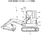
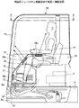
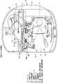
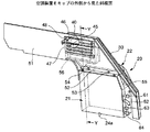
先ず図1〜3により、本発明の適用機例である後方超小旋回型の油圧ショベルの概要構成を説明する。図1は、本発明の適用機例である油圧ショベルの側面図であり、図2は同油圧ショベルの上部旋回体の側面一部断面図で、図3は図2のX−X矢視図である。
【0024】
これらの図において、油圧ショベル1は、下部走行体2上に上部旋回体3を旋回自在に搭載しており、上部旋回体3の下部に備えた旋回フレーム3aの前部中央部から左端部に亘ってキャブ10が設けられ、旋回フレーム3aの後端部にはカウントウエイト4が取り付けられている。このキャブ10は、旋回フレーム3aの前端部に設けたブラケット15に水平ピン16を介して前後方向揺動自在に連結されており、水平ピン16の回りに所定角度チルト可能となっている。キャブ10の中央部よりもやや後寄りに設けたオペレータシート11の下方で、カウンタウエイト4の前方には、エンジン7が設けられている。キャブ10の右側方の、旋回フレーム3aの右部には作動油タンク、燃料タンクが設置され、これらは外装カバー8で覆われている。また、旋回フレーム3aの前端部には、ブーム、アーム、バケット等を有する作業機5が垂直面内で揺動自在に取着されたスイングブラケット6が、左右揺動(以下、スイングという)自在に取り付けられている。なお、上記油圧ショベル1は、上部旋回体3の後端部の旋回軌跡が下部走行体2の左右履帯幅以内に収まる後方超小旋回型となっている。
【0025】
キャブ10の右側壁面の前部に、空調装置20が設けられている。この空調装置20は、冷房、暖房等の機能を有する空調ユニット21と、該空調ユニット21をキャブ10の内側から覆う内装カバー、および空調ユニット21が送風したエアを所定方向に配風するための空調用ダクトを兼ねた空調カバー22とを備えている。空調ユニット21は右側壁面の一部をなすように、すなわち右側壁板51に貫通して形成された開口部内に嵌め込むようにして設けられ、空調ユニット21のケースの外側の一部は右側壁板51よりも外方にはみ出しており、このキャブ10の外に出ているケース部位に空調ユニット21の配管接続部が設けられている。空調ユニット21および空調カバー22の少なくともいずれか一方(本実施例では両方)は、図1,2に示すように、側面視で車両前側の上部(キャブ内側から見て左側上部)が車両前方下がりに傾斜した形状を成している。また、この傾斜部より上方のキャブ側壁面には、略三角形状窓ガラス12が嵌め込まれている。
【0026】
次に、空調ユニット21の構成を図4により説明する。図4は、空調ユニットの側面図である。
図4において、空調ユニット21は、ケース21a内の後部側(図示の右側)に設けた仕切り板27aにより、車両前側の熱交換室23と後側の外気導入室27とが形成されており、仕切り板27aの下部に設けた貫通孔(図示せず)により熱交換室23と外気導入室27とは連通している。熱交換室23内には、冷房、除湿機能を有するエバポレータ24、および暖房機能を有するヒータコア25を備えており、底部にはドレン管24aを有するトレイを備えている。熱交換室23の車両前側の側面で、前記右側壁板51より外方にはみ出すキャブ外側の部位には、ヒータコア25に温水を給排する温水管61,62と、エバポレータ24に冷却用媒体ガスを給排する冷媒ガス管63,64が設けられている。温水管61,62には、エンジン7から分岐する温水用配管が接続され、冷媒ガス管63,64には、ガスコンプレッサおよびレシーバドライヤからの各冷媒ガス用配管がそれぞれ接続される。また、熱交換室23のキャブ内側の側面には内気導入孔26が形成されており、この内気導入孔26から導入されたエアの大部分が前記エバポレータ24の熱交換部を通過するようにエバポレータ24の外周部はゴム等のパッキンでシールされている。
【0027】
また、熱交換室23の上部には図示しない送風機が設けられ、熱交換室23の上面には送風孔29,29が形成されている。なお、外気導入室27の入口近傍には、図示しない内外気切り換え弁が設けられており、この内外気切り換え弁は、後述(図5参照)の空調装置20横に設置した空調操作部70に設けてある内外気切り換えスイッチ74によって切り換え可能となっている。空調ユニット21は、内気または外気を導入し、エバポレータ24およびヒータコア25によって空気調整したエアを送風機によって送風孔29,29から上方に送風するようにしている。
【0028】
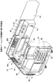
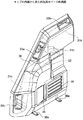
次に、図5〜図9により空調カバー22を詳細に説明する。
図5は、空調カバーおよび空調操作部の斜視図である。図5に示すように、空調カバー22は、空調ユニット21をキャブ内側から覆う内気用カバー30と、該内気用カバー30の裏面に装着される、外気導入のための外気用ダクト40とを備えている。内気用カバー30および外気用ダクト40は、合成樹脂の真空成形やプレス成形により製作されている。また、キャブ10の右側壁板51の、空調カバー22の右横部には、空調ユニット21の作動を操作するための空調操作部70が取り付けられている。空調操作部70には、電源スイッチ73と、温度調節部71と、風量調節部72と、内外気切り換えスイッチ74とが設けられている。
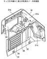
【0029】
図6および図7は、それぞれキャブ10の内側から、および外側から見た内気用カバーの斜視図である。内気用カバー30の裏面部には中空のダクトが一体成形されており、空調ユニット21の上面の送風孔29,29に対面する位置に中部ダクト31aが、内気用カバー30の上部外周部に略水平に、前記中部ダクト31aに連通する上部ダクト31bが、そして、内気用カバー30の下部外周部に、前記中部ダクト31aに連通する下部ダクト31cがそれぞれ成形されている。中部ダクト31aの、前記空調ユニット21の送風孔29,29に対面する位置には、空調されたエアを導入するための導入口32が設けられている。
【0030】
また、中部ダクト31a、上部ダクト31b、および下部ダクト31cには、それぞれ中部、上部及び下部の吹き出し孔33a,33b,33cを形成し、キャブ10の室内に連通させている。これらの吹き出し孔33a,33b,33cには、風向きの調節が可能な吹き出し部材39a,39b,39c(図5参照)がそれぞれ挿入される。
また、前記中部ダクト31aおよび上部ダクト31bに囲まれた部位には、外気用ダクト装着部34が凹状に形成されている。
【0031】
内気用カバー30の下部は、キャブ内側に向けて凸状に形成されており、その凸部に内気導入用孔(本実施例ではスリットで構成してある。)35が形成されている。また、該内気導入用孔35の左側で、前記凸部の側面に位置する部位には、該内気導入用孔35の上下方向長さよりもやや長い縦長のフィルタ交換孔36が形成され、該内気導入用孔35の裏面上下部にはフィルタガイド溝37,37が形成されている。前記フィルタ交換孔36から内気用フィルタ38が挿入され、フィルタガイド溝37,37でガイドされて内気導入用孔35の裏面側に装着される。
【0032】
内気用カバー30の下端部には取付ブラケット30aが取り付けられており、内気用カバー30はこの取付ブラケット30aを介してキャブ10のフロアプレート13に取り付けられる。
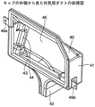
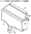
【0033】
次に、図8および図9により外気用ダクト40について詳細に説明する。図8および図9は、それぞれキャブ10の外側から、および内側から見た外気用ダクトの斜視図である。
外気用ダクト40は、箱状のフィルタ室部41と、該フィルタ室部41に連通するダクト部42とを有している。このフィルタ室部41は、キャブ10室外方に開口した外気導入口46を有し、また左右側面部の内側にフィルタ当接部43とフィルタ係止部44とを形成している。外気用フィルタ45が前記外気導入口46から挿入され、後述の図11に示すように、当接部43に当接して位置決めされ、前記フィルタ係止部44により外気用フィルタ45の左右端部に設けた係止部(図示せず)が係止されるようになっている。フィルタ室部41の左右外面部には、取付ブラケット49a,49bが設けられている。
【0034】
図5に示すように、外気用ダクト40は、その外気導入口46をキャブ10の外方へ向けた状態で前記内気用カバー30の外気用ダクト装着部34内に嵌め込まれ、外気用ダクト40の取付ブラケット49a,49bを右側壁板51に取り付ける。そして、内気用カバー30を空調ユニット21の正面から被せて、キャブ10のフロアプレート13および右側壁板51に取り付ける。なお、外気用ダクト40と内気用カバー30を、予め一体化して空調ユニット21の正面から被せる構成としてもよい。
【0035】
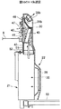
図10および図11は、それぞれ、空調装置20をキャブ外側から見た斜視図、および図10のY−Y矢視図である。
右側壁板51の、空調ユニット21に対向する部位、および外気用ダクト40の外気導入口46に対向する部位には、それぞれ取付孔55および通気孔56が形成されている。空調ユニット21は、上記取付孔55内に挿入し、そのケース21aの外側一部を右側壁板51よりも外方に突出させた状態で、右前部側板51に外側から断面L字形状のブラケット52を介してボルト53,54で取り付けられる。なお、取付孔55は、メンテナンス時に、ブラケット52をキャブ室外から取外すと、空調ユニット21及びその側面の配管接続部をキャブ内側に引き込むことができる大きさとしている。
また、通気孔56を外側から覆うように、ルーバを有する吸気カバー47がボルト48により右側壁板51に取り付けられている。前記通気孔56は、キャブ10右側に設けた作動油タンクや燃料タンク等を覆う外装カバー8よりも上方に位置するように形成している。なお、該吸気カバー47を取外すと、外気用ダクト40の外気用フィルタ45を外気導入口46から着脱可能となっている。
【0036】
次に、図4,5,7,11を参照して、上記空調装置20による、エアの吸入、吹き出し経路を説明する。
内気は、図5に示すように、内気用カバー30の内気導入用孔35および内気用フィルタ38を経由して、空調ユニット21の熱交換室23内に導入される。また、外気は、図11に示すように、吸気カバー47のルーバ、および外気用ダクト40の外気用フィルタ45、ダクト部42を経由して、空調ユニット21の外気導入室27および熱交換室23内に導入される。そして、図4に示すように、熱交換室23内で空調されたエアは送風孔29,29から送風され、図5および図7に示すように、内気用カバー30の導入口32を経由して中部ダクト31a、上部ダクト31b、および下部ダクト31cにそれぞれ送風され、さらに吹き出し部材39a,39b,39cからキャブ10の室内に吹き出される。
【0037】
図2,3に示すように、上記吹き出し部材39aから吹き出されるエアはキャブ10の前面ガラス14に向けて送風され、吹き出し部材39bから吹き出されるエアはオペレータの顔面部に向けて送風され、また吹き出し部材39cから吹き出されるエアはオペレータの足元部に向けて送風される。オペレータは操作時の姿勢に応じて、これらの吹き出し部材39a,39b,39cの風向きを手で調節する。
【0038】
なお、上記実施形態では、空調ユニットをキャブの右側壁面の前部に取り付ける構成例で説明したが、床面の右側前部に設置してもよい。この場合にも、右前方の視界性確保のために、空調装置(空調ユニットと空調カバーとを含む)の車両前側の上部を前下がりの傾斜面でカットした形状をなすように構成すればよい。また、右側壁面に開口部を設け、この開口部に嵌め込むように上記空調ユニットを床面に設置すれば、該空調ユニットはキャブの内側および外側から出し入れ可能となると共に、キャブ外に露出した部位に配管接続部を設けることもできる。さらに、右側壁面の一部を兼ねることもできるので、キャブ内スペースを広く確保することが可能となる。
【0039】
また、空調装置から吹き出すエアを前面ガラスに吹き付ける構成としたが、前面ガラスおよび側面ガラスの少なくともいずれかに吹き付けるように、空調カバーの中部ダクトに吹き出し口を設けても構わない。
さらに、本発明の適用機例として、後方超小旋回型の油圧ショベルで説明したが、これに限定されず、他の油圧ショベルにも適用可能である。
【0040】
以上の構成により、本発明は以下のような効果を奏する。
空調ユニットをキャブの右側前部の壁面又は床面に設置したため、この空調ユニットから、オペレータの足元部および顔面部、前面および側面の窓ガラスまでの距離が近くなり、これらへの配風が非常に容易となり、これらオペレータの足元部および顔面部、前面および側面の窓ガラスへエアを吹き出す吹き出し口までのダクトを非常に短くすることができ、最良の場合にはダクトを無くすこともできる。従って、ダクト布設スペースが小さいので、キャブ内の居住スペースを広く確保できる。また、これによって、ダクトの布設作業時間が短くなり、製作コストを安くできる。
【0041】
また、このとき、キャブの右側壁面の前部に該空調ユニットを取り付けることにより、空調ユニットのキャブ内側への出っ張り量が非常に少なくなるため、キャブ内の居住スペースをさらに広く確保することができる。
【0042】
また、空調ユニットを、キャブの内側および外側からの出し入れが可能なように取り付けている。上記実施形態では、右側壁面の開口部内に空調ユニットを内側または外側から嵌め込んで、この空調ユニットを断面L字形状のブラケットで右側壁面に取り付けるようにしたため、空調ユニットを取外す時には該ブラケットを外してキャブの内側または外側から引き出せるようにした。このため、車両組立時には空調ユニットを前記右側壁面の開口部内に外側から嵌め込んで取り付けることができ、また組立後のメンテナンス時には、外側からの出し入れが困難であるが、内側から出し入れすることができ、これにより組立性、整備性の向上が図れる。
【0043】
さらに、空調ユニットを、右側壁面の一部を兼ねるように、開口部内に嵌め込んで取り付けているため、空調ユニットのキャブ内への出っ張り量を少なくすることができ、これによりキャブ内スペースを広く確保することができる。また、これにより、内側および外側から空調ユニットを出し入れ可能とする構造を簡単な構成で実現できる。
【0044】
またさらに、キャブ外側に露出した空調ユニットの部位に配管接続部を設けたので、配管を通すための孔や接続部が床面や壁面に不要となり、シール箇所が少なくなってシールが容易となると共に、ガス漏れや水漏れ箇所が少なくなり信頼性を向上できる。また、空調ユニットとエンジン、ガスコンプレッサ等との間を略直線的にダイレクトに配管できるので、配管経路を短縮でき、配管作業が容易となる。
【0045】
また、空調装置(空調ユニット、空調カバーを含む)をキャブの右側前部に設けているが、この空調装置の形状は車両前側上部が前下がりの傾斜でカットされた形状を有しているため、オペレータからの車両の前部右側方向の視野が空調装置で妨げられることがなく、オペレータの右前方視界を十分に確保できる。なお、上記実施形態においては、空調ユニットと空調カバーの形状を共に上記のように構成したが、これに限定されず、例えば空調ユニットに被せる空調カバーのみを上記形状とするようにしてもよいし、または、空調カバーを被せない場合には空調ユニットのみを上記形状とするようにしてもよい。さらに、従来は、右前方視界性の低下を恐れて空調装置を設置することが無かったキャブ右側前部の位置に、空調装置を設置できるようになり、前述までの優れた効果が得られる。
【0046】
さらにまた、空調ユニットに被せる空調カバー(内装カバー)が、該空調ユニットから送風されたエアを配風するダクトを有しているため、新たにダクトを取り付ける必要が無く、ダクト布設スペースを節約してキャブ内スペースを広く確保できる。しかも、空調ユニットとダクトがこのカバーで隠れるので、見栄えを向上できる。
また、空調カバーは外気を吸入する外気用ダクトも備えているため、これらのダクトを新たに布設する必要が無く、キャブ内スペースを広く確保できる。
【0047】
また、空調ユニットへ外気を導入する導入口を、キャブの右側壁面の、外装カバーよりも上方部位に設けた。この導入口の近傍は車両略中央に位置するため、この導入口から導入するエアは塵埃の混入や、エンジン冷却後の暖まったエアによる温度上昇の影響等が少ないので、空調用として好適なエアを導入できる。これにより、外気用フィルタの寿命の向上、空調効率の向上等が図れる。
さらに、空調ユニットと該空調ユニットへ外気を導入する上記導入口との距離が近いので、外気を吸入する外気用ダクトがコンパクトになり、この外気用ダクトを装着する空調カバーをコンパクトに構成できるから、キャブ内スペースを広く確保できる。
【図面の簡単な説明】
【図1】本発明の適用機例である油圧ショベルの側面図である。
【図2】同油圧ショベルの上部旋回体の側面一部断面図である。
【図3】図2のX−X矢視図である。
【図4】空調ユニットの側面図である。
【図5】空調カバーおよび空調操作部の斜視図である。
【図6】キャブの内側から見た内気用カバーの斜視図である。
【図7】キャブの外側から見た内気用カバーの斜視図である。
【図8】キャブの外側から見た外気用ダクトの斜視図である。
【図9】キャブの内側から見た外気用ダクトの斜視図である。
【図10】空調装置をキャブ外側から見た斜視図である。
【図11】図10のY−Y矢視図である。
【符号の説明】
1…油圧ショベル、2…下部走行体、3…上部旋回体、3a…旋回フレーム、4…カウンタウエイト、5…作業機、6…スイングブラケット、7…エンジン、8…外装カバー、9…ラジエータ、10…キャブ、11…オペレータシート、12…略三角形状窓ガラス、13…フロアプレート、14…前面ガラス、15…ブラケット、16…水平ピン、20…空調装置、21…空調ユニット、21a…ケース、22…空調カバー、23…熱交換室、24…エバポレータ、25…ヒータコア、26…内気導入孔、27…外気導入室、27a…仕切り板、29…送風孔、30…内気用カバー、30a…取付ブラケット、31a…中部ダクト、31b…上部ダクト、31c…下部ダクト、32…導入口、33a,33b,33c…吹き出し孔、34…外気用ダクト装着部、35…内気導入用孔、36…フィルタ交換孔、37…フィルタガイド溝、38…内気用フィルタ、39a,39b,39c…吹き出し部材、40…外気用ダクト、41…フィルタ室部、42…ダクト部、43…フィルタ当接部、44…フィルタ係止部、45…外気用フィルタ、46…外気導入口、47…吸気カバー、48…ボルト、49a,49b…取付ブラケット、51…右側壁板、52…ブラケット、53,54…ボルト、55…取付孔、56…通気孔、61,62…温水管、63,64…冷媒ガス管、70…空調操作部、71…温度調節部、72…風量調節部、73…電源スイッチ、74…内外気切り換えスイッチ。[0001]
TECHNICAL FIELD OF THE INVENTION
The present invention relates to an air conditioner installed in a cab of a hydraulic excavator.
[0002]
[Prior art]
Some construction machines, such as hydraulic excavators, include a cab provided with a working machine operating device and a traveling control device in a room surrounded by a driver's seat by a wall having a door for getting on and off and a window having a window. In recent years, an air conditioner (hereinafter, referred to as an air conditioner) for improving operability (e.g., defroster of window glass) and improving comfort (cooling, heating, and air conditioning) has been widely used. 2. Description of the Related Art Conventionally, this air conditioner has, for the purpose of securing a large space in a cab and ensuring visibility of an operator, for example, between an operator seat and a rear wall surface of a cab (for example, see Patent Document 1), and a cab. It is installed on a rear wall portion, a floor surface below an operator seat (for example, see Patent Document 2), or a cab ceiling surface (for example, see Patent Document 3).
[0003]
[Patent Document 1]
JP-A-8-183323 (page 3, FIG. 1)
[Patent Document 2]
JP 2001-55760 A (page 4, FIG. 2, 4)
[Patent Document 3]
JP-A-53-52549 (pages 3-5, FIG. 1-4)
[0004]
[Problems to be solved by the invention]
However, the conventional air conditioner has the following problems.
In order to guide the air blown out of the air conditioner to the outlet near the operator's feet and face, and to the defroster outlet near the front and / or side window glass, the air conditioner and the various outlets are provided. It is necessary to lay a ventilation duct connecting the mouth. However, when this is laid in the cab, there is a problem that the space in the cab is narrowed by the duct space. In addition, the duct connecting the air conditioner and the specific outlet becomes longer, and in the example described in
[0005]
SUMMARY OF THE INVENTION The present invention has been made in view of the above problems, and provides an air conditioner for a hydraulic shovel that can secure a wide space in a cab and can easily lay ducts for arranging air at various points in the cab. It is intended to be.
[0006]
Means for Solving the Problems, Functions and Effects
In order to achieve the above object, a first aspect of the present invention is an air conditioner installed in a cab of a hydraulic shovel, in which an air conditioning unit is installed in a right front portion inside the cab.
[0007]
According to the first invention, since the air conditioning unit is installed at the right front portion in the cab, which is a position close to both the face and the feet of the operator and the front and side window glasses, a long duct or the like is laid. Without having to do so, it is very easy to distribute the air to the face and feet, the front and / or side windows of the operator. Therefore, the duct laying time is shortened, the production cost can be reduced, and the space in the cab can be widened because the duct space is reduced.
[0008]
A second aspect of the present invention is an air conditioner installed in a cab of a hydraulic excavator, wherein an air conditioning unit is attached to a front portion of a right side wall surface of the cab.
[0009]
According to the second invention, since the air conditioning unit is attached to the front portion of the right side wall surface of the cab, which is a position close to both the face portion and the foot portion of the operator and the front and side window glasses, a long duct or the like is laid. This makes it very easy to distribute air to the operator's face and feet, front and / or side windows. Therefore, the duct installation work time is shortened, and the manufacturing cost can be reduced. In addition, the duct space is reduced, and the air-conditioning unit is mounted on the wall surface, so that a large space in the cab can be secured.
[0010]
In a third aspect based on the first or second aspect, the air conditioning unit is mounted on the right wall surface so as to be able to be taken in and out from the inside and outside of the cab.
[0011]
According to the third invention, since the air conditioning unit is attached so as to be able to be taken in and out from the inside and outside of the cab, it can be attached to the right side wall from outside when assembling the vehicle with the cab alone, and taken out from inside the cab during maintenance or the like after mounting the vehicle. Can be installed. Thereby, workability at the time of assembly and maintenance can be improved.
[0012]
In a fourth aspect based on the third aspect, the air conditioning unit is configured to be mounted so as to also serve as a part of a right wall surface.
[0013]
According to the fourth aspect, since the air-conditioning unit is mounted also as a part of the right wall surface, the amount of protrusion of the air-conditioning unit into the cab is reduced, and a large space in the cab can be secured. In addition, this makes it possible to simplify the structure according to the third invention for mounting the air conditioning unit so that it can be taken in and out from the inside and outside of the cab.
[0014]
In a fifth aspect based on the first, second or third aspect, the pipe connection portion of the air conditioning unit is provided at a portion exposed outside the cab.
[0015]
According to the fifth aspect of the present invention, the piping for the hot water and the refrigerant gas to the air conditioning unit can be connected to the piping connection portion provided at a portion exposed to the outside of the cab, so that the hole for passing the piping through the side wall surface or the floor surface of the cab. And the need for connecting parts are eliminated, thereby reducing the number of pipe seal locations and facilitating sealing, and reducing gas leaks and water leaks, thereby improving reliability. In addition, since the piping between the air conditioning unit and the radiator, the gas compressor, or the like can be directly piped substantially linearly, the piping path can be shortened, and the piping work becomes easy.
[0016]
A sixth aspect of the present invention is the air conditioner according to the first or second aspect, wherein the upper portion on the front side of the vehicle has a shape cut by a downward slope.
[0017]
According to the sixth aspect, the air conditioner (including the air conditioner unit and the interior cover that covers the air conditioner unit) has a shape in which the upper part on the front side of the vehicle is cut at a downward slant. The visual field in the front right direction of the vehicle is not obstructed by the air conditioner, and the operator's right front view can be sufficiently ensured. Further, the air conditioner can be installed at the position on the right front portion of the cab where the air conditioner has not been conventionally installed due to fear of a decrease in right front visibility, and the above-described excellent effects can be obtained.
[0018]
According to a seventh aspect of the present invention, in the first or second aspect, a duct for distributing air blown from the air conditioning unit in a predetermined direction is provided on an interior cover that covers the air conditioning unit.
[0019]
According to the seventh aspect, since the interior cover over the air-conditioning unit has the duct for distributing the air blown from the air-conditioning unit, it is not necessary to newly install a duct, and the duct installation space can be saved. The space inside the cab can be secured widely. Moreover, since the air conditioning unit and the duct are hidden by this cover, the appearance can be improved.
[0020]
According to an eighth aspect of the present invention, in an air conditioner installed in a cab of a hydraulic shovel, an inlet for introducing outside air to the air conditioning unit is provided on a right side wall surface of the cab above the outer cover.
[0021]
According to the eighth aspect, the vicinity of the inlet provided on the right side wall surface of the cab above the outer cover is located substantially at the center of the vehicle, so that the air introduced from this inlet is contaminated with dust and the engine cooling. Since the influence of the temperature rise due to the warmed air later is small, air suitable for air conditioning can be introduced. As a result, the life of the outside air filter can be improved, the air conditioning efficiency can be improved, and the like.
[0022]
BEST MODE FOR CARRYING OUT THE INVENTION
Hereinafter, embodiments of the present invention will be described in detail with reference to the drawings.
[0023]
First, with reference to FIGS. 1 to 3, a schematic configuration of a rear-small turning type hydraulic excavator which is an example of an application machine of the present invention will be described. FIG. 1 is a side view of a hydraulic shovel as an example of an application machine of the present invention, FIG. 2 is a partial cross-sectional side view of an upper swing body of the hydraulic shovel, and FIG. It is.
[0024]
In these figures, a
[0025]
An
[0026]
Next, the configuration of the
4, in the
[0027]
A blower (not shown) is provided above the
[0028]
Next, the
FIG. 5 is a perspective view of the air conditioning cover and the air conditioning operation unit. As shown in FIG. 5, the air-
[0029]
6 and 7 are perspective views of the inside air cover viewed from inside and outside of the
[0030]
The middle, upper, and
An outside air
[0031]
The lower portion of the
[0032]
A mounting
[0033]
Next, the
The
[0034]
As shown in FIG. 5, the
[0035]
10 and 11 are a perspective view of the
At the portion of the right
An intake cover 47 having a louver is attached to the right
[0036]
Next, with reference to FIGS.
As shown in FIG. 5, the inside air is introduced into the
[0037]
As shown in FIGS. 2 and 3, the air blown out from the
[0038]
In the above embodiment, the configuration example in which the air conditioning unit is attached to the front portion of the right side wall surface of the cab has been described. However, the air conditioning unit may be installed at the right front portion of the floor surface. Also in this case, in order to ensure the visibility of the right front, the upper part of the air conditioner (including the air conditioner unit and the air conditioner cover) on the front side of the vehicle may be formed to have a shape cut by a downwardly inclined surface. . Also, if an opening is provided on the right side wall surface and the air conditioning unit is installed on the floor so as to fit into the opening, the air conditioning unit can be put in and out from the inside and outside of the cab, and is exposed outside the cab. A pipe connection may be provided at the site. Furthermore, since it can also serve as a part of the right side wall surface, it is possible to secure a large space in the cab.
[0039]
Although the air blown from the air conditioner is blown to the front glass, a blow port may be provided in the middle duct of the air conditioning cover so as to blow at least one of the front glass and the side glass.
Furthermore, as an example of the application machine of the present invention, the description has been made of the hydraulic excavator of the ultra-small back swing type.
[0040]
With the above configuration, the present invention has the following effects.
Since the air conditioning unit was installed on the wall or floor at the front right side of the cab, the distance from this air conditioning unit to the operator's feet and face, the front and side windows, and the air distribution to these units was extremely low. The length of the duct to the outlets that blow air to the window glass on the feet and face, front and side windows of the operator can be made very short, and in the best case, the duct can be eliminated. Therefore, since the duct installation space is small, a large living space in the cab can be secured. In addition, as a result, the work for laying the duct is shortened, and the production cost can be reduced.
[0041]
Also, at this time, by attaching the air conditioning unit to the front portion of the right side wall surface of the cab, the amount of protrusion of the air conditioning unit to the inside of the cab becomes very small, so that a larger living space in the cab can be secured. .
[0042]
In addition, the air conditioning unit is mounted so that it can be taken in and out from the inside and outside of the cab. In the above embodiment, the air conditioning unit is fitted into the opening of the right wall surface from the inside or the outside, and the air conditioning unit is attached to the right wall surface with a bracket having an L-shaped cross section. To be pulled out from the inside or outside of the cab. For this reason, at the time of assembling the vehicle, the air-conditioning unit can be fitted into the opening of the right wall surface from the outside, and can be installed and removed from the outside during maintenance after assembly. Thereby, assemblability and maintainability can be improved.
[0043]
Furthermore, since the air conditioning unit is fitted into the opening so as to also serve as a part of the right side wall, the amount of protrusion of the air conditioning unit into the cab can be reduced, thereby increasing the space inside the cab. Can be secured. In addition, a structure that allows the air conditioning unit to be taken in and out from the inside and outside can be realized with a simple configuration.
[0044]
Further, since a pipe connection portion is provided at a portion of the air conditioning unit exposed to the outside of the cab, holes and connection portions for passing the pipe are not required on the floor surface or the wall surface, and the number of sealing points is reduced and sealing is facilitated. At the same time, gas leaks and water leaks are reduced, and reliability can be improved. In addition, since piping between the air conditioning unit and the engine, gas compressor, or the like can be directly piped substantially linearly, the piping path can be shortened, and piping work becomes easy.
[0045]
An air conditioner (including an air conditioner unit and an air conditioner cover) is provided at the front right side of the cab. However, the shape of this air conditioner has a shape in which the upper part on the front side of the vehicle is cut with a downward slope. Thus, the field of view of the operator in the front right direction of the vehicle is not obstructed by the air conditioner, and the operator's right front view can be sufficiently ensured. In the above embodiment, both the air-conditioning unit and the air-conditioning cover are configured as described above. However, the present invention is not limited to this. For example, only the air-conditioning cover that covers the air-conditioning unit may have the above-described shape. Alternatively, when the air conditioning cover is not covered, only the air conditioning unit may have the above shape. Further, the air conditioner can be installed at the position on the right front portion of the cab where the air conditioner has not been installed in the related art because of the fear of a decrease in the right front visibility, and the above-described excellent effects can be obtained.
[0046]
Furthermore, since the air-conditioning cover (interior cover) that covers the air-conditioning unit has a duct for distributing the air blown from the air-conditioning unit, there is no need to newly install a duct, and the duct installation space can be saved. The space inside the cab can be secured widely. Moreover, since the air conditioning unit and the duct are hidden by this cover, the appearance can be improved.
Further, since the air-conditioning cover also has an outside air duct for sucking outside air, there is no need to newly lay these ducts, and a wide space in the cab can be secured.
[0047]
In addition, an inlet for introducing outside air to the air conditioning unit is provided on the right side wall surface of the cab above the outer cover. Since the vicinity of this inlet is located substantially at the center of the vehicle, the air introduced from this inlet is less affected by dust and the rise in temperature due to warm air after cooling the engine. Can be introduced. As a result, the life of the outside air filter can be improved, the air conditioning efficiency can be improved, and the like.
Further, since the distance between the air conditioning unit and the inlet for introducing outside air to the air conditioning unit is short, the outside air duct for sucking outside air is compact, and the air conditioning cover to which the outside air duct is attached can be made compact. , The space inside the cab can be secured widely.
[Brief description of the drawings]
FIG. 1 is a side view of a hydraulic excavator that is an example of an application machine of the present invention.
FIG. 2 is a partial cross-sectional side view of the upper swing body of the hydraulic excavator.
FIG. 3 is a view as viewed in the direction of arrows XX in FIG. 2;
FIG. 4 is a side view of the air conditioning unit.
FIG. 5 is a perspective view of an air conditioning cover and an air conditioning operation unit.
FIG. 6 is a perspective view of the inside air cover viewed from the inside of the cab.
FIG. 7 is a perspective view of the inside air cover as viewed from the outside of the cab.
FIG. 8 is a perspective view of the outside air duct viewed from the outside of the cab.
FIG. 9 is a perspective view of the outside air duct viewed from the inside of the cab.
FIG. 10 is a perspective view of the air conditioner as viewed from the outside of the cab.
FIG. 11 is a view taken in the direction of arrows YY in FIG. 10;
[Explanation of symbols]
DESCRIPTION OF
Claims (8)
キャブ(10)内の右側前部に、空調ユニット(21)を設置した
ことを特徴とする油圧ショベルの空調装置。In an air conditioner installed in a cab (10) of a hydraulic excavator,
An air conditioner for a hydraulic shovel, wherein an air conditioning unit (21) is installed at a right front portion inside the cab (10).
キャブ(10)の右側壁面(51)の前部に、空調ユニット(21)を取り付けた
ことを特徴とする油圧ショベルの空調装置。In an air conditioner installed in a cab (10) of a hydraulic excavator,
An air conditioner for a hydraulic shovel, wherein an air conditioning unit (21) is attached to a front portion of a right side wall (51) of a cab (10).
前記空調ユニット(21)は、キャブ(10)の内側および外側から出し入れ可能に、右側壁面(51)に取り付けられた
ことを特徴とする油圧ショベルの空調装置。The air conditioner for a hydraulic shovel according to claim 1 or 2,
The air conditioner for a hydraulic shovel, wherein the air conditioning unit (21) is attached to a right wall surface (51) so as to be able to be taken in and out of the cab (10).
前記空調ユニット(21)は、右側壁面(51)の一部を兼ねて取り付けられた
ことを特徴とする油圧ショベルの空調装置。The air conditioner for a hydraulic shovel according to claim 3,
The air conditioner for a hydraulic shovel, wherein the air conditioning unit (21) is mounted so as to also serve as a part of a right wall surface (51).
前記空調ユニット(21)の配管接続部(61,62,63,64)は、キャブ(10)外側に露出した部位に設けた
ことを特徴とする油圧ショベルの空調装置。The air conditioner for a hydraulic shovel according to claim 1, 2 or 3,
An air conditioner for a hydraulic shovel, wherein a pipe connection portion (61, 62, 63, 64) of the air conditioning unit (21) is provided at a portion exposed outside the cab (10).
車両前側上部が前下がりの傾斜でカットされた形状を有する
ことを特徴とする油圧ショベルの空調装置。The air conditioner for a hydraulic shovel according to claim 1 or 2,
An air conditioner for a hydraulic shovel, wherein an upper portion of a front side of a vehicle has a shape cut by a downward slope.
前記空調ユニット(21)に被せる内装カバー(30)に、該空調ユニット(21)から送風されたエアを配風するダクト(31a,31b,31c)を設けた
ことを特徴とする油圧ショベルの空調装置。The air conditioner for a hydraulic shovel according to claim 1 or 2,
A duct (31a, 31b, 31c) for distributing air blown from the air conditioning unit (21) is provided on an interior cover (30) covering the air conditioning unit (21). apparatus.
空調ユニット(21)へ外気を導入する導入口(56)は、キャブ(10)の右側壁面(51)の、外装カバー(8)よりも上方部位に設けた
ことを特徴とする油圧ショベルの空調装置。In an air conditioner installed in a cab (10) of a hydraulic excavator,
An air inlet (56) for introducing outside air to the air conditioning unit (21) is provided on the right side wall (51) of the cab (10) above the exterior cover (8). apparatus.
Priority Applications (5)
| Application Number | Priority Date | Filing Date | Title |
|---|---|---|---|
| JP2003102159A JP4261962B2 (en) | 2003-04-04 | 2003-04-04 | Hydraulic excavator air conditioner |
| CNB2004100397972A CN1309911C (en) | 2003-04-04 | 2004-03-17 | Air conditoning device of oil pressure digger |
| US10/805,619 US7069736B2 (en) | 2003-04-04 | 2004-03-18 | Air conditioning apparatus for hydraulic shovel |
| DE602004000049T DE602004000049T2 (en) | 2003-04-04 | 2004-03-23 | Air conditioning for hydraulic excavators |
| EP04006946A EP1464522B1 (en) | 2003-04-04 | 2004-03-23 | Air conditioning apparatus for hydraulic shovel |
Applications Claiming Priority (1)
| Application Number | Priority Date | Filing Date | Title |
|---|---|---|---|
| JP2003102159A JP4261962B2 (en) | 2003-04-04 | 2003-04-04 | Hydraulic excavator air conditioner |
Related Child Applications (1)
| Application Number | Title | Priority Date | Filing Date |
|---|---|---|---|
| JP2008222686A Division JP4909960B2 (en) | 2008-08-29 | 2008-08-29 | Hydraulic excavator air conditioner |
Publications (2)
| Publication Number | Publication Date |
|---|---|
| JP2004306754A true JP2004306754A (en) | 2004-11-04 |
| JP4261962B2 JP4261962B2 (en) | 2009-05-13 |
Family
ID=32844725
Family Applications (1)
| Application Number | Title | Priority Date | Filing Date |
|---|---|---|---|
| JP2003102159A Expired - Fee Related JP4261962B2 (en) | 2003-04-04 | 2003-04-04 | Hydraulic excavator air conditioner |
Country Status (5)
| Country | Link |
|---|---|
| US (1) | US7069736B2 (en) |
| EP (1) | EP1464522B1 (en) |
| JP (1) | JP4261962B2 (en) |
| CN (1) | CN1309911C (en) |
| DE (1) | DE602004000049T2 (en) |
Cited By (9)
| Publication number | Priority date | Publication date | Assignee | Title |
|---|---|---|---|---|
| JP2007245894A (en) * | 2006-03-15 | 2007-09-27 | Shin Caterpillar Mitsubishi Ltd | Operating machine |
| JP2007308029A (en) * | 2006-05-18 | 2007-11-29 | Kubota Corp | Work vehicle operating structure |
| WO2009028306A1 (en) * | 2007-08-24 | 2009-03-05 | Yanmar Co., Ltd. | Rotation type working vehicle |
| JP2009097526A (en) * | 2007-10-12 | 2009-05-07 | Komatsu Ltd | Bolt fastening structure and construction machinery |
| JP2009215699A (en) * | 2008-03-06 | 2009-09-24 | Yanmar Co Ltd | Revolving working vehicle |
| JP2013248997A (en) * | 2012-05-31 | 2013-12-12 | Yanmar Co Ltd | Air condition duct structure of working vehicle |
| JP2016070002A (en) * | 2014-09-30 | 2016-05-09 | 株式会社クボタ | Cabin of work machine and work machine provided with the same |
| JP2016145491A (en) * | 2015-02-09 | 2016-08-12 | 日立建機株式会社 | Construction machine |
| JP2022153906A (en) * | 2021-03-30 | 2022-10-13 | コベルコ建機株式会社 | Construction machine |
Families Citing this family (20)
| Publication number | Priority date | Publication date | Assignee | Title |
|---|---|---|---|---|
| GB2466766A (en) * | 2008-10-27 | 2010-07-07 | Agco Gmbh | Tractor cab with cavity floor for HVAC unit and ducting |
| WO2012035945A1 (en) * | 2010-09-17 | 2012-03-22 | 株式会社クボタ | Combine harvester |
| JP5612134B2 (en) * | 2011-02-07 | 2014-10-22 | 日立建機株式会社 | Construction machinery |
| AU2012200739B2 (en) | 2011-02-10 | 2014-11-06 | Joy Global Underground Mining Llc | Enclosed cab system for mining equipment |
| US8985263B2 (en) | 2011-03-01 | 2015-03-24 | Joy Mm Delaware, Inc. | Seat module for a mining vehicle |
| JP5546484B2 (en) * | 2011-03-17 | 2014-07-09 | 日立建機株式会社 | Mini excavator fuel tank fixing structure |
| CN102501742A (en) * | 2011-11-22 | 2012-06-20 | 湖南瑞龙重工科技有限公司 | Air conditioner for cab |
| USD664998S1 (en) | 2011-12-01 | 2012-08-07 | Harnischfeger Technologies, Inc. | Seat module |
| USD667851S1 (en) | 2011-12-01 | 2012-09-25 | Harnischfeger Technologies, Inc. | Cab module |
| AU2012258458B9 (en) | 2011-12-01 | 2014-11-06 | Joy Global Surface Mining Inc | Cab module for a mining machine |
| JP2013249647A (en) * | 2012-05-31 | 2013-12-12 | Yanmar Co Ltd | Body structure of work vehicle |
| CN103255797B (en) * | 2013-05-13 | 2015-09-02 | 柳州柳工挖掘机有限公司 | Mini-excavator |
| WO2015088080A1 (en) * | 2013-12-13 | 2015-06-18 | 볼보 컨스트럭션 이큅먼트 에이비 | Cabin for construction machine |
| WO2018029821A1 (en) * | 2016-08-10 | 2018-02-15 | 株式会社小松製作所 | Work vehicle and cabin unit |
| US10543733B2 (en) * | 2016-11-14 | 2020-01-28 | Cnh Industrial America Llc | Heating, ventilation, and air conditioning system of a work vehicle |
| CN107176011A (en) * | 2017-06-27 | 2017-09-19 | 徐州徐工矿山机械有限公司 | Articulated truck driver's cabin pressure charging system |
| JP7131173B2 (en) * | 2018-07-27 | 2022-09-06 | コベルコ建機株式会社 | Construction machine cab |
| CN112227437A (en) * | 2020-10-20 | 2021-01-15 | 中联重科股份有限公司 | Skid Steer Cab and Skid Steer Loader |
| CN112554252A (en) * | 2021-01-07 | 2021-03-26 | 徐工集团工程机械股份有限公司科技分公司 | Basement operating mode low type loader |
| CN113638461A (en) * | 2021-08-26 | 2021-11-12 | 江苏徐工工程机械研究院有限公司 | An interior layout method and control system in a narrow space |
Family Cites Families (17)
| Publication number | Priority date | Publication date | Assignee | Title |
|---|---|---|---|---|
| US2052471A (en) * | 1935-05-14 | 1936-08-25 | Hula Roger | Agricultural and industrial cab for tractors and similar machinery |
| US3841108A (en) * | 1973-12-17 | 1974-10-15 | Automatic Radio Mfg Co | Power-refrigeration apparatus for recreational vehicles and the like |
| US4133574A (en) * | 1976-10-26 | 1979-01-09 | Martin Robert P | Guard-cab for cold room |
| JPS5352549A (en) | 1976-10-26 | 1978-05-13 | Nippon Steel Corp | Method for wiping liquid materials from continous strips |
| US4344356A (en) * | 1980-06-23 | 1982-08-17 | Deere & Company | Air distribution system |
| DE4001148A1 (en) * | 1990-01-17 | 1991-07-18 | Deere & Co | Feeding external air into tractor cabin via conduits - incorporating filter elements readily accessible from exterior |
| JPH0458408U (en) * | 1990-09-27 | 1992-05-19 | ||
| JPH08183323A (en) | 1994-12-28 | 1996-07-16 | Komatsu Ltd | Air conditioner for construction machinery |
| JP3482301B2 (en) * | 1996-05-27 | 2003-12-22 | コベルコ建機株式会社 | Air conditioner for construction machinery |
| US5826440A (en) * | 1996-05-30 | 1998-10-27 | Kabushiki Kaisha Kobe Seiko Sho | Construction machine |
| US6126539A (en) * | 1998-10-01 | 2000-10-03 | Caterpillar S.A.R.L. | Pilot valve mounting which functions as a hot air duct |
| JP3604933B2 (en) * | 1998-12-21 | 2004-12-22 | 日立建機株式会社 | Cab for construction machinery |
| JP3702991B2 (en) * | 1998-12-25 | 2005-10-05 | コベルコ建機株式会社 | Construction machinery cab |
| JP3418361B2 (en) | 1999-08-19 | 2003-06-23 | 株式会社小松製作所 | Installation structure of the cab air conditioner of the work vehicle |
| US6129056A (en) * | 1999-08-23 | 2000-10-10 | Case Corporation | Cooling system for work vehicle |
| JP2002121770A (en) * | 2000-10-13 | 2002-04-26 | Hitachi Constr Mach Co Ltd | Cab for construction machine |
| JP2002220032A (en) * | 2001-01-24 | 2002-08-06 | Hitachi Constr Mach Co Ltd | Water collecting device for window washer liquid |
-
2003
- 2003-04-04 JP JP2003102159A patent/JP4261962B2/en not_active Expired - Fee Related
-
2004
- 2004-03-17 CN CNB2004100397972A patent/CN1309911C/en not_active Expired - Fee Related
- 2004-03-18 US US10/805,619 patent/US7069736B2/en not_active Expired - Fee Related
- 2004-03-23 EP EP04006946A patent/EP1464522B1/en not_active Expired - Lifetime
- 2004-03-23 DE DE602004000049T patent/DE602004000049T2/en not_active Expired - Lifetime
Cited By (11)
| Publication number | Priority date | Publication date | Assignee | Title |
|---|---|---|---|---|
| JP2007245894A (en) * | 2006-03-15 | 2007-09-27 | Shin Caterpillar Mitsubishi Ltd | Operating machine |
| JP2007308029A (en) * | 2006-05-18 | 2007-11-29 | Kubota Corp | Work vehicle operating structure |
| WO2009028306A1 (en) * | 2007-08-24 | 2009-03-05 | Yanmar Co., Ltd. | Rotation type working vehicle |
| JP2009051299A (en) * | 2007-08-24 | 2009-03-12 | Yanmar Co Ltd | Swivel work vehicle |
| JP2009097526A (en) * | 2007-10-12 | 2009-05-07 | Komatsu Ltd | Bolt fastening structure and construction machinery |
| JP2009215699A (en) * | 2008-03-06 | 2009-09-24 | Yanmar Co Ltd | Revolving working vehicle |
| JP2013248997A (en) * | 2012-05-31 | 2013-12-12 | Yanmar Co Ltd | Air condition duct structure of working vehicle |
| JP2016070002A (en) * | 2014-09-30 | 2016-05-09 | 株式会社クボタ | Cabin of work machine and work machine provided with the same |
| JP2016145491A (en) * | 2015-02-09 | 2016-08-12 | 日立建機株式会社 | Construction machine |
| JP2022153906A (en) * | 2021-03-30 | 2022-10-13 | コベルコ建機株式会社 | Construction machine |
| JP7537339B2 (en) | 2021-03-30 | 2024-08-21 | コベルコ建機株式会社 | Construction Machinery |
Also Published As
| Publication number | Publication date |
|---|---|
| CN1536177A (en) | 2004-10-13 |
| US7069736B2 (en) | 2006-07-04 |
| JP4261962B2 (en) | 2009-05-13 |
| EP1464522B1 (en) | 2005-08-10 |
| CN1309911C (en) | 2007-04-11 |
| DE602004000049T2 (en) | 2006-06-08 |
| US20040194488A1 (en) | 2004-10-07 |
| DE602004000049D1 (en) | 2005-09-15 |
| EP1464522A1 (en) | 2004-10-06 |
Similar Documents
| Publication | Publication Date | Title |
|---|---|---|
| JP4261962B2 (en) | Hydraulic excavator air conditioner | |
| KR101478851B1 (en) | Construction machine | |
| CN100465010C (en) | Cockpit of work vehicle | |
| KR100602965B1 (en) | Work vehicle | |
| JP4909960B2 (en) | Hydraulic excavator air conditioner | |
| CN1545456A (en) | Air conditioner on construction machinery | |
| JP4443485B2 (en) | Air conditioning structure for cabin of work vehicle | |
| JPS641133Y2 (en) | ||
| JP4184549B2 (en) | Air conditioning equipment for construction machinery | |
| JPS641845Y2 (en) | ||
| JP4960998B2 (en) | Air conditioning structure for cabin of work vehicle | |
| JP2009255919A (en) | Air-conditioning structure for cabin of work vehicle | |
| JP4443486B2 (en) | Air conditioning structure for cabin of work vehicle | |
| JP4226521B2 (en) | cabin | |
| JP4541989B2 (en) | Construction machinery | |
| JP2009255920A5 (en) | ||
| JP2004268799A (en) | Work vehicle air conditioner | |
| JP2009255919A5 (en) | ||
| JP2006218908A (en) | Air conditioner for cabin of work machine vehicle | |
| JPH11334351A (en) | Cab equipped with air conditioner for construction machine | |
| JP4528227B2 (en) | Air conditioning structure for cabin of agricultural tractor | |
| JP5188332B2 (en) | Work vehicle | |
| JPH11343636A (en) | Backhoe cooling system | |
| JP3621165B2 (en) | Air conditioning mechanism for vehicles with cabins | |
| JP2004268801A (en) | Work vehicle |
Legal Events
| Date | Code | Title | Description |
|---|---|---|---|
| A621 | Written request for application examination |
Free format text: JAPANESE INTERMEDIATE CODE: A621 Effective date: 20051118 |
|
| A977 | Report on retrieval |
Free format text: JAPANESE INTERMEDIATE CODE: A971007 Effective date: 20080424 |
|
| A131 | Notification of reasons for refusal |
Free format text: JAPANESE INTERMEDIATE CODE: A131 Effective date: 20080702 |
|
| A521 | Request for written amendment filed |
Free format text: JAPANESE INTERMEDIATE CODE: A523 Effective date: 20080829 |
|
| RD02 | Notification of acceptance of power of attorney |
Free format text: JAPANESE INTERMEDIATE CODE: A7422 Effective date: 20080829 |
|
| TRDD | Decision of grant or rejection written | ||
| A01 | Written decision to grant a patent or to grant a registration (utility model) |
Free format text: JAPANESE INTERMEDIATE CODE: A01 Effective date: 20090203 |
|
| A01 | Written decision to grant a patent or to grant a registration (utility model) |
Free format text: JAPANESE INTERMEDIATE CODE: A01 |
|
| A61 | First payment of annual fees (during grant procedure) |
Free format text: JAPANESE INTERMEDIATE CODE: A61 Effective date: 20090206 |
|
| FPAY | Renewal fee payment (event date is renewal date of database) |
Free format text: PAYMENT UNTIL: 20120220 Year of fee payment: 3 |
|
| R150 | Certificate of patent or registration of utility model |
Ref document number: 4261962 Country of ref document: JP Free format text: JAPANESE INTERMEDIATE CODE: R150 Free format text: JAPANESE INTERMEDIATE CODE: R150 |
|
| FPAY | Renewal fee payment (event date is renewal date of database) |
Free format text: PAYMENT UNTIL: 20130220 Year of fee payment: 4 |
|
| FPAY | Renewal fee payment (event date is renewal date of database) |
Free format text: PAYMENT UNTIL: 20140220 Year of fee payment: 5 |
|
| LAPS | Cancellation because of no payment of annual fees |