JP2004306865A - Sliding control device for railway vehicles - Google Patents
Sliding control device for railway vehicles Download PDFInfo
- Publication number
- JP2004306865A JP2004306865A JP2003105596A JP2003105596A JP2004306865A JP 2004306865 A JP2004306865 A JP 2004306865A JP 2003105596 A JP2003105596 A JP 2003105596A JP 2003105596 A JP2003105596 A JP 2003105596A JP 2004306865 A JP2004306865 A JP 2004306865A
- Authority
- JP
- Japan
- Prior art keywords
- sliding
- braking force
- railway vehicle
- axle
- control device
- Prior art date
- Legal status (The legal status is an assumption and is not a legal conclusion. Google has not performed a legal analysis and makes no representation as to the accuracy of the status listed.)
- Granted
Links
Images



Landscapes
- Regulating Braking Force (AREA)
Abstract
【課題】ブレーキ作用時で車輪滑走発生時、非滑走軸に滑走を誘発しないようにより適切にブレーキ力を増減させ、車輪滑走を抑制する鉄道車両用滑走制御装置を提供する。
【解決手段】走行する鉄道車両のブレーキ作用時に発生する車輪滑走を抑制する鉄道車両用滑走制御装置であって、各車軸の回転速度に基づき滑走を判定する滑走判断手段1〜5と、この滑走判断手段の判定に基づき、滑走軸の滑走回数に応じて、非滑走軸のブレーキ力を増加させるように各車軸のブレーキ力を制御する信号を発生する滑走量・ブレーキ力増減量判定手段80と、を備えた。
【選択図】 図1A sliding control device for a railway vehicle that suppresses wheel sliding by appropriately increasing or decreasing a braking force so as not to induce sliding on a non-sliding axis when wheel sliding occurs during braking action.
Kind Code: A1 Abstract: A sliding control device for a railway vehicle, which suppresses the sliding of wheels generated when a running railway vehicle brakes, comprising: sliding determining means for determining sliding based on the rotational speed of each axle; A glide amount / brake force increase / decrease amount determination means for generating a signal for controlling the braking force of each axle so as to increase the braking force of the non-sliding axis in accordance with the number of times of the sliding axis based on the determination by the determination means; , With.
[Selection diagram] Fig. 1
Description
【0001】
【発明の属する技術分野】
この発明は、電気車両において、ブレーキ作用中における車輪の滑走を検出してブレーキ力を制御する鉄道車両用滑走制御装置に関するものである。
【0002】
【従来の技術】
図5は従来の鉄道車両用滑走制御装置の構成を示すブロック図である。図5において、1a〜1dは速度センサ、2は速度入力部、3は速度差検出部、4は加減速度検出部、5は滑走発生を判断する判断部、8は滑走量判定部、6は出力部、7は滑走防止弁である。
【0003】
速度入力部2は、1車両2台車の4車軸に設けられそれぞれの車軸の回転速度を検出する速度センサ1a、1b、1c、1dからの信号を入力する。速度差検出部3は、4車軸の速度の内で最大軸を基準軸速度(滑走を生じていない車軸の速度に相当する)としてこの基準軸速度と各車軸の速度との差を検出する。加減速度検出部4は、各速度センサ1からの速度信号を微分して加減速度を検出する。判断部5は、両検出部3,4の出力が予め設定した設定値を越えた時に滑走発生と判断する。滑走量判定部8は、判断部5より滑走と判断した時の滑走量を算出する。出力部6は、判定結果に基づき滑走した車輪の滑走防止弁7を制御する。
【0004】
ここで、滑走防止弁7は滑走の状態に応じて圧縮空気をブレーキシリンダから排気してブレーキシリンダ圧を低下させたり、その後のブレーキシリンダ圧を保持したり、あるいは、再び、圧縮空気をブレーキシリンダに供給してブレーキシリンダ圧を高めたりすることにより滑走車輪を再粘着させる。
【0005】
【発明が解決しようとする課題】
従来の鉄道車両用滑走制御装置は上記のように構成されているので、雨天で車輪−レール間が低粘着状態により、滑走が発生している場合を想定すると、前・後台車の軸重移動を考慮していないために、ブレーキ作用時、進行方向の台車に軸重が移動するので、非滑走軸に滑走を誘発することになり、また、車輪滑走時においても非滑走軸の滑走を誘発するという問題点があった。
【0006】
この発明は上記のような問題点を解消するためになされたもので、ブレーキ作用時で車輪滑走発生時、非滑走軸に滑走を誘発しないようにより適切にブレーキ力を増減させ、車輪滑走を抑制する鉄道車両用滑走制御装置を提供することを目的とする。
【0007】
【課題を解決するための手段】
上記の目的に鑑み、この発明は、走行する鉄道車両のブレーキ作用時に発生する車輪滑走を抑制する鉄道車両用滑走制御装置であって、各車軸の回転速度に基づき滑走を判定する滑走判断手段と、この滑走判断手段の判定に基づき、滑走軸の滑走回数に応じて、非滑走軸のブレーキ力を増加させるように各車軸のブレーキ力を制御する信号を発生する滑走量・ブレーキ力増減量判定手段と、を備えたことを特徴とする鉄道車両用滑走制御装置にある。
【0008】
また、走行する鉄道車両のブレーキ作用時に発生する車輪滑走を抑制する鉄道車両用滑走制御装置であって、各車軸の回転速度に基づき滑走を判定する滑走判断手段と、各車軸でのブレーキ力増加を示す信号を入力すると共に前記滑走判断手段の判定に基づき、ブレーキ作用時に軸重の増加する非滑走軸のブレーキ力の増加量に応じて、軸重の軽減される滑走軸のブレーキ力を低減するように各車軸のブレーキ力を制御する信号を発生する滑走量・ブレーキ力増減量判定手段と、を備えたことを特徴とする鉄道車両用滑走制御装置にある。
【0009】
また、走行する鉄道車両のブレーキ作用時に発生する車輪滑走を防止する鉄道車両用滑走制御装置において、車両の走行方向を示す前後切換信号を入力し、予め軸重移動により滑走しにくい状態になる前台車はブレーキ力を増加させ、その分、後台車はブレーキ力を減少させるように各車軸のブレーキ力を制御する信号を発生するブレーキ力増減量判定手段を備えたことを特徴とする鉄道車両用滑走制御装置にある。
【0010】
【発明の実施の形態】
実施の形態1.
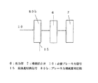
図1はこの発明の実施の形態1による鉄道車両用滑走制御装置の構成を示すブロック図である。図において、図5に示す従来のものと同一もしくは相当部分は同一符号で示し、説明は省略する。80は滑走量・ブレーキ力増減量判定部である。
【0011】
車輪滑走発生時、判断部5で滑走軸、非滑走軸を判断し、滑走軸の滑走量及び非滑走軸のブレーキ力増減量を滑走量・ブレーキ力増減量判定部80で算出し、出力部6を経由して滑走軸は滑走防止弁7を用いてブレーキ力を低減し、非滑走軸は、出力部6を経由して滑走防止弁7を用いてブレーキ力を増加する。
【0012】
滑走量・ブレーキ力増減量判定部80では、先頭車の滑走軸(後台車)の1滑走中の滑走回数に応じて非滑走軸(前台車)のブレーキ力増加量を算出し、例えば、1滑走中に
1回目滑走時には非滑走軸のブレーキ力増加量を10%
2回目滑走時には非滑走軸のブレーキ力増加量を15%
3回目滑走時には非滑走軸のブレーキ力増加量を20%
とすることで、非滑走軸のブレーキ力の増減を図る。
【0013】
なお、鉄道車両の走行方向を示す前後進切換信号(後述の実施の形態3のものと同様なもの)を速度入力部2、速度差検出部3、加減速度検出部4、判断部5、滑走量・ブレーキ増減量判定部80等の少なくともいずれか1つに入力することで、速度センサ1a〜1dからの信号がそれぞれ前台車(非滑走軸を含む)、後台車(滑走軸を含む)のいずれからのものかが事前に判断できる。
【0014】
実施の形態2.
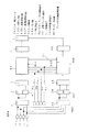
図2はこの発明の実施の形態2による鉄道車両用滑走制御装置の構成を示すブロック図である。滑走量・ブレーキ増減量判定部80aに必要ブレーキ力10、各車軸(4軸分)毎のブレーキ力増加信号9a、9b、9c、9dを入力した点が実施の形態1と異なる。なお、ブレーキ力増加信号9a、9b、9c、9dは、例えば各車軸毎の軸重(加重量)を測定する加重計からの信号とする。
【0015】
車輪滑走発生時は実施の形態1と同様な動作であり、ブレーキ作用時、各軸(4軸分)に関するブレーキ力増加信号9a〜9d、および必要ブレーキ力信号10を滑走量・ブレーキ力増減量判定部80aに入力することで、滑走量・ブレーキ力増減量判定部80aでは、軸重移動により軸重の増加する非滑走軸(前台車)のブレーキ力の増加量(増加したブレーキ力と必要ブレーキ力の関係)に応じて、軸重の軽減される滑走軸(後台車)のブレーキ力低減量(低減するブレーキ力と必要ブレーキ力の関係)を算出し、出力部6を経由して滑走防止弁7を用いてブレーキ力を低減することで、車両で必要なブレーキ力を確保する。
【0016】
実施の形態3.
図3はこの発明の実施の形態3による鉄道車両用滑走制御装置の構成を示す部分ブロック図である。ブレーキ力加減量判定部80bではブレーキ作用時、車両に必要なブレーキ力を示す必要ブレーキ力信号10と前後進切換信号15を入力する。ブレーキ力加減量判定部80bでは前後進切換信号15により1車両における前台車と後台車を判断することが可能となる。
【0017】
従って、ブレーキ作用中、予め前台車は軸重移動により滑走しにくい状態になるために、必要ブレーキ力信号10から荷重の10%増加させ、すなわち、
【0018】
(増加分)=(荷重)×0.1(10%)
【0019】
を加えたブレーキ力として算出し、その増加分だけ後台車で低減させることで、前・後台車の車輪滑走の発生を未然に防止する。
【0020】
実施の形態4.
また、従来の鉄道車両用滑走制御装置は1重系構成のため、故障した場合、新幹線車両用滑走制御装置の機能が不能となる。そこでこの実施の形態では、予備系鉄道車両用滑走制御装置を追加し、お互いを相互監視することで、万一故障した場合、自動的に切換えるようにした。
【0021】
図4はこの発明の実施の形態4による鉄道車両用滑走制御装置の構成を示すブロック図である。上記実施の形態1〜3による車両用滑走制御装置を通常系と位置付け、通常系と共用する速度センサ1a〜1d、ブレーキ力増加信号9a〜19d、滑走防止弁7、必要ブレーキ力信号10、前後進切換信号15、独立した速度入力部2X、速度差検出部3X、加減速度検出部4X、判断部5X、出力部6X、滑走量・ブレーキ力増減量判定部80X、および監視信号11で構成する予備系車両用滑走制御装置を追加する。
【0022】
通常系と予備系については滑走量・ブレーキ力増減量判定部80間で監視信号11にて互いを監視し、一定時間内に応答が無い場合もしくは通常系、予備系で認識する速度に速度差が発生した場合、予備系に自動的に切換える構成である。
【0023】
なお、上記各実施の形態は、適宜組み合わせが可能であり、実施の形態1〜3の装置はそれぞれ、実施の形態4のように通常系と予備系を組み合わせて構成してもよい。
【0024】
【発明の効果】
以上のようにこの発明によれば、走行する鉄道車両のブレーキ作用時に発生する車輪滑走を抑制する鉄道車両用滑走制御装置であって、各車軸の回転速度に基づき滑走を判定する滑走判断手段と、この滑走判断手段の判定に基づき、滑走軸の滑走回数に応じて、非滑走軸のブレーキ力を増加させるように各車軸のブレーキ力を制御する信号を発生する滑走量・ブレーキ力増減量判定手段と、を備えたことを特徴とする鉄道車両用滑走制御装置としたので、滑走状況に応じてロスしたブレーキ力量を補うようにブレーキ力を増加させることにより所望のブレーキ力を保ちながら滑走の抑制が行える。
【0025】
また、走行する鉄道車両のブレーキ作用時に発生する車輪滑走を抑制する鉄道車両用滑走制御装置であって、各車軸の回転速度に基づき滑走を判定する滑走判断手段と、各車軸でのブレーキ力増加を示す信号を入力すると共に前記滑走判断手段の判定に基づき、ブレーキ作用時に軸重の増加する非滑走軸のブレーキ力の増加量に応じて、軸重の軽減される滑走軸のブレーキ力を低減するように各車軸のブレーキ力を制御する信号を発生する滑走量・ブレーキ力増減量判定手段と、を備えたことを特徴とする鉄道車両用滑走制御装置としたので、ブレーキ作用時の軸重移動によるブレーク力の変化を考慮してブレーキ力の増減を行うことにより、より適切に所望のブレーキ力を保ちながら滑走の抑制が行える。
【0026】
また、走行する鉄道車両のブレーキ作用時に発生する車輪滑走を防止する鉄道車両用滑走制御装置において、車両の走行方向を示す前後切換信号を入力し、予め軸重移動により滑走しにくい状態になる前台車はブレーキ力を増加させ、その分、後台車はブレーキ力を減少させるように各車軸のブレーキ力を制御する信号を発生するブレーキ力増減量判定手段を備えたことを特徴とする鉄道車両用滑走制御装置としたので、予め車輪滑走を抑制することができる。
【図面の簡単な説明】
【図1】この発明の実施の形態1による鉄道車両用滑走制御装置の構成を示すブロック図である。
【図2】この発明の実施の形態2による鉄道車両用滑走制御装置の構成を示すブロック図である。
【図3】この発明の実施の形態3による鉄道車両用滑走制御装置の構成を示すブロック図である。
【図4】この発明の実施の形態4による鉄道車両用滑走制御装置の構成を示すブロック図である。
【図5】従来の鉄道車両用滑走制御装置のブロック図である。
【符号の説明】
1a〜1d 速度センサ、2 速度入力部、3 速度差検出部、4 加減速度検出部、5 判断部、6 出力部、7 滑走防止弁、80,80a 滑走量・ブレーキ力増減量判定部、80b ブレーキ力増減量判定部。[0001]
TECHNICAL FIELD OF THE INVENTION
BACKGROUND OF THE
[0002]
[Prior art]
FIG. 5 is a block diagram showing a configuration of a conventional railroad vehicle sliding control device. In FIG. 5, 1a to 1d are speed sensors, 2 is a speed input unit, 3 is a speed difference detecting unit, 4 is an acceleration / deceleration detecting unit, 5 is a judging unit for judging the occurrence of gliding, 8 is a gliding amount judging unit, and 6 is a gliding amount judging unit. The
[0003]
The
[0004]
Here, the
[0005]
[Problems to be solved by the invention]
Since the conventional sliding control device for railway vehicles is configured as described above, assuming that sliding occurs due to low adhesion between the wheels and the rails in rainy weather, the axle weight movement of the front and rear bogies is considered. Because the axle weight moves on the bogie in the direction of travel when braking, the non-sliding axis will be slid, and the non-sliding axis will also be slid when the wheels are slid. There was a problem of doing.
[0006]
The present invention has been made in order to solve the above-mentioned problems, and when a wheel slide occurs during a braking operation, the brake force is appropriately increased or decreased so as not to induce the sliding on the non-sliding axis, and the wheel slide is suppressed. It is an object of the present invention to provide a sliding control device for railway vehicles.
[0007]
[Means for Solving the Problems]
In view of the above-mentioned object, the present invention is a sliding control device for a railway vehicle that suppresses wheel sliding that occurs during a braking action of a running railway vehicle, and a sliding determining unit that determines the sliding based on the rotation speed of each axle. Based on the determination of the sliding determination means, determines a sliding amount / braking force increase / decrease amount that generates a signal for controlling the braking force of each axle so as to increase the braking force of the non-sliding axis according to the number of times of sliding of the sliding axis. Means, and a sliding control device for a railway vehicle.
[0008]
Also, there is provided a sliding control device for a railway vehicle for suppressing wheel sliding that occurs when a braking operation of a running railway vehicle is performed, a sliding determining means for determining the sliding based on the rotation speed of each axle, and a braking force increase for each axle. A signal indicating that the axle load is reduced and the axle load is reduced in accordance with the increase in the braking force of the non-sliding axis, the axle load of which increases when the brake is actuated. And a sliding amount / braking force increase / decrease determining means for generating a signal for controlling a braking force of each axle.
[0009]
Further, in a sliding control device for a railway vehicle for preventing a wheel from sliding when a running railway vehicle brakes, a forward / backward switching signal indicating a traveling direction of the vehicle is inputted, and before the sliding becomes difficult due to axle load movement. The railway vehicle is provided with a braking force increase / decrease determining means for generating a signal for controlling the braking force of each axle so that the bogie increases the braking force and the rear bogie accordingly reduces the braking force. It is in the sliding control device.
[0010]
BEST MODE FOR CARRYING OUT THE INVENTION
FIG. 1 is a block diagram showing a configuration of a railway vehicle sliding control device according to
[0011]
When a wheel slide occurs, the determining
[0012]
The sliding amount / braking force increase / decrease determining
15% increase in non-sliding axis braking force during second run
20% increase in braking force on non-sliding axis during 3rd run
By doing so, increase or decrease the braking force of the non-sliding shaft.
[0013]
Note that a forward / backward switching signal (similar to that of a third embodiment described later) indicating the traveling direction of the railway vehicle is input to the
[0014]
FIG. 2 is a block diagram showing a configuration of a railway vehicle sliding control device according to
[0015]
When a wheel slide occurs, the operation is the same as that of the first embodiment. When a brake is applied, the brake force increase signals 9a to 9d and the necessary
[0016]
FIG. 3 is a partial block diagram showing a configuration of a railway vehicle sliding control device according to
[0017]
Therefore, during the braking operation, the front bogie becomes in a state in which it is difficult to slide due to axle load movement, so that the required
[0018]
(Increase) = (load) x 0.1 (10%)
[0019]
Is calculated as the braking force to which the vehicle has been added, and the increased amount is reduced by the rear bogie, thereby preventing the front and rear bogies from sliding on wheels.
[0020]
Further, since the conventional sliding control device for railway vehicles has a single-layer configuration, if it fails, the function of the sliding control device for Shinkansen vehicles becomes impossible. Therefore, in this embodiment, a sliding control device for a standby railway vehicle is added, and mutual monitoring is performed to each other, so that if a failure occurs, the switching is automatically performed.
[0021]
FIG. 4 is a block diagram showing a configuration of a railway vehicle sliding control device according to
[0022]
The normal system and the standby system monitor each other with the monitoring signal 11 between the sliding amount / braking force increase / decrease
[0023]
The above embodiments can be appropriately combined with each other, and the devices of the first to third embodiments may be configured by combining the normal system and the standby system as in the fourth embodiment.
[0024]
【The invention's effect】
As described above, according to the present invention, there is provided a sliding control device for a railway vehicle that suppresses wheel sliding that occurs during a braking operation of a running railway vehicle, wherein the sliding determining unit determines the sliding based on the rotation speed of each axle. Based on the determination of the sliding determination means, determines a sliding amount / braking force increase / decrease amount that generates a signal for controlling the braking force of each axle so as to increase the braking force of the non-sliding axis according to the number of times of sliding of the sliding axis. Means, and a sliding control device for a railway vehicle characterized by comprising a braking force that is increased according to a sliding condition to compensate for a lost braking force amount, thereby maintaining a desired braking force while maintaining a desired braking force. Suppression can be performed.
[0025]
Also, there is provided a sliding control device for a railway vehicle for suppressing wheel sliding that occurs when a braking operation of a running railway vehicle is performed, a sliding determining means for determining the sliding based on the rotation speed of each axle, and a braking force increase for each axle. A signal indicating that the axle load is reduced and the axle load is reduced in accordance with the increase in the braking force of the non-sliding axis, the axle load of which increases when the brake is actuated. And a sliding amount / braking force increase / decrease determining means for generating a signal for controlling a braking force of each axle. By increasing or decreasing the braking force in consideration of the change in the braking force due to the movement, it is possible to more appropriately suppress the gliding while maintaining the desired braking force.
[0026]
Further, in a sliding control device for a railway vehicle for preventing a wheel from sliding when a running railway vehicle brakes, a forward / backward switching signal indicating a traveling direction of the vehicle is inputted, and before the sliding becomes difficult due to axle load movement. The railway vehicle is provided with a braking force increase / decrease determining means for generating a signal for controlling the braking force of each axle so that the bogie increases the braking force and the rear bogie accordingly reduces the braking force. Since the sliding control device is used, wheel sliding can be suppressed in advance.
[Brief description of the drawings]
FIG. 1 is a block diagram showing a configuration of a sliding control device for a railway vehicle according to a first embodiment of the present invention.
FIG. 2 is a block diagram showing a configuration of a railway vehicle sliding control device according to
FIG. 3 is a block diagram showing a configuration of a railway vehicle sliding control device according to
FIG. 4 is a block diagram showing a configuration of a railway vehicle sliding control device according to
FIG. 5 is a block diagram of a conventional sliding control device for a railway vehicle.
[Explanation of symbols]
1a to 1d speed sensor, 2 speed input section, 3 speed difference detection section, 4 acceleration / deceleration detection section, 5 judgment section, 6 output section, 7 anti-skid valve, 80, 80a judgment section for slip / brake force increase / decrease, 80b Brake force increase / decrease determination unit.
Claims (3)
各車軸の回転速度に基づき滑走を判定する滑走判断手段と、
この滑走判断手段の判定に基づき、滑走軸の滑走回数に応じて、非滑走軸のブレーキ力を増加させるように各車軸のブレーキ力を制御する信号を発生する滑走量・ブレーキ力増減量判定手段と、
を備えたことを特徴とする鉄道車両用滑走制御装置。A sliding control device for a railway vehicle, which suppresses wheel sliding generated during a braking action of a traveling railway vehicle,
A sliding determining means for determining a sliding based on a rotation speed of each axle;
A sliding amount / braking force increase / decrease determining means for generating a signal for controlling the braking force of each axle so as to increase the braking force of the non-sliding axis according to the number of times of sliding of the sliding axis based on the determination of the sliding determining means. When,
A sliding control device for a railway vehicle, comprising:
各車軸の回転速度に基づき滑走を判定する滑走判断手段と、
各車軸でのブレーキ力増加を示す信号を入力すると共に前記滑走判断手段の判定に基づき、ブレーキ作用時に軸重の増加する非滑走軸のブレーキ力の増加量に応じて、軸重の軽減される滑走軸のブレーキ力を低減するように各車軸のブレーキ力を制御する信号を発生する滑走量・ブレーキ力増減量判定手段と、
を備えたことを特徴とする鉄道車両用滑走制御装置。A sliding control device for a railway vehicle, which suppresses wheel sliding generated during a braking action of a traveling railway vehicle,
A sliding determining means for determining a sliding based on a rotation speed of each axle;
A signal indicating an increase in the braking force at each axle is input, and the axle load is reduced according to the increase in the braking force of the non-sliding axle, which increases the axle load during braking, based on the determination of the sliding determination means. A sliding amount / braking force increase / decrease determining means for generating a signal for controlling the braking force of each axle so as to reduce the braking force of the sliding shaft;
A sliding control device for a railway vehicle, comprising:
Priority Applications (1)
| Application Number | Priority Date | Filing Date | Title |
|---|---|---|---|
| JP2003105596A JP4184137B2 (en) | 2003-04-09 | 2003-04-09 | Rail vehicle rolling control device |
Applications Claiming Priority (1)
| Application Number | Priority Date | Filing Date | Title |
|---|---|---|---|
| JP2003105596A JP4184137B2 (en) | 2003-04-09 | 2003-04-09 | Rail vehicle rolling control device |
Publications (2)
| Publication Number | Publication Date |
|---|---|
| JP2004306865A true JP2004306865A (en) | 2004-11-04 |
| JP4184137B2 JP4184137B2 (en) | 2008-11-19 |
Family
ID=33468062
Family Applications (1)
| Application Number | Title | Priority Date | Filing Date |
|---|---|---|---|
| JP2003105596A Expired - Fee Related JP4184137B2 (en) | 2003-04-09 | 2003-04-09 | Rail vehicle rolling control device |
Country Status (1)
| Country | Link |
|---|---|
| JP (1) | JP4184137B2 (en) |
Cited By (6)
| Publication number | Priority date | Publication date | Assignee | Title |
|---|---|---|---|---|
| JP2007210358A (en) * | 2006-02-07 | 2007-08-23 | Odakyu Dentetsu Kk | Brake control system for railway vehicles |
| WO2009154048A1 (en) * | 2008-06-20 | 2009-12-23 | 三菱電機株式会社 | Train slide control device and train slide control method |
| JP4794690B2 (en) * | 2008-06-20 | 2011-10-19 | 三菱電機株式会社 | Train sliding control device and train sliding control method |
| WO2015056081A1 (en) * | 2013-10-18 | 2015-04-23 | Toyota Jidosha Kabushiki Kaisha | Control apparatus and control method of vehicle |
| CN114426034A (en) * | 2022-01-14 | 2022-05-03 | 中车青岛四方机车车辆股份有限公司 | Rail vehicle sliding state detection method and rail vehicle |
| CN114834414A (en) * | 2021-02-02 | 2022-08-02 | 纳博特斯克有限公司 | Brake control device for railway vehicle and brake device for railway vehicle |
Families Citing this family (1)
| Publication number | Priority date | Publication date | Assignee | Title |
|---|---|---|---|---|
| CN103183037B (en) * | 2011-12-29 | 2016-03-02 | 中国北车股份有限公司 | electric locomotive adhesion control method and device |
-
2003
- 2003-04-09 JP JP2003105596A patent/JP4184137B2/en not_active Expired - Fee Related
Cited By (13)
| Publication number | Priority date | Publication date | Assignee | Title |
|---|---|---|---|---|
| JP2007210358A (en) * | 2006-02-07 | 2007-08-23 | Odakyu Dentetsu Kk | Brake control system for railway vehicles |
| CN102036866B (en) * | 2008-06-20 | 2014-10-01 | 三菱电机株式会社 | train slide control device and train slide control method |
| WO2009153883A1 (en) * | 2008-06-20 | 2009-12-23 | 三菱電機株式会社 | Train slide controller and train slide control method |
| CN102036866A (en) * | 2008-06-20 | 2011-04-27 | 三菱电机株式会社 | Train slide control device and train slide control method |
| JP4794690B2 (en) * | 2008-06-20 | 2011-10-19 | 三菱電機株式会社 | Train sliding control device and train sliding control method |
| US8457818B2 (en) | 2008-06-20 | 2013-06-04 | Mitsubishi Electric Corporation | Train slide control device and train slide control method |
| WO2009154048A1 (en) * | 2008-06-20 | 2009-12-23 | 三菱電機株式会社 | Train slide control device and train slide control method |
| WO2015056081A1 (en) * | 2013-10-18 | 2015-04-23 | Toyota Jidosha Kabushiki Kaisha | Control apparatus and control method of vehicle |
| CN105636822A (en) * | 2013-10-18 | 2016-06-01 | 丰田自动车株式会社 | Vehicle control device and control method |
| CN105636822B (en) * | 2013-10-18 | 2018-01-23 | 丰田自动车株式会社 | Vehicle control apparatus and control method |
| US9884568B2 (en) | 2013-10-18 | 2018-02-06 | Toyota Jidosha Kabushiki Kaisha | Control apparatus and control method of vehicle |
| CN114834414A (en) * | 2021-02-02 | 2022-08-02 | 纳博特斯克有限公司 | Brake control device for railway vehicle and brake device for railway vehicle |
| CN114426034A (en) * | 2022-01-14 | 2022-05-03 | 中车青岛四方机车车辆股份有限公司 | Rail vehicle sliding state detection method and rail vehicle |
Also Published As
| Publication number | Publication date |
|---|---|
| JP4184137B2 (en) | 2008-11-19 |
Similar Documents
| Publication | Publication Date | Title |
|---|---|---|
| JP4739194B2 (en) | Brake system for railway vehicles | |
| JP4246919B2 (en) | Rail vehicle derailment detection method and derailment detection device | |
| JP2865651B2 (en) | Brake warranty module | |
| JP7606356B2 (en) | Brake control device for railroad vehicles, Brake device for railroad vehicles | |
| JP2000006807A (en) | Railway vehicle and abnormality detection method during traveling | |
| KR101465525B1 (en) | Linking system for anti-skid control of railway vehicle and method | |
| US10668906B2 (en) | Brake control device | |
| JP2004306865A (en) | Sliding control device for railway vehicles | |
| JPH0558267A (en) | Method for detecting speed of vehicle provided with slip controllable wheel | |
| US6840587B2 (en) | Vehicle brake system having an electronic unit for determining a vehicle reference speed | |
| JP2002079928A (en) | Method and apparatus for detecting lane change | |
| JP4921680B2 (en) | Brake system for vehicles equipped with ABS device or anti-skid device | |
| JP4372740B2 (en) | Brake control device and brake control method | |
| JP4278795B2 (en) | Wheel sliding prevention method and apparatus | |
| JP2004175156A (en) | Abnormal vibration detection device for railway rolling stock | |
| JPH10217929A (en) | Gliding controller | |
| JP2003237561A (en) | Brake device for railway rolling stock and control method thereof | |
| EP1697194A1 (en) | Lateral acceleration control system | |
| JP3205759B2 (en) | Brake control device for railway vehicles | |
| JP2017071247A (en) | Derailment state detection device and derailment state detection method | |
| JP2773581B2 (en) | Sliding control device for vehicles | |
| JP2777991B2 (en) | Vehicle braking control device | |
| JP2664612B2 (en) | Brake control system | |
| JPH0217384B2 (en) | ||
| CN115782964A (en) | Diagnosis method, system and train for axle locking fault of train |
Legal Events
| Date | Code | Title | Description |
|---|---|---|---|
| A131 | Notification of reasons for refusal |
Free format text: JAPANESE INTERMEDIATE CODE: A131 Effective date: 20070313 |
|
| A977 | Report on retrieval |
Free format text: JAPANESE INTERMEDIATE CODE: A971007 Effective date: 20070320 |
|
| A521 | Request for written amendment filed |
Free format text: JAPANESE INTERMEDIATE CODE: A523 Effective date: 20070511 |
|
| A131 | Notification of reasons for refusal |
Free format text: JAPANESE INTERMEDIATE CODE: A131 Effective date: 20070703 |
|
| A521 | Request for written amendment filed |
Free format text: JAPANESE INTERMEDIATE CODE: A523 Effective date: 20070831 |
|
| A131 | Notification of reasons for refusal |
Free format text: JAPANESE INTERMEDIATE CODE: A131 Effective date: 20080129 |
|
| A521 | Request for written amendment filed |
Free format text: JAPANESE INTERMEDIATE CODE: A523 Effective date: 20080327 |
|
| TRDD | Decision of grant or rejection written | ||
| A01 | Written decision to grant a patent or to grant a registration (utility model) |
Free format text: JAPANESE INTERMEDIATE CODE: A01 Effective date: 20080902 |
|
| A01 | Written decision to grant a patent or to grant a registration (utility model) |
Free format text: JAPANESE INTERMEDIATE CODE: A01 |
|
| A61 | First payment of annual fees (during grant procedure) |
Free format text: JAPANESE INTERMEDIATE CODE: A61 Effective date: 20080903 |
|
| FPAY | Renewal fee payment (event date is renewal date of database) |
Free format text: PAYMENT UNTIL: 20110912 Year of fee payment: 3 |
|
| R150 | Certificate of patent or registration of utility model |
Ref document number: 4184137 Country of ref document: JP Free format text: JAPANESE INTERMEDIATE CODE: R150 Free format text: JAPANESE INTERMEDIATE CODE: R150 |
|
| FPAY | Renewal fee payment (event date is renewal date of database) |
Free format text: PAYMENT UNTIL: 20110912 Year of fee payment: 3 |
|
| FPAY | Renewal fee payment (event date is renewal date of database) |
Free format text: PAYMENT UNTIL: 20120912 Year of fee payment: 4 |
|
| FPAY | Renewal fee payment (event date is renewal date of database) |
Free format text: PAYMENT UNTIL: 20130912 Year of fee payment: 5 |
|
| R250 | Receipt of annual fees |
Free format text: JAPANESE INTERMEDIATE CODE: R250 |
|
| R250 | Receipt of annual fees |
Free format text: JAPANESE INTERMEDIATE CODE: R250 |
|
| R250 | Receipt of annual fees |
Free format text: JAPANESE INTERMEDIATE CODE: R250 |
|
| R250 | Receipt of annual fees |
Free format text: JAPANESE INTERMEDIATE CODE: R250 |
|
| R250 | Receipt of annual fees |
Free format text: JAPANESE INTERMEDIATE CODE: R250 |
|
| R250 | Receipt of annual fees |
Free format text: JAPANESE INTERMEDIATE CODE: R250 |
|
| LAPS | Cancellation because of no payment of annual fees |