【0001】
【発明の属する技術分野】
本発明は、汎用コンバインのロ−クロップ装置に関し、農業機械の技術分野に属する。
【0002】
【従来の技術】
従来から汎用コンバインは、稲、麦に限らず大豆、そば等の穀類の刈取、脱穀作業ができるように構成されており、脱穀装置は全稈投入式を搭載している。そして、刈取前処理装置は、稲、麦の収穫作業では、前部の上方位置に掻込みリ−ルが軸架され、その下方位置に刈取装置が設けられ、その後方位置に、前記刈取装置の刈幅と略同等の幅を有する掻込みオ−ガが横軸に支持して設けられ、該掻込みオ−ガの一側後部に搬送コンベヤからなるエレベ−タが装備されていた。
【0003】
又、大豆、そば等の丈の低い茎稈を収穫する汎用コンバインにあっては、刈取前処理装置は、掻込みリ−ルを外して、刈取装置の前方低位置から上方にかけて左右一対のラグベルトからなるロ−クロップ装置を設けて比較的丈の低い茎稈を両側から係止して、挟持状態にしながら搬送して刈取、収穫する構成になっている。そして、従来型のこの種のコンバインは、ロ−クロップ装置を上下昇降自由に吊り下げる鎖状体を刈取昇降フレ−ムに連結支持し、その刈取昇降フレ−ムを昇降用油圧シリンダに連結支持して上下昇降できる構成を採用している。(例えば、特許文献1参照)。
【0004】
【特許文献1】
特開2001−275450号公報(第1、乃至5頁、第2図、及び4図)
【0005】
【発明が解決しようとする課題】
上述した従来型において、そばや豆類を収穫する汎用コンバインのロ−クロップ装置は、前方低位置から刈取装置の上方を経て後方まで延長した左右一対の掻込みラグベルトを設けて構成している。そして、圃場の茎稈は、分草作用を受けた後、左右一対のラグベルトで挟まれながら後方に搬送される過程で株元が刈取装置で刈り取られ、後方のテ−ブル上に達して掻込みオ−ガに供給される。このように、茎稈の収穫をするロ−クロップ装置は、従来型の図2(前記公開特許公報参照)に示すように、昇降用油圧シリンダ14を伸縮させて刈取昇降フレ−ム11と鎖状体13とを介して上下調節ができる構成にはなっているが、分草杆やラグベルトを横方向に移動調節して植付けた畝幅、又は植付け条列の間隔に合わせて分草幅を調節することができず、刈取茎稈条列に対して分草杆と掻込みラグベルトを真正面に合わせることが難しい課題があった。
【0006】
【課題を解決するための手段】
本発明は、上述した課題を解決するために、次の如き技術手段を講ずるものである。まず、請求項1の発明は、掻込みオ−ガ1の前方において、左右一対の掻込みラグベルト2、2を、搬送始端部を前方下部にし、搬送終端部を後方上部にして側面視傾斜状に軸架して設け、該掻込みラグベルト2、2は、前部低位置で分草後の茎稈を左右両側の搬送ラグ3で受継いで保持しながら搬送し、途中で株元が刈取られた茎稈をそのまま後方のテ−ブル4上に搬送して供給する構成としたロ−クロップ装置5を有する汎用コンバインにおいて、該ロ−クロップ装置5は、左右一対の掻込みラグベルト2、2を伝動する駆動プ−リ6、6の中心部を回動支点Pとして左右方向に回動自由に構成し、前記ロ−クロップ装置5は、前部左右の分草杆7、7と、左右一対の掻込みラグベルト2、2とを、別々に支持した左右の支持枠8、8を、茎稈搬送通路9の下側に配置した横向きの連結フレ−ム10によって枢着連結して左右一体に構成し、該ロ−クロップ装置5は、前記左右一対の掻込みラグベルト2、2の後部に設けた前記回動支点Pを中心にして前部を左右に回動調節自由に構成した汎用コンバインのロ−クロップ装置であって、左右の分草杆と左右一対の掻込みラグベルトとを左右別々に取付けて支持した左右の支持枠を連結フレ−ムで連結して、これらを一体の平行リンク機構に構成している。このように一体とした前部の左右分草杆と後続する左右の掻込みラグベルトは、刈取り対象とする茎稈植付け条列に合わせて、後部を回動支点にして前部を左右横方向に調節して正しく条合わせして刈取り、搬送ができる構成としている。
【0007】
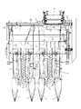
つぎに、請求項2の発明は、前部左右の分草杆7、7と、それに後続する左右一対の掻込みラグベルト2、2とは、それぞれ左右の支持枠8、8に取付支持して設け、該支持枠8、8は、前記掻込みラグベルト2、2の間に形成した茎稈搬送通路9の下側に配置した横向きの連結フレ−ム10によって左右一体に枢着連結して一条のロ−クロップ装置5を構成し、該ロ−クロップ装置5は、掻込みオ−ガ1の前方に複数条を並列状態に配置して設け、これら各ロ−クロップ装置5は、後部の駆動プ−リ6、6の中心部を回動支点Pとして、前部をそれぞれ左右に回動調節自由に構成した請求項1記載の汎用コンバインのロ−クロップ装置であって、上記請求項1に係る1条のロ−クロップ装置を掻込みオ−ガの前方に複数条並列状態に並べて構成したものである。このように、本案に係るロ−クロップ装置は、広幅刈りのコンバインの場合、多条刈りができるよう複数条を横並びに並列に配置して、それぞれを刈取条ごとに左右に回動調節ができる構成にしたものである。
【0008】
つぎに、請求項3の発明は、左右の分草杆7、7と左右の掻込みラグベルト2、2とをそれぞれ支持した左右の支持枠8、8は、テ−ブル4の前方において、茎稈搬送通路9の下方を横切って設けた連結フレ−ム10によって枢着連結して一体に構成し、該連結フレ−ム10と前記テ−ブル4との間に搬送茎稈の株元を案内する株元案内板11を架け渡して構成した請求項1、又は2記載の汎用コンバインのロ−クロップ装置であって、茎稈搬送通路の下側を横切って設けている連結フレ−ムに茎稈が絡み付かず、テ−ブルまでの間、搬送茎稈の株元が確実に案内されて地面への落下を防止し、ロスを発生を未然に防止できるものとなっている。
【0009】
【発明の効果】
本発明は、以上のような構成、作用を有するものであって、まず、請求項1の発明は、左右の分草杆とそれに後続する左右一対の掻込みラグベルトからなるロ−クロップ装置を、圃場に植付けられている大豆等の茎稈条列に対して正対した位置になるように、横に移動調節して収穫作業ができる効果を有する。特に、本案の場合、ロ−クロップ装置は、茎稈の搬送通路を挟んで左右別々に設けた分草杆と掻込みラグベルトを連結フレ−ムによって一体に枢着状態に連結して構成したから、刈取条列ごとに横に移動調節が自由にできる特徴がある。
【0010】
そして、請求項2の発明は、刈幅の広い多条刈りコンバインにおいて、有効であって、ロ−クロップ装置の横移動調節で全体の刈幅を広げることもできる効果がある。そして、ロ−クロップ装置は、並列状に横並びに配置したものを各刈取条ごとに左右調節して圃場の植え付け畝に合わせることもできる特徴がある。
【0011】
そして、請求項3の発明は、連結フレ−ムとその後方のテ−ブルとの間に株元案内板を架け渡して設けたから、連結フレ−ムに搬送茎稈が巻き付くのを防止できるものでありながら、その部分における地上への落下をなくしてロスを未然に防止して搬送茎稈を確実にテ−ブル上に搬送、供給できる特徴がある。
【0012】
【発明の実施の形態】
以下、本発明の実施の形態を図面に基づいて具体的に説明する。
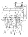
まず、刈取前処理装置12は、図1、及び図2に示すように、前部の接地位置に設けた左右の分草杆7、7と、それに後続した部位に左右一対の掻込みラグベルト2、2と、低位置の刈取装置13と、前部に軸架したゲ−ジホイル14(図2参照)とを一体構成としたロ−クロップ装置5と、その後部にテ−ブル4と、掻込みオ−ガ1と、一側のエレベ−タ15とを装備して構成している。
【0013】
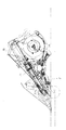
そこで、まず、ロ−クロップ装置5を構成する左右一対の掻込みラグベルト2、2は、図1に示すように、ベルトに所定間隔ごとに搬送ラグ3を装着し、左右から各搬送ラグ3を互いに内側に向けて対向させて配置し、茎稈を左右両側から挟持状態に係止して搬送可能に巻回しているが、その配置において、図面から解るように、各搬送ラグ3に搬送方向(後方)に対して後退角を持たせて構成している。そして、左右一対の掻込みラグベルト2、2は、図2に示すように、搬送終端部側を、下部をテ−ブル4に固着した支持筒16の上部に軸架している上下2段の駆動プ−リ6、6に巻回し、搬送始端部側を、上下2段の支持枠8、8の先端部に軸架した遊動プ−リ17、17に巻回して構成している。そして、左右一対の掻込みラグベルト2、2は、図2に示すように、搬送始端部側では搬送ラグ3が地表近くまで届く程度に低くし、搬送終端部側を高くして側面視傾斜状に構成している。そして、実施例の場合、左右一対の掻込みラグベルト2、2は、図面から解るように、左右のものを上下に若干の段差を設けて架設しており、両外側から内側に向けて突出している搬送ラグ3が相互に上下に交差(平面視で重合して同じ搬送通路を通過できる。)した構成としている。この構成によって、左右の搬送ラグ5は、回動中に干渉したり、衝突するのを回避できる特徴がある。
【0014】
そして、上記左右一対の掻込みラグベルト2、2は、図面から解るように、全体がベルトカバ−18で覆われ、図1、及び図2に示す実施例の場合は、前部にある左右の分草杆7、7を、上記左右一対の掻込みラグベルト2、2の遊動プ−リ17、17を軸架した左右の支持枠8、8に連結した構成としている。この場合、左右の両支持枠8、8は、図1に示すように、左側には左の分草杆7と左の掻込みラグベルト2(遊動プ−リ17を軸受している。)を取付けて支持し、右側には同様に、右の分草杆7と右の掻込みラグベルト2(遊動プ−リ17を軸受している。)とを支持した構成としている。そして、上記左右の支持枠8、8は、左右一対の掻込みラグベルト2、2の間に形成される茎稈搬送通路9の下側を横切って配置した連結フレ−ム10によって枢着状態に連結して一体に構成している。
【0015】
そして、上記の如く一体構成とした左右一対の掻込みラグベルト2、2は、搬送後部にある前記支持筒16の上部に軸架した駆動プ−リ6、6の中心部を回動支点Pにして搬送始端部側が左右方向へ回動調節できる構成としている。この場合、上記支持筒16は、具体的な図面は省略しているが、回転する支持筒16の下部側に円弧形状の長孔を形成し、固定側(テ−ブル4側)に設けている係止ねじで係脱自由に固定する構成としている。したがって、掻込みラグベルト2、2は、支持筒16の下部に形成した円弧形状長孔の範囲内において回転調節ができ、係止ねじで固定することが可能になっている。この場合、前記左右の両支持枠8、8は、連結フレ−ム10によって枢着状態に連結され、平行リンク状に組まれた構成となっている。
【0016】
そして、株元案内板11は、図3、及び図4に示すように、前側の連結フレ−ム10と後方のテ−ブル4との間にできる空間を塞ぐように配置して、前部を連結フレ−ム10に取り付け、後部をテ−ブル4側にまで延長して固定している。この場合、茎稈株元の搬送ラインHは、図4に仮想線で示すように、株元案内板11の上方を通過する関係になっている。
【0017】
つぎに、円盤刈刃13は、前述した刈取装置13を指すものであり、実施例の場合、図2から解るように、油圧モ−タ19からチエン20を介して駆動スプロケット21に伝動する構成としている。そして、円盤刈刃13は、図1に示すように、各刈取条列ごとに縦軸に軸着して配置しており、左右一対の掻込みラグベルト2、2の搬送ラグ3によって保持されて搬送中の茎稈株元を刈取るように構成している。そして、円盤刈刃13は、前記した左側の支持枠8に支持され、ロ−クロップ装置5と一体となって関係位置を狂わせない状態で横方向に調節移動する構成となっている。
【0018】
つぎに、ゲ−ジホイル14は、図2、及び図3に仮想線で示すように、これの上下調節によってロ−クロップ装置5の地上高さが決まる主要な役目を果たす構成としている。
そして、掻込みオ−ガ1は、図1、及び図2に示すように、テ−ブル4の後部上方に横向きに軸装しており、その図に示すように、外周には搬送螺旋25を巻き付けて設け、前側から茎稈を掻き込みながら側方へ搬送し、エレベ−タ15側に達すると、掻込みクランクフィンガ−26により後側のエレベ−タ15に供給する構成としている。
【0019】
そして、エレベ−タ15は、始端部を上述のとおり、掻込みオ−ガ1に臨ませて設け、終端部を後部上方の脱穀装置に連結して扱室の供給部に接続して設け、茎稈の全部を投入する構成にしている。
つぎに、図5、及び図6に示す実施例の分草ワイヤ−27、27について説明する。
【0020】
該分草ワイヤ−27、27は、図面から解るように、左右一対からなり、始端部をロ−クロップ装置5の搬送始端部分の外側に固定し、左右の掻込みラグベルト2、2の非搬送側(ラグベルトが前方に向かって移動する側)の上方を経て終端部を、後部のリフトア−ム28に連結して張り渡した構成としている。このように、両側の分草ワイヤ−27、27は、図5、及び図6に示す実施例のように、側面視においては、前が低く、後ろを高くした傾斜状になり、平面視ではロ−クロップ装置5の左右外側に沿わせて前後方向にほぼ平行状に配置した構成としている。
【0021】
上述のように構成した分草ワイヤ−27、27は、ロ−クロップ装置5で茎稈を後方に搬送するとき、外側に倒伏して移動している搬送茎稈の上部を載せた状態で後方に案内し、更にワイヤ−の外側の茎稈と絡むのを未然に防止して整然と分草、案内する特徴がある。なお、上記分草ワイヤ−27は、分草ロットに代えて構成しても同様の作用、効果を期待することができる。
【0022】
このように構成した本案の実施例は、請求項1の発明の場合、左右の分草杆7、7とそれに後続する左右一対の掻込みラグベルト2、2からなるロ−クロップ装置5を、圃場に植付けられている大豆等の茎稈条列に合わせて、後部の駆動プ−リ6、6の中心部分を回動支点Pとして横に移動調節してセットすることができる。この場合、ロ−クロップ装置5は、茎稈の搬送通路9を挟んで左右別々に設けた分草杆7、7と掻込みラグベルト2、2を左右の支持枠8、8と連結フレ−ム10によって平行リンク機構の如く、一体に連結して構成したから、刈取条列ごとに一体として横方向に移動調節することができるものとなっている。
【0023】
そして、請求項2の発明の場合は、刈幅の広い多条刈りコンバインにおいて、有効であって、ロ−クロップ装置5の横移動調節で全体の刈幅を広げることもできる効果がある。そして、ロ−クロップ装置5は、並列状に横並びに配置したものを各刈取条ごとに左右調節して圃場の植え付け畝に合わせることも可能になっている。
【0024】
そして、請求項3の発明は、連結フレ−ム10とその後方のテ−ブル4との間に株元案内板11を架け渡して設けたから、連結フレ−ム10に搬送茎稈が巻き付くのを防止できるものでありながら、その部分における茎稈の地上への落下をなくし、ロスを未然に防止して搬送茎稈を確実にテ−ブル4まで搬送することができるものとなった。
【0025】
別実施例1
つぎに、図7、図8、及び図9に基づいて別実施例1を説明する。
別実施例1は、汎用コンバインの脱穀装置に使用されているスクリュ−式扱胴の改良に関する発明である。従来の扱胴は、スクリュ−の高さが、外側(スクリュ−の外周)に装着しているツ−スの高さより高く構成されており、そのために、脱穀物が高いスクリュ−のために塊状で扱胴表面(スクリュ−の元側)で持ち回られ、そのまま選別室を経由して機外に排塵されることが多く、三番ロスが多く発生する課題があった。
【0026】
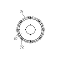
それに対して、別実施例1は、図7、及び図8に示すように、スクリュ−式扱胴30の外周に螺旋状に装着するスクリュ−31と、そのスクリュ−31の外周に取り付けるツ−ス32との高さをほぼ同等に構成したものである。
上述した従来構成の扱胴(ツ−スの高さよりスクリュ−の高さが高い扱胴)は、供給された脱穀物が高いスクリュ−に守られた状態でツ−スと外側の扱ぎ網による脱穀作用を受けずに、塊のまま排出されるものが多く、脱穀作用が不充分になっていた。
【0027】
別実施例1は、上述のように、スクリュ−31とツ−ス32との高さを同じにしたから、言い換えると、スクリュ−31を低くしたから、扱室に供給された脱穀物が外側の扱ぎ網とツ−ス32とによる扱ぎ作用を受け安く、確実に脱穀されることになった。このように、別実施例1の場合、スクリュ−31の高さが低くなった分、スクリュ−31によって持ち回られる脱穀物の層が薄くなってツ−ス32と外側の扱ぎ網との扱ぎ作用を受ける率が高くなり、脱穀処理が確実になった特徴がある。
【0028】
そして、スクリュ−式扱胴30は、図9に示すように、終端部分30aの扱胴径を小径にして、排塵、排稈がスム−スにできる構成としている。
別実施例2
つぎに、図10、及び図11に基づいて別実施例2を説明する。
【0029】
別実施例2は、グレンタンクに貯留している穀粒を機外に排出するために、エア−式穀粒搬送装置を利用した場合、グレンタンクの下部に装備した穀粒繰出装置の繰り出しロ−ルを軸方向に引き抜いて比較的簡単に取り出しのできる構成に関するものである。
【0030】
まず、穀粒繰出装置40は、図10に示すように、グレンタンク41の下側において、漏斗状に形成した傾斜案内板42の下側に、横向き円筒状に形成したケ−スの内部に羽根車から形成した繰り出しロ−ル43を左右方向の回転軸44によって軸架した構成としている。この場合、傾斜案内板42は、グレンタンク41の左右方向(図10の紙面の左右方向の意味、以下同じ)において、右側に片寄せた位置に設けられ、その下部に上記穀粒繰出装置40を連結して設けた構成とし、穀粒繰出装置40の左側に取出空間45を形成した構成となっている。
【0031】
そして、上記取出空間45は、前記回転軸44の全長H1より左右方向の空間の長さ(広さ)Hを長く(H1<H)しており、繰り出しロ−ル43を回転軸44と一体で穀粒繰出装置40から左側の取出空間45に引き出すことができる余裕を持たせた広さに構成している。そして、繰り出しロ−ル43は、図11に示すように、回転軸44の両端をフランジ46、46に着脱自由に軸受した構成としており、両端のナット47、47を外して右のフランジ46を外せば、回転軸44と一体で、取出空間45側に取り出しができる構成としている。
【0032】
そして、繰り出しロ−ル43は、図面に示すように、回転軸44の端部(外側)に伝動ギヤ48を軸着して原動側から回転動力が伝達されて回転し、上側の傾斜案内板42から供給される穀粒を下側の搬送風路49に定量づつ繰り出して落下する構成としている。そして、搬送風路49は、図10に示すように、基部側にブロワ−50の吹出口が連通され、搬送下手側には、グレンタンク41の上方に延長した穀粒搬送筒51に連通して穀粒を機外に排出する構成としている。
【0033】
なお、穀粒繰出装置40は、実施例を示す図10では右側にオフセットして左側に取出空間45を形成したが、相互に逆側に形成することは自由である。
以上のように、別実施例2は、穀粒を搬送風路49内に定量づつ繰り出す繰り出しロ−ル43を取り出す取出空間45を側部に形成したから、ロ−ル43の取り出しが容易となり、清掃等のメンテナンスが容易にできる特徴がある。
【0034】
別実施例3
つぎに、図12、乃至図14に基づいて別実施例3を説明する。
別実施例3は、コンバインのグレンタンクに関し、コンバイン車体に装備されている車体水平制御機構のピッチング制御装置を利用してグレンタンクに供給されている穀粒の表面を極力平らにして穀粒の充填率を高めてタンク容量を有効に利用しようとするものである。
【0035】
従来からコンバインは、図12に示すように、刈取脱穀作業中に刈取って脱穀選別した穀粒を、一番揚穀装置Aを経由してグレンタンクTに充填する場合、穀粒は、一番揚穀装置Aの穀粒排出口Bの近傍では高く貯留されるが、排出口Bから遠ざかるにつれて穀粒表面Kが低くなり、充填率が減少する傾向がある。
【0036】
そこで、別実施例3は、上記課題を解決して限られた容積のグレンタンクに、できるだけ多量の穀粒を貯留して充填率を高めようとするものである。
まず、グレンタンク55は、図13、及び図14に示すように、コンバインの車体56上に搭載し、脱穀装置の一番揚穀装置57に連通した穀粒排出口58から排出された穀粒を貯留する構成としている。そして、車体56は、図面には省略したが、クロ−ラ59が駆動スプロケット60の車軸61を支点にして後部が上下調節制御されるピッチング制御装置を装備した構成となっている。
【0037】
そして、グレンタンク55は、図面から解るように、その内部の前記穀粒排出口58に近い位置に満杯センサ62を設け、その下側でタンク中央に寄った位置に予備センサ63を設けた構成としている。そして、上述のピッチング制御装置は、予備センサ63が穀粒を検出すると、制御を開始し、前記満杯センサ62が穀粒を検出するまでピッチング制御の状態にある構成としている。
【0038】
具体的には、図13に示す実施例の場合、グレンタンク55は、穀粒排出口58が後ろ側に寄った位置にあるから、タンクが水平状態のとき供給された穀粒はその表面が後側が高く、前側が低く貯留される。すると、車体56は、図13に示すように、予備センサ63が穀粒を検出するとピッチング制御が作動してクロ−ラ59の後部を下げる方向に制御し、順次車体56を前傾姿勢に変化させてタンク55を前傾にして穀粒を、表面の低い前側に寄せて流動させ、穀粒表面を平らにすることができる。
【0039】
つぎに、図14に示す実施例の場合、グレンタンク55は、穀粒排出口58が前側寄りにあるから穀粒表面を平らにするために、車体59を後傾に制御して穀粒を後ろ側に流動して表面を平らにしながら作業を続けるものである。
このように、別実施例3は、コンバイン車体56に装備されているピッチング制御装置を利用して、車体56と一体のグレンタンク55を前傾、又は後傾に修正しながら穀粒を低い側に流動して貯留穀粒の表面を平らにし、充填率を上げることができる。
【0040】
別実施例4
つぎに、図15、及び図16に基づいて別実施例4を説明する。
従来のコンバインは、車体上に搭載した脱穀装置と、これに付随する1番、及び2番揚穀装置と、キャビンとがそれぞれ車体に装置された状態で相互間の連結がされておらず、強度上弱いばかりでなく、走行中に振動や騒音が発生する課題があった。
【0041】
別実施例4は、上記した各装置を連結フレ−ムによって一体的に連結して従来型の課題を解消せんとするものである。
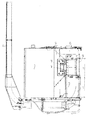
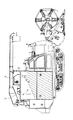
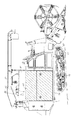
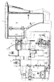
まず、前後フレ−ム65は、図15、及び図16に示すように、後部を脱穀装置66の後部に連結して前方に延長し、前部を脱穀装置66の前部に連結し、中間部分を2番揚穀装置67と1番揚穀装置68に連結して構成している。そして、前側縦フレ−ム69は、上部を1番揚穀装置68の穀粒排出口70とキャビン71に連結したキャビン連結フレ−ム72とに連結し、下部を前記前後フレ−ム65の前部に連結して構成している。そして、後側縦フレ−ム73は、下部を車体74に連結して2番揚穀装置67に沿わせてほぼ垂直に上に延長し、その2番揚穀装置67と、前後フレ−ム65とに連結して構成している。そして、後側縦フレ−ム73は、上部に2番揚穀装置67の上部にある補強フレ−ム75に連結して構成している。
【0042】
以上のように、別実施例4は、車体74上に搭載している脱穀装置66と、これに付随する1番、及び2番揚穀装置67、68と、キャビン71とを、前後フレ−ム65と前側縦フレ−ム69とキャビン連結フレ−ム72とによって、一体に連結して構成したから、機体強度を高めて丈夫になり、振動が少なくなり、騒音の発生を少なくした特徴がある。
【0043】
別実施例5
つぎに、図17、及び図18に基づいて別実施例5を説明する。
別実施例5は、大豆やそば等を収穫する汎用コンバインの1番揚穀装置に関し、揚穀装置の上部からグレンタンクに大豆等を供給する供給樋の改良発明である。
【0044】
従来の供給樋は、穀粒が円滑に流動するために最も急勾配を必要とするそばを基準として固定した構成としていたため、グレンタンクの穀粒充填率が低くなる課題があった。
まず、供給樋80は、1番揚穀装置81のバケットから搬送されてきた大豆やそばを樋内を流しながらグレンタンク82に供給する構成としている。この場合、供給樋80は、図18に示すように、機体側板83の中間部分に形成した円弧形状の長孔84に、供給樋80の外側に突出させて設けた係止具85を挿入して、上部を支点に下部を上下方向に調節する構成としている。そして、供給樋80は、図18の作用図に示すように、大豆の収穫作業時には上側に係止(勾配を緩くして)して収穫作業を行ない、そばの収穫作業時には下側に係止(勾配を急にして)して作業を行なうものである。
【0045】
一般に、グレンタンク82は、供給樋80の下端部が高い位置にあるほど多量の収穫穀物を充填できることが知られているが、そばのように、外形が偏平に近い形状の作物は転び難く供給樋80上を円滑に流動するためには急勾配に構成する必要がある。それに対して、大豆は、粒形が球形であるから転がり易く、供給樋80の勾配を緩くすることが可能で、充填率を高めることができる。
【0046】
このように、別実施例5は、1番揚穀装置81からグレンタンク82に穀粒を流し込む供給樋80の勾配を作物の形状に応じて調節できる構成として、例えば、実施例のように、大豆の収穫作業時と、そばの収穫作業時とで傾斜度を切り替え調節し、樋内に穀粒が停滞せずに円滑に流動できるものでありながら、グレンタンク82内には多量の穀粒が充填できる特徴を有するものである。
【図面の簡単な説明】
【図1】本発明の実施例であって、平面図である。
【図2】本発明の実施例であって、切断側面図である。
【図3】本発明の実施例であって、切断側面図である。
【図4】本発明の実施例であって、切断側面図である。
【図5】本発明の実施例であって、切断側面図である。
【図6】本発明の実施例であって、平面図である。
【図7】本発明の別実施例1であって、切断側面図である。
【図8】本発明の別実施例1であって、正断面図である。
【図9】本発明の別実施例1であって、切断側面図である。
【図10】本発明の別実施例2であって、側面図である。
【図11】本発明の別実施例2であって、繰り出しロ−ルの側面図である。
【図12】別実施例3の従来型の説明用側面図である。
【図13】本発明の別実施例3であって、側面図である。
【図14】本発明の別実施例3であって、側面図である。
【図15】本発明の別実施例4であって、側面図である。
【図16】本発明の別実施例4であって、側面図である。
【図17】本発明の別実施例5であって、コンバインの背面図である。
【図18】本発明の別実施例5であって、要部の作用図である。
【符号の説明】
1 掻込みオ−ガ 2、2 掻込みラグベルト
3 搬送ラグ 4 テ−ブル
5 ロ−クロップ装置 6、6 駆動プ−リ
7、7 分草杆 8、8 支持枠
9 茎稈搬送通路 10 連結フレ−ム
11 株元案内板。[0001]
TECHNICAL FIELD OF THE INVENTION
The present invention relates to a general-purpose combine row crop device and belongs to the technical field of agricultural machinery.
[0002]
[Prior art]
Conventionally, general-purpose combiners have been configured to cut and thresh cereals such as soybeans and soba as well as rice and wheat, and the threshing apparatus is equipped with an all-culm input type. When harvesting rice and wheat, the harvesting pretreatment device has a raking reel mounted on an upper position in the front part, a mowing device provided in a lower position, and a mowing device in a rear position. A scraping auger having a width substantially equal to the cutting width of the scraping auger is provided on the horizontal axis, and an elevator consisting of a conveyor is provided at one rear portion of the scraping auger.
[0003]
Also, in a general-purpose combine harvester for harvesting low-length stem culms such as soybeans and buckwheat, the pre-cutting device removes a raking reel, and a pair of left and right rug belts is provided from a low position in front of the cutting device to an upper position. And a relatively low-length stem culm is locked from both sides, and transported while being held in a pinched state for harvesting and harvesting. In this type of conventional combine, a chain-shaped body for hanging a row crop device freely up and down is connected to and supported by a cutting and lifting frame, and the cutting and lifting frame is connected to and supported by a hydraulic cylinder for lifting and lowering. It can be moved up and down. (For example, see Patent Document 1).
[0004]
[Patent Document 1]
Japanese Patent Application Laid-Open No. 2001-275450 (Pages 1 to 5; FIGS. 2 and 4)
[0005]
[Problems to be solved by the invention]
In the conventional type described above, the row crop device of the general-purpose combine for harvesting buckwheat and beans is provided with a pair of left and right rag belts extending from a low front position to a rear portion above the reaper. After the stems and culms of the field are subjected to the weeding action, the roots of the stalks are cut off by the reaper in the process of being conveyed backward while being sandwiched by a pair of left and right rug belts, and reach the rear table to be scratched. To the built-in auger. As shown in FIG. 2 (see the above-mentioned patent publication), the row cropping apparatus for harvesting stems and stems is configured to extend and retract the hydraulic cylinder 14 for raising and lowering the mowing frame 11 and the chain as shown in FIG. Although it is configured to be able to adjust up and down via the shape 13, the weeding width is adjusted according to the width of the ridge planted by moving the weeding rod or rug belt in the horizontal direction, or the spacing of the planting rows. There was a problem that it could not be adjusted, and it was difficult to align the weeding rod and the rubbing belt directly in front of the cutting stem line.
[0006]
[Means for Solving the Problems]
The present invention takes the following technical means in order to solve the above-mentioned problems. First, in the invention of claim 1, in front of the scraping auger 1, a pair of left and right scraping lug belts 2 and 2 are inclined in a side view with the transport start end at the lower front and the transport end at the rear upper. The scraping rug belts 2 and 2 carry the culms after weeding at the front low position while inheriting and holding the stems and culms by the transport lugs 3 on both the left and right sides, and the root of the stocking is cut off along the way. In a general-purpose combine having a row-crop device 5 configured to convey the obtained stem and stem as it is onto the rear table 4, the row-crop device 5 includes a pair of left and right scraping rug belts 2, 2. The center part of the drive pulleys 6 and 6 is configured to be freely rotatable in the left and right directions as a rotation fulcrum P. The row crop device 5 includes front and left weeding rods 7 and The left and right support frames 8, 8 that separately support the pair of scraping rug belts 2, 2, The row cropping device 5 is pivotally connected by a lateral connecting frame 10 disposed below the stem and culm transfer passage 9 to be integrally formed on the left and right sides. A left and right weeding rod and a pair of left and right scraping lug belts are a general-purpose combine row crop device having a front portion that is freely rotatable right and left around the pivot point P provided at the center. The left and right support frames, which are separately mounted and supported, are connected by a connection frame to form an integrated parallel link mechanism. The front left and right weeding rods and the following left and right rag belts integrated in this way are aligned with the stalk and culm planting row to be harvested, with the rear part as a pivot point and the front part in the left and right lateral direction. It is configured so that it can be adjusted, properly aligned, cut, and transported.
[0007]
Next, according to the invention of claim 2, the front left and right weeding rods 7, 7 and the following pair of left and right scraping rug belts 2, 2 are attached to and supported by the left and right support frames 8, 8, respectively. The support frames 8, 8 are pivotally and integrally connected left and right integrally by a lateral connection frame 10 disposed below the stem-and-culm conveying passage 9 formed between the raking belts 2, 2. The row crop device 5 comprises a plurality of strips arranged in parallel in front of the scraping auger 1 and each row crop device 5 has a rear drive unit. 2. The general-purpose combine row crop device according to claim 1, wherein the central portion of each of the pulleys is a pivot point P, and the front portion is configured to be freely rotatable left and right. The single row cropping device is arranged in parallel in a plurality of rows in front of the scraping auger. Are those that form. As described above, in the row cropping apparatus according to the present invention, in the case of a combine having a wide cutting, a plurality of strips are arranged side by side so that multiple cutting can be performed, and each can be rotated right and left for each cutting strip. It is configured.
[0008]
Next, according to a third aspect of the present invention, the left and right support frames 8, 8 supporting the left and right weeding rods 7, 7 and the left and right scraping lug belts 2, 2, respectively, are stalks in front of the table 4. A connecting frame 10 is provided across the lower part of the culm conveying passage 9 so as to be pivotally connected and integrally formed, and between the connecting frame 10 and the table 4, a stem of the conveying stalk culm is provided. 3. A general-purpose combine row crop device according to claim 1 or 2, wherein a guide line for guiding the stock is bridged, wherein the connecting frame is provided across the lower side of the stem-culm conveying passage. Until the stem is entangled, the base of the transported stem is securely guided until the table, and is prevented from falling to the ground, thereby preventing loss from occurring.
[0009]
【The invention's effect】
The present invention has the above-described configuration and operation. First, the invention of claim 1 is a ro-crop device comprising left and right weeding rods and a pair of left and right scraping lug belts subsequent thereto. There is an effect that the harvesting operation can be performed by adjusting the lateral movement so as to be at a position directly facing the stalk row of soybeans or the like planted in the field. In particular, in the case of the present invention, the row crop device is constituted by connecting the weeding rod and the raking belt provided separately on the left and right sides of the conveying path of the stem and stem with the connecting frame so as to be integrally pivotally connected. The feature is that the movement can be freely adjusted laterally for each cutting row.
[0010]
The invention of claim 2 is effective in a multi-row cutting combine having a wide cutting width, and has an effect that the entire cutting width can be increased by adjusting the lateral movement of the row cropping device. The row crop device is characterized in that the row crops arranged side by side can be adjusted right and left for each cutting streak to match the planting ridges in the field.
[0011]
According to the third aspect of the present invention, since the stock guide plate is provided between the connecting frame and the table behind the connecting frame, it is possible to prevent the transport stem from being wound around the connecting frame. In spite of this, there is a feature that the transport stem can be reliably transported and supplied to the table by eliminating the fall to the ground at that portion, preventing loss beforehand, and reliably transporting the stem.
[0012]
BEST MODE FOR CARRYING OUT THE INVENTION
Hereinafter, embodiments of the present invention will be specifically described with reference to the drawings.
First, as shown in FIGS. 1 and 2, the pre-cutting device 12 includes left and right weeding rods 7, 7 provided at the front ground contact position, and a pair of left and right scraping rug belts 2 provided at portions subsequent thereto. , A low cropping device 13 and a row cropping device 5 integrally formed with a gage wheel 14 (see FIG. 2) mounted on a front portion thereof, a table 4 at a rear portion thereof, It is equipped with a built-in auger 1 and an elevator 15 on one side.
[0013]
Therefore, first, as shown in FIG. 1, the pair of left and right scraping lug belts 2 and 2 constituting the row cropping apparatus 5 have the transport lugs 3 attached to the belt at predetermined intervals, and the respective transport lugs 3 are separated from the left and right. The stems and stems are arranged so as to face each other inward, and are wrapped so that they can be transported while being clamped from both left and right sides. In this arrangement, as shown in the drawing, the transport direction is applied to each transport lug 3. (Rear) has a receding angle. As shown in FIG. 2, the pair of left and right scraping lug belts 2, as shown in FIG. It is wound around the drive pulleys 6, 6, and the transport start end side is wound around a floating pulley 17, 17 which is axially mounted on the tip of the upper and lower support frames 8, 8. As shown in FIG. 2, the pair of left and right scraping rug belts 2, as shown in FIG. It is composed. In the case of the embodiment, the pair of left and right scraping lug belts 2 and 2 are, as can be seen from the drawing, provided with left and right ones provided with a slight step up and down, and project inward from both outer sides. Transport lugs 3 cross each other up and down (they can overlap in the plan view and pass through the same transport path). With this configuration, the left and right transport lugs 5 can avoid interference or collision during rotation.
[0014]
As shown in the drawing, the pair of left and right scraping lug belts 2 and 2 are entirely covered with a belt cover 18, and in the case of the embodiment shown in FIG. 1 and FIG. The grass rods 7, 7 are connected to left and right support frames 8, 8 on which the floating pulleys 17, 17 of the pair of left and right scraping lug belts 2, 2 are mounted. In this case, as shown in FIG. 1, the left and right support frames 8, 8 have a left weeding rod 7 and a left scraping lug belt 2 (bearing a floating pulley 17) on the left side. On the right side, similarly, the right weeding rod 7 and the right scraping lug belt 2 (bearing the floating pulley 17) are supported. The left and right support frames 8, 8 are pivotally connected by a connecting frame 10 arranged across the lower side of the stem-culm conveying passage 9 formed between the pair of left and right rag belts 2, 2. They are connected and integrated.
[0015]
The pair of left and right scraping lug belts 2, 2, which are integrally formed as described above, has a rotation support point P at the center of the drive pulleys 6, 6 which are mounted on the upper part of the support cylinder 16 at the rear of the conveyance. The transport start end side can be adjusted to rotate in the left-right direction. In this case, although the supporting tube 16 is not shown in a specific drawing, an arc-shaped long hole is formed on the lower side of the rotating supporting tube 16 and provided on the fixed side (table 4 side). It is configured so that it can be freely engaged and disengaged with a locking screw. Therefore, the rotation of the scraping lug belts 2 and 2 can be adjusted within the range of the arc-shaped long hole formed in the lower part of the support cylinder 16 and can be fixed by the locking screw. In this case, the left and right support frames 8, 8 are pivotally connected by a connection frame 10 and are assembled in a parallel link shape.
[0016]
As shown in FIGS. 3 and 4, the stock guide plate 11 is disposed so as to close the space formed between the front connection frame 10 and the rear table 4, and the front portion is provided. Is attached to the connecting frame 10, and the rear portion is extended to the table 4 side and fixed. In this case, the transfer line H of the stem / culm roots passes over the root guide plate 11 as shown by a virtual line in FIG.
[0017]
Next, the disk cutting blade 13 refers to the above-mentioned cutting device 13, and in the case of the embodiment, as is understood from FIG. 2, a structure for transmitting power from the hydraulic motor 19 to the driving sprocket 21 via the chain 20. And As shown in FIG. 1, the disc cutting blades 13 are arranged so as to be axially mounted on the vertical axis for each cutting row, and are held by the pair of left and right scraping rug belts 2 and the transport lugs 3. It is configured to cut the stem stems that are being transported. The disk cutting blade 13 is supported by the support frame 8 on the left side, and is configured to move integrally with the row crop device 5 in the lateral direction without changing the relative position.
[0018]
Next, the gage wheel 14 is configured to play a major role in determining the height above the row crop device 5 by adjusting the height of the gage wheel 14 as indicated by phantom lines in FIGS. 2 and 3.
As shown in FIGS. 1 and 2, the scraping auger 1 is horizontally mounted above the rear portion of the table 4, and as shown in FIG. Is wound around, and is conveyed sideways while scraping the stem from the front side, and when reaching the elevator 15 side, is supplied to the rear elevator 15 by the scraping crank finger 26.
[0019]
The elevator 15 is provided with the start end facing the scraping auger 1 as described above, and the end is connected to the threshing device above the rear and connected to the supply section of the handling chamber. The configuration is such that the whole stem is put in.
Next, weeding wires 27 of the embodiment shown in FIGS. 5 and 6 will be described.
[0020]
As can be seen from the drawing, the weeding wires 27, 27 consist of a pair of right and left, with the starting end fixed to the outside of the conveying start end of the row crop device 5, and the left and right scraping lug belts 2, 2 are not conveyed. The rear end is connected to the rear lift arm 28 and stretched over the upper side (the side on which the lug belt moves forward). In this way, the weeding wires -27 on both sides have an inclined shape with a lower front and a higher rear in side view, as in the embodiment shown in FIGS. 5 and 6, and in plan view. The row crop device 5 is arranged substantially parallel to the front and rear direction along the left and right outer sides.
[0021]
When the stem culm is conveyed backward by the row crop device 5, the weeding wires-27, 27 configured as described above are placed rearward with the upper part of the conveyed stem culling on the outside and moving. In addition, there is a feature that weeds are guided and ordered in order to prevent entanglement with the stem and stem on the outside of the wire. The same action and effect can be expected even if the weeding wire 27 is configured in place of the weeding lot.
[0022]
In the embodiment of the present invention constructed as described above, in the case of the first aspect of the present invention, a row cropping device 5 comprising left and right weeding rods 7, 7 and a pair of left and right scraping rug belts 2, 2 following the weeding rod 7, 2 The center of the rear drive pulleys 6, 6 can be laterally adjusted and set as a pivot point P in accordance with the row of stalks such as soybeans planted in the area. In this case, the row cropping device 5 connects the weeding rods 7 and 7 and the raking belts 2 and 2 provided separately on the left and right sides of the conveying passage 9 for the stem and stem with the left and right support frames 8 and 8 and the connecting frame. As shown in FIG. 10, a parallel link mechanism is used to integrally connect the components to each other, so that the cutting direction can be adjusted and moved in the horizontal direction for each cutting row.
[0023]
In the case of the invention of claim 2, it is effective in a multi-row cutting combine having a wide cutting width, and has an effect that the entire cutting width can be widened by adjusting the lateral movement of the row crop device 5. The row crop device 5 can also be arranged side by side in a row so as to adjust the right and left for each cutting line so as to match the planting ridge in the field.
[0024]
According to the third aspect of the present invention, since the stock guide plate 11 is provided between the connecting frame 10 and the table 4 behind the connecting frame 10, the transport stem is wound around the connecting frame 10. In addition, it is possible to prevent the stem culm from dropping to the ground in that portion, prevent loss beforehand, and securely transport the stem culm to the table 4.
[0025]
Another Example 1
Next, another embodiment 1 will be described based on FIG. 7, FIG. 8, and FIG.
Another embodiment 1 is an invention relating to an improvement of a screw-type handling cylinder used in a threshing apparatus of a general-purpose combine. Conventional handling cylinders are configured such that the height of the screw is higher than the height of the tooth attached to the outside (the outer periphery of the screw), and as a result, the threshing material is lumpy due to the high screw. In many cases, the dust is carried around on the surface of the handling cylinder (the base side of the screw), and is discharged to the outside of the machine through the sorting room as it is, so that there is a problem that a large number of third losses occur.
[0026]
On the other hand, in another embodiment 1, as shown in FIGS. 7 and 8, a screw 31 spirally mounted on the outer periphery of the screw-type handling cylinder 30 and a tool attached to the outer periphery of the screw 31. The height is substantially the same as the height 32.
The above-described conventional handling cylinder (the handling cylinder whose screw height is higher than the height of the tooth) is provided with the tooth and the outer handling net in a state where the supplied threshing material is protected by the high screw. In many cases, lump is discharged as a lump without being subjected to threshing action by the above, resulting in insufficient threshing action.
[0027]
In the first embodiment, as described above, the height of the screw 31 and the height of the tooth 32 are the same, in other words, since the screw 31 is lowered, the threshing material supplied to the handling room is The threshing action of the sewage net and the tooth 32 reduces the price and ensures threshing. As described above, in the case of the first embodiment, the layer of threshing material carried by the screw 31 becomes thinner to the extent that the height of the screw 31 is reduced, so that the tooth 32 and the outer grouting net are separated. There is a characteristic that the rate of receiving the handling action is high, and threshing processing has been ensured.
[0028]
As shown in FIG. 9, the screw-type handling cylinder 30 has a configuration in which the diameter of the handling cylinder at the end portion 30a is reduced so that dust and culms can be smoothly discharged.
Another embodiment 2
Next, another embodiment 2 will be described based on FIG. 10 and FIG.
[0029]
Another embodiment 2 is that, when an air-type grain conveying device is used to discharge the grains stored in the Glen tank out of the machine, the feeding mechanism of the grain feeding device provided at the lower part of the Glen tank is used. The present invention relates to a configuration in which the shaft can be pulled out in the axial direction and can be taken out relatively easily.
[0030]
First, as shown in FIG. 10, the grain feeding device 40 is provided under the Glen tank 41, below the inclined guide plate 42 formed in a funnel shape, and inside a case formed in a horizontal cylindrical shape. A feeding roll 43 formed from an impeller is supported by a rotating shaft 44 in the left-right direction. In this case, the inclined guide plate 42 is provided at a position shifted to the right in the left-right direction of the Glen tank 41 (meaning the left-right direction on the paper surface of FIG. 10; the same applies hereinafter), and the grain feeding device 40 Are connected to each other, and a take-out space 45 is formed on the left side of the grain feeding device 40.
[0031]
The take-out space 45 is provided with the total length H of the rotary shaft 44. 1 The length (width) H of the space in the left-right direction is longer (H 1 <H), so that the unwinding roll 43 has a size that allows the unwinding roll 43 to be integrated with the rotary shaft 44 from the grain unwinding device 40 to the left unloading space 45. As shown in FIG. 11, the pay-out roll 43 has a structure in which both ends of a rotating shaft 44 are detachably mounted on flanges 46, 46, and nuts 47, 47 on both ends are removed to mount the right flange 46. If removed, it is configured so that it can be taken out to the take-out space 45 side integrally with the rotating shaft 44.
[0032]
As shown in the drawing, the pay-out roll 43 has a transmission gear 48 mounted on the end (outside) of the rotating shaft 44, and is rotated by the rotation power transmitted from the driving side. The grains supplied from 42 are fed out to the lower conveying air path 49 by a fixed amount and fall. As shown in FIG. 10, the conveying air passage 49 communicates with an outlet of a blower 50 on the base side and communicates with a grain conveying cylinder 51 extending above the Glen tank 41 on the lower conveying side. The grain is discharged outside the machine.
[0033]
In the grain feeding device 40 shown in FIG. 10 showing the embodiment, the takeout space 45 is formed on the left side offset to the right, but may be formed on the opposite side to each other.
As described above, in the second embodiment, since the take-out space 45 for taking out the roll 43 for feeding the grains into the conveying air passage 49 in a fixed amount is formed on the side, the roll 43 can be easily taken out. It is characterized by easy maintenance such as cleaning.
[0034]
Another Example 3
Next, a third embodiment will be described with reference to FIGS.
Another embodiment 3 relates to a grain tank of a combine, using a pitching control device of a vehicle body horizontal control mechanism mounted on the combine body to make the surface of the grain supplied to the grain tank as flat as possible. The aim is to increase the filling rate and make effective use of the tank capacity.
[0035]
Conventionally, as shown in FIG. 12, when a combine harvested and threshed during harvesting and threshing is filled into a Glen tank T via a first-frying apparatus A, the combine has one grain as shown in FIG. It is stored high near the grain discharge port B of the rising grain apparatus A, but the grain surface K decreases as the distance from the discharge port B increases, and the filling rate tends to decrease.
[0036]
Therefore, another embodiment 3 aims to solve the above problem and store as much grain as possible in a limited-capacity Glen tank to increase the filling rate.
First, as shown in FIGS. 13 and 14, the grain tank 55 is mounted on the body 56 of the combine, and the grain discharged from the grain discharge port 58 which is connected to the first graining device 57 of the threshing device. Is stored. Although not shown in the drawing, the vehicle body 56 is provided with a pitching control device in which the rear portion of the vehicle is controlled up and down with the axle 61 of the drive sprocket 60 as a fulcrum.
[0037]
As shown in the drawing, the Glen tank 55 is provided with a full sensor 62 at a position close to the grain discharge port 58 inside, and a spare sensor 63 at a position below the tank and closer to the center of the tank. And Then, the above-described pitching control device is configured such that when the preliminary sensor 63 detects a kernel, the control is started, and the pitching control is in a state of the pitching control until the full sensor 62 detects the kernel.
[0038]
Specifically, in the case of the embodiment shown in FIG. 13, the grain tank 55 is located at a position where the grain discharge port 58 is shifted to the rear side. The rear side is high and the front side is low. Then, as shown in FIG. 13, when the preliminary sensor 63 detects a grain, the pitching control is activated and the rear part of the crawler 59 is controlled to be lowered, as shown in FIG. Then, the tank 55 is tilted forward, and the grain is moved toward the lower front side of the surface to flow, so that the grain surface can be flattened.
[0039]
Next, in the case of the embodiment shown in FIG. 14, the grain tank 55 controls the body 59 to tilt backward to flatten the grain surface because the grain discharge port 58 is located closer to the front side to remove the grain. It keeps working while flowing to the rear and flattening the surface.
As described above, the third embodiment uses the pitching control device mounted on the combine vehicle body 56 to correct the grain tank 55 integrated with the vehicle body 56 forward or backward while lowering the grain on the lower side. And the surface of the stored grains can be flattened to increase the filling rate.
[0040]
Another Example 4
Next, another embodiment 4 will be described based on FIGS. 15 and 16.
The conventional combine is a threshing device mounted on the vehicle body, and the associated first and second threshing devices, and the cabin is not connected to each other in a state where it is mounted on the vehicle body, There is a problem that not only is the strength weak, but also vibration and noise are generated during traveling.
[0041]
In the fourth embodiment, the above-described devices are integrally connected by a connection frame to solve the conventional problem.
First, as shown in FIGS. 15 and 16, the front and rear frames 65 are connected to the rear part of the threshing device 66 so as to extend forward, and the front part is connected to the front part of the threshing device 66. The parts are connected to a second frying apparatus 67 and a first frying apparatus 68. The front vertical frame 69 has an upper portion connected to a grain outlet 70 of the first graining device 68 and a cabin connecting frame 72 connected to the cabin 71, and a lower portion of the front and rear frames 65. It is connected to the front part. The lower portion of the rear vertical frame 73 is connected to the vehicle body 74 at a lower portion and extends substantially vertically upward along the second frying device 67. 65. The rear vertical frame 73 is connected to a reinforcing frame 75 provided on the upper part of the second fryer 67 on the upper side.
[0042]
As described above, in the fourth embodiment, the threshing device 66 mounted on the vehicle body 74, the first and second threshing devices 67 and 68 attached thereto, and the cabin 71 are attached to the front and rear frames. Frame 65, front vertical frame 69, and cabin connection frame 72 are integrally connected to each other, so that the body strength is enhanced and the body becomes strong, vibration is reduced, and noise is reduced. is there.
[0043]
Another Example 5
Next, another embodiment 5 will be described based on FIG. 17 and FIG.
Another embodiment 5 relates to the first fryer of a general-purpose combine for harvesting soybeans, buckwheat, and the like, and is an improved invention of a supply gutter that supplies soybeans and the like to the Glen tank from the upper part of the fryer.
[0044]
The conventional supply gutter has a fixed configuration based on the buckwheat that requires the steepest gradient for the grains to flow smoothly, and thus has a problem that the grain filling rate of the Glen tank is reduced.
First, the supply gutter 80 is configured to supply soybeans and buckwheat conveyed from the bucket of the first graining device 81 to the Glen tank 82 while flowing in the gutter. In this case, as shown in FIG. 18, the supply gutter 80 inserts a locking member 85 protruding outside the supply gutter 80 into an arc-shaped long hole 84 formed in an intermediate portion of the machine body side plate 83. The lower part is vertically adjusted with the upper part as a fulcrum. Then, as shown in the operation diagram of FIG. 18, the supply gutter 80 is engaged with the upper side during the soybean harvesting operation (with a gentle slope) to perform the harvesting operation, and is engaged with the lower side during the soybean harvesting operation. (With a steep gradient).
[0045]
In general, it is known that the higher the lower end of the supply gutter 80 can fill the harvest tank, the larger the amount of the harvested grain. However, crops having an outer shape close to flat, such as buckwheat, are difficult to fall. In order to smoothly flow on the gutter 80, it is necessary to form a steep slope. On the other hand, soybeans are easy to roll because the grain shape is spherical, so that the gradient of the supply gutter 80 can be reduced and the filling rate can be increased.
[0046]
As described above, in the fifth embodiment, as a configuration in which the gradient of the supply gutter 80 that pours the grains from the first lifting device 81 into the Glen tank 82 can be adjusted according to the shape of the crop, for example, as in the embodiment, The gradient is switched between soybean harvesting and buckwheat harvesting so that the grains can flow smoothly without stagnation in the gutter. Has a feature that can be filled.
[Brief description of the drawings]
FIG. 1 is a plan view of an embodiment of the present invention.
FIG. 2 is a sectional side view of the embodiment of the present invention.
FIG. 3 is a sectional side view of the embodiment of the present invention.
FIG. 4 is a cut-away side view of the embodiment of the present invention.
FIG. 5 is a cut-away side view of the embodiment of the present invention.
FIG. 6 is a plan view of the embodiment of the present invention.
FIG. 7 is a sectional side view of another embodiment 1 of the present invention.
FIG. 8 is a front sectional view of another embodiment 1 of the present invention.
FIG. 9 is a sectional side view of another embodiment 1 of the present invention.
FIG. 10 is a side view of another embodiment 2 of the present invention.
FIG. 11 is another embodiment 2 of the present invention and is a side view of a feeding roll.
FIG. 12 is a side view for explanation of a conventional type of another embodiment 3.
FIG. 13 is a side view of a third embodiment of the present invention.
FIG. 14 is a side view of another embodiment 3 of the present invention.
FIG. 15 is a side view of yet another embodiment 4 of the present invention.
FIG. 16 is a side view of yet another embodiment 4 of the present invention.
FIG. 17 is a rear view of a combine according to a fifth embodiment of the present invention.
FIG. 18 is a view showing another embodiment 5 of the present invention, and is an operation diagram of main parts.
[Explanation of symbols]
1 Scraping Auger 2, 2 Scraping Lug Belt
3 Transport lug 4 Table
5 Row crop device 6, 6 Drive pulley
7,7 Weeding rod 8,8 Support frame
9 Stem and culm transport passage 10 Connecting frame
11 Information board for stock company.