JP2004321908A - Sewage treatment apparatus and sewage treatment method - Google Patents
Sewage treatment apparatus and sewage treatment method Download PDFInfo
- Publication number
- JP2004321908A JP2004321908A JP2003118928A JP2003118928A JP2004321908A JP 2004321908 A JP2004321908 A JP 2004321908A JP 2003118928 A JP2003118928 A JP 2003118928A JP 2003118928 A JP2003118928 A JP 2003118928A JP 2004321908 A JP2004321908 A JP 2004321908A
- Authority
- JP
- Japan
- Prior art keywords
- sewage
- tank
- anaerobic
- solid
- anaerobic tank
- Prior art date
- Legal status (The legal status is an assumption and is not a legal conclusion. Google has not performed a legal analysis and makes no representation as to the accuracy of the status listed.)
- Granted
Links
- 239000010865 sewage Substances 0.000 title claims abstract description 333
- 238000000034 method Methods 0.000 title claims abstract description 24
- QVGXLLKOCUKJST-UHFFFAOYSA-N atomic oxygen Chemical compound [O] QVGXLLKOCUKJST-UHFFFAOYSA-N 0.000 claims abstract description 82
- 239000001301 oxygen Substances 0.000 claims abstract description 82
- 229910052760 oxygen Inorganic materials 0.000 claims abstract description 82
- XLYOFNOQVPJJNP-UHFFFAOYSA-N water Substances O XLYOFNOQVPJJNP-UHFFFAOYSA-N 0.000 claims abstract description 70
- 238000011144 upstream manufacturing Methods 0.000 claims abstract description 38
- 239000007788 liquid Substances 0.000 claims description 105
- 239000010802 sludge Substances 0.000 claims description 104
- 238000000926 separation method Methods 0.000 claims description 87
- 238000006243 chemical reaction Methods 0.000 claims description 71
- OAICVXFJPJFONN-UHFFFAOYSA-N Phosphorus Chemical compound [P] OAICVXFJPJFONN-UHFFFAOYSA-N 0.000 claims description 63
- 229910052698 phosphorus Inorganic materials 0.000 claims description 63
- 239000011574 phosphorus Substances 0.000 claims description 63
- 239000002351 wastewater Substances 0.000 claims description 40
- 244000005700 microbiome Species 0.000 claims description 28
- 239000012528 membrane Substances 0.000 claims description 24
- 239000007787 solid Substances 0.000 claims description 24
- 239000007789 gas Substances 0.000 claims description 22
- 238000011084 recovery Methods 0.000 claims description 16
- 230000003381 solubilizing effect Effects 0.000 claims description 16
- 239000005416 organic matter Substances 0.000 claims description 15
- 239000000126 substance Substances 0.000 claims description 12
- 229910052588 hydroxylapatite Inorganic materials 0.000 claims description 9
- XYJRXVWERLGGKC-UHFFFAOYSA-D pentacalcium;hydroxide;triphosphate Chemical compound [OH-].[Ca+2].[Ca+2].[Ca+2].[Ca+2].[Ca+2].[O-]P([O-])([O-])=O.[O-]P([O-])([O-])=O.[O-]P([O-])([O-])=O XYJRXVWERLGGKC-UHFFFAOYSA-D 0.000 claims description 9
- BHPQYMZQTOCNFJ-UHFFFAOYSA-N Calcium cation Chemical compound [Ca+2] BHPQYMZQTOCNFJ-UHFFFAOYSA-N 0.000 claims description 6
- 229910001424 calcium ion Inorganic materials 0.000 claims description 6
- NBIIXXVUZAFLBC-UHFFFAOYSA-K phosphate Chemical compound [O-]P([O-])([O-])=O NBIIXXVUZAFLBC-UHFFFAOYSA-K 0.000 claims description 6
- 238000004140 cleaning Methods 0.000 claims description 3
- 238000001914 filtration Methods 0.000 claims 1
- 238000005273 aeration Methods 0.000 abstract description 24
- 230000003647 oxidation Effects 0.000 abstract description 16
- 238000007254 oxidation reaction Methods 0.000 abstract description 16
- 238000005192 partition Methods 0.000 description 25
- 238000004062 sedimentation Methods 0.000 description 24
- 238000005063 solubilization Methods 0.000 description 15
- 230000007928 solubilization Effects 0.000 description 15
- IJGRMHOSHXDMSA-UHFFFAOYSA-N Atomic nitrogen Chemical compound N#N IJGRMHOSHXDMSA-UHFFFAOYSA-N 0.000 description 9
- 238000007654 immersion Methods 0.000 description 8
- 230000000903 blocking effect Effects 0.000 description 7
- 238000003756 stirring Methods 0.000 description 6
- 229910052757 nitrogen Inorganic materials 0.000 description 5
- 238000004065 wastewater treatment Methods 0.000 description 5
- MYMOFIZGZYHOMD-UHFFFAOYSA-N Dioxygen Chemical compound O=O MYMOFIZGZYHOMD-UHFFFAOYSA-N 0.000 description 3
- 238000002425 crystallisation Methods 0.000 description 3
- 238000009792 diffusion process Methods 0.000 description 3
- 229910001882 dioxygen Inorganic materials 0.000 description 3
- 230000005484 gravity Effects 0.000 description 3
- 230000007246 mechanism Effects 0.000 description 3
- GRYLNZFGIOXLOG-UHFFFAOYSA-N Nitric acid Chemical compound O[N+]([O-])=O GRYLNZFGIOXLOG-UHFFFAOYSA-N 0.000 description 2
- 238000005276 aerator Methods 0.000 description 2
- VSCWAEJMTAWNJL-UHFFFAOYSA-K aluminium trichloride Chemical compound Cl[Al](Cl)Cl VSCWAEJMTAWNJL-UHFFFAOYSA-K 0.000 description 2
- 230000008025 crystallization Effects 0.000 description 2
- 230000000694 effects Effects 0.000 description 2
- 229910017604 nitric acid Inorganic materials 0.000 description 2
- 150000002927 oxygen compounds Chemical class 0.000 description 2
- 239000000047 product Substances 0.000 description 2
- 238000009825 accumulation Methods 0.000 description 1
- 229910052586 apatite Inorganic materials 0.000 description 1
- 239000002585 base Substances 0.000 description 1
- 238000007664 blowing Methods 0.000 description 1
- 239000000701 coagulant Substances 0.000 description 1
- 230000002950 deficient Effects 0.000 description 1
- 238000007599 discharging Methods 0.000 description 1
- 238000005516 engineering process Methods 0.000 description 1
- 238000012851 eutrophication Methods 0.000 description 1
- 239000003337 fertilizer Substances 0.000 description 1
- 230000004048 modification Effects 0.000 description 1
- 238000012986 modification Methods 0.000 description 1
- 150000002823 nitrates Chemical class 0.000 description 1
- QJGQUHMNIGDVPM-UHFFFAOYSA-N nitrogen(.) Chemical compound [N] QJGQUHMNIGDVPM-UHFFFAOYSA-N 0.000 description 1
- VSIIXMUUUJUKCM-UHFFFAOYSA-D pentacalcium;fluoride;triphosphate Chemical compound [F-].[Ca+2].[Ca+2].[Ca+2].[Ca+2].[Ca+2].[O-]P([O-])([O-])=O.[O-]P([O-])([O-])=O.[O-]P([O-])([O-])=O VSIIXMUUUJUKCM-UHFFFAOYSA-D 0.000 description 1
- 230000002093 peripheral effect Effects 0.000 description 1
- 239000012466 permeate Substances 0.000 description 1
- 238000000746 purification Methods 0.000 description 1
- 238000009423 ventilation Methods 0.000 description 1
- 238000005406 washing Methods 0.000 description 1
- 239000002699 waste material Substances 0.000 description 1
Images
Classifications
-
- Y—GENERAL TAGGING OF NEW TECHNOLOGICAL DEVELOPMENTS; GENERAL TAGGING OF CROSS-SECTIONAL TECHNOLOGIES SPANNING OVER SEVERAL SECTIONS OF THE IPC; TECHNICAL SUBJECTS COVERED BY FORMER USPC CROSS-REFERENCE ART COLLECTIONS [XRACs] AND DIGESTS
- Y02—TECHNOLOGIES OR APPLICATIONS FOR MITIGATION OR ADAPTATION AGAINST CLIMATE CHANGE
- Y02W—CLIMATE CHANGE MITIGATION TECHNOLOGIES RELATED TO WASTEWATER TREATMENT OR WASTE MANAGEMENT
- Y02W10/00—Technologies for wastewater treatment
- Y02W10/10—Biological treatment of water, waste water, or sewage
Landscapes
- Separation Using Semi-Permeable Membranes (AREA)
- Aeration Devices For Treatment Of Activated Polluted Sludge (AREA)
- Removal Of Specific Substances (AREA)
- Purification Treatments By Anaerobic Or Anaerobic And Aerobic Bacteria Or Animals (AREA)
- Treatment Of Sludge (AREA)
- Mixers Of The Rotary Stirring Type (AREA)
Abstract
Description
【0001】
【発明の属する技術分野】
本発明は、反応槽の無端状の流路内の汚水に酸素溶解量が異なる部分を設ける汚水処理装置および汚水処理方法に関する。
【0002】
【従来の技術】
従来、この種の汚水処理装置は、オキシデーションディッチを用いた汚水処理方法が用いられており、小規模な汚水、特に下水などの生活排水処理法の代表的なものの一つであり、大都市ではなく中小市町村などで広く採用されている。
【0003】
そして、この汚水処理装置は、汚水である原水が流入される原水槽を備えており、この原水槽に流入された原水はポンプアップされて、無端状の流路を有する反応槽であるオキシデーションディッチ用のディッチ槽の流路内へと流入される。また、このディッチ槽の流路内には、活性汚泥が流入される。そして、このディッチ槽の流路内へと流入された原水は、活性汚泥により浄化されてから汚泥と処理水とに重力分離されて、この処理水が放出される。
【0004】
近年、閉鎖性水域の富栄養化の問題により、窒素およびリンの除去を行う高度処理化が、廃水処理施設でも要望されている。窒素除去である従来のオキシデーションディッチ法を用いた汚水処埋方法による処理では、ディッチ槽の内部を時間的または空間的に好気的雰囲気と、分子状酸素O2はないが酸素化合物NO3硝酸などが存在する状態である無酸素雰囲気とにして生物学的硝化脱窒にて窒素除去している。
【0005】
具体的には、ディッチ槽内の散気装置への送風を間欠にしたり、このディッチ槽の循環水路長を長くしたりする。または、このディッチ槽に設置した2台の曝気装置のうちの一台を、このディッチ槽内に水没させたりするなどがある。
【0006】
また、リンの除去としては、通常は積極的に除去していないが、オキシデーションディッチを用いた汚水処埋方法による処理にてリンを除去する場含には、ディッチ槽の流路内の汚水中にPAC(Poly Aluminum Chloride)などの凝集剤を添加して、この汚水中のPO4 3−−Pを凝集汚泥として除去する。
【0007】
そして、この種のオキシデーションディッチを用いた汚水処埋方法は、オキシデーションディッチ用のディッチ槽の流路よりも上流側に、流量調整槽として機能する嫌気槽が設けられている。この嫌気槽は、分子状酸素O2および酸素化合物であるNO3硝酸などもない完全嫌気槽とされている。そして、この嫌気槽に原水と返送汚泥とを流入させて、この活性汚泥からリンを放出させる。この後、ディッチ槽の流路内でリンの過剰摂取をして、生物学的脱リンをしている(例えば、特許文献1参照。)。
【0008】
また、この種のオキシデーションディッチを用いた汚水処埋方法は、オキシデーションディッチ用のディッチ槽の上流側である前段に、嫌気槽として作用するリン放出槽を設けている。そして、これらディッチ槽の流路およびリン放出槽のそれぞれに流出入する汚水である原水を連携させて、この原水の生物学的脱リンをしている(例えば、特許文献2参照。)。
【0009】
【特許文献1】
特開平7−290083号公報(第2−3頁、図1)
【0010】
【特許文献2】
特開2002−186989号公報(第3−6頁、図1)
【0011】
【発明が解決しようとする課題】
しかしながら、上記特許文献1に記載されたオキシデーションディッチを用いた汚水処埋方法では、ディッチ槽の流路内へと流入する汚水の流量を正確に調整したり、このディッチ槽の流路内へと流入される前の汚水を完全嫌気状態にするためには、嫌気槽の内部容量を大きくせざるを得ない。また、この嫌気槽へと流入する汚水の昼夜間での大幅な流量変動に伴って、この汚水中の有機物が過不足してしまうから、この汚水のリン除去が不安定となってしまう。
【0012】
また、上記特許文献2に記載されたオキシデーションディッチを用いた汚水処埋方法では、リン放出槽からディッチ槽の流路内に有機物を含有した工程水を導入させて、有機物の不足を補っているが、この有機物を含有した工程水を導入する位置が、ディッチ槽の流路内に設置された曝気装置よりも下流側、すなわち有機物を除去した直後である。このため、曝気装置により汚水中に溶け込んだ溶存酸素がリン放出槽へと引き込まれてしまうおそれがあるので、ディッチ槽の流路内での汚水の処理が効率良くない。同時に、リン放出槽の内部に水中プロペラ型攪拌機などの潜水型攪拌機が必要であるから、汚水からリンを回収するための装置が大型であるという問題を有している。
【0013】
本発明は、このような点に鑑みなされたもので、反応槽での汚水の処理をより効率良くできる汚水処理装置および汚水処理方法を提供することを目的とする。
【0014】
【課題を解決するための手段】
請求項1記載の汚水処理装置は、汚水が貯留される無端状の流路、およびこの流路内に配設されこの流路内の汚水中に酸素を供給してこの流路内の汚水に酸素溶解量が異なる部分を設けさせる酸素供給手段を備えた反応槽と、この反応槽の流路内の汚水における酸素溶存量の少ない部分に流入される汚水を嫌気性処理する嫌気槽とを具備したものである。
【0015】
そして、反応槽の無端状の流路内の汚水中に酸素供給手段にて酸素を供給して、この流路内の汚水に酸素溶解量の異なる部分を設けさせる。さらに、この反応槽の流路内の汚水における酸素溶存量の少ない部分に、汚水を嫌気性処理する嫌気槽にて嫌気性処理された汚水を流入させる。この結果、反応槽の流路内の汚水における酸素溶存量の少ない部分での嫌気性処理が効率良くなる。よって、この反応槽の流路内の汚水の脱窒処理をより効率良くできる。
【0016】
請求項2記載の汚水処理装置は、請求項1記載の汚水処理装置において、反応槽にて処理された汚水を処理水と汚泥とに固液分離し、この固液分離した汚泥を嫌気槽の内部あるいは上流側のいずれかに返送する第1の固液分離手段と、前記嫌気槽への汚水の流量を測定して、この嫌気槽へと返送される汚泥の流量を調整する制御手段と具備したものである。
【0017】
そして、反応槽にて処理された汚水を第1の固液分離手段にて処理水と汚泥とに固液分離し、この固液分離された汚泥を嫌気槽の内部あるいは上流側のいずれかに返送する。この際、嫌気槽への汚水の流量を制御手段にて測定し、この嫌気槽へと返送される汚泥の流量を調整する。この結果、嫌気槽内での汚水の処理に必要な汚泥の返送量を調整できるので、この嫌気槽への汚水の供給量の変動が大きい場合であっても、この嫌気槽での汚水の処理を効率良くできる。
【0018】
請求項3記載の汚水処理装置は、請求項1または2記載の汚水処理装置において、嫌気槽内の嫌気性微生物を含んだ汚水を固液分離する第2の固液分離手段と、この第2の固液分離手段にて分離した固形物の少なくとも一部から微生物が分解可能な有機物を溶出する可溶化手段とを具備し、この可溶化手段にて前記有機物が溶出された後の汚水を前記嫌気槽および反応槽のいずれかに供給させたものである。
【0019】
そして、嫌気槽内の嫌気性微生物を含んだ汚水を第2の固液分離手段にて固液分離する。この後、この第2の固液分離手段にて固液分離した固形物の少なくとも一部から、微生物が分解可能な有機物を可溶化手段にて溶出させる。さらに、この可溶化手段にて有機物が溶出された後の汚水を嫌気槽および反応槽のいずれかに供給する。この結果、これら嫌気槽および反応槽のいずれかでの汚水の処理に必要な有機物を供給できる。よって、これら嫌気槽および反応槽いずれかでの汚水処理をより効率良くできる。
【0020】
請求項4記載の汚水処理装置は、請求項3記載の汚水処理装置において、可溶化手段は、第2の固液分離手段にて分離した固形物の少なくとも一部を微生物が分解可能となるまで分解するものである。
【0021】
そして、第2の固液分離手段にて分離した固形物の少なくとも一部を微生物が分解可能となるまで可溶化手段で分解する。この結果、この可溶化手段にて分解された後の汚水を嫌気槽および反応槽のいずれかに供給することにより、これら嫌気槽および反応槽のいずれかでの汚水の処理に必要な有機物を供給できる。よって、これら嫌気槽および反応槽いずれかでの汚水処理をより効率良くできる。
【0022】
請求項5記載の汚水処理装置は、請求項3または4記載の汚水処理装置において、第2の固液分離手段にて分離した固形物の一部を排出させ、この固形物の残りを可溶化手段にて処理させるものである。
【0023】
そして、第2の固液分離手段にて分離した固形物の一部を排出させ、この固形物の残りを可溶化手段にて処理させた。この結果、第2の固液分離手段にて分離した固形物の発生量を減量できるとともに、反応槽および嫌気槽のいずれかへの固形物の供給量を減量できる。
【0024】
請求項6記載の汚水処理装置は、請求項1ないし5いずれか記載の汚水処理装置において、嫌気槽内の嫌気性微生物を含んだ排水を固液分離する第2の固液分離手段と、この第2の固液分離手段にて固形物が分離された汚水にカルシウムイオンを加えて、この汚水中のリン酸イオンをヒドロキシアパタイトとして晶析させて除去するリン回収手段とを具備したものである。
【0025】
そして、嫌気槽内の嫌気性微生物を含んだ排水を第2の固液分離手段にて固液分離した後、この第2の固液分離手段にて固形物が分離された汚水にリン回収手段にてカルシウムイオンを加えて、この汚水中のリン酸イオンをヒドロキシアパタイトとして晶析させて除去させた。この結果、嫌気槽内の汚水は比較的リン濃度が高いので、この汚水中からのリンを効率良く晶析できる。
【0026】
請求項7記載の汚水処理装置は、請求項3ないし6いずれか記載の汚水処理装置において、第2の固液分離手段は、嫌気槽内に配設され、この嫌気槽内の汚水を濾過する膜分離手段であり、前記嫌気槽内における膜分離手段の下方に配設され、前記嫌気槽内の汚水の液面の空気よりも酸素含有量の少ない気体を散気して前記膜分離手段を洗浄する第1の散気手段を具備したものである。
【0027】
そして、嫌気槽内に配設された膜分離手段で嫌気槽内の汚水を濾過し、この嫌気槽内における膜分離手段の下方に配設した第1の散気手段で嫌気槽内の汚水の液面の空気よりも酸素含有量の少ない気体を散気して膜分離手段を洗浄する。この結果、嫌気槽内での汚水の嫌気性処理を維持させつつ、この嫌気槽内の汚水を循環できるとともに、この嫌気槽内の膜分離手段による汚水の固液分離を効率良くできる。
【0028】
請求項8記載の汚水処理装置は、請求項1なしい7いずれか記載の汚水処理装置において、酸素供給手段は、反応槽の流路内に配設された上下方向に沿った軸方向を有する略筒状の胴体部と、この胴体部内に回転可能に配設され、この胴体部内の汚水を上方から下方へと流出させる回転部と、前記胴体部内における前記回転部より下方に、酸素を含んだ気体を散気する第2の散気手段とを備えたものである。
【0029】
そして、反応槽の流路内に配設された上下方向に沿った軸方向を有する筒状の胴体部内に回転可能に回転部を配設し、この回転部にて胴体部内の汚水を上方から下方へと流出させる。同時に、この胴体部内における回転部より下方に、酸素を含んだ気体を散気する第2の散気手段を配設して酸素供給手段とした。この結果、反応槽内の汚水の循環流速と酸素供給とが別個に調整可能となるので、この反応槽への負荷に応じて、この反応槽内の汚水への酸素供給量を調整できる。よって、この反応槽内の汚水に酸素溶解量の異なる部分を設けやすくなるので、この反応槽での汚水の生物学的処理をより効率良くできる。
【0030】
請求項9記載の汚水処理装置は、請求項1ないし8いずれか記載の汚水処理装置において、嫌気槽にて処理された汚水を、反応槽の流路内における酸素溶解量が少ない部分の上流側に供給する複数の供給口を具備したものである。
【0031】
そして、嫌気槽にて処理された汚水を複数の供給口にて反応槽の流路内における酸素溶解量が少ない部分の上流側に供給する。この結果、反応槽の流路内での汚水の嫌気性処理をより効率良くできるから、この汚水の脱窒反応をより効率良くできる。
【0032】
請求項10記載の汚水処理装置は、請求項1ないし9いずれか記載の汚水処理装置において、嫌気槽は、反応槽の流路内に配設されているものである。
【0033】
そして、反応槽の流路内に嫌気槽を配設することにより、嫌気槽内での汚泥の沈降を防止できるとともに、この嫌気槽内での汚水の流速が確保され、反応槽での過剰な酸素供給による有機物不足を容易に調整できる。
【0034】
請求項11記載の汚水処理方法は、無端状の流路内の汚水中に酸素を供給してこの流路内の汚水に酸素溶解量が異なる部分が設けられる反応槽の流路内の汚水における酸素溶存量の少ない部分に、嫌気槽にて嫌気性処理された汚水を流入させるものである。
【0035】
そして、反応槽の無端状の流路内の汚水中に酸素を供給してこの流路内の汚水に酸素溶解量が異なる部分を設ける。同時に、この反応槽の流路内の汚水における酸素溶存量の少ない部分に、嫌気槽にて嫌気性処理された汚水を流入させる。この結果、反応槽の流路内の汚水における酸素溶存量の少ない部分での嫌気性処理が効率良くなる。よって、この反応槽の流路内の汚水の脱窒処理をより効率良くできる。
【0036】
【発明の実施の形態】
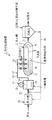
以下、本発明の汚水処理装置の第1の実施の形態の構成を図1を参照して説明する。
【0037】
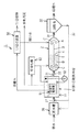
図1において、1は汚水処理装置としての高度処理装置であり、この高度処理装置1はオキシデーションディッチ法を用いている。また、この高度処理装置1は、断面長穴の有底筒状の反応槽としての反応タンクであるオイキシデーションディッチ用のディッチ槽2を備えている。そして、このディッチ槽2内の幅方向における中央部には、このディッチ槽2の長手方向に沿った仕切板3が取り付けられている。この仕切板3の長手方向における両端部は、ディッチ槽2の内側面よりも内側に位置している。また、この仕切板3の両端部とディッチ槽2の内側面との間には、この仕切板3の両側面とディッチ槽2の内側面との間の距離に等しい幅寸法の間隙が形成されている。
【0038】
すなわち、この仕切板3は、ディッチ槽2の内部に、このディッチ槽2の内側面に沿った無端状の流路としての無終端水路4を形成させる。言い換えると、この無終端水路4は、ディッチ槽2の内側面と仕切板3との間に形成された環状の循環流路である。ここで、この無終端水路4の内部には、所定量の汚水が流入されて貯留されている。そして、ディッチ槽2は、このディッチ槽2の無終端水路4内に貯留された汚水が、この無終端水路4の内周面に沿って所定の流速で循環するように構成されている。また、このディッチ槽2は、このディッチ槽2の無終端水路4内の汚水を好気性処理および嫌気性処理により生物学的に処理する。
【0039】
さらに、このディッチ槽2の無終端水路4の内部には、この無終端水路4内の汚水を曝気して酸素を供給する酸素供給手段としての曝気装置5が取り付けられている。この曝気装置5は、ディッチ槽2の幅方向における一方の無終端水路4内の長手方向における略中央部に設置されて、この無終端水路4内の汚水中に水没されている。具体的に、この曝気装置5は、ディッチ槽2の無終端水路4内の汚水中への酸素の溶解量を調整して、この無終端水路4内の汚水に酸素溶解量の異なる部分、すなわち好気性の部分である好気性領域Aと、無酸素状態の部分である嫌気性領域Bとを交互に設けさせて、この汚水を生物学的に処理する。
【0040】
ここで、このディッチ槽2の無終端水路4内における好気性領域Aは、この無終端水路4における曝気装置5よりも上流側の略半分の領域である。具体的に、この好気性領域Aは、無終端水路4内の活性汚泥により汚水を好気性処理して浄化する好気的雰囲気である。また、ディッチ槽2内の無終端水路4内における嫌気性領域Bは、この無終端水路4内の曝気装置5よりも下流側の酸素溶存量が好気性領域Bよりも少ない略半分の領域である。具体的に、この嫌気性領域Bは、分子状酸素(O2)がなく酸素化合物、すなわち硝酸塩(NO3)などが存在し、無終端水路4内の汚水を生物学的硝化脱窒にて窒素除去する無酸素雰囲気である。なお、この嫌気性領域Bは、曝気装置5の直上流部である。また、この嫌気性領域Bの最上流部は、季節や日時で生じる流入汚水の量的および質的変化により変動する。
【0041】
一方、このディッチ槽2の下流側には、このディッチ槽2の無終端水路4内へと汚水を供給して流入させる嫌気槽11が設置されている。この嫌気槽11は、略有底円筒状に構成されており、ディッチ槽2の外に設置されている。また、この嫌気槽11は、この嫌気槽11内に貯留された汚水を嫌気性微生物により嫌気性処理する。そして、この嫌気槽11の内部には、この嫌気槽11内に貯留された汚水を攪拌させて循環させる攪拌手段としての攪拌装置12が取り付けられている。
【0042】
そして、この攪拌装置12は、水中プロペラ型攪拌機などの潜水型攪拌機であり、嫌気槽11の上部に取り付けられた駆動手段としてのモータ13を備えている。このモータ13は、嫌気槽11内に一端部である下端部が挿入されたシャフト14の他端部である上端部に接続されており、このシャフト14を回転駆動させる。そして、このシャフト14の下端部には、プロペラ15が取り付けられている。このプロペラ15は、モータ13によるシャフト14の回転駆動によって、水平に回転駆動されて、嫌気槽11内に貯留された汚水を攪拌させて循環させる。
【0043】
さらに、この嫌気槽11の下流側には、この嫌気槽11内に貯留されて嫌気性処理された汚水を、ディッチ槽2の無終端水路4内へと供給して流入させる汚水供給手段としての汚水移送装置21が取り付けられている。この汚水移送装置21は、細長円筒状の汚水供給配管22を備えており、この汚水供給配管22の一端側である上流端は、嫌気槽11の下流側に接続されている。また、この汚水供給配管22の他端側である下流側は、複数、例えば3個に分岐されており、これら分岐された汚水供給配管22の下流端のそれぞれが供給口としての送水口23とされている。
【0044】
そして、これら各送水口23は、ディッチ槽2の無終端水路4における嫌気性領域Bの上流側に位置している。すなわち、これら各送水口23は、これら各送水口23から送水される汚水がディッチ槽2の無終端水路4内における汚水の嫌気性領域Bの極力上流部に自然流下で流入されるように構成されている。なお、必要な場合には、汚水供給配管22にポンプを取り付けて、この汚水供給配管22の各送水口23から汚水をポンプアップさせて送水させてもよい。
【0045】
さらに、この汚水供給配管22の各送水口23は、ディッチ槽2の長手方向である、このディッチ槽2の無終端水路4の流路方向Cに沿って等間隔に離間されて直線状に並設された状態で、このディッチ槽2の上方に配設されている。また、これら各送水口23それぞれの基端側の汚水供給配管22には、これら各送水口23を開閉させて、これら各送水口23から送水される汚水の送水量を切り替え可能あるいは調整可能とする開閉手段としてのバルブ24がそれぞれ取り付けられている。これらバルブ24は、各送水口23から送水される汚水を、手動あるいは自動で開閉可能なゲートあるいは弁機構などである。
【0046】
一方、嫌気槽11の上流側には、この嫌気槽へと供給されて流入される原水を貯留する貯留槽としての原水槽26が設置されている。この原水槽26は、略有底円筒状であり、この原水槽26内には汚水の原水が供給されて流入されて貯留されている。また、この原水槽26の下流側には、汚水供給手段としての汚水移送配管27の一端である上流端が接続されている。そして、この汚水移送配管27の他端である下流端は、嫌気槽11の上流側に接続されている。
【0047】
さらに、ディッチ槽2の下流側には、このディッチ槽2の無終端水路4内で嫌気性処理および好気性処理された汚水を排出させる汚水排出手段としての汚水排出配管31の一端である上流端が接続されている。具体的に、この汚水排出配管31の上流端は、ディッチ槽2の無終端水路4内に貯留された汚水の好気性領域Aの中間部に接続されている。
【0048】
そして、この汚水排出配管31の他端である下流端は、ディッチ槽2の無終端水路4内で嫌気性処理および好気性処理された汚水を処理水と返送汚泥とに固液分離する第1の固液分離手段としての沈殿槽である沈殿池32の上流側に接続されている。この沈殿池32は、略有底円筒状で、ディッチ槽2の下流側に設置されている。また、この沈殿池32の底部は、下方に向けて徐々に縮径したロート状に形成されている。そして、この沈殿池32は、ディッチ槽2の無終端水路4内で生物学的に処理された汚水から固形物としての汚泥を重力分離、すなわち沈殿させて、この汚泥が取り除かれた後の液体を処理水にして、この処理水を下流側から外部へと放出させる。
【0049】
さらに、この沈殿池32の底部中央には、汚泥返送手段としての汚泥返送配管33の一端である下流端が接続されている。この汚泥返送配管33の他端である下流端は、原水槽26と嫌気槽11との間に取り付けられた汚水移送配管27の中間部に接続されて連結されている。よって、この汚泥返送配管33は、沈殿池32内で沈殿して固液分離された汚泥を、汚水移送配管27を介して嫌気槽11の上流側に返送して供給させる。なお、この汚泥返送配管33の下流端を原水槽26に接続して、沈殿池32で分離した汚泥を原水槽26に返送させてもよい。
【0050】
次に、上記第1の実施の形態の高度処理装置を用いたオキシデーションディッチ法における汚水処理方法について説明する。
【0051】
まず、汚水は原水として原水槽26に流入され、この原水槽26内に貯留される。
【0052】
そして、この原水槽26内に貯留された汚水は、汚水移送配管27を介して嫌気槽11へと供給されて、この嫌気槽11内に貯留される。
【0053】
このとき、この嫌気槽11内に貯留された汚水は、攪拌装置12のプロペラ15の回転により攪拌されて、嫌気槽11内を循環する。同時に、この嫌気槽11内に貯留された汚水は、この嫌気槽11内の汚泥および嫌気性微生物により嫌気性処理される。
【0054】
この後、この嫌気槽11内で嫌気性処理された汚水は、汚水供給配管22へと自然流下し、この汚水供給配管22の各送水口23から、ディッチ槽2の無終端水路4内に貯留された汚水の嫌気性領域の上流部へと供給される。
【0055】
このとき、このディッチ槽2の無終端水路4内に供給されて貯留された汚水は、この無終端水路4内の曝気装置5にて曝気されるとともに、この無終端水路4内を循環する。
【0056】
この結果、この無終端水路4内における曝気装置5の下流側が好気性領域Aとなり、この無終端水路4内における曝気装置5の上流側が嫌気性領域Bとなる。
【0057】
そして、この無終端水路4内に貯留された汚水は、この無終端水路4内を循環しながら、この無終端水路4内の好気性領域Aにて好気性処理されるとともに、この無終端水路4内の嫌気性領域Bにて嫌気性処理される。
【0058】
さらに、ディッチ槽2の無終端水路4内で生物学的処理された汚水は、汚水排出配管31を介して沈殿池32へと供給されて、この沈殿池32内に貯留される。
【0059】
このとき、この沈殿池32内に貯留された汚水は、この沈殿池32内にて汚泥が沈殿して重力分離される。そして、この沈殿池32内で重力分離された汚泥は、この沈殿池32の底部から汚泥返送配管33を介して汚水移送配管27へと返送されて、嫌気槽11の上流側へと供給される。
【0060】
さらに、この沈殿池32内に貯留された汚水から汚泥が重力分離された後の液体が処理水となり、この処理水は沈殿池32の下流側から外部へと放出される。
【0061】
上述したように、上記第1の実施の形態によれば、嫌気槽11にて嫌気性処理された後の汚水を、ディッチ槽2の無終端水路4内の汚水の嫌気性領域Bの上流側に流入させた。この結果、このディッチ槽2の無終端水路4内の特定しにくい嫌気性領域Bの上流側に有機物を含有した汚水を供給できる。よって、このディッチ槽2の無終端水路4内の嫌気性領域Bで汚水の脱窒反応が効果的に生じるから、この無終端水路4内での汚水の嫌気性処理を効率良くできる。
【0062】
同時に、このディッチ槽2の無終端水路4内の好気性領域Aでの酸素溶存量を効率良く上昇できるので、この無終端水路4内での汚水の好気性処理をも効率良くできる。したがって、このディッチ槽2の無終端水路4内に貯留されて循環される汚水の硝化処理および脱窒処理のそれぞれをより効率良くできる。
【0063】
このとき、嫌気槽11内にて嫌気性処理された汚水を、汚水供給配管22の下流側を分岐させて、ディッチ槽2の無終端水路4の流路方向Cに沿って離間されて直線状に並設された複数の送水口23のそれぞれから、ディッチ槽2の無終端水路4内の嫌気性領域Bの上流側に送水させた。この結果、このディッチ槽2の無終端水路4内の特定しにくい嫌気性領域Bの上流側に、嫌気槽11にて嫌気性処理されて有機物を含有した汚水を効率良く供給できる。よって、このディッチ槽2の無終端水路4内での汚水の脱窒処理を簡単な構成で確実に効率良くできる。
【0064】
また、既設のオキシデーションディッチ法を用いた処理施設を利用して、生物学的窒素およびリン除去をする際にも、比較的簡単な設備の改造をするだけで実施できる。
【0065】
なお、このディッチ槽2の無終端水路4内で汚水の生物学的リン除去をする場合には、このディッチ槽2の無終端水路4内の嫌気性領域Bで微生物が有機物を摂取すると同時にリンを放出する。したがって、このディッチ槽2の無終端水路4内の好気性領域Aで、微生物がリンを過剰に摂取するように構成すればよい。
【0066】
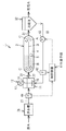
次に、本発明の第2の実施の形態を図2を参照して説明する。
【0067】
この図2に示す高度処理装置1は、基本的には図1に示す高度処理装置1と同様であるが、制御手段としての制御装置41を設け、この制御装置41にて汚泥返送配管33を介して沈殿池32から嫌気槽11へと返送される汚泥の返送量を調整したものである。
【0068】
そして、この制御装置41は、汚泥返送配管33にて嫌気槽11へと返送される汚泥の流量や濃度を測定する汚泥流量測定手段としての返送汚泥流量計である濃度計42を備えている。この濃度計42は、汚泥返送配管33の下流側に取り付けられている。また、この濃度計42は、制御装置41にて制御されて汚泥返送配管33を介した汚泥の返送量や、この汚泥の濃度などを計測する。
【0069】
さらに、この汚泥返送配管33には、この汚泥返送配管33による汚泥の返送量を調整する汚泥移送手段としての返送汚泥ポンプ43が取り付けられている。この返送汚泥ポンプ43は、汚泥返送配管33における濃度計42の上流側に取り付けられている。そして、この返送汚泥ポンプ43は、この返送汚泥ポンプ43により汚泥返送配管33を介した汚泥の返送量が制御装置41により制御されている。
【0070】
また、原水槽26と嫌気槽11との間の汚水移送配管27には、この汚水移送配管27を介して原水槽26から嫌気槽11へと供給される汚水の流量を測定する汚水流量測定手段としての原水流量計44が取り付けられている。よって、制御装置41は、原水流量計44にて計測される嫌気槽11への汚水の流量値と、濃度計42にて計測される嫌気槽11への汚水の流量値とのそれぞれに基づいて返送汚泥ポンプ43の回転数や吐出側の図示しない自動弁などを制御して、この返送汚泥ポンプ43による汚泥の返送量を調整する。
【0071】
すなわち、オキシデーションディッチによる処理方法が適用されている汚水処理場では、原水の質的および量的に季節や日間の変動が大きい。このため、ディッチ槽2と嫌気槽11とを組み合わせて、この嫌気槽11にて生物学的にリンを放出させる場合には、この嫌気槽11でのリンの放出には有機物が必要であるが、この嫌気槽11への汚水の供給量の変動が大きいと、この嫌気槽11内に貯留される汚水中からのリンの放出のために生化学的酸素要求量(Biochemical Oxygen Demand:BOD)が不足してしまうおそれがある。
【0072】
また、この嫌気槽11に沈殿池32で重力分離した汚泥を返送することにより、この嫌気槽11での汚水からのリンの放出と、ディッチ槽2の無終端水路4内の好気性領域Aでのリンの過剰摂取とを可能にする微生物が訓養される。さらに、沈殿池32から返送される汚泥には、リンを除去する微生物以外にBODを摂取する微生物も存在しているため、嫌気槽11内においてリンを放出させるために必要なBOD源が不足してしまう。
【0073】
このため、嫌気槽11へと供給される汚水の供給量を原水流量計44で計測しつつ、この嫌気槽11へと返送される汚泥の流量を濃度計42で計測し、これら原水流量計44および濃度計42それぞれの計測値に基づいて、制御装置41にて返送汚泥ポンプ43による嫌気槽11への汚泥、すなわち微生物の返送量を調整することにより、この嫌気槽11への適正な汚泥の返送量を保つことができる。よって、この嫌気槽11内に貯留される汚水のBODが過剰に減少することを調整できるから、この嫌気槽11でのリン放出磯能を維持できる。
【0074】
この結果、この嫌気槽11での汚水の嫌気性処理やリン除去のために必要な汚泥の返送量を調整できるから、この嫌気槽11への汚水の供給量の日間変動が大きい場合や、この嫌気槽11へと返送される汚泥の微生物量が多い場合などでも、この嫌気槽11での汚水の嫌気性処理やリン除去などの生物学的処理を確実に効率良くできる。このとき、制御装置41で、実際に返送されている汚泥の返送量や濃度などを濃度計42にて計測し、この汚泥の返送量が適性であるかの情報も加味することにより、嫌気槽11への汚泥の返送量の制御がより適性にできる。
【0075】
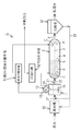
次に、本発明の第3の実施の形態を図3を参照して説明する。
【0076】
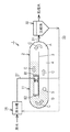
この図3に示す高度処理装置1は、基本的には図1に示す高度処理装置1と同様であるが、嫌気槽11にて処理された汚水を第2の固液分離手段としての固液分離装置51で汚泥を固液分離した後の汚水をディッチ槽2の無終端水路4内の嫌気性領域Bへと供給させて流入させたものである。
【0077】
そして、この固液分離装置51は、嫌気槽11内の嫌気性微生物を含んだ汚水を固液分離する。すなわち、固液分離装置51は、嫌気槽11にて嫌気性処理などされた後の汚水が供給され、この汚水から固液分としての固形物である汚泥を固液分離する。そして、この固液分離装置51にて固液分離された汚泥は、この汚泥を可溶化させてBOD源を生成させる可溶化手段としての可溶化槽52へと供給される。
【0078】
この可溶化槽52は、固液分離装置51にて固液分離された後の汚泥の少なくとも一部を可溶化させて、この汚泥から微生物が分解可能な有機物を溶出させたり、この汚泥を微生物が分解可能となるまで分解させる。さらに、この可溶化槽52にて可溶化された汚泥は、嫌気槽11へと返送されて、この嫌気槽11内に供給され、この嫌気槽11内での汚水の嫌気性処理やリン除去のためのBOD源として利用される。
【0079】
また、固液分離装置51にて固液分離された汚泥のうち、可溶化槽52にて可溶化されない汚泥は、この可溶化槽52へと供給されずに、余剰汚泥として外部へと引き抜かれて放出される。ここで、固液分離装置51にて固液分離した汚泥の全部を、可溶化槽52へと供給して、この可溶化槽52にて可溶化させてもよい。
【0080】
この結果、嫌気槽11にて嫌気性処理などされた汚水から固液分離装置51にて汚泥を固液分離し、この汚泥を可溶化槽52にて可溶化させて、嫌気槽11でのリンの放出の際に必要なBOD源を生成させてから、この汚泥を嫌気槽11へと返送して添加させることにより、この嫌気槽11での汚水のリン除去に必要なBOD源を供給できる。
【0081】
したがって、この嫌気槽11におけるリン放出の有機物不足を捕捉できるので、この嫌気槽11での汚水のリン除去をより効率良くできる。また、この嫌気槽11でリン除去をすることにより、この嫌気槽11内に生成される汚泥のリン含有量を少なくできるから、この汚泥を可溶化槽52にて可溶化させた際にリンの発生量が少なくなり、ディッチ槽2でのリン負荷の増加を抑制できる。
【0082】
また、固液分離装置51にて固液分離された後の汚泥を可溶化槽52へと供給する前の工程で、この可溶化槽52での汚泥の可溶化量に応じて、この汚泥の一部を余剰汚泥として引き抜いた。この結果、嫌気槽11での汚泥の発生量を減少できるとともに、この嫌気槽11内にて成形される嫌気性汚泥を処理する際に生じるリンの放出量も少なくできるから、この嫌気槽11へと返送される汚泥による汚水負荷への影響などの障害を少なくできる。
【0083】
なお、必要な場合には、可溶化槽52にて可溶化された汚泥を、ディッチ槽2の無終端水路4内に貯留された汚水の嫌気性領域Bに供給させて、このディッチ槽2の無終端水路4の嫌気性領域Bでの汚水の脱窒反応に利用することもできる。
【0084】
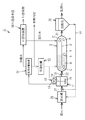
次に、本発明の第4の実施の形態を図4を参照して説明する。
【0085】
この図4に示す高度処理装置1は、基本的には図3に示す高度処理装置1と同様であるが、固液分離装置51にて汚泥を固液分離した後の汚水中のリンを、リン回収手段としてのリン回収装置56にて回収させたものである。ここで、このリン回収装置56にてリンが回収された後の汚水は、脱リン水とされて、ディッチ槽2の無終端水路4内の好気性領域Aへと供給され、このディッチ槽2の無終端水路4内で処理される。
【0086】
また、このリン回収装置56には、固液分離装置51にて固液分離された後の分離水である汚水が供給されて、この汚水中のリンをアパタイト晶析法によりリン回収物であるヒドロキシアパタイトとして固定させて回収する。具体的に、このリン回収装置56は、固液分離装置54にて汚泥が分離された後の液体である汚水にカルシウムイオンを加えて、この汚水中のリン酸イオンをヒドロキシアパタイトとして晶析させて除去して、この汚水の脱リンをする。
【0087】
この結果、嫌気槽11にて処理された後の汚水は比較的リンの濃度が高いので、この嫌気槽11にて処理された汚水から固液分離装置51にて固液分離された汚水に、リン回収装置56にてカルシウムイオンを加えて、この汚水中のリン酸イオンをヒドロキシアパタイトとして晶析させて除去させた。よって、ディッチ槽2にて処理する前の段階で、汚水からリンを効率良く晶析させて回収できる。
【0088】
このとき、リン回収装置56にて回収した晶析物であるヒドロキシアパタイトは純度が高く、このリン回収装置56はリン回収技術として位置付けられている。このため、このリン回収装置56にて回収したヒドロキシアパタイトをそのまま肥料として利用することも可能である。
【0089】
次に、本発明の第5の実施の形態を図5を参照して説明する。
【0090】
この図5に示す高度処理装置1は、基本的には、図4に示す高度処理装置1と同様であるが、固液分離装置51を浸漬膜方式として、この固液分離装置51を上側が閉塞されて密閉された嫌気槽11内に収納させたものである。
【0091】
そして、この固液分離装置51は、嫌気槽11内の汚水を膜分離にて濾過する膜分離手段としての膜分離装置である。また、嫌気槽11内における固液分離装置の下方には、この固液分離装置51の図示しない浸漬膜を洗浄して、この浸漬膜の目詰まりなどを防止する第1の散気手段としての散気装置61が配設されている。
【0092】
この散気装置61は、嫌気槽11外に設置された送気手段としてのブロワ62に接続されており、このブロワ62から吐出されて供給される気体としてのガスを嫌気槽11内に散気させる。すなわち、このブロワ62は、嫌気槽11内の汚水の液面状の空気よりも酸素含有量が少ないガスを収集して吐出させて、このガスを散気装置61から固液分離装置51の浸透膜の下方に散気して、この浸漬膜を洗浄し、この浸漬膜の閉塞を防止する。
【0093】
この結果、嫌気槽11内の汚水の脱リン対象水を抽出する方法の一つとして、固液分離装置51を浸漬膜方式の膜分離装置とし、この固液分離装置51を、上側が閉塞されて密閉された嫌気槽11内に浸漬させるとともに、この嫌気槽11内に散気装置61を取り付けて、この散気装置61にて嫌気槽11内の汚水の液面状の酸素含有量の少ないガスを固液分離装置51の浸漬膜に散気させた。
【0094】
このため、この散気装置61からのガスの散気により固液分離装置51の浸漬膜が洗浄されて、この浸漬膜の目詰まりを防止できる。よって、この嫌気槽11内での固液分離装置51による膜分離を効率良くできるとともに、この嫌気槽11内の汚水を循環させて攪拌できるので、この嫌気槽11内の攪拌装置12を小さく、さらには不要にできる。
【0095】
さらに、この嫌気槽11の上側を閉塞して密閉させ、この嫌気槽11内の汚水の液面上に充満した酸素溶存量の少ないガスを、この嫌気槽11内の汚水に散気装置61にて散気させた。このため、この嫌気槽11内での汚水の嫌気性処理を効率良くを維持しつつ、この嫌気槽11内の汚水を循環させて攪拌できる。また、固液分離装置51を嫌気槽11内に浸漬させたため、この固液分離装置51を設置する敷地が不要となる。
【0096】
次に、本発明の第6の実施の形態を図6を参照して説明する。
【0097】
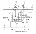
この図6に示す高度処理装置1は、基本的には図5に示す高度処理装置1と同様であるが、ディッチ槽2の無終端水路4内を階段状の仕切体としての間仕切り壁66にて仕切り、この間仕切り壁66上に曝気装置5を設置させたものである。
【0098】
そして、この間仕切り壁66は、ディッチ槽2の無終端水路4内を、この無終端水路4の流路方向Cに対して閉塞し、この無終端水路4の幅方向に沿って取り付けられている。ここで、この間仕切り壁66は、ディッチ槽2の無終端水路4内における嫌気性領域Bの下流側と好気性領域Aの上流側とを仕切る仕切り板である。すなわち、この間仕切り壁66よりも下流側の無終端水路4内が好気性領域Aとなり、この間仕切り壁66よりも上流側の無終端水路4内が嫌気性領域Bとなる。
【0099】
さらに、この間仕切り壁66は、ディッチ槽2の無終端水路4内の上側を閉塞する矩形平板状の上側閉塞板67を備えている。この上側閉塞板67は、ディッチ槽2の無終端水路4の幅方向および上下方向のそれぞれに平面方向を沿わせた状態で取り付けられており、この無終端水路4内における上側の約3分の2の閉塞している。
【0100】
また、この上側閉塞板67の下端縁には、ディッチ槽2の無終端水路4の流路方向Cに沿った平面方向を有する矩形平板状の載置板68の一端縁が取り付けられている。この載置板68は、ディッチ槽2の無終端水路4内における上側閉塞板67の上流側に取り付けられており、このディッチ槽2の無終端水路4内の一部を水平に閉塞している。
【0101】
さらに、この載置板68の他端縁には、ディッチ槽2の無終端水路4の下側の約3分の1を閉塞する矩形平板状の下側閉塞板69の上端縁が接続されている。この下側閉塞板69は、上側閉塞板67の平面方向に沿った平面方向を有している。また、この下側閉塞板69は、ディッチ槽2の無終端水路4内における上側閉塞板67の上流側に取り付けられている。したがって、このディッチ槽2の無終端水路4の内部は、間仕切り壁66によって、この無終端水路4の流路方向Cに向けて階段状に閉塞されている。
【0102】
そして、この間仕切り壁66の載置板68上には、いわゆるドラフトチューブ型あるいは軸流ポンプ型である曝気装置5が設置されている。この曝気装置5は、上下方向に沿った軸方向を有する略円筒状の胴体部としてのドラフトチューブ71を備えている。このドラフトチューブ71は、下端部が間仕切り壁66の載置板68上に接続されており、ディッチ槽2の無終端水路4内に配設されている。
【0103】
ここで、この間仕切り壁66の載置板68の中央部には、ドラフトチューブ71の下端部をディッチ槽2の無終端水路4の好気性領域Aに連通させる図示しない開口部としての貫通孔が形成されている。この貫通孔は、ドラフトチューブ71の内径寸法に略等しい内径寸法を有している。また、このドラフトチューブ71の上端側には、このドラフトチューブ71の軸方向に沿って上側に向けて拡開した拡開部としての拡径開口部72が形成されている。
【0104】
そして、このドラフトチューブ71の内部には、このドラフトチューブ71内に酸素を供給する第2の散気手段としての円環状の散気管73が取り付けられている。この散気管73は、ドラフトチューブ71内において、このドラフトチューブ71の同心状に取り付けられている。また、この散気管73は、ディッチ槽2の無終端水路4よりも上方に設置された送風手段である酸素供給ブロワ74から吐出される酸素を含んだ気体であるガスが供給されて、この空気をディッチ槽2の無終端水路4内の汚水に散気する。
【0105】
具体的に、この散気管73は、酸素供給ブロワ74から吐出されて供給される酸素を含んだガスをドラフトチューブ71の内部に散気させて、このガス中の酸素を汚水中に溶解させて、この酸素が溶解された汚水を、ドラフトチューブ71の内部から間仕切り壁66の貫通孔を介して、ディッチ槽2の無終端水路4内の好気性領域Aへと循環させる。
【0106】
一方、このドラフトチューブ71の上方には、駆動手段としての駆動装置75が設置されている。この駆動装置75は、ディッチ槽2の無終端水路4よりも上方に取り付けられた矩形平板状の設置台76上に設置されている。そして、この駆動装置75は、一端部である下端部がドラフトチューブ71内へと挿入されたシャフトとしての回転軸である細長円柱状の主軸77の他端部である上端部が接続されている。この主軸77は、駆動装置75にて周方向に向けて回転駆動される。
【0107】
ここで、この主軸77は、ドラフトチューブ71の中心部に同心状である軸心上に挿入されて配設されている。そして、この主軸77の下端部には、ドラフトチューブ71内の汚水を下方へと送水させて、ディッチ槽2の無終端水路4内の汚水を循環させる回転部としての送水手段であるインペラ78が取り付けられている。このインペラ78は、ドラフトチューブ71内において、このドラフトチューブ71の径方向に沿って回転可能に配設されている。そして、このインペラ78は、駆動装置75による主軸77の回転駆動により、ドラフトチューブ71内の汚水を上方から下方へと流出させる。
【0108】
また、このインペラ78は、ドラフトチューブ71内において散気管73の上方である上流側に設置されている。言い換えると、この散気管73は、ドラフトチューブ71内におけるインペラ78よりも下方である下流側に設置されている。したがって、このインペラ78は、このインペラ78の回転により散気管73から散気されるガスを剪断して、このガスをドラフトチューブ71内の汚水に溶解させつつ、このインペラ78の回転による送水力によりドラフトチューブ71内の汚水をディッチ槽2の無終端水路4内における好気性領域Aへと循環させて、このディッチ槽2の無終端水路4内の汚水の循環流を形成させる。
【0109】
この結果、ディッチ槽2の無終端水路4内に設置した曝気装置5のドラフトチューブ71内に、このドラフトチューブ71内の汚水を下方へと流出させるインペラ78を回転可能に配設するとともに、このドラフトチューブ71内におけるインペラ78の下方に、このドラフトチューブ71内の汚水に酸素を含んだガスを散気する散気管73を配設して、この曝気装置5の送水機構と散気機構とを別個に構成した。
【0110】
したがって、これらインペラ78の回転速度および散気管73からのガスの散気量を調整することにより、ディッチ槽2の無終端水路4内での汚水の循環流速と酸素供給とのそれぞれが別個に調整可能となる。このため、このディッチ槽2の無終端水路4内に貯留される汚水負荷に応じて、このディッチ槽2の無終端水路4内の汚水への酸素供給量を調整できる。
【0111】
よって、ドラフトチューブ71内でのインペラ78の回転による汚水の送水とは別に、散気管73から汚水に酸素供給ができるので、曝気装置5が1台だけであっても、ディッチ槽2の無終端水路4内へと流入される汚水の水量や水質の変動に関わらず、このディッチ槽2の無終端水路4内に好気性領域Aと嫌気性領域Bとを交互に形成できる。
【0112】
このため、このディッチ槽2の無終端水路4内の汚水に酸素溶解量の異なる好気性領域Aと嫌気性領域Bとを時間的あるいは空間的に容易に形成できるから、このディッチ槽2の無終端水路4内での汚水の生物学的硝化脱窒処理をより効率良く容易にできる。
【0113】
また、このディッチ槽2の無終端水路4内を階段状の間仕切り壁66にて間仕切り、この間仕切り壁66上に設置した曝気装置5にて無終端水路4内の汚水を循環させたことにより、この無終端水路4の底部での汚水の流速を確保できる。よって、この無終端水路4内での汚水の循環をより確実にでき、この無終端水路内での汚泥の堆積などを防止できるから、この無終端水路4内での汚水の生物学的硝化脱窒処理をより確実に効率良くできる。
【0114】
次に、本発明の第7の実施の形態を図7を参照して説明する。
【0115】
この図7に示す高度処理装置1は、基本的には図6に示す高度処理装置1と同様であるが、ディッチ槽2の無終端水路4内を間仕切り壁66にて仕切らずに、この無終端水路4内に設置された曝気装置5のドラフトチューブ71の下端側を延出させて、このドラフトチューブ71の下端側をディッチ槽2の無終端水路4の流路方向Cにおける下流側に向けて90゜湾曲させたものである。
【0116】
そして、この曝気装置5のドラフトチューブ71の下端側は、ディッチ槽2の無終端水路4内の底部近傍まで突出している。また、このドラフトチューブ71の下端側は、無終端水路4の下流側に向けてエルボ状に湾曲している。すなわち、このドラフトチューブ71は、このドラフトチューブ71内のインペラ78を回転させることにより、このドラフトチューブ71の上側から内部に流入した汚水が流れる方向を水平方向に変換して、ディッチ槽2の無終端水路4内の汚水に循環流を形成させる。
【0117】
この結果、ディッチ槽2の無終端水路4内に設置した曝気装置5のドラフトチューブ71内のインペラ78を回転させることにより、このドラフトチューブ71内の汚水が、ディッチ槽2の無終端水路4の下流側に向けて送水されて、この無終端水路4内の汚水に循環流が形成されるので、上記第8の実施の形態と同様の作用効果を奏することができる。
【0118】
次に、本発明の第8の実施の形態を図8を参照して説明する。
【0119】
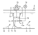
この図8に示す高度処理装置1は、基本的には図7に示す高度処理装置1と同様であるが、ディッチ槽2の無終端水路4の内部に嫌気槽11を設置させたものである。
【0120】
そして、この嫌気槽11は、断面細長矩形状の略有底角柱状であり、ディッチ槽2の無終端水路4の流路方向Cに長手方向を沿わせた状態で、この無終端水路4内における嫌気性領域Bの略中間部に配設されている。また、この嫌気槽11は、この嫌気槽11の幅方向における一側面をディッチ槽2の無終端水路4内の仕切板3の一側面に接触させた状態で、この無終端水路4内に形成されている。さらに、この嫌気槽11は、ディッチ槽2の無終端水路4における一方の水路の幅寸法の約2分の1程度の幅寸法を有している。
【0121】
また、この嫌気槽11の長手方向における一端側である上流側には、ディッチ槽2の無終端水路4内を循環する汚水が流入される開口部としての細長矩形状の流入口81が形成されている。この流入口81は、嫌気槽11の上流側の側面の下部に設けられている。また、この流入口81は、ディッチ槽2の無終端水路4の底部近傍を循環する汚水の下層部分が流入するように構成されている。
【0122】
さらに、この嫌気槽11の長手方向における他端側である下流側には、この嫌気槽11内にて嫌気性処理などされた汚水が流出される開口部としての細長矩形状の流出口82が形成されている。この流出口82は、嫌気槽11の下流側の側面の上部に設けられている。また、この流出口82は、嫌気槽11内にて嫌気性処理などされた汚水の上層部分が、この嫌気槽11の内部からディッチ槽2の無終端水路4内へと流出するように構成されている。
【0123】
この結果、このディッチ槽2の無終端水路4内に嫌気槽11を設置させたため、このディッチ槽2の無終端水路4内での汚水の循環を利用して、嫌気槽11の底部での汚水の流速を容易に確保でき、この嫌気槽11内の汚水を攪拌できる。このため、この嫌気槽11内での汚泥の沈降を防止できるとともに、ディッチ槽2の無終端水路4内の汚水への過剰な酸素供給による有機物不足を容易に調整できる。
【0124】
同時に、嫌気槽11の底部での汚水の流速を確保するためには、ディッチ槽2の無終端水路4内に設置された曝気装置5のインペラ78の回転数を変化させることにより対応できる。また、このディッチ槽2の無終端水路4内へと供給される汚水の水量や水質の変動に対しては、酸素供給ブロワ74からの酸素の送気量を変化させることにより対応できる。
【0125】
さらに、汚水を供給する際や、汚泥を返送する際の送水力を利用して、嫌気槽11内の汚水を攪拌させてもよい。なお、必要な場合には、この嫌気槽11の内部に最低限の攪拌装置12を取り付けて、この嫌気槽11内の汚水を攪拌させてもよい。また、沈殿池32からの汚泥の返送を嫌気槽11ではなく原水槽26へと返送させて、嫌気槽11でのリン放出の負荷を軽減させてもよい。
【0126】
【発明の効果】
請求項1記載の汚水処理装置によれば、反応槽の無端状の流路内の汚水中に酸素供給手段にて酸素を供給して、この流路内の汚水に酸素溶解量の異なる部分を設けさせるとともに、この反応槽の流路内の汚水における酸素溶存量の少ない部分に、汚水を嫌気性処理する嫌気槽にて嫌気性処理された汚水を流入させることにより、反応槽の流路内の汚水における酸素溶存量の少ない部分での嫌気性処理を効率良くできるので、この反応槽の流路内の汚水の脱窒処理をより効率良くできる。
【0127】
請求項2記載の汚水処理装置によれば、反応槽にて処理された汚水を第1の固液分離手段にて処理水と汚泥とに固液分離し、この固液分離された汚泥を嫌気槽の内部あるいは上流側のいずれかに返送する際に、嫌気槽への汚水の流量を制御手段にて測定し、この嫌気槽へと返送される汚泥の流量を調整することにより、嫌気槽内での汚水の処理に必要な汚泥の返送量を調整できるので、この嫌気槽への汚水の供給量の変動が大きい場合でも、この嫌気槽での汚水の処理を効率良くできる。
【0128】
請求項3記載の汚水処理装置によれば、嫌気槽内の嫌気性微生物を含んだ汚水を第2の固液分離手段にて固液分離した後、この第2の固液分離手段にて固液分離した固形物の少なくとも一部から、微生物が分解可能な有機物を可溶化手段にて溶出させ、この可溶化手段にて有機物が溶出された後の汚水を嫌気槽および反応槽のいずれかに供給することにより、これら嫌気槽および反応槽のいずれかでの汚水の処理に必要な有機物を供給できるから、これら嫌気槽および反応槽いずれかでの汚水処理をより効率良くできる。
【0129】
請求項4記載の汚水処理装置によれば、第2の固液分離手段にて分離した固形物の少なくとも一部を微生物が分解可能となるまで可溶化手段で分解することにより、この可溶化手段にて分解された後の汚水の嫌気槽および反応槽のいずれかへの供給で、これら嫌気槽および反応槽のいずれかでの汚水の処理に必要な有機物を供給できるから、これら嫌気槽および反応槽いずれかでの汚水処理をより効率良くできる。
【0130】
請求項5記載の汚水処理装置によれば、第2の固液分離手段にて分離した固形物の一部を排出させ、この固形物の残りを可溶化手段にて処理させることにより、第2の固液分離手段にて分離した固形物の発生量を減量でき、反応槽および嫌気槽のいずれかへの固形物の供給量を減量できる。
【0131】
請求項6記載の汚水処理装置によれば、嫌気槽内の嫌気性微生物を含んだ排水を第2の固液分離手段にて固液分離した後、この第2の固液分離手段にて固形物が分離された汚水にリン回収手段にてカルシウムイオンを加えて、この汚水中のリン酸イオンをヒドロキシアパタイトとして晶析させて除去させることにより、嫌気槽内の汚水は比較的リン濃度が高いから、この汚水中からのリンを効率良く晶析できる。
【0132】
請求項7記載の汚水処理装置によれば、嫌気槽内に配設された膜分離手段で嫌気槽内の汚水を濾過し、この嫌気槽内における膜分離手段の下方に配設した第1の散気手段で嫌気槽内の汚水の液面の空気よりも酸素含有量の少ない気体を散気して膜分離手段を洗浄することにより、嫌気槽内での汚水の嫌気性処理を維持させつつ、この嫌気槽内の汚水を循環でき、この嫌気槽内の膜分離手段による汚水の固液分離を効率良くできる。
【0133】
請求項8記載の汚水処理装置によれば、反応槽の流路内に配設された上下方向に沿った軸方向を有する筒状の胴体部内に回転可能に回転部を配設し、この回転部にて胴体部内の汚水を上方から下方へと流出させると同時に、この胴体部内における回転部より下方に、酸素を含んだ気体を散気する第2の散気手段を配設して酸素供給手段としたことにより、反応槽内の汚水の循環流速と酸素供給とが別個に調整可能となるので、この反応槽への負荷に応じて、この反応槽内の汚水への酸素供給量を調整でき、この反応槽内の汚水に酸素溶解量の異なる部分を設けやすくなるから、この反応槽での汚水の生物学的処理をより効率良くできる。
【0134】
請求項9記載の汚水処理装置によれば、嫌気槽にて処理された汚水を複数の供給口にて反応槽の流路内における酸素溶解量が少ない部分の上流側に供給することにより、反応槽の流路内での汚水の嫌気性処理をより効率良くできるから、この汚水の脱窒反応をより効率良くできる。
【0135】
請求項10記載の汚水処理装置によれば、反応槽の流路内に嫌気槽を配設することにより、嫌気槽内での汚泥の沈降を防止でき、この嫌気槽内での汚水の流速を確保できるから、反応槽での過剰な酸素供給による有機物不足を容易に調整できる。
【0136】
請求項11記載の汚水処理方法によれば、反応槽の無端状の流路内の汚水中に酸素を供給してこの流路内の汚水に酸素溶解量が異なる部分を設けると同時に、この反応槽の流路内の汚水における酸素溶存量の少ない部分に、嫌気槽にて嫌気性処理された汚水を流入させることにより、反応槽の流路内の汚水における酸素溶存量の少ない部分での嫌気性処理を効率良くできるので、この反応槽の流路内の汚水の脱窒処理をより効率良くできる。
【図面の簡単な説明】
【図1】本発明の汚水処理装置の第1の実施の形態を示す概略説明図である。
【図2】本発明の第2の実施の形態の汚水処理装置を示す概略説明図である。
【図3】本発明の第3の実施の形態の汚水処理装置を示す概略説明図である。
【図4】本発明の第4の実施の形態の汚水処理装置を示す概略説明図である。
【図5】本発明の第5の実施の形態の汚水処理装置を示す概略説明図である。
【図6】本発明の第6の実施の形態の汚水処理装置の一部を示す概略説明図である。
【図7】本発明の第7の実施の形態の汚水処理装置の一部を示す概略説明図である。
【図8】本発明の第8の実施の形態の汚水処理装置を示す概略説明図である。
【符号の説明】
1 汚水処理装置としての高度処理装置
2 反応槽としてのディッチ槽
4 流路としての無終端水路
5 酸素供給手段としての曝気装置
11 嫌気槽
23 供給口としての送水口
32 第1の固液分離手段としての沈殿池
41 制御手段としての制御装置
51 第2の固液分離手段としての固液分離装置
52 可溶化手段としての可溶化槽
56 リン回収手段としてのリン回収装置
61 第1の散気手段としての散気装置
71 胴体部としてのドラフトチューブ
73 第2の散気手段としての散気管
78 回転部としてのインペラ[0001]
TECHNICAL FIELD OF THE INVENTION
TECHNICAL FIELD The present invention relates to a sewage treatment apparatus and a sewage treatment method in which a portion having a different amount of dissolved oxygen is provided in sewage in an endless flow path of a reaction tank.
[0002]
[Prior art]
Conventionally, this type of sewage treatment apparatus has used a sewage treatment method using an oxidation ditch, and is one of the representative methods of domestic sewage treatment such as small-scale sewage, particularly sewage. Rather, it is widely used in small and medium municipalities.
[0003]
The sewage treatment apparatus includes a raw water tank into which raw water as sewage flows, and the raw water flowing into the raw water tank is pumped up, and is an oxidation tank which is a reaction tank having an endless flow path. It flows into the flow path of the ditch tank for ditch. Activated sludge flows into the flow channel of the ditch tank. Then, the raw water that has flowed into the flow path of the ditch tank is purified by activated sludge, then gravity-separated into sludge and treated water, and the treated water is released.
[0004]
In recent years, due to the problem of eutrophication in closed water bodies, advanced treatment for removing nitrogen and phosphorus has been demanded in wastewater treatment facilities. In the treatment by the conventional sewage treatment method using the oxidation ditch method for removing nitrogen, the interior of the ditch tank is temporally or spatially aerobic atmosphere and molecular oxygen O2Not available but oxygen compound NO3Nitrogen is removed by biological nitrification and denitrification in an oxygen-free atmosphere in which nitric acid and the like are present.
[0005]
Specifically, the ventilation to the air diffuser in the ditch tank is intermittently performed, or the length of the circulation channel of the ditch tank is increased. Alternatively, one of the two aerators installed in the ditch tank may be submerged in the ditch tank.
[0006]
As for the removal of phosphorus, it is not usually actively removed. However, when phosphorus is removed by a treatment using a sewage treatment method using an oxidation ditch, the wastewater in the flow path of the ditch tank is not included. A coagulant such as PAC (Poly Aluminum Chloride) is added to the inside of the sewage to reduce the PO.4 3--Remove P as coagulated sludge.
[0007]
In this type of sewage disposal method using an oxidation ditch, an anaerobic tank functioning as a flow rate adjustment tank is provided upstream of the flow path of the ditch tank for the oxidation ditch. This anaerobic tank contains molecular oxygen O2And NO that is an oxygen compound3It is a completely anaerobic tank without nitric acid. Then, raw water and returned sludge are caused to flow into the anaerobic tank, and phosphorus is released from the activated sludge. Thereafter, biological dephosphorization is performed by excessively ingesting phosphorus in the channel of the ditch tank (for example, see Patent Document 1).
[0008]
Further, in this type of sewage disposal method using an oxidation ditch, a phosphorus release tank acting as an anaerobic tank is provided upstream of a ditch tank for the oxidation ditch and at a preceding stage. Then, the raw water, which is the sewage flowing into and out of each of the flow path of the ditch tank and the phosphorus release tank, is linked to perform biological dephosphorization of the raw water (for example, see Patent Document 2).
[0009]
[Patent Document 1]
JP-A-7-290083 (page 2-3, FIG. 1)
[0010]
[Patent Document 2]
JP-A-2002-186989 (page 3-6, FIG. 1)
[0011]
[Problems to be solved by the invention]
However, in the sewage disposal method using the oxidation ditch described in
[0012]
Further, in the sewage disposal method using the oxidation ditch described in Patent Document 2, process water containing an organic substance is introduced from the phosphorus release tank into the flow path of the ditch tank to compensate for the shortage of the organic substance. However, the position where the process water containing the organic matter is introduced is downstream of the aeration device installed in the flow path of the ditch tank, that is, immediately after the organic matter is removed. For this reason, the dissolved oxygen dissolved in the sewage by the aeration device may be drawn into the phosphorus release tank, and the treatment of the sewage in the flow path of the ditch tank is not efficient. At the same time, since a submersible stirrer such as an underwater propeller stirrer is required inside the phosphorus discharge tank, there is a problem that the apparatus for recovering phosphorus from wastewater is large.
[0013]
The present invention has been made in view of such a point, and an object of the present invention is to provide a sewage treatment apparatus and a sewage treatment method that can more efficiently treat sewage in a reaction tank.
[0014]
[Means for Solving the Problems]
The sewage treatment apparatus according to
[0015]
Then, oxygen is supplied to the sewage in the endless flow path of the reaction tank by the oxygen supply means, and the sewage in the flow path is provided with a portion having a different amount of dissolved oxygen. Further, the sewage that has been anaerobically treated in the anaerobic tank for anaerobically treating the sewage flows into a portion of the sewage in the flow path of the reaction tank where the amount of dissolved oxygen is small. As a result, the anaerobic treatment in the portion of the sewage in the flow path of the reaction tank where the amount of dissolved oxygen is small becomes efficient. Therefore, the denitrification treatment of the sewage in the channel of the reaction tank can be performed more efficiently.
[0016]
The sewage treatment apparatus according to claim 2 is the sewage treatment apparatus according to
[0017]
Then, the wastewater treated in the reaction tank is separated into treated water and sludge by the first solid-liquid separation means, and the solid-liquid separated sludge is placed inside the anaerobic tank or on the upstream side. I will send it back. At this time, the flow rate of the sewage to the anaerobic tank is measured by the control means, and the flow rate of the sludge returned to the anaerobic tank is adjusted. As a result, the amount of sludge returned for the treatment of sewage in the anaerobic tank can be adjusted. Therefore, even when the amount of supply of sewage to the anaerobic tank varies greatly, the treatment of sewage in the anaerobic tank is large. Can be done efficiently.
[0018]
The sewage treatment apparatus according to
[0019]
Then, the wastewater containing the anaerobic microorganisms in the anaerobic tank is subjected to solid-liquid separation by the second solid-liquid separation means. Thereafter, an organic substance decomposable by microorganisms is eluted from at least a part of the solid matter subjected to the solid-liquid separation by the second solid-liquid separation means by the solubilization means. Further, the sewage after the organic matter is eluted by the solubilizing means is supplied to either the anaerobic tank or the reaction tank. As a result, it is possible to supply organic substances necessary for treating wastewater in either the anaerobic tank or the reaction tank. Therefore, the wastewater treatment in either the anaerobic tank or the reaction tank can be performed more efficiently.
[0020]
The sewage treatment apparatus according to
[0021]
Then, at least a part of the solid separated by the second solid-liquid separating means is decomposed by the solubilizing means until the microorganism can be decomposed. As a result, by supplying the wastewater decomposed by the solubilizing means to one of the anaerobic tank and the reaction tank, the organic matter necessary for the treatment of the wastewater in one of the anaerobic tank and the reaction tank is supplied. it can. Therefore, the wastewater treatment in either the anaerobic tank or the reaction tank can be performed more efficiently.
[0022]
In the sewage treatment apparatus according to the fifth aspect, in the sewage treatment apparatus according to the third or fourth aspect, a part of the solid separated by the second solid-liquid separating means is discharged, and the remaining solid is solubilized. It is processed by means.
[0023]
Then, a part of the solid separated by the second solid-liquid separating means was discharged, and the rest of the solid was treated by the solubilizing means. As a result, the amount of solids separated by the second solid-liquid separation means can be reduced, and the amount of solids supplied to either the reaction tank or the anaerobic tank can be reduced.
[0024]
The sewage treatment apparatus according to claim 6 is the sewage treatment apparatus according to any one of
[0025]
Then, after the wastewater containing the anaerobic microorganisms in the anaerobic tank is subjected to solid-liquid separation by the second solid-liquid separation unit, the wastewater from which solids are separated by the second solid-liquid separation unit is added to the phosphorus collection unit. Then, calcium ions were added to the solution, and phosphate ions in the wastewater were crystallized as hydroxyapatite and removed. As a result, the sewage in the anaerobic tank has a relatively high phosphorus concentration, so that phosphorus from the sewage can be efficiently crystallized.
[0026]
The sewage treatment apparatus according to claim 7 is the sewage treatment apparatus according to any one of
[0027]
Then, the sewage in the anaerobic tank is filtered by the membrane separating means disposed in the anaerobic tank, and the sewage in the anaerobic tank is filtered by the first diffusing means disposed below the membrane separating means in the anaerobic tank. The gas having less oxygen content than the air on the liquid surface is diffused to wash the membrane separation means. As a result, while maintaining the anaerobic treatment of the sewage in the anaerobic tank, the sewage in the anaerobic tank can be circulated, and the solid-liquid separation of the sewage by the membrane separation means in the anaerobic tank can be performed efficiently.
[0028]
The sewage treatment apparatus according to claim 8 is the sewage treatment apparatus according to any one of
[0029]
And a rotating part is rotatably arranged in a cylindrical body part having an axial direction along the vertical direction provided in the flow path of the reaction tank, and the sewage in the body part is removed from above by the rotating part. Let it drain down. At the same time, a second air diffusing means for diffusing oxygen-containing gas is provided below the rotating part in the body to serve as oxygen supplying means. As a result, the circulation flow rate of the sewage in the reaction tank and the oxygen supply can be separately adjusted, so that the amount of oxygen supply to the sewage in the reaction tank can be adjusted according to the load on the reaction tank. Therefore, it is easy to provide a portion having a different amount of dissolved oxygen in the sewage in the reaction tank, so that the biological treatment of the sewage in the reaction tank can be performed more efficiently.
[0030]
The sewage treatment apparatus according to claim 9 is the sewage treatment apparatus according to any one of
[0031]
Then, the sewage treated in the anaerobic tank is supplied to the upstream side of a portion where the amount of dissolved oxygen is small in the flow path of the reaction tank through a plurality of supply ports. As a result, the anaerobic treatment of the sewage in the flow path of the reaction tank can be performed more efficiently, and the denitrification reaction of the sewage can be performed more efficiently.
[0032]
In a sewage treatment apparatus according to a tenth aspect, in the sewage treatment apparatus according to any one of the first to ninth aspects, the anaerobic tank is disposed in a flow path of the reaction tank.
[0033]
By disposing an anaerobic tank in the flow path of the reaction tank, it is possible to prevent the sludge from settling in the anaerobic tank, and to secure the flow rate of the wastewater in the anaerobic tank, and The shortage of organic substances due to oxygen supply can be easily adjusted.
[0034]
The sewage treatment method according to
[0035]
Then, oxygen is supplied to the sewage in the endless flow path of the reaction tank, and a portion having a different amount of dissolved oxygen is provided in the sewage in the flow path. Simultaneously, the anaerobic-treated sewage in the anaerobic tank flows into a portion of the sewage in the flow path of the reaction tank where the amount of dissolved oxygen is small. As a result, the anaerobic treatment in the portion of the sewage in the flow path of the reaction tank where the amount of dissolved oxygen is small becomes efficient. Therefore, the denitrification treatment of the sewage in the channel of the reaction tank can be performed more efficiently.
[0036]
BEST MODE FOR CARRYING OUT THE INVENTION
Hereinafter, the configuration of the first embodiment of the sewage treatment apparatus of the present invention will be described with reference to FIG.
[0037]
In FIG. 1,
[0038]
That is, the
[0039]
Further, an
[0040]
Here, the aerobic region A in the
[0041]
On the other hand, an
[0042]
The
[0043]
Further, on the downstream side of the
[0044]
Each of the water supply ports 23 is located on the upstream side of the anaerobic region B in the
[0045]
Further, each water supply port 23 of the
[0046]
On the other hand, on the upstream side of the
[0047]
Further, on the downstream side of the ditch tank 2, an upstream end which is one end of a
[0048]
The downstream end, which is the other end of the
[0049]
Further, a downstream end, which is one end of a
[0050]
Next, a wastewater treatment method in the oxidation ditch method using the advanced treatment apparatus of the first embodiment will be described.
[0051]
First, the sewage flows into the
[0052]
The sewage stored in the
[0053]
At this time, the sewage stored in the
[0054]
Thereafter, the sewage subjected to the anaerobic treatment in the
[0055]
At this time, the sewage supplied and stored in the
[0056]
As a result, the downstream side of the
[0057]
The sewage stored in the
[0058]
Further, the sewage biologically treated in the
[0059]
At this time, the sewage stored in the
[0060]
Further, the liquid after the sludge is gravity separated from the wastewater stored in the
[0061]
As described above, according to the first embodiment, the sewage that has been subjected to the anaerobic treatment in the
[0062]
At the same time, the amount of dissolved oxygen in the aerobic region A in the
[0063]
At this time, the sewage subjected to anaerobic treatment in the
[0064]
In addition, the removal of biological nitrogen and phosphorus using an existing treatment facility using the oxidation ditch method can be carried out only by relatively simple equipment modification.
[0065]
In the case where biological phosphorus is removed in the
[0066]
Next, a second embodiment of the present invention will be described with reference to FIG.
[0067]
The
[0068]
The control device 41 includes a
[0069]
Further, a
[0070]
A
[0071]
That is, in a sewage treatment plant to which a treatment method using oxidation ditch is applied, the quality and quantity of raw water vary greatly in seasons and days. Therefore, when the ditch tank 2 and the
[0072]
Also, by returning the sludge gravity-separated by the
[0073]
Therefore, while measuring the supply amount of the sewage supplied to the
[0074]
As a result, the amount of sludge returned for anaerobic treatment and phosphorus removal in the
[0075]
Next, a third embodiment of the present invention will be described with reference to FIG.
[0076]
The
[0077]
Then, the solid-
[0078]
The
[0079]
Further, of the sludge separated by the solid-
[0080]
As a result, sludge is solid-liquid separated by a solid-
[0081]
Therefore, the organic matter shortage of phosphorus release in the
[0082]
Further, in a step before supplying the sludge after solid-liquid separation in the solid-
[0083]
If necessary, the sludge solubilized in the
[0084]
Next, a fourth embodiment of the present invention will be described with reference to FIG.
[0085]
The
[0086]
Further, the
[0087]
As a result, since the sewage treated in the
[0088]
At this time, hydroxyapatite, which is a crystallization product collected by the
[0089]
Next, a fifth embodiment of the present invention will be described with reference to FIG.
[0090]
The
[0091]
The solid-
[0092]
The air diffuser 61 is connected to a blower 62 serving as an air supply means provided outside the
[0093]
As a result, as one of the methods for extracting the water to be dephosphorized in the
[0094]
For this reason, the immersion film of the solid-
[0095]
Further, the upper side of the
[0096]
Next, a sixth embodiment of the present invention will be described with reference to FIG.
[0097]
The
[0098]
The
[0099]
Further, the
[0100]
In addition, one end edge of a rectangular flat mounting
[0101]
Further, to the other end edge of the mounting
[0102]
The so-called draft tube type or axial pump
[0103]
Here, in the center of the mounting
[0104]
An
[0105]
Specifically, the
[0106]
On the other hand, above the
[0107]
Here, the
[0108]
The
[0109]
As a result, an
[0110]
Therefore, by adjusting the rotation speed of the
[0111]
Therefore, oxygen can be supplied to the wastewater from the
[0112]
For this reason, the aerobic region A and the anaerobic region B having different amounts of dissolved oxygen can be easily formed temporally or spatially in the sewage in the
[0113]
In addition, the inside of the
[0114]
Next, a seventh embodiment of the present invention will be described with reference to FIG.
[0115]
The
[0116]
The lower end of the
[0117]
As a result, by rotating the
[0118]
Next, an eighth embodiment of the present invention will be described with reference to FIG.
[0119]
The
[0120]
The
[0121]
On the upstream side, which is one end side of the
[0122]
Further, on the downstream side which is the other end side in the longitudinal direction of the
[0123]
As a result, since the
[0124]
At the same time, in order to ensure the flow rate of the sewage at the bottom of the
[0125]
Furthermore, the sewage in the
[0126]
【The invention's effect】
According to the sewage treatment apparatus according to
[0127]
According to the sewage treatment apparatus of the second aspect, the sewage treated in the reaction tank is solid-liquid separated into treated water and sludge by the first solid-liquid separation means, and the solid-liquid separated sludge is anaerobically separated. When returning to the inside of the tank or to the upstream side, the flow rate of the sewage to the anaerobic tank is measured by the control means, and the flow rate of the sludge returned to the anaerobic tank is adjusted. The amount of returned sludge required for the treatment of sewage in the anaerobic tank can be adjusted, so that even when the supply amount of sewage to the anaerobic tank varies greatly, the sewage treatment in the anaerobic tank can be performed efficiently.
[0128]
According to the third aspect of the present invention, the wastewater containing the anaerobic microorganisms in the anaerobic tank is solid-liquid separated by the second solid-liquid separation means, and then solidified by the second solid-liquid separation means. From at least a part of the liquid-separated solid matter, the organic matter decomposable by microorganisms is eluted by the solubilizing means, and the sewage after the organic matter is eluted by the solubilizing means is discharged to any of the anaerobic tank and the reaction tank. By supplying, the organic matter required for the treatment of the sewage in any of the anaerobic tank and the reaction tank can be supplied, so that the sewage treatment in the anaerobic tank and the reaction tank can be performed more efficiently.
[0129]
According to the sewage treatment apparatus according to the fourth aspect, at least a part of the solid separated by the second solid-liquid separation unit is decomposed by the solubilization unit until the microorganism can be decomposed. The wastewater decomposed in the anaerobic tank and the reaction tank can be supplied to any of the anaerobic tank and the reaction tank to supply organic substances necessary for the treatment of the sewage in the anaerobic tank and the reaction tank. Wastewater treatment in any of the tanks can be performed more efficiently.
[0130]
According to the sewage treatment apparatus according to the fifth aspect, a part of the solid separated by the second solid-liquid separating means is discharged, and the remaining solid is treated by the solubilizing means, whereby the second solid-liquid separating means is used. The amount of solids separated by the solid-liquid separation means can be reduced, and the amount of solids supplied to either the reaction tank or the anaerobic tank can be reduced.
[0131]
According to the sewage treatment apparatus of the sixth aspect, the wastewater containing the anaerobic microorganisms in the anaerobic tank is subjected to solid-liquid separation by the second solid-liquid separation means, and then solidified by the second solid-liquid separation means. By adding calcium ions to the wastewater from which the matter has been separated by the phosphorus recovery means and removing phosphate ions in the wastewater by crystallization as hydroxyapatite, the wastewater in the anaerobic tank has a relatively high phosphorus concentration. Therefore, phosphorus from the wastewater can be efficiently crystallized.
[0132]
According to the sewage treatment apparatus according to claim 7, the sewage in the anaerobic tank is filtered by the membrane separation means provided in the anaerobic tank, and the first sewage disposed below the membrane separation means in the anaerobic tank. By diffusing gas having less oxygen content than air at the liquid level of the sewage in the anaerobic tank by the aeration means and washing the membrane separation means, while maintaining the anaerobic treatment of the sewage in the anaerobic tank The wastewater in the anaerobic tank can be circulated, and the solid-liquid separation of the wastewater by the membrane separation means in the anaerobic tank can be efficiently performed.
[0133]
According to the sewage treatment apparatus according to claim 8, the rotatable rotating unit is disposed in the cylindrical body having the axial direction along the vertical direction and disposed in the flow path of the reaction tank. At the same time, a second air diffusing means for diffusing oxygen-containing gas is provided below the rotating part in the body part at the same time as draining waste water in the body part from above to below. By using the means, the circulation flow rate of the wastewater in the reaction tank and the oxygen supply can be adjusted separately, so that the amount of oxygen supply to the wastewater in the reaction tank is adjusted according to the load on the reaction tank. This makes it easier to provide a portion of the sewage in the reaction tank with a different amount of dissolved oxygen, thereby enabling more efficient biological treatment of the sewage in the reaction tank.
[0134]
According to the sewage treatment apparatus according to the ninth aspect, the sewage treated in the anaerobic tank is supplied to the upstream side of the portion where the amount of dissolved oxygen is small in the flow path of the reaction tank through the plurality of supply ports. Since the anaerobic treatment of the sewage in the flow path of the tank can be performed more efficiently, the denitrification reaction of the sewage can be performed more efficiently.
[0135]
According to the sewage treatment apparatus of the tenth aspect, by disposing the anaerobic tank in the flow path of the reaction tank, it is possible to prevent the sludge from settling in the anaerobic tank, and to reduce the flow rate of the sewage in the anaerobic tank. As a result, shortage of organic substances due to excessive supply of oxygen in the reaction tank can be easily adjusted.
[0136]
According to the sewage treatment method according to the eleventh aspect, oxygen is supplied to the sewage in the endless flow path of the reaction tank, and a portion having a different amount of dissolved oxygen is provided in the sewage in the flow path. The anaerobic treatment in the anaerobic tank in the anaerobic tank is carried out by flowing the anaerobic-treated sewage in the anaerobic tank into the oxic waste in the sewage in the tank. Since the water treatment can be performed efficiently, the denitrification treatment of the sewage in the flow path of the reaction tank can be performed more efficiently.
[Brief description of the drawings]
FIG. 1 is a schematic explanatory view showing a first embodiment of a sewage treatment apparatus of the present invention.
FIG. 2 is a schematic explanatory view showing a sewage treatment apparatus according to a second embodiment of the present invention.
FIG. 3 is a schematic explanatory view showing a sewage treatment apparatus according to a third embodiment of the present invention.
FIG. 4 is a schematic explanatory view showing a sewage treatment apparatus according to a fourth embodiment of the present invention.
FIG. 5 is a schematic explanatory view showing a sewage treatment apparatus according to a fifth embodiment of the present invention.
FIG. 6 is a schematic explanatory view showing a part of a sewage treatment apparatus according to a sixth embodiment of the present invention.
FIG. 7 is a schematic explanatory view showing a part of a sewage treatment apparatus according to a seventh embodiment of the present invention.
FIG. 8 is a schematic explanatory view showing a sewage treatment apparatus according to an eighth embodiment of the present invention.
[Explanation of symbols]
1 Advanced treatment equipment as sewage treatment equipment
2 Ditch tank as reaction tank
4 Non-terminal waterway as a channel
5 Aeration device as oxygen supply means
11 Anaerobic tank
23 Water supply port as supply port
32 Sedimentation basin as first solid-liquid separation means
41 Control device as control means
51 Solid-liquid separation device as second solid-liquid separation means
52 Solubilization tank as solubilization means
56 Phosphorus recovery device as phosphorus recovery means
61 A diffuser as first diffuser
71 Draft tube as body
73 A diffuser tube as a second diffuser
78 Impeller as rotating part
Claims (11)
この反応槽の流路内の汚水における酸素溶存量の少ない部分に流入される汚水を嫌気性処理する嫌気槽と
を具備したことを特徴とした汚水処理装置。An endless flow path in which sewage is stored, and oxygen that is provided in the flow path and supplies oxygen to sewage in the flow path to provide a portion of the sewage in the flow path with a different amount of dissolved oxygen. A reaction vessel provided with a supply means,
An anaerobic tank for anaerobic-treating sewage flowing into a portion of the sewage in the flow path of the reaction tank where the amount of dissolved oxygen is small.
前記嫌気槽への汚水の流量を測定して、この嫌気槽へと返送される汚泥の流量を調整する制御手段と
具備したことを特徴とした請求項1記載の汚水処理装置。First solid-liquid separation means for solid-liquid separating the sewage treated in the reaction tank into treated water and sludge, and returning the solid-liquid separated sludge to the inside or the upstream side of the anaerobic tank;
2. The sewage treatment apparatus according to claim 1, further comprising control means for measuring a flow rate of the sewage to the anaerobic tank and adjusting a flow rate of the sludge returned to the anaerobic tank.
この第2の固液分離手段にて分離した固形物の少なくとも一部から微生物が分解可能な有機物を溶出する可溶化手段とを具備し、
この可溶化手段にて前記有機物が溶出された後の汚水を前記嫌気槽および反応槽のいずれかに供給させた
ことを特徴とした請求項1または2記載の汚水処理装置。Second solid-liquid separation means for solid-liquid separation of wastewater containing anaerobic microorganisms in the anaerobic tank,
A solubilizing unit that elutes a microorganism decomposable organic substance from at least a part of the solid separated by the second solid-liquid separating unit,
The sewage treatment apparatus according to claim 1, wherein the sewage after the organic matter is eluted by the solubilizing means is supplied to one of the anaerobic tank and the reaction tank.
ことを特徴とした請求項3記載の汚水処理装置。The sewage treatment apparatus according to claim 3, wherein the solubilizing means decomposes at least a part of the solid separated by the second solid-liquid separating means until the microorganism can be decomposed.
ことを特徴とした請求項3または4記載の汚水処理装置。5. The sewage treatment apparatus according to claim 3, wherein a part of the solid separated by the second solid-liquid separating means is discharged, and the remaining solid is treated by the solubilizing means.
この第2の固液分離手段にて固形物が分離された汚水にカルシウムイオンを加えて、この汚水中のリン酸イオンをヒドロキシアパタイトとして晶析させて除去するリン回収手段とを具備した
ことを特徴とした請求項1ないし5いずれか記載の汚水処埋装置。Second solid-liquid separation means for solid-liquid separation of wastewater containing anaerobic microorganisms in the anaerobic tank,
And phosphorus recovery means for adding calcium ions to the sewage from which solids have been separated by the second solid-liquid separation means, and crystallizing and removing phosphate ions in the sewage as hydroxyapatite. The sewage disposal apparatus according to any one of claims 1 to 5, characterized in that:
前記嫌気槽内における膜分離手段の下方に配設され、前記嫌気槽内の汚水の液面の空気よりも酸素含有量の少ない気体を散気して前記膜分離手段を洗浄する第1の散気手段を具備した
ことを特徴とした請求項3ないし6いずれか記載の汚水処理装置。The second solid-liquid separation means is disposed in the anaerobic tank and is a membrane separation means for filtering sewage in the anaerobic tank.
A first dispersing device disposed below the membrane separation means in the anaerobic tank and for cleaning the membrane separation means by diffusing gas having a lower oxygen content than air on the liquid level of the sewage in the anaerobic tank; The sewage treatment apparatus according to any one of claims 3 to 6, further comprising an air means.
この胴体部内に回転可能に配設され、この胴体部内の汚水を上方から下方へと流出させる回転部と、
前記胴体部内における前記回転部より下方に、酸素を含んだ気体を散気する第2の散気手段と
を備えたことを特徴とした請求項1ないし7いずれか記載の汚水処理装置。Oxygen supply means, a substantially cylindrical body having an axial direction along the up and down direction disposed in the flow path of the reaction vessel,
A rotating unit that is rotatably disposed in the body, and that causes sewage in the body to flow downward from above,
The sewage treatment apparatus according to any one of claims 1 to 7, further comprising a second diffuser for diffusing oxygen-containing gas below the rotating part in the body.
ことを特徴とした請求項1ないし8いずれか記載の汚水処理装置。9. The method according to claim 1, further comprising a plurality of supply ports for supplying sewage treated in the anaerobic tank to an upstream side of a portion where the amount of dissolved oxygen is small in a flow path of the reaction tank. Sewage treatment equipment.
ことを特徴とした請求項1ないし9いずれか記載の汚水処理装置。The sewage treatment apparatus according to any one of claims 1 to 9, wherein the anaerobic tank is provided in a channel of the reaction tank.
ことを特徴とする汚水処理方法。Oxygen is supplied to the sewage in the endless flow path, and the sewage in the flow path is provided with a portion having a different amount of dissolved oxygen. Wherein the sewage subjected to anaerobic treatment is allowed to flow in.
Priority Applications (1)
| Application Number | Priority Date | Filing Date | Title |
|---|---|---|---|
| JP2003118928A JP4002851B2 (en) | 2003-04-23 | 2003-04-23 | Sewage treatment equipment |
Applications Claiming Priority (1)
| Application Number | Priority Date | Filing Date | Title |
|---|---|---|---|
| JP2003118928A JP4002851B2 (en) | 2003-04-23 | 2003-04-23 | Sewage treatment equipment |
Publications (2)
| Publication Number | Publication Date |
|---|---|
| JP2004321908A true JP2004321908A (en) | 2004-11-18 |
| JP4002851B2 JP4002851B2 (en) | 2007-11-07 |
Family
ID=33498331
Family Applications (1)
| Application Number | Title | Priority Date | Filing Date |
|---|---|---|---|
| JP2003118928A Expired - Fee Related JP4002851B2 (en) | 2003-04-23 | 2003-04-23 | Sewage treatment equipment |
Country Status (1)
| Country | Link |
|---|---|
| JP (1) | JP4002851B2 (en) |
Cited By (9)
| Publication number | Priority date | Publication date | Assignee | Title |
|---|---|---|---|---|
| JP2007130535A (en) * | 2005-11-09 | 2007-05-31 | Shigeo Tokusa | Apparatus for treating excreta |
| JP2008036517A (en) * | 2006-08-04 | 2008-02-21 | Kochi Univ | Wastewater treatment apparatus and method |
| JP2009000582A (en) * | 2007-06-19 | 2009-01-08 | Jfe Engineering Kk | Endless waterway |
| CN103102044A (en) * | 2013-01-02 | 2013-05-15 | 北京工业大学 | Method for strengthening autotrophic denitrification effect of urban sewage by using oxidation ditch |
| CN104245600A (en) * | 2012-03-28 | 2014-12-24 | 赛莱默知识产权管理有限公司 | sewage treatment plant |
| CN105502664A (en) * | 2016-02-23 | 2016-04-20 | 太原理工大学 | Device using AB-ASBR reactors to start anaerobic ammonia oxidation |
| CN105541051A (en) * | 2016-02-23 | 2016-05-04 | 太原理工大学 | Process for starting anaerobic ammonia oxidation through AB-ASBRs |
| CN108585187A (en) * | 2018-07-12 | 2018-09-28 | 重庆交通大学 | Rural area family sewage-treatment plant and method |
| CN114275875A (en) * | 2021-12-24 | 2022-04-05 | 查阿纯 | Internal circulation multi-stage filtration sewage treatment membrane bioreactor |
-
2003
- 2003-04-23 JP JP2003118928A patent/JP4002851B2/en not_active Expired - Fee Related
Cited By (13)
| Publication number | Priority date | Publication date | Assignee | Title |
|---|---|---|---|---|
| JP2007130535A (en) * | 2005-11-09 | 2007-05-31 | Shigeo Tokusa | Apparatus for treating excreta |
| JP2008036517A (en) * | 2006-08-04 | 2008-02-21 | Kochi Univ | Wastewater treatment apparatus and method |
| JP2009000582A (en) * | 2007-06-19 | 2009-01-08 | Jfe Engineering Kk | Endless waterway |
| CN104245600A (en) * | 2012-03-28 | 2014-12-24 | 赛莱默知识产权管理有限公司 | sewage treatment plant |
| CN104245600B (en) * | 2012-03-28 | 2016-03-09 | 赛莱默知识产权管理有限公司 | sewage treatment plant |
| CN103102044A (en) * | 2013-01-02 | 2013-05-15 | 北京工业大学 | Method for strengthening autotrophic denitrification effect of urban sewage by using oxidation ditch |
| CN103102044B (en) * | 2013-01-02 | 2014-02-26 | 北京工业大学 | Method for strengthening autotrophic denitrification effect of urban sewage by using oxidation ditch |
| CN105502664A (en) * | 2016-02-23 | 2016-04-20 | 太原理工大学 | Device using AB-ASBR reactors to start anaerobic ammonia oxidation |
| CN105541051A (en) * | 2016-02-23 | 2016-05-04 | 太原理工大学 | Process for starting anaerobic ammonia oxidation through AB-ASBRs |
| CN105502664B (en) * | 2016-02-23 | 2017-11-07 | 太原理工大学 | A kind of device of AB ASBR reactor start-up Anammoxs |
| CN105541051B (en) * | 2016-02-23 | 2017-11-07 | 太原理工大学 | A kind of AB-ASBR reactor starts the technology of anaerobic ammonium oxidation |
| CN108585187A (en) * | 2018-07-12 | 2018-09-28 | 重庆交通大学 | Rural area family sewage-treatment plant and method |
| CN114275875A (en) * | 2021-12-24 | 2022-04-05 | 查阿纯 | Internal circulation multi-stage filtration sewage treatment membrane bioreactor |
Also Published As
| Publication number | Publication date |
|---|---|
| JP4002851B2 (en) | 2007-11-07 |
Similar Documents
| Publication | Publication Date | Title |
|---|---|---|
| KR101494398B1 (en) | Apparatus for wastewater treatment with submerged membrane | |
| JP3336410B2 (en) | Apparatus and method for treating sewage and wastewater by biological reaction | |
| JP4059790B2 (en) | Membrane separation activated sludge treatment apparatus and membrane separation activated sludge treatment method | |
| KR20170101664A (en) | Advanced treatment Apparatus effectively removes the nutrients in sewage/waste water | |
| KR20150144682A (en) | Apparatus for wastewater treatment with submerged membrane | |
| JP4002851B2 (en) | Sewage treatment equipment | |
| JP3771870B2 (en) | Sewage treatment system by oxidation ditch method | |
| EP2049443B1 (en) | A method and apparatus for simultaneous clarification and endogenous post denitrification | |
| CN1137058C (en) | Biological treatment plant for tannery wastewater and reduction of its sludge | |
| JP6243804B2 (en) | Membrane separation activated sludge treatment apparatus and membrane separation activated sludge treatment method | |
| JP4409532B2 (en) | Apparatus for treating wastewater containing high-concentration nitrogen such as livestock wastewater and manure, and its treatment method | |
| JP4034074B2 (en) | Wastewater treatment equipment | |
| KR101019092B1 (en) | Advanced Wastewater Treatment System and Method for Phosphorus Removal | |
| JPH10151480A (en) | Wastewater treatment apparatus and operation method thereof | |
| JPH09253687A (en) | Wastewater anaerobic / aerobic treatment equipment | |
| JP3907867B2 (en) | Wastewater treatment system | |
| JP4019277B2 (en) | Method and apparatus for treating organic wastewater generated from fishing ports and fish markets | |
| JP2000093992A (en) | Wastewater treatment system | |
| JP2024049232A (en) | Solid-liquid separation device and activated sludge treatment method | |
| JP2006205155A (en) | Anaerobic tank and waste water treatment system including the same | |
| JP2002316189A (en) | Biological treatment equipment and autotrophic sulfur denitrification | |
| JPH0760274A (en) | Water treatment equipment | |
| JP2004283637A (en) | Wastewater treatment method | |
| JP7781499B2 (en) | Organic wastewater treatment method and organic wastewater treatment device | |
| JP7437037B2 (en) | Microbial reaction tank and wastewater treatment method |
Legal Events
| Date | Code | Title | Description |
|---|---|---|---|
| A977 | Report on retrieval |
Free format text: JAPANESE INTERMEDIATE CODE: A971007 Effective date: 20050601 |
|
| A131 | Notification of reasons for refusal |
Free format text: JAPANESE INTERMEDIATE CODE: A131 Effective date: 20060726 |
|
| A521 | Written amendment |
Free format text: JAPANESE INTERMEDIATE CODE: A523 Effective date: 20060925 |
|
| A131 | Notification of reasons for refusal |
Free format text: JAPANESE INTERMEDIATE CODE: A131 Effective date: 20061129 |
|
| A521 | Written amendment |
Free format text: JAPANESE INTERMEDIATE CODE: A523 Effective date: 20070125 |
|
| A131 | Notification of reasons for refusal |
Free format text: JAPANESE INTERMEDIATE CODE: A131 Effective date: 20070404 |
|
| A521 | Written amendment |
Free format text: JAPANESE INTERMEDIATE CODE: A523 Effective date: 20070523 |
|
| TRDD | Decision of grant or rejection written | ||
| A01 | Written decision to grant a patent or to grant a registration (utility model) |
Free format text: JAPANESE INTERMEDIATE CODE: A01 Effective date: 20070808 |
|
| A61 | First payment of annual fees (during grant procedure) |
Free format text: JAPANESE INTERMEDIATE CODE: A61 Effective date: 20070820 |
|
| FPAY | Renewal fee payment (event date is renewal date of database) |
Free format text: PAYMENT UNTIL: 20100824 Year of fee payment: 3 |
|
| R150 | Certificate of patent or registration of utility model |
Free format text: JAPANESE INTERMEDIATE CODE: R150 |
|
| FPAY | Renewal fee payment (event date is renewal date of database) |
Free format text: PAYMENT UNTIL: 20160824 Year of fee payment: 9 |
|
| LAPS | Cancellation because of no payment of annual fees |