【0001】
【発明の属する技術分野】
本発明は、包装袋を取出位置へ供給する包装袋供給装置、及び該包装袋供給装置を備え、取出位置で包装袋を1枚ずつ取り出して物品を袋詰めする袋詰装置に関し、物品包装の技術分野に属する。
【0002】
【従来の技術】
例えば、スナック菓子を充填した小袋を複数個整列して大袋に詰めた商品が販売されることがある。大袋は合成樹脂製で柔らかく可撓性に富み、手を通す孔が設けられて購入後の携行が容易とされている。一般に、このように包装袋に物品を詰め込む装置では、装着位置で装着部に複数の包装袋を積層状態で装着したのち取出位置へ供給する行程、取出位置で装着部から1枚ずつ包装袋を取り出す行程、取り出した包装袋を袋詰位置の袋詰ステーションまで搬送する行程、搬送した包装袋を開口する行程、及び開口した包装袋に物品を挿入して袋詰めする行程等が実行される。
【0003】
このうち、装着部に装着された包装袋を装着位置から取出位置へ供給する包装袋供給装置として、例えば、特許文献1に記載のものがある。この装置は水平方向に包装袋を搬送する搬送コンベアを有している。そして、該搬送コンベアの後端部が装着位置とされ、包装袋を縦姿勢かつ積層状態で保持する装着部としてのストッカが前記後端部に着脱自在に連結されている。搬送コンベアによってストッカから搬出される包装袋は、搬送コンベアの略中間部の上方に配設された早送りコンベアによって前方に送り出されて次第に横姿勢とされ、次いで、回転駆動される爪車によって1枚ずつ搬送コンベアの前端部に設けられた取出位置まで供給されたのち、取出位置の上方に配設された吸引式の袋取出機構によって取り上げられると共にさらに下流側へ搬送されるようになっている。また、包装袋の補充は、ストッカの交換によって行われる。
【0004】
【特許文献1】
実開平5−34107号公報(第5頁、図1)
【0005】
【発明が解決しようとする課題】
ところで、前記特許文献1に記載の包装袋供給装置は、装着位置から取出位置まで水平方向に延びて配置された構成であるため、装置の長大化を招き、コンパクト化を阻害するという問題が生じることがある。
【0006】
また、包装袋の補充に際しては、先のストッカが空になる都度、例えば包装袋の取り出しを停止した上で、複数の包装袋を積層状態で保持したストッカに交換する必要があり、生産効率の低下を招くことがある。なお、効率低下を阻止するため、複数のストッカを予め用意しておくことが考えられるが、この場合には、装置にこれらストッカの装着場所を確保しなければならないため装置の長さあるいは幅が大きくなり、さらに、包装袋の種類ごとに異なる寸法のストッカが必要になるという問題が生じることがある。
【0007】
そこで、本発明は、以上の現状に鑑み、生産効率を向上しつつ、包装袋を装着する装着位置から該包装袋を取り出す取出位置までの区間をコンパクト化した包装袋供給装置及びそれを備えた袋詰装置を提供することを課題とする。
【0008】
【課題を解決するための手段】
前記課題を解決するため、本発明は次のように構成したことを特徴とする。
【0009】
まず、請求項1に記載の発明は、取出位置へ包装袋を供給する包装袋供給装置に関するもので、循環走行して包装袋が装着される装着位置から前記取出位置へ包装袋を搬送する搬送手段と、該搬送手段に設けられて包装袋が装着される装着部とを有しており、該装着部は、前記装着位置において略垂直姿勢で包装袋が装着されるようになっていることを特徴とする。
【0010】
この発明によれば、包装袋を略垂直姿勢で装着部に装着するから、装着位置を取出位置の下方に設けることが可能となる。したがって、装着位置から取出位置までの区間が縦型とされた搬送手段を用いることができるため、従来の水平方向に延びた横型の搬送手段に比較して長さあるいは幅等を短縮することが可能となり、コンパクト化及び小型化が図られる。
【0011】
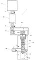
次に、請求項2に記載の発明は、前記請求項1に記載の包装袋供給装置において、前記装着部は、包装袋を保持するための袋保持手段を有すると共に、前記搬送手段は、該袋保持手段が装着位置において包装袋の前部を傾斜姿勢で保持するように設けられていることを特徴とする。
【0012】
この発明によれば、袋保持手段は装着位置において包装袋の前部を傾斜姿勢で保持するから、例えば手動による装着部への包装袋の装着作業が容易となる。
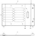
【0013】
そして、例えば底部つまりこの場合後部に折り返しが設けられて多重とされたいわゆるガゼットタイプの包装袋においては、複数積層されると、後部のトータル厚みが前部に比較して大きくなる。その結果、袋保持手段が装着位置において前記包装袋を垂直姿勢で保持する場合には、厚みの肥大化した後部が搬送手段ないし装着部に反発するため、用いる袋保持手段の構成如何では、該袋保持手段による包装袋の前部の保持が危うくなるおそれが生じることがある。一例として、袋保持手段が包装袋の前部に設けられた孔に挿通されるピン状とされている場合、装着された包装袋が前記作用により袋保持手段から脱落する可能性がある。
【0014】
それに対して本発明のように、袋保持手段が包装袋の前部を傾斜姿勢で保持する場合には、包装袋に搬送手段側ないし装着部側への力が作用するため、前記不具合が効果的に回避されるようになり、生産効率が向上する。
【0015】
また、請求項3に記載の発明は、前記請求項2に記載の包装袋供給装置において、前記搬送手段は、装着位置において前記袋保持手段により前部が保持された包装袋の後部が略垂直姿勢で垂下するように設けられていることを特徴とする。
【0016】
この発明によれば、前記請求項2に記載の発明における搬送手段の構成がさらに具体化される。その結果、前述した傾斜姿勢で保持される包装袋の前部と略垂直姿勢で垂下する後部との境界部を支点として、包装袋の後部に搬送手段側ないし装着部側への力が作用することになり、袋保持手段による包装袋の保持が一層確実なものとなる。
【0017】
そして、請求項4に記載の発明は、前記請求項2または請求項3に記載の包装袋供給装置において、前記袋保持手段は、包装袋の前部に設けられた孔が挿入される一対のピン部材で構成され、その間隔が可変とされていることを特徴とする。
【0018】
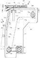
この発明によれば、包装袋側の孔と装着部側のピン部材との係合を介して包装袋を装着する方式であるから、装着作業は容易となる。しかも、装着する包装袋の寸法に応じて前部に設けた一対の孔の間隔が変更されても、該間隔に応じてピン部材の配設間隔を変更することができるから、包装袋の寸法に応じた汎用性のある装置が実現される。
【0019】
また、請求項5に記載の発明は、前記請求項1から請求項4のいずれかに記載の包装袋供給装置において、前記装着部は、前記搬送手段に所定間隔を隔てて複数設けられ、その間隔が、先行の装着部が取出位置にあるときに、後続の装着部が装着位置に位置する間隔とされていることを特徴とする。
【0020】
この発明によれば、例えば先行する装着部が取出位置にあって包装袋が取り出されている間に、装着位置に位置する後続の装着部に包装袋を装着することができるから、従来のように補充のために包装袋の取り出しを停止しなくとも包装袋の補充が可能となり、もって生産効率が一層向上する。
【0021】
また、請求項6に記載の発明は、前記請求項4または請求項5に記載の包装袋供給装置において、前記装着部は、包装袋を裏面側から支持する複数の支持部材を有し、かつ、搬送方向の最前方の支持部材には前記ピン部材が設けられていると共に、最後方の支持部材には包装袋の搬送幅方向の移動を規制する規制部材が設けられていることを特徴とする。
【0022】
この発明によれば、装着部の構成がさらに具体化される。その結果、支持部材、最前方のピン部材、及び最後方の規制部材の設置により、装着部に装着された包装袋が搬送手段において適切に位置決めされると共に該包装袋の搬送中の姿勢が安定し、取出位置における包装袋の取り出しが円滑に行なわれることになる。
【0023】
そして、請求項7に記載の発明は、取出位置で包装袋を1枚ずつ取り出して物品を袋詰めする袋詰装置に関するもので、前記請求項1から請求項6のいずれかに記載の包装袋供給装置が備えられていることを特徴とする。
【0024】
この発明によれば、前記請求項1から請求項6のいずれかに記載の包装袋供給装置で得られた作用と同様の作用が袋詰装置においても得られることになる。
【0025】
【発明の実施の形態】
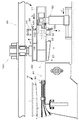
以下、本発明の実施の形態に係る袋詰商品生産ラインについて説明する。
【0026】
図1に示すように、この生産ライン1は、大袋Yの中に複数の小袋X…Xを詰めた袋詰商品Zを生産するもので、該袋詰商品Zには、6個2列に整列した計12個のスナック菓子が充填された小袋X…Xが袋詰めされる。この生産ライン1は主たる構成要素として、包装機10、シールチェッカ20、整列搬送装置30、及び袋詰装置40を含む。
【0027】
包装機10は周知の縦ピロー包装機で、上流側の図示しない計量装置で所定重量に計量されたスナック菓子を小袋Xに充填し、該小袋Xを中継コンベア11上に横姿勢で排出する。排出された小袋Xは、中継コンベア11で搬送されながらシールチェッカ20を通過する間にシール状態の良否が検査される。次いで、シールチェッカ20を通過した小袋Xは、導入コンベア31を経由して整列搬送装置30に1個ずつ順に供給される。整列搬送装置30は、供給された小袋Xを搬送コンベア32に設けた保持部によって縦姿勢としながら、6個1組として袋詰装置40の正面まで搬送する。
【0028】
袋詰装置40の正面に搬送された小袋群X…Xは、整列搬送装置30から袋詰装置40の導入装置41に押し出されたのち、整列装置42で列方向に寄せられて、後続の小袋群X…Xと共に2列に整列される。そして、袋詰位置Lに設置された袋詰ステーション43に、取出位置Mにおいて空の大袋Yが袋供給装置44から取り出されて矢印aで示すように搬送され、ここで該大袋Yの口部が開口されて6個2列に整列した小袋X…Xが矢印bで示すように挿入される。そののち、大袋Yは口部が横シールされ、最終の袋詰商品Zとなって、横シールされた口部を上に向けた縦姿勢状態で排出装置45によって次行程に運び出される。
【0029】
大袋Yは例えば柔軟な合成樹脂製であって、図2に示すように、一方の面にのみ口部Tを超えて延びる延長部Yaが形成されている。また、該延長部Yaに所定間隔を隔てて2つの孔Yb,Ybが設けられている。また、大袋Yには、前記口部Tが形成された端部寄りに、手を通して携行するための長孔Ycが設けられており、該長孔Ycより下の部分つまり図例では左側の部分に小袋X…Xが詰め込まれる。また、大袋Yは、袋詰商品Zとされたとき、前記長孔Ycを挟んだ2箇所S1,S2で横シールされる。このうち左側の横シール箇所S2は、大袋Yの上面と下面とを溶着して詰め込まれた小袋X…Xを密封するものである一方、右側の横シール箇所S1は、同じく大袋Yの上面と下面とを溶着した上で、溶着と同時に前記延長部Yaを大袋Y本体から切断除去するものである。そして、この大袋Yはいわゆるガゼットタイプの包装袋であって、その底部には、袋詰商品Zとされたときに自立可能に厚みを生成するための折り返しYdが形成されており、折り返しYd部分の厚みは大きくなっている。なお、大袋Yは、前記延長部Yaのある面を上にし、かつ、延長部Yaのある側を前部にして袋供給装置44によって搬送されたのち、該袋供給装置44から取り出されて袋詰ステーション43へ供給される。
【0030】
次に、袋詰装置40の主要構成要素のうち特徴的な袋詰ステーション43と袋供給装置44とについて説明する。
【0031】
まず、図3及び図4に示すように、袋詰位置Lに設置された袋詰ステーション43は、取出位置Mにおいて袋供給装置44から1枚ずつ取り出されて供給される大袋Yの口部Tを開口し、該開口を介して整列状態の小袋X…Xを詰め込んだのち、口部T近傍を横シールすることによって袋詰商品Zを得るためのものであり、この袋詰ステーション43には、小袋挿入ガイド51、袋開口装置52、袋縁部把持機構53、下側吸引機構54、横シール機構55、袋延長部押え部材56、及び袋排出フラップ57等が備えられている。
【0032】
小袋挿入ガイド51は筒状で、軸心が水平に延びるように配置されており、図示しないプッシャによって押し出された小袋X…Xはこの小袋挿入ガイド51内を通過して大袋Yに挿入される。
【0033】
袋開口装置52は、床面に配設されたロッド52a,52aに沿って矢印cで示すように前後に移動自在である。該袋開口装置52には、大袋Yの口部Tを開口するように動作する上下左右都合4つの袋開口部材52b…52bが、一対のフレーム部材52c,52c間に架設された一対のロッド(図4には一方のみ示す)52d,52dに沿って矢印dで示すように移動自在に備えられている。
【0034】
袋縁部把持機構53は、大袋Yの比較的前部つまり口部T近傍の左右側縁部を把持する前後左右都合4つのチャック53a…53aを有している。
【0035】
下側吸引機構54は、矢印eで示すように上下動し、下動したときに大袋Yの下面を吸引保持して口部Tを開口する。
【0036】
横シール機構55は、矢印fで示すように上下動する上下一対のシールジョー55a,55bが対接することにより、大袋Yの所定の2箇所S1,S2を横シールする。
【0037】
袋延長部押え部材56は、矢印fで示すように上下動し、下動したときに大袋Yの延長部Yaを上方から押え、前記横シール機構55による横シール時に、該延長部Yaの切り離しを確実とする。
【0038】
そして、袋排出フラップ57は、矢印gで示すように揺動する。すなわち、上方に揺動したときには大袋Yを下方から支持する一方、下方に揺動したときには大袋Yに小袋X…Xが詰め込まれてなる袋詰商品Zを口部Tを上にした姿勢とした上で、下流側の排出装置45に受け渡す。
【0039】
なお、前記袋開口装置52、袋縁部把持機構53、下側吸引機構54、横シール機構55、袋延長部押え部材56、及び袋排出フラップ57等は、それぞれ図示しない駆動源によって駆動される。
【0040】
次に、図5〜図7に示すように装着位置Nと取出位置Mとが設定された袋供給装置44は、装着位置Nで装着された複数の大袋Y…Yを積層状態で取出位置Mへ供給するためのものである。概ね上下方向に延びて側面視略L字状とされた左右一対のサイドフレーム61,61間の前部上方及び後部下方に、シャフト62,63が回転自在に支持されている。該シャフト62,63のサイドフレーム61,61内方の左右両端近傍にはそれぞれスプロケット64,64が組み付けられており、前後に対応するスプロケット64,64間にそれぞれ無端状のチェーン65,65が巻き掛けられている。
【0041】
一方のサイドフレーム61の下方にモータ66が取り付けられており、該モータ66の出力軸に固定されたスプロケット67と、前記サイドフレーム61から外方に突出したシャフト63に組み付けられたスプロケット68との間に無端状のチェーン69が巻き掛けられている。これにより、モータ66の駆動力はチェーン69を介してシャフト63に伝達され、該シャフト63が回転することにより左右のチェーン65,65が走行する。
【0042】
各サイドフレーム61の所定箇所には、チェーン65を案内する所定形状のガイド部材70a〜70gが固設されており、これにより、図例の太い二点鎖線で示すチェーン65は、略上下方向に延びる経路に沿って安定的に循環走行するようになる。すなわち、搬送方向つまり矢印h方向に走行するチェーン65は、取出位置Mで水平方向に走行後、垂直、水平、及び傾斜走行して下方に移動し、そして、上方に垂直走行して装着位置Nを経由したのち、傾斜走行して取出位置Mに至るように配設されている。なお、図5では、図面の複雑化を避けるため、ガイド部材70aのみ記載している。
【0043】
両チェーン65,65間にわたり、かつ、搬送方向hに所定間隔を隔てて、複数の大袋Y…Yが積層状態で装着される4つの装着部80…80が設けられている。その場合の間隔は、先行の装着部80が取出位置Mにあるときに、後続の装着部80が装着位置Nに位置する間隔である。
【0044】
図5に示すように、装着部80は、搬送幅方向に長い概ね断面コ字状の4つの第1〜第4支持部材81〜84を有している。該第1〜第4支持部材81〜84は、両チェーン65,65間にブラケットを介して搬送方向hに所定間隔を隔てて連結されており、大袋Y…Yを裏面側から支持する。
【0045】
図5及び図8に示すように、搬送方向hの最前方の第1支持部材81には、大袋Yの前部に設けられた左右一対の孔Yb,Ybが挿通されるピン部材85,85が立設されており、かつ、両ピン部材85,85間の間隔が可変とされている。
【0046】
すなわち、第1支持部材81と該第1支持部材81に内嵌するように取り付けられた取付部材86とに挟まれて生成された空間部に、左右一対の板状のスライド部材87,87がスライド自在に挿入されている。該スライド部材87,87の内側端部に、前記ピン部材85,85がそれぞれ固設されると共に、外側端部に、前記スライド部材87,87をスライドさせる場合に操作するノブボルト88,88がそれぞれ取り付けられている。また、第1支持部材81の上面には、ピン部材85,85の搬送幅方向の移動を可能にするための長孔81a,81a、及びノブボルト88,88の搬送幅方向の移動を可能にするための長孔81b,81bが設けられている。
【0047】
そして、取付部材86の左右の所定箇所に、それぞれロック部材89,89が固定されている。図9に示すように、該ロック部材89は、ケース89aと、該ケース89aの上部開口から先端部が突出可能なボール89bと、該ボール89bをスライド部材87方向に付勢するスプリング89cとを有している。一方、スライド部材87には、前記ボール89bの先端部が係合可能に4箇所の凹部87a…87aが所定間隔を隔てて形成されている。
【0048】
これにより、ノブボルト88,88を操作してスライド部材87,87をスライドさせ、かつ、ロック部材89,89のボール89b,89bとスライド部材87,87の凹部87a,87aとを係合させることで、両ピン部材85,85を搬送幅方向の予め設定された位置に移動させることができる。この場合、両ピン部材85,85は、実線で示す位置と二点鎖線で示す位置との間で移動可能となり、もって、両ピン部材85,85間の間隔が可変となる。
【0049】
なお、図8に示すように、装着部80に複数の大袋Y…Yを装着する場合の作業性向上のため、ピン部材85,85には、上部に軸方向に長い孔85a,85aが穿設されており、予め複数の大袋Y…Yを孔Yb,Ybを介して保持したワイヤ等でなるコ字状の装着補助部材90の先端部が挿入可能とされている。つまり、装着補助部材90の両先端部を孔85a,85aに挿入後、大袋Y…Yをピン部材85,85側に移動させることにより、装着部80への大袋Y…Yの装着作業は容易となる。
【0050】
そして、第1支持部材81と左右両側のチェーン65,65とは、取付部材86と前述したブラケット91,91とを介して連結されている。
【0051】
また、図5〜図7に示すように、搬送方向hの最後方の第4支持部材84には、大袋Yの搬送幅方向の移動を規制する正面視略L字状とされた左右一対の規制部材92,92が、大袋Yを側方から挟むように立設されている。その場合、説明は省略するが、該規制部材92,92間の間隔は、ノブボルト93,93を操作することにより可変とされている。
【0052】
一方、第1支持部材81と第4支持部材84とで挟まれた第2及び第3支持部材82,83では、搬送幅方向の中央部が所定寸法にわたって上方に折曲されて、該箇所の高さが前記第1及び第4支持部材81,84の高さと同等とされている(例えば、後述する図11も参照)。
【0053】
そして、チェーン65,65は図6及び図7に示す循環経路に沿って走行するため、装着位置Nにおいて、装着部80に備えられたピン部材85,85は若干斜め上方を指向すると共に、該ピン部材85,85は二点鎖線で示す大袋Y…Yの前部を傾斜姿勢で保持する。その場合、大袋Y…Yの後部は略垂直姿勢で垂下することになる。
【0054】
また、チェーン65,65が水平方向に走行する取出位置Mにおいて、装着部80に備えられたピン部材85,85は上方を指向すると共に、該装着部80に装着された大袋Y…Yの前部は第1〜第4支持部材81〜84によって水平姿勢に支持される。その場合、チェーン65,65、装着部80、ないし第1〜第4支持部材81〜84は、大袋Y…Yの後部が張り出し状態となるように構成されている。
【0055】
図10〜図12に示すように、この袋供給装置44には、取出位置Mにおける最上層の大袋Yを水平姿勢に保持する水平保持機構100が備えられている。
【0056】
この水平保持機構100は、取出位置M近傍の両サイドフレーム61,61間に架設された断面コ字状の支持フレーム101上に設けられている。すなわち、該支持フレーム101の上面中央に、電動シリンダ102が設置されている。また、該電動シリンダ102のロッド102aの先端に、搬送幅方向に延びる取付部材103が組み付けられている。また、該電動シリンダ102を挟んで左右両側の支持フレーム101の上面に一対の支持台104,104が固定されており、該支持台104,104に搬送方向hに長いガイドロッド105,105を挿通自在とするガイド部材106,106が固定されている。
【0057】
そして、前記取付部材103は略箱状の支持ケース107に固設されている。また、前記ガイドロッド105,105は、前端部が該支持ケース107に支持されると共に後端部が取付部材103に支持されている。さらに、該支持ケース107の後端部には、搬送幅方向に長いローラ108が回転自在に支持されている。
【0058】
これにより、電動シリンダ102のロッド102aが進退すると、該ロッド102aの先端に組み付けられた取付部材103及び該取付部材103が固設された支持ケース107と一体にローラ108が矢印iで示すように水平方向に移動することになり、該ローラ108は、取付位置Mにおいて張り出し状態とされた大袋Y…Yの後部を、搬送方向hに沿った適宜位置で下方から支持することができる。
【0059】
図5及び図6に示すように、この袋供給装置44には、取出位置Mにおける最上層の大袋Yが水平状態か否かを検出する前後一対の第1及び第2袋位置センサ111,112が備えられている。
【0060】
これらの第1及び第2袋位置センサ111,112は、取出位置Mにおける大袋Y…Yの搬送方向hに対する側部に配設されて、積層状態の大袋Y…Yの側部方向から最上層の大袋Yの前部及び後部の上下方向の位置を検出するためのもので、反射式光電センサが適用されている。両袋位置センサ111,112は、一方のサイドフレーム61にブラケット113を介して固定された電動シリンダ114によって矢印jで示すように昇降自在とされる共通の取付部材115に取り付けられている。
【0061】
図5及び図10に示すように、この袋供給装置44には、取付位置Mにおける大袋Yの有無を検出する第1袋有無センサ121と、図7に示すように、装着位置Nにおける大袋Yの有無を検出する第2袋有無センサ122とが、それぞれ図示しないブラケットを介して所定箇所、つまり、チェーン65,65の走行停止中において、両袋有無センサ121,122と大袋Yとの間に装着部80の第1〜第4支持部材81〜84が位置しない箇所に備えられている。両袋有無センサ121,122には、反射式光電センサが適用されている。なお、第1袋有無センサ121は、支持フレーム101の上方かつ水平保持機構100の支持ケース107の下方に設置されており、該第1袋有無センサ121が大袋Yに臨んでその有無を検出することができるように、前記支持ケース107の上面には、搬送方向hに延びる矩形状の切り欠き107aが形成されている。
【0062】
そして、図3に示すように、袋供給装置44、袋詰ステーション43間には、取出位置Mで袋供給装置44から取り出した空の大袋Yを1枚ずつ袋詰位置Lの袋詰ステーション43に搬送する袋搬送機構130が備えられている。
【0063】
図3及び図4に示すように、この袋搬送機構130は、左右の上部フレーム(図3には一方のみ示す)40a,40a間に架設されたベース131を有する。該ベース131は図示しない駆動源により、矢印kで示すように上部フレーム40a上を前後に移動自在である。ベース131には電動シリンダ132が搭載され、該電動シリンダ132の側部にリニアガイド133,133が固定されると共に、該電動シリンダ132のロッドの先端に水平方向に展開するプレート部材134が取り付けられている。また、プレート部材134に立設されたガイドロッド135,135が前記リニアガイド133,133を挿通しており、プレート部材134は電動シリンダ132の作動により矢印mで示すように上下動自在である。そして、ベース131上面には、第1及び第2真空ポンプ136,137が設けられている。
【0064】
前記プレート部材134下面には複数の吸引部138,139,140が組み付けられている。各吸引部138,139,140は負圧により大袋Yの上面を吸引保持するもので、図13に示すように、最も袋詰ステーション43に近い側の4つの吸引部138a〜138dは大袋Yの口部Tが形成された端部近傍を吸引し、プレート部材134の前後方向の中央部に配置された2つの吸引部139a,139bは大袋Yの左右両側縁部近傍を吸引し、そして、最も袋詰ステーション43から遠い側の2つの吸引部140a,140bは大袋Yの折り返しYdが形成された端部近傍を吸引する。各吸引部138,139,140のうち、吸引部138b,138c,140a,140bは前記第1真空ポンプ136に接続される一方、吸引部138a,138d,139a,139bは前記第2真空ポンプ137に接続される。なお、吸引部138は吸盤形状とされる一方、吸引部139,140は蛇腹形状とされ、図3に示すように、自然状態で、吸引部138は吸引部139,140より高い位置に位置するように構成されている。
【0065】
次に、袋供給装置44の制御システムについて説明すると、図14に示すように、この袋供給装置44を総括的に制御するコントロールユニット150は、各種操作をするための操作部151からの操作信号を入力すると共に、表示部152に各種情報を表示させる。
【0066】
また、コントロールユニット150は、第1及び第2袋位置センサ111,112からの検出信号を入力し、該検出信号に基いてこれら第1及び第2袋位置センサ111,112が取り付けられた取付部材115を昇降させる電動シリンダ114、及び取出位置Mにおいて大袋Y…Yの後部を支持するローラ108を移動させる電動シリンダ102に適宜タイミングで制御信号を出力する。
【0067】
そして、コントロールユニット150は、第1及び第2袋有無センサ121,122からの検出信号を入力し、該検出信号に基いて装着部80…80が設けられたチェーン65,65を循環走行させるモータ66に適宜タイミングで制御信号を出力する。
【0068】
次に、袋詰装置40の特徴と動作例とについて説明する。
【0069】
まず、袋供給装置44の特徴について説明すると、搬送方向hに所定間隔を隔てて4つの装着部80…80が設けられて、積層状態の大袋Y…Yを搬送するチェーン65,65が、図7に示す概ね上下方向に延びる経路に沿って循環走行するように配設されている。そして、上部の水平走行箇所に取出位置Mが設定されると共に、該取出位置Mの斜め下方に装着位置Nが設定されている。
【0070】
すなわち、この袋供給装置44は、装着位置Nから取出位置Mまでの区間が縦型とされているから、従来の水平方向に延びた横型のものに比較して長さあるいは幅等を短縮することが可能となり、コンパクト化及び小型化が図られる。
【0071】
また、装着部80における大袋Y…Yの保持は、大袋Y…Yの前部に設けられた孔Yb,Ybに一対のピン部材85,85を挿入する方式で実現されるから、装着作業は容易となる。しかも、装着する大袋Yの寸法に応じて前部に設けた一対の孔Yb,Ybの間隔が変更されても、該間隔に応じて両ピン部材85,85の配設間隔を変更することができるから、大袋Yの寸法に応じた汎用性のある袋供給装置44が実現される。
【0072】
また、ピン部材85,85は装着位置Nにおいて大袋Y…Yの前部を傾斜姿勢で保持するから、例えば手動による装着部80への大袋Y…Yの装着作業が容易となる。
【0073】
そして、本実施の形態のように、底部つまりこの場合後部に折り返しYdが設けられて多重とされたいわゆるガゼットタイプの大袋Yにおいては、複数積層されると、図7に二点鎖線で模式的に示すように、後部のトータル厚みが前部に比較して大きくなる。その結果、ピン部材85,85が装着位置Nにおいて大袋Y…Yを垂直姿勢で保持する場合には、厚みの肥大化した後部がチェーン65,65ないし装着部80に反発するため、装着された大袋Y…Yが該ピン部材85,85から脱落する可能性がある。それに対して本実施の形態のように、ピン部材85,85が大袋Y…Yの前部を傾斜姿勢で保持する場合には、大袋Y…Yにチェーン65,65側ないし装着部80側への力が作用するため、前記不具合が効果的に回避されるようになり、生産効率が向上する。
【0074】
また、装着位置Nにおいてピン部材85,85により前部が保持された大袋Y…Yの後部が略垂直姿勢で垂下する構成とされているから、前述した傾斜姿勢で保持される大袋Y…Yの前部と略垂直姿勢で垂下する後部との境界部を支点として、大袋Y…Yの後部にチェーン65,65側ないし装着部80側への力が作用することになり、その結果、ピン部材85,85による大袋Y…Yの保持が一層確実なものとなる。
【0075】
また、装着部80は、大袋Y…Yを裏面側から支持する第1〜第4支持部材81〜84を有し、かつ、搬送方向hの最前方の第1支持部材81には前記ピン部材85,85が設けられていると共に、最後方の第4支持部材84には大袋Y…Yの搬送幅方向の移動を規制する規制部材92,92が設けられているから、装着部80に装着された大袋Y…Yが適正に位置決めされると共に該大袋Y…Yの搬送中の姿勢が安定し、取出位置Mにおける大袋Y…Yの取り出しが円滑に行なわれることになる。
【0076】
また、4つの装着部80…80の配設間隔が、先行の装着部80が取出位置Mにあるときに、後続の装着部80が装着位置Nに位置する間隔とされている。そこで、コントロールユニット150が、複数の大袋Y…Yが装着された先行の装着部80が取出位置Mにあるときにチェーン65,65の走行を停止させると、後続の装着部80が装着位置Nに位置することになる。これにより、先行する装着部80が取出位置Mにあって大袋Y…Yが取り出されている間に、装着位置Nに位置する後続の装着部80に大袋Y…Yを装着することができるから、従来のように補充のために袋搬送機構130による大袋Yの取り出しを停止しなくとも大袋Y…Yの補充が可能となり、もって生産効率が一層向上する。
【0077】
チェーン65,65の停止中に、前述した袋供給装置44において、装着位置Nで装着部80に複数の大袋Y…Yが装着されると、該装着部80は上方の取出位置Mへ移動する。
【0078】
次に、袋搬送機構130の動作例について説明すると、図15に示すように、袋供給装置44の上方に位置する袋搬送機構130の吸引部138,139,140が、取出位置Mに停止した袋供給装置44の装着部80に向けて降下し、該装着部80に積み重ねられた最上層の大袋Yの上面に当接したのち該大袋Yを吸引する。その場合、吸引部138,139,140は図13に示す箇所で大袋Yを吸引する。そして、二点鎖線で示すように、当該大袋Yを吸引保持した状態で吸引部138,139,140は上昇する。
【0079】
大袋Yを吸引保持した吸引部138,139,140は、取出位置Mから袋詰位置Lの袋詰ステーション43に向けて水平方向に移動して所定箇所に位置すると、次いで吸引部138,139,140は下降すると同時に、下側吸引部が上昇して、袋搬送行程は終了する。
【0080】
次に、袋詰ステーション43の動作例について説明すると、実線で示すように、吸引部138,139,140は下降すると同時に下側吸引部54が上昇したのち、袋側縁部把持機構53が作動して大袋Yの左右両側縁部を把持すると、次いで吸引部138,139,140は矢印m′で示すように上昇すると同時に下側吸引部54がe′で示すように下降することにより、大袋Yの口部Tを若干開口させる。そして、袋開口装置52が矢印c′で示すように大袋Y方向に前進し、大袋Yの中に4つの袋開口部材52b…52bを挿入させる。このとき、排出フラップ57は上方に揺動する。挿入した袋開口部材52b…52bを大袋Y内を拡張するように作動させる。
【0081】
大袋Y内が所定の大きさに拡張されると、6個2列に幅寄せされて整列された小袋群X…Xが図示しないプッシャによって矢印bで示すように小袋挿入ガイド51内を通過して大袋Y内に挿入される。挿入が完了すると袋開口部材52b…52bは収縮するように作動されると共に、袋開口装置52は後退すると、横シール機構55が作動して大袋Yに横シール部S1,S2を形成する。その後、袋延長部押え部材56が下降して、図13に示すように、横シール時に切断された大袋Yの延長部Yaを上方から押え付ける。袋延長部押え部材56が延長部Yaを押え付けた状態で排出フラップ57が下方に揺動すると、袋詰商品Zが得られ、該袋詰商品Zは口部Tを上にした縦姿勢で排出装置45に受け渡される。
【0082】
このように、袋詰装置40は、前述した特徴を有する袋供給装置44を備えたから、コンパクト化が図られると共に生産効率が向上することになる。
【0083】
ここで、袋供給装置44が有するその他の特徴について説明する。
【0084】
まず、この袋供給装置44では、水平保持機構100によって、取出位置Mの装着部80における最上部の大袋Yは水平姿勢に保持されるから、袋搬送機構130つまり吸引部138,139,140は大袋Yに適正に当接するようになり、大袋Yの該吸引部138,139,140による吸引保持が安定化するため、取り出しミス等がなくなる結果、大袋Yの取り出しが円滑に行われて生産効率が向上する。
【0085】
すなわち、水平保持機構100による大袋Yの水平保持動作について詳しく説明すると、図11に示したように、取出位置Mで装着部80に保持された複数の大袋Y…Yの後部は張り出し状態となっている。そして、該後部が下方から水平保持機構100のローラ108によって水平方向の最適位置で支持されることにより、最上層の大袋Yは水平姿勢に保持される。
【0086】
その場合、大袋Y…Yの側部に、第1及び第2袋位置センサ111,112が、最上層の大袋Yの前部及び後部の上下方向の位置をそれぞれ検出するように備えられている。図例では、最上層の大袋Yは水平姿勢に保持されているから、両袋位置センサ111,112はそれぞれ該大袋Yの前部及び後部を検出する。
【0087】
図16(a)に示すように、装着部80からの大袋Y…Yの取り出しの進行に伴って最上層の大袋Yの上下方向の位置が低くなる。同時に、最上層の大袋Yは水平姿勢に保持されなくなって後部は下方に垂れ下がるため、第1及び第2袋位置センサ111,112はもはや該大袋Yの前部及び後部を検出しなくなる。
【0088】
その場合、コントロールユニット150は、第1及び第2袋位置センサ111,112から入力した検出信号に基いて、以下の制御を実行する。すなわち、第1袋位置センサ111が装着部80で積層状態とされた大袋Yの前部の上面の上下方向の位置を監視し、前述したように、該第1袋位置センサ111が大袋Yの上面を検出しないときには、矢印j′で示すように該第1袋位置センサ111が大袋Yの上面を検出する位置まで下降するように、電動シリンダ114の駆動を制御して該第1袋位置センサ111が取り付けられた取付部材115を下降させる。一方、第2袋位置センサ112は前記取付部材115に取り付けられているから、該第2袋位置センサ112も前記第1袋位置センサ111と同様に下降する。
【0089】
図16(b)に示すように、第1袋位置センサ111が最上層の大袋Yの前部の上面を検出する位置に下降する。その場合、大袋Y…Yの後部は下方に垂れ下がっているから、第2袋位置センサ112は大袋Yの後部の上面より上方に位置することになり、該上面を検出することはできない。
【0090】
すなわち、第1袋位置センサ111が最上層の大袋Yの前部の上面を検出すると共に第2袋位置センサ112が後部の上面を検出しない場合には、コントロールユニット150は、大袋Y…Yの後部を下方から支持するローラ108つまり支持ケース107が矢印i′方向に進出することによって大袋Y…Yの後部を上昇させて、第2袋位置センサ112が最上層の大袋Yの後部の上面を検出するように、水平保持機構100の電動シリンダ102の駆動を制御する。
【0091】
そして、図16(c)に示すように、大袋Y…Yの後部は進出したローラ108によって最適位置で支持されて、第1及び第2袋位置センサ111,112がそれぞれ最上層の大袋Yの前部及び後部の上面を検出するようになり、ひいては最上層の大袋Yは水平姿勢に保持されるようになる。したがって、袋搬送機構130の吸引部138,139,140が該大袋Yに適切に当接するようになり、吸引部138,139,140による大袋Yの吸引保持が安定化するため、取り出しミス等がなくなる結果、大袋Yの取り出しが円滑に行われて生産効率が向上する。特に本実施の形態のように、取出位置Mで大袋Y…Yの後部が張り出し状態となるような場合に、この後部の支持位置の最適化が可能に構成された水平保持機構100は効果的である。
【0092】
そして、この袋供給装置44は、取出位置Mと装着位置Nとに近接して大袋Yの有無を検出する第1及び第2袋有無センサ121,122を備えると共に、これら両袋有無センサ121,122からの検出信号を入力したコントロールユニット150は、該検出信号に基いてチェーン65,65の走行を制御するように構成されている。
【0093】
本実施の形態では、先行の装着部80が取出位置Mにあると共に後続の装着部80が装着位置Nに位置するから、第1袋有無センサ121によって取出位置Mにおいて大袋Yが検出されず、かつ、第2袋有無センサ122によって装着位置Nにおいて大袋Yが検出されたときには、装着位置Nにおいて大袋Y…Yが装着された装着部80を取出位置Mへ移動するように、モータ66の駆動を制御してチェーン65,65を走行させることができるようになる。したがって、取出位置Mへの大袋Y…Yの補充が自動化される。なお、取出位置Mにおいて大袋Yが検出されず、かつ、装着位置Nにおいても大袋Yが検出されないときには、例えば表示部152にエラーメッセージを表示させる等の警告を発し、補充を促すようにすることができる。
【0094】
なお、本実施の形態では、大袋Yは底部に折り返しYdが設けられたいわゆるガゼットタイプのもであったが、折り返しを有さない大袋においても、前述したと同様の作用が得られるのはもちろんである。
【0095】
【発明の効果】
以上説明したように、本発明によれば、生産効率を向上しつつ、包装袋を装着する装着位置から該包装袋を取り出す取出位置までの区間をコンパクト化した包装袋供給装置及びそれを備えた袋詰装置が提供される。すなわち、本発明は、包装袋を取出位置へ供給する包装袋供給装置、及び該包装袋供給装置を備え、取出位置で包装袋を1枚ずつ袋を取り出して物品を袋詰めする袋詰装置に関し、物品包装の技術分野に広く好適である。
【図面の簡単な説明】
【図1】本発明の実施の形態に係る袋詰商品生産ラインの概略平面図である。
【図2】同生産ラインで用いる大袋の構成を示す図であり、(a)は平面図、(b)は側面図である。
【図3】袋詰めステーションの概略側面図である。
【図4】同じく概略背面図である。
【図5】袋供給装置の概略平面図である。
【図6】同じく概略側面図である。
【図7】図5のA−A線による矢視図である。
【図8】図5のB−B線による拡大断面図である。
【図9】ピン部材間の間隔を可変とする構造を説明するための要部拡大図である。
【図10】図6のC−C線による矢視図である。
【図11】図10のD−D線による要部矢視図である。
【図12】図10のE−E線による拡大矢視図である。
【図13】大袋における吸引保持箇所を示す平面図である。
【図14】袋供給装置の制御システムを示すブロック図である。
【図15】袋詰め行程を説明するための図3に相当する概略側面図である。
【図16】水平保持機構の動作を説明するための図11に相当する図であって、(a)は最上層の大袋が水平姿勢に保持されていない状態、(b)は第1及び第2袋位置センサが下降した状態、そして(c)は最上層の大袋が水平姿勢に保持された状態を示す。
【符号の説明】
40 袋詰装置
44 袋供給装置(包装袋供給装置)
65 チェーン(搬送手段)
80 装着部
81〜84 第1〜第4支持部材(支持部材)
85 ピン部材(袋保持手段)
92 規制部材
M 取出位置
N 装着位置
X 小袋(物品)
Y 大袋(包装袋)
Yb 孔[0001]
TECHNICAL FIELD OF THE INVENTION
The present invention relates to a packaging bag supply device that supplies a packaging bag to a takeout position, and a bagging device that includes the packaging bag supply device and takes out the packaging bags one by one at the removal position and packs the articles. Belongs to the technical field.
[0002]
[Prior art]
For example, a product in which a plurality of small bags filled with snacks are arranged and packed in a large bag may be sold. The large bag is made of synthetic resin and is soft and flexible, and is provided with a hole through which a hand can be easily carried after purchase. In general, in such an apparatus for packing articles into packaging bags, a process in which a plurality of packaging bags are mounted on the mounting portion in a stacked state at the mounting position and then supplied to the unloading position, and the packaging bags are removed one by one from the mounting portion at the unloading position. The process of taking out, carrying out the taken out packaging bag to the bagging station at the bagging position, opening the carried packaging bag, inserting the article into the opened packaging bag, and packing the bag is performed.
[0003]
Among them, as a packaging bag supply device for supplying a packaging bag mounted on a mounting portion from a mounting position to an unloading position, for example, there is one described in Patent Literature 1. This apparatus has a conveyor for conveying packaging bags in a horizontal direction. The rear end of the conveyor is a mounting position, and a stocker as a mounting section for holding the packaging bags in a vertical posture and in a stacked state is detachably connected to the rear end. The packaging bag carried out of the stocker by the conveyor is sent forward by a fast-forward conveyor arranged above a substantially intermediate portion of the conveyor, and is gradually brought into a horizontal position. After being supplied to a take-out position provided at the front end of the transport conveyor, each of them is taken up by a suction-type bag take-out mechanism arranged above the take-out position and further conveyed to the downstream side. The replenishment of the packaging bag is performed by replacing the stocker.
[0004]
[Patent Document 1]
Japanese Utility Model Laid-Open Publication No. 5-34107 (page 5, FIG. 1)
[0005]
[Problems to be solved by the invention]
By the way, the packaging bag supply device described in Patent Literature 1 has a configuration in which the packaging bag supply device extends in the horizontal direction from the mounting position to the take-out position. Sometimes.
[0006]
In addition, when refilling the packaging bags, it is necessary to stop taking out the packaging bags and replace them with a stocker holding a plurality of packaging bags in a stacked state each time the previous stocker becomes empty. May cause a decrease. In order to prevent a decrease in efficiency, it is conceivable to prepare a plurality of stockers in advance. In this case, however, it is necessary to secure a place for mounting the stockers in the apparatus, so that the length or width of the apparatus is reduced. In addition, there may be a problem that a stocker having a different size is required for each type of packaging bag.
[0007]
In view of the above situation, the present invention includes a packaging bag supply device and a packaging bag supply device in which a section from a mounting position where a packaging bag is mounted to a take-out position for taking out the packaging bag is reduced while improving production efficiency. It is an object to provide a bag filling device.
[0008]
[Means for Solving the Problems]
In order to solve the above-mentioned problems, the present invention is characterized in that it is configured as follows.
[0009]
First, the invention according to claim 1 relates to a packaging bag supply device for supplying a packaging bag to a take-out position, and transporting the packaging bag from a mounting position where the packaging bag is mounted to the take-out position by circulating and traveling. Means, and a mounting portion provided in the transporting device and to which a packaging bag is mounted, wherein the mounting portion is configured such that the packaging bag is mounted in a substantially vertical posture at the mounting position. It is characterized by.
[0010]
According to the present invention, since the packaging bag is mounted on the mounting portion in a substantially vertical posture, the mounting position can be provided below the removal position. Therefore, since the section from the mounting position to the take-out position can be a vertical conveying means, the length or width can be reduced as compared with the conventional horizontal conveying means extending in the horizontal direction. It is possible to achieve compactness and miniaturization.
[0011]
Next, according to a second aspect of the present invention, in the packaging bag supply device according to the first aspect, the mounting portion has a bag holding unit for holding a packaging bag, and the transporting unit includes The bag holding means is provided so as to hold the front part of the packaging bag in an inclined position at the mounting position.
[0012]
According to this invention, since the bag holding means holds the front part of the packaging bag in the inclined position at the mounting position, for example, the work of manually mounting the packaging bag on the mounting portion becomes easy.
[0013]
And, for example, in a so-called gusset-type packaging bag in which a folded portion is provided at a bottom portion, that is, a rear portion in this case, and a plurality of packaging bags are stacked, the total thickness of the rear portion becomes larger than that of the front portion. As a result, when the bag holding means holds the packaging bag in the vertical position in the mounting position, the rear portion having an enlarged thickness repels the conveying means or the mounting portion. There is a possibility that the holding of the front part of the packaging bag by the bag holding means may be compromised. As an example, when the bag holding means has a pin shape inserted into a hole provided in the front part of the packaging bag, the mounted packaging bag may fall off the bag holding means by the above-described action.
[0014]
On the other hand, when the bag holding means holds the front part of the packaging bag in an inclined position as in the present invention, a force acts on the packaging bag toward the conveying means or the mounting part, so that the above-described disadvantage is effective. And the production efficiency is improved.
[0015]
Further, according to a third aspect of the present invention, in the packaging bag supply device according to the second aspect, the transporting means is arranged such that a rear part of the packaging bag whose front part is held by the bag holding means at a mounting position is substantially vertical. It is provided so as to hang down in a posture.
[0016]
According to this invention, the configuration of the transport means in the invention described in claim 2 is further embodied. As a result, with the fulcrum at the boundary between the front portion of the packaging bag held in the above-described inclined position and the rear portion hanging down in a substantially vertical position, a force acts on the rear portion of the packaging bag toward the transporting means or the mounting portion. As a result, the holding of the packaging bag by the bag holding means becomes more reliable.
[0017]
According to a fourth aspect of the present invention, in the packaging bag supply device according to the second or third aspect, the bag holding means includes a pair of holes into which holes provided in a front portion of the packaging bag are inserted. It is constituted by a pin member, and its interval is variable.
[0018]
According to the present invention, since the packaging bag is mounted via the engagement between the hole on the packaging bag side and the pin member on the mounting portion side, the mounting operation is facilitated. Moreover, even if the interval between the pair of holes provided in the front portion is changed according to the size of the packaging bag to be mounted, the arrangement interval of the pin members can be changed according to the interval. And a versatile device corresponding to the above.
[0019]
According to a fifth aspect of the present invention, in the packaging bag supply device according to any one of the first to fourth aspects, a plurality of the mounting portions are provided at predetermined intervals in the transporting means. The interval is such that when the preceding mounting portion is at the removal position, the subsequent mounting portion is positioned at the mounting position.
[0020]
According to the present invention, for example, while the preceding mounting portion is at the removal position and the packaging bag is being removed, the packaging bag can be mounted on the subsequent mounting portion located at the mounting position. In addition, it is possible to refill the packaging bags without stopping the removal of the packaging bags for replenishment, thereby further improving the production efficiency.
[0021]
According to a sixth aspect of the present invention, in the packaging bag supply device according to the fourth or fifth aspect, the mounting portion has a plurality of support members for supporting the packaging bag from the back side, and The pin member is provided on the foremost support member in the transport direction, and a regulating member for regulating movement of the packaging bag in the transport width direction is provided on the rearmost support member. I do.
[0022]
According to the present invention, the configuration of the mounting portion is further embodied. As a result, by installing the support member, the foremost pin member, and the rearmost regulating member, the packaging bag mounted on the mounting portion is appropriately positioned by the transport means, and the posture of the packaging bag during transportation is stable. However, the packaging bag can be smoothly taken out at the take-out position.
[0023]
The invention according to claim 7 relates to a bagging apparatus for taking out packaging bags one by one at an unloading position and packing the articles into bags, and the packaging bag according to any one of claims 1 to 6. A supply device is provided.
[0024]
According to this invention, the same operation as that obtained by the packaging bag supply device according to any one of claims 1 to 6 can be obtained in the bagging device.
[0025]
BEST MODE FOR CARRYING OUT THE INVENTION
Hereinafter, a bagged product production line according to an embodiment of the present invention will be described.
[0026]
As shown in FIG. 1, the production line 1 is for producing a packaged product Z in which a plurality of small bags X... X are packed in a large bag Y. .. X filled with a total of twelve snacks arranged in a line. The production line 1 includes a packaging machine 10, a seal checker 20, an aligning / conveying device 30, and a bag filling device 40 as main components.
[0027]
The packaging machine 10 is a well-known vertical pillow packaging machine, fills a small bag X with snacks weighed to a predetermined weight by a measuring device (not shown) on the upstream side, and discharges the small bag X onto the relay conveyor 11 in a horizontal posture. The discharged pouches X are inspected for the quality of the sealed state while passing through the seal checker 20 while being conveyed by the relay conveyor 11. Next, the small bags X that have passed through the seal checker 20 are sequentially supplied one by one to the aligning and conveying device 30 via the introduction conveyor 31. The aligning / conveying device 30 conveys the supplied small bags X to the front of the bag filling device 40 as a set of six while keeping the supplied small bags X in a vertical position by the holding unit provided on the conveying conveyor 32.
[0028]
The small bag groups X... X conveyed to the front of the bag filling device 40 are pushed out from the aligning / conveying device 30 to the introduction device 41 of the bag filling device 40, and are then moved in the row direction by the aligning device 42, and the subsequent small bag It is aligned in two rows with groups X... X. Then, the empty large bag Y is taken out of the bag supply device 44 at the take-out position M and is conveyed to the bag filling station 43 installed at the bag filling position L as shown by an arrow a. Are opened and six small bags X... X arranged in two rows are inserted as shown by an arrow b. Thereafter, the large bag Y is horizontally sealed at the mouth to become the final packaged product Z, and is carried out to the next process by the discharge device 45 in the vertical posture with the horizontally sealed mouth facing upward.
[0029]
The large bag Y is made of, for example, a flexible synthetic resin, and has an extended portion Ya extending beyond the mouth T only on one surface as shown in FIG. Further, two holes Yb, Yb are provided in the extension part Ya at a predetermined interval. In addition, the large bag Y is provided with a long hole Yc near the end where the mouth portion T is formed for carrying through a hand, and a portion below the long hole Yc, that is, a left portion in the illustrated example. Are packed with small bags X ... X. Further, when the large bag Y is made into a packaged product Z, the large bag Y is horizontally sealed at two places S1 and S2 with the long hole Yc interposed therebetween. Among them, the left lateral seal portion S2 is for sealing the small bags X... X packed by welding the upper surface and the lower surface of the large bag Y, while the right lateral seal portion S1 is similar to the upper surface of the large bag Y. After welding the lower surface, the extension portion Ya is cut off from the main body of the large bag Y simultaneously with the welding. The large bag Y is a so-called gusset-type packaging bag, and at the bottom thereof, a folded back Yd for forming a thickness so as to be able to stand alone when the bagged product Z is formed is formed. Is thicker. Note that the large bag Y is transported by the bag supply device 44 with the surface with the extension portion Ya facing upward and the side with the extension portion Ya as the front portion, and then taken out of the bag supply device 44 to remove the bag. It is supplied to the filling station 43.
[0030]
Next, the characteristic bag filling station 43 and the bag supply device 44 among the main components of the bag filling device 40 will be described.
[0031]
First, as shown in FIGS. 3 and 4, the bagging station 43 installed at the bagging position L is opened at the unloading position M from the bag supply device 44, and the opening T of the large bag Y supplied and supplied. , X are packed in the aligned state through the opening, and then the bag T is obtained by packing the small bag X by horizontally sealing the vicinity of the mouth T. A small bag insertion guide 51, a bag opening device 52, a bag edge gripping mechanism 53, a lower suction mechanism 54, a horizontal sealing mechanism 55, a bag extension pressing member 56, and a bag discharge flap 57 are provided.
[0032]
The small bag insertion guide 51 is cylindrical and is arranged so that the axis thereof extends horizontally. The small bag X... X pushed out by a pusher (not shown) passes through the small bag insertion guide 51 and is inserted into the large bag Y. .
[0033]
The bag opening device 52 is movable back and forth along the rods 52a, 52a provided on the floor surface as shown by an arrow c. The bag opening device 52 is provided with four bag opening members 52b... 52b that operate so as to open the mouth T of the large bag Y, and a pair of rods ( (Only one is shown in FIG. 4).
[0034]
The bag edge gripping mechanism 53 has four chucks 53a... 53a for front, rear, left and right convenience for gripping a relatively front portion of the large bag Y, that is, right and left edges near the mouth T.
[0035]
The lower suction mechanism 54 moves up and down as shown by the arrow e, and when moved downward, sucks and holds the lower surface of the large bag Y to open the mouth T.
[0036]
The horizontal sealing mechanism 55 horizontally seals two predetermined places S1 and S2 of the large bag Y by a pair of upper and lower seal jaws 55a and 55b moving up and down as shown by an arrow f.
[0037]
The bag extension holding member 56 moves up and down as shown by an arrow f, and when it moves down, presses the extension Ya of the large bag Y from above, and separates the extension Ya during the horizontal sealing by the horizontal sealing mechanism 55. To ensure.
[0038]
Then, the bag discharge flap 57 swings as shown by the arrow g. That is, when swinging upward, the large bag Y is supported from below, and when swinging downward, the bagged product Z, in which the small bags XX are packed in the large bag Y, is set to the posture in which the mouth portion T is directed upward. Above, it is delivered to the discharge device 45 on the downstream side.
[0039]
The bag opening device 52, the bag edge gripping mechanism 53, the lower suction mechanism 54, the horizontal sealing mechanism 55, the bag extension pressing member 56, and the bag discharge flap 57 are each driven by a drive source (not shown). .
[0040]
Next, as shown in FIGS. 5 to 7, the bag supply device 44 in which the mounting position N and the take-out position M are set, the plurality of large bags Y. It is for supplying to. Shafts 62 and 63 are rotatably supported at a front upper portion and a rear lower portion between a pair of left and right side frames 61 extending substantially in the vertical direction and having a substantially L shape in side view. Sprockets 64, 64 are mounted near the left and right ends inside the side frames 61, 61 of the shafts 62, 63, respectively, and endless chains 65, 65 are wound between the sprockets 64, 64 respectively corresponding to the front and rear. It is hung.
[0041]
A motor 66 is mounted below one side frame 61, and a sprocket 67 fixed to an output shaft of the motor 66 and a sprocket 68 mounted on a shaft 63 projecting outward from the side frame 61. An endless chain 69 is wound therebetween. Thus, the driving force of the motor 66 is transmitted to the shaft 63 via the chain 69, and the left and right chains 65, 65 run as the shaft 63 rotates.
[0042]
Guide members 70a to 70g of a predetermined shape for guiding the chain 65 are fixedly provided at predetermined positions of each side frame 61, whereby the chain 65 indicated by a thick two-dot chain line in the example is substantially vertically The vehicle circulates stably along the extending path. That is, the chain 65 traveling in the transport direction, that is, the direction of the arrow h, travels horizontally at the take-out position M, travels vertically, horizontally, and incline to move downward, and travels vertically upward to the mounting position N. After that, it is arranged so as to travel inclining to reach the take-out position M. In FIG. 5, only the guide member 70a is illustrated to avoid complication of the drawing.
[0043]
Four mounting portions 80... 80 on which a plurality of large bags Y... Y are mounted in a stacked state are provided between the two chains 65, 65 and at predetermined intervals in the transport direction h. The interval in that case is an interval at which the succeeding mounting unit 80 is located at the mounting position N when the preceding mounting unit 80 is at the removal position M.
[0044]
As shown in FIG. 5, the mounting section 80 has four first to fourth support members 81 to 84 having a substantially U-shaped cross section that are long in the transport width direction. The first to fourth support members 81 to 84 are connected between the two chains 65, 65 via a bracket at predetermined intervals in the transport direction h, and support the large bags Y ... Y from the back side.
[0045]
As shown in FIGS. 5 and 8, pin members 85, 85 through which a pair of left and right holes Yb, Yb provided in the front part of the large bag Y are inserted, are provided in the first support member 81 at the forefront in the transport direction h. And the distance between the two pin members 85, 85 is variable.
[0046]
That is, a pair of left and right plate-like slide members 87, 87 is provided in a space created between the first support member 81 and the attachment member 86 which is attached to fit inside the first support member 81. It is slidably inserted. The pin members 85, 85 are fixedly provided at inner ends of the slide members 87, 87, and knob bolts 88, 88 which are operated when the slide members 87, 87 are slid, are provided at outer end portions, respectively. Installed. On the upper surface of the first support member 81, long holes 81a, 81a for allowing the pin members 85, 85 to move in the conveying width direction and knob bolts 88, 88 for moving in the conveying width direction are enabled. Long holes 81b, 81b are provided.
[0047]
Lock members 89, 89 are fixed to predetermined positions on the left and right sides of the mounting member 86, respectively. As shown in FIG. 9, the lock member 89 includes a case 89a, a ball 89b whose tip can protrude from an upper opening of the case 89a, and a spring 89c for urging the ball 89b toward the slide member 87. Have. On the other hand, in the slide member 87, four recesses 87a... 87a are formed at predetermined intervals so that the tip of the ball 89b can be engaged.
[0048]
Thereby, the slide members 87, 87 are slid by operating the knob bolts 88, 88, and the balls 89b, 89b of the lock members 89, 89 are engaged with the concave portions 87a, 87a of the slide members 87, 87. The two pin members 85 can be moved to a preset position in the conveying width direction. In this case, the two pin members 85, 85 can be moved between the position shown by the solid line and the position shown by the two-dot chain line, so that the interval between the two pin members 85, 85 becomes variable.
[0049]
As shown in FIG. 8, in order to improve the workability when a plurality of large bags Y... Y are mounted on the mounting portion 80, the pin members 85, 85 are provided with holes 85a, 85a that are long in the axial direction at the top. A tip of a U-shaped mounting assisting member 90 made of a wire or the like that holds a plurality of large bags Y... Y via holes Yb, Yb in advance is insertable. That is, after inserting both ends of the mounting auxiliary member 90 into the holes 85a, 85a, the large bags Y,..., Y are moved toward the pin members 85, 85, so that the mounting operation of the large bags Y,. It becomes.
[0050]
The first support member 81 and the left and right chains 65, 65 are connected via the mounting member 86 and the brackets 91, 91 described above.
[0051]
Further, as shown in FIGS. 5 to 7, a pair of right and left left and right L-shaped front-view restricting movements of the large bag Y in the conveyance width direction is provided on the fourth support member 84 at the rearmost position in the conveyance direction h. The regulating members 92, 92 are erected so as to sandwich the large bag Y from the side. In this case, although the description is omitted, the interval between the regulating members 92, 92 is made variable by operating the knob bolts 93, 93.
[0052]
On the other hand, in the second and third support members 82 and 83 sandwiched between the first support member 81 and the fourth support member 84, the central portions in the transport width direction are bent upward over a predetermined dimension, and The height is equal to the height of the first and fourth support members 81 and 84 (for example, see also FIG. 11 described later).
[0053]
Since the chains 65, 65 travel along the circulation path shown in FIGS. 6 and 7, at the mounting position N, the pin members 85, 85 provided on the mounting portion 80 are directed slightly obliquely upward, and The pin members 85, 85 hold the front portions of the large bags Y,... In that case, the rear part of the large bags Y ... Y will hang down in a substantially vertical posture.
[0054]
Further, at the take-out position M where the chains 65, 65 travel in the horizontal direction, the pin members 85, 85 provided on the mounting portion 80 are directed upward and in front of the large bags Y,. The portion is supported in a horizontal posture by first to fourth support members 81 to 84. In this case, the chains 65, 65, the mounting portion 80, and the first to fourth support members 81 to 84 are configured such that the rear portions of the large bags Y.
[0055]
As shown in FIGS. 10 to 12, the bag supply device 44 includes a horizontal holding mechanism 100 that holds the uppermost large bag Y at the take-out position M in a horizontal posture.
[0056]
The horizontal holding mechanism 100 is provided on a support frame 101 having a U-shaped cross section which is provided between the side frames 61 near the take-out position M. That is, the electric cylinder 102 is installed at the center of the upper surface of the support frame 101. Further, a mounting member 103 extending in the transport width direction is attached to a tip of a rod 102a of the electric cylinder 102. Further, a pair of support bases 104, 104 are fixed on the upper surfaces of the left and right support frames 101 with the electric cylinder 102 interposed therebetween, and guide rods 105, 105 long in the transport direction h are inserted through the support bases 104, 104. Flexible guide members 106, 106 are fixed.
[0057]
The mounting member 103 is fixed to a substantially box-shaped support case 107. The guide rods 105 have a front end supported by the support case 107 and a rear end supported by the mounting member 103. Further, at the rear end of the support case 107, a roller 108 long in the transport width direction is rotatably supported.
[0058]
As a result, when the rod 102a of the electric cylinder 102 advances and retreats, the roller 108 is integrated with the mounting member 103 attached to the tip of the rod 102a and the support case 107 to which the mounting member 103 is fixed as shown by an arrow i. The roller 108 moves in the horizontal direction, so that the roller 108 can support the rear portion of the large bags Y,..., Y in the extended state at the attachment position M, from below at an appropriate position along the transport direction h.
[0059]
As shown in FIGS. 5 and 6, the bag supply device 44 includes a pair of first and second bag position sensors 111 and 112 for detecting whether or not the uppermost large bag Y at the take-out position M is in a horizontal state. Is provided.
[0060]
These first and second bag position sensors 111 and 112 are disposed on the side of the large bags Y... Y in the take-out position M with respect to the transport direction h, and are arranged on the uppermost layer from the side of the stacked large bags Y. And a reflection type photoelectric sensor is used to detect the vertical position of the front part and the rear part of the large bag Y. Both bag position sensors 111 and 112 are mounted on a common mounting member 115 which can be moved up and down as shown by an arrow j by an electric cylinder 114 fixed to one side frame 61 via a bracket 113.
[0061]
As shown in FIGS. 5 and 10, the bag supply device 44 includes a first bag presence / absence sensor 121 for detecting the presence / absence of the large bag Y at the mounting position M, and a large bag Y at the mounting position N as shown in FIG. A second bag presence / absence sensor 122 for detecting the presence / absence of a bag is provided at a predetermined location via a bracket (not shown), that is, between the two bag presence / absence sensors 121 and 122 and the large bag Y while the running of the chains 65 and 65 is stopped. It is provided at a position where the first to fourth support members 81 to 84 of the mounting portion 80 are not located. A reflection-type photoelectric sensor is applied to both the bag presence / absence sensors 121 and 122. The first bag presence / absence sensor 121 is installed above the support frame 101 and below the support case 107 of the horizontal holding mechanism 100, and the first bag presence / absence sensor 121 faces the large bag Y and detects the presence or absence thereof. The support case 107 has a rectangular cutout 107a extending in the transport direction h on the upper surface thereof.
[0062]
Then, as shown in FIG. 3, between the bag supplying device 44 and the bag filling station 43, the empty large bags Y taken out of the bag supplying device 44 at the unloading position M are placed one by one at the bag filling station 43 at the bag filling position L. Is provided with a bag transport mechanism 130 for transporting the bag.
[0063]
As shown in FIGS. 3 and 4, the bag transport mechanism 130 has a base 131 provided between left and right upper frames (only one is shown in FIG. 3) 40a. The base 131 can be moved back and forth on the upper frame 40a by a driving source (not shown) as shown by an arrow k. An electric cylinder 132 is mounted on the base 131, and linear guides 133 and 133 are fixed to side portions of the electric cylinder 132, and a plate member 134 that expands horizontally is attached to a tip of a rod of the electric cylinder 132. ing. Further, guide rods 135 and 135 erected on the plate member 134 pass through the linear guides 133 and 133, and the plate member 134 can be moved up and down by the operation of the electric cylinder 132 as shown by an arrow m. The first and second vacuum pumps 136 and 137 are provided on the upper surface of the base 131.
[0064]
A plurality of suction portions 138, 139, 140 are attached to the lower surface of the plate member 134. Each of the suction units 138, 139, and 140 sucks and holds the upper surface of the large bag Y by negative pressure, and the four suction units 138a to 138d closest to the bagging station 43 are provided with the large bag Y as shown in FIG. The suction portion 139a, 139b disposed at the center in the front-rear direction of the plate member 134 sucks the vicinity of the end where the mouth portion T is formed, and suctions the vicinity of the left and right side edges of the large bag Y. The two suction units 140a and 140b farther from the bagging station 43 suction the vicinity of the end of the large bag Y where the folded back Yd is formed. Of the suction units 138, 139, 140, the suction units 138b, 138c, 140a, 140b are connected to the first vacuum pump 136, while the suction units 138a, 138d, 139a, 139b are connected to the second vacuum pump 137. Connected. The suction section 138 has a suction cup shape, while the suction sections 139 and 140 have a bellows shape. As shown in FIG. 3, in a natural state, the suction section 138 is located at a position higher than the suction sections 139 and 140. It is configured as follows.
[0065]
Next, a control system of the bag supply device 44 will be described. As shown in FIG. 14, a control unit 150 for generally controlling the bag supply device 44 receives an operation signal from an operation unit 151 for performing various operations. Is input, and various information is displayed on the display unit 152.
[0066]
Further, the control unit 150 receives detection signals from the first and second bag position sensors 111 and 112 and, based on the detection signals, an attachment member to which the first and second bag position sensors 111 and 112 are attached. Control signals are output to the electric cylinder 114 for raising and lowering the 115 and the electric cylinder 102 for moving the roller 108 supporting the rear part of the large bags Y...
[0067]
The control unit 150 receives detection signals from the first and second bag presence / absence sensors 121 and 122, and based on the detection signals, circulates the chains 65 and 65 provided with the mounting portions 80. A control signal is output to the control unit 66 at appropriate timing.
[0068]
Next, features and an operation example of the bag filling device 40 will be described.
[0069]
First, the characteristics of the bag supply device 44 will be described. Chains 65, 65 provided with four mounting portions 80... 80 at predetermined intervals in the transport direction h and transporting the large bags Y. 7 so as to circulate along a path extending substantially vertically. The take-out position M is set at the upper horizontal travel position, and the mounting position N is set diagonally below the take-out position M.
[0070]
That is, since the section from the mounting position N to the take-out position M is vertical, the length or width of the bag supply device 44 is shorter than that of the conventional horizontal type extending horizontally. It is possible to achieve compactness and miniaturization.
[0071]
Further, the holding of the large bags Y... Y in the mounting portion 80 is realized by a method of inserting a pair of pin members 85 and 85 into holes Yb and Yb provided in the front portion of the large bags Y. It will be easier. Moreover, even if the interval between the pair of holes Yb, Yb provided in the front portion is changed according to the size of the large bag Y to be mounted, the arrangement interval between the two pin members 85, 85 can be changed according to the interval. Therefore, a versatile bag supply device 44 corresponding to the size of the large bag Y is realized.
[0072]
Further, since the pin members 85, 85 hold the front portions of the large bags Y... Y in the inclined position at the mounting position N, for example, the work of mounting the large bags Y.
[0073]
Then, as in the present embodiment, in a so-called gusset-type large bag Y which is provided with a folded back Yd at the bottom, that is, at the rear in this case, and is multiplexed, a plurality of stacked bags Y are schematically indicated by two-dot chain lines in FIG. As shown in (2), the total thickness of the rear part is larger than that of the front part. As a result, when the pin members 85, 85 hold the large bags Y,... Y in the vertical position at the mounting position N, the enlarged rear portion rebounds from the chains 65, 65 or the mounting portion 80, so that the mounting is performed. There is a possibility that the large bags Y ... Y fall off the pin members 85,85. On the other hand, when the pin members 85, 85 hold the front portions of the large bags Y,... Y in an inclined posture as in the present embodiment, the large bags Y,. Since the above-mentioned force acts, the above-mentioned problem can be effectively avoided, and the production efficiency is improved.
[0074]
Further, since the rear portion of the large bags Y... Y whose front portions are held by the pin members 85 at the mounting position N hang down in a substantially vertical posture, the large bags Y. A force acting on the chain 65, 65 side or the mounting portion 80 side acts on the rear portion of the large bag Y... Y with the boundary between the front portion of the main bag and the rear portion hanging down in a substantially vertical position as a fulcrum. The holding of the large bags Y... Y by the members 85, 85 becomes more reliable.
[0075]
Further, the mounting portion 80 has first to fourth support members 81 to 84 for supporting the large bags Y... Y from the back side, and the first support member 81 at the forefront in the transport direction h has the pin member. 85, and the rearmost fourth support member 84 is provided with regulating members 92, 92 for regulating the movement of the large bags Y... Y in the conveying width direction. The large bags Y... Y are properly positioned, and the posture of the large bags Y... Y during transportation is stabilized, so that the large bags Y.
[0076]
The spacing between the four mounting portions 80... 80 is such that when the preceding mounting portion 80 is at the removal position M, the subsequent mounting portion 80 is at the mounting position N. Then, when the control unit 150 stops the traveling of the chains 65, 65 when the preceding mounting portion 80 on which the plurality of large bags Y... Y are mounted is at the take-out position M, the subsequent mounting portion 80 moves to the mounting position N. Will be located. This allows the large bags Y... Y to be mounted on the subsequent mounting portion 80 located at the mounting position N while the preceding mounting section 80 is at the removal position M and the large bags Y. In addition, the large bags Y ... Y can be replenished without stopping the removal of the large bags Y by the bag transport mechanism 130 for replenishment as in the related art, thereby further improving the production efficiency.
[0077]
When a plurality of large bags Y... Y are mounted on the mounting portion 80 at the mounting position N in the above-described bag supply device 44 while the chains 65, 65 are stopped, the mounting portion 80 moves to the upper unloading position M. .
[0078]
Next, an operation example of the bag transport mechanism 130 will be described. As shown in FIG. 15, the suction units 138, 139, and 140 of the bag transport mechanism 130 located above the bag supply device 44 have stopped at the unloading position M. After descending toward the mounting portion 80 of the bag supply device 44 and contacting the upper surface of the uppermost large bag Y stacked on the mounting portion 80, the large bag Y is sucked. In this case, the suction units 138, 139, and 140 suction the large bag Y at the location shown in FIG. Then, as indicated by the two-dot chain line, the suction units 138, 139, and 140 move upward while the large bag Y is held by suction.
[0079]
The suction units 138, 139, and 140 holding the large bag Y by suction move horizontally from the unloading position M to the bagging station 43 at the bagging position L and are located at predetermined positions. At the same time as 140 is lowered, the lower suction section is raised, and the bag conveying process is completed.
[0080]
Next, an operation example of the bagging station 43 will be described. As shown by a solid line, after the suction units 138, 139 and 140 are lowered and the lower suction unit 54 is raised, the bag side edge gripping mechanism 53 is operated. Then, when the left and right side edges of the large bag Y are gripped, the suction portions 138, 139, and 140 rise as shown by the arrow m ', and simultaneously, the lower suction portion 54 descends as shown by the arrow e'. The mouth T of Y is slightly opened. Then, the bag opening device 52 advances in the large bag Y direction as shown by the arrow c ', and the four bag opening members 52b ... 52b are inserted into the large bag Y. At this time, the discharge flap 57 swings upward. The inserted bag opening members 52b... 52b are operated to expand the inside of the large bag Y.
[0081]
When the inside of the large bag Y is expanded to a predetermined size, a group of small bags X... X aligned in a row of six rows and two rows passes through the small bag insertion guide 51 as shown by an arrow b by a pusher (not shown). Inserted into the large bag Y. When the insertion is completed, the bag opening members 52b... 52b are operated to contract, and when the bag opening device 52 is retracted, the horizontal sealing mechanism 55 is operated to form horizontal sealing portions S1 and S2 in the large bag Y. Thereafter, the bag extension pressing member 56 is lowered to press the extended portion Ya of the large bag Y cut at the time of the horizontal sealing from above as shown in FIG. When the discharge flap 57 swings downward with the bag extension holding member 56 holding down the extension Ya, a bagged product Z is obtained, and the bagged product Z is in a vertical position with the mouth T up. It is delivered to the discharge device 45.
[0082]
As described above, since the bag filling device 40 includes the bag supply device 44 having the above-described features, the size is reduced and the production efficiency is improved.
[0083]
Here, other features of the bag supply device 44 will be described.
[0084]
First, in the bag supply device 44, the uppermost large bag Y in the mounting portion 80 at the take-out position M is held in the horizontal posture by the horizontal holding mechanism 100, so that the bag transport mechanism 130, that is, the suction units 138, 139, and 140, Since the large bag Y comes into proper contact with the large bag Y and the suction holding of the large bag Y by the suction portions 138, 139, and 140 is stabilized, there is no mistake in taking out the large bag Y. As a result, the large bag Y is smoothly taken out and the production efficiency is improved. Is improved.
[0085]
That is, the horizontal holding operation of the large bag Y by the horizontal holding mechanism 100 will be described in detail. As shown in FIG. 11, the rear portions of the plurality of large bags Y... ing. The rear portion is supported from below by the rollers 108 of the horizontal holding mechanism 100 at an optimal position in the horizontal direction, so that the uppermost large bag Y is held in a horizontal posture.
[0086]
In this case, the first and second bag position sensors 111 and 112 are provided on the sides of the large bags Y... Y so as to detect the front and rear positions of the front and rear portions of the uppermost large bag Y, respectively. . In the illustrated example, since the uppermost large bag Y is held in a horizontal posture, both bag position sensors 111 and 112 detect the front portion and the rear portion of the large bag Y, respectively.
[0087]
As shown in FIG. 16A, as the large bags Y... Y are taken out from the mounting portion 80, the vertical position of the uppermost large bag Y decreases. At the same time, the uppermost large bag Y is no longer held in the horizontal position and the rear portion hangs down, so that the first and second bag position sensors 111 and 112 no longer detect the front and rear portions of the large bag Y.
[0088]
In that case, the control unit 150 executes the following control based on the detection signals input from the first and second bag position sensors 111 and 112. That is, the first bag position sensor 111 monitors the vertical position of the upper surface of the front part of the large bag Y stacked in the mounting unit 80, and as described above, the first bag position sensor 111 When the upper surface is not detected, the driving of the electric cylinder 114 is controlled so that the first bag position sensor 111 moves down to a position where the first bag position sensor 111 detects the upper surface of the large bag Y as indicated by an arrow j '. The attachment member 115 to which the attachment 111 is attached is lowered. On the other hand, since the second bag position sensor 112 is attached to the mounting member 115, the second bag position sensor 112 also descends similarly to the first bag position sensor 111.
[0089]
As shown in FIG. 16B, the first bag position sensor 111 moves down to a position where the first bag position sensor 111 detects the upper surface of the front portion of the uppermost large bag Y. In this case, the rear portion of the large bags Y... Y hangs downward, so that the second bag position sensor 112 is located above the upper surface of the rear portion of the large bag Y, and cannot detect the upper surface.
[0090]
That is, when the first bag position sensor 111 detects the upper surface of the front portion of the uppermost large bag Y and the second bag position sensor 112 does not detect the upper surface of the rear portion, the control unit 150 determines whether the large bags Y. The roller 108 supporting the rear portion from below, that is, the support case 107 advances in the direction of the arrow i 'to raise the rear portion of the large bag Y... Y, and the second bag position sensor 112 moves the upper surface of the rear portion of the uppermost large bag Y. The drive of the electric cylinder 102 of the horizontal holding mechanism 100 is controlled so as to be detected.
[0091]
Then, as shown in FIG. 16 (c), the rear portion of the large bags Y... Y is supported at the optimum position by the advanced roller 108, and the first and second bag position sensors 111 and 112 are respectively connected to the uppermost large bag Y. The upper surface of the front part and the upper part of the rear part are detected, so that the uppermost large bag Y is held in a horizontal posture. Therefore, the suction sections 138, 139, and 140 of the bag transport mechanism 130 appropriately come into contact with the large bag Y, and the suction section 138, 139, and 140 stabilize the suction of the large bag Y. As a result, the large bag Y is taken out smoothly and the production efficiency is improved. Particularly, as in the present embodiment, when the rear portion of the large bag Y... Y becomes protruding at the take-out position M, the horizontal holding mechanism 100 configured to optimize the support position of the rear portion is effective. It is.
[0092]
The bag supply device 44 includes first and second bag presence / absence sensors 121 and 122 for detecting the presence / absence of the large bag Y in the vicinity of the unloading position M and the attachment position N, and the two bag presence / absence sensors 121 and 122. The control unit 150 to which the detection signal is input from the control unit 122 is configured to control the running of the chains 65 based on the detection signal.
[0093]
In the present embodiment, since the preceding mounting portion 80 is at the removal position M and the subsequent mounting portion 80 is at the mounting position N, the large bag Y is not detected at the removal position M by the first bag presence / absence sensor 121, When the large bag Y is detected at the mounting position N by the second bag presence / absence sensor 122, the motor 66 is driven so that the mounting portion 80 with the large bags Y. Can be controlled to drive the chains 65, 65. Therefore, the replenishment of the large bags Y... Y to the unloading position M is automated. If the large bag Y is not detected at the unloading position M and the large bag Y is not detected at the mounting position N, a warning such as displaying an error message on the display unit 152 is issued to urge replenishment. Can be.
[0094]
In the present embodiment, the large bag Y is a so-called gusset type in which the folded portion Yd is provided at the bottom portion. However, the same effect as described above can be obtained with a large bag having no folded portion. It is.
[0095]
【The invention's effect】
As described above, according to the present invention, a packaging bag supply device having a compact section from a mounting position where a packaging bag is mounted to a take-out position where the packaging bag is taken out and a packaging bag supply device are provided, while improving production efficiency. A bagging device is provided. That is, the present invention relates to a packaging bag supply device that supplies a packaging bag to a take-out position, and a bag filling device that includes the packaging bag supply device and takes out the bags one by one at the take-out position and packs articles. Widely suitable for the technical field of article packaging.
[Brief description of the drawings]
FIG. 1 is a schematic plan view of a bagged product production line according to an embodiment of the present invention.
FIG. 2 is a diagram showing a configuration of a large bag used in the production line, wherein (a) is a plan view and (b) is a side view.
FIG. 3 is a schematic side view of a bag filling station.
FIG. 4 is also a schematic rear view.
FIG. 5 is a schematic plan view of the bag supply device.
FIG. 6 is a schematic side view of the same.
FIG. 7 is a view as viewed in the direction of arrows AA in FIG. 5;
FIG. 8 is an enlarged sectional view taken along line BB of FIG. 5;
FIG. 9 is an enlarged view of a main part for describing a structure in which a distance between pin members is variable.
FIG. 10 is a view taken along line CC in FIG. 6;
FIG. 11 is a main part arrow view taken along line DD in FIG. 10;
FIG. 12 is an enlarged view taken on line EE of FIG. 10;
FIG. 13 is a plan view showing a suction holding portion in the large bag.
FIG. 14 is a block diagram showing a control system of the bag supply device.
FIG. 15 is a schematic side view corresponding to FIG. 3 for explaining a bag filling process.
FIG. 16 is a view corresponding to FIG. 11 for explaining the operation of the horizontal holding mechanism, wherein (a) shows a state in which the uppermost large bag is not held in a horizontal posture, and (b) shows first and second bags. (C) shows a state in which the two bag position sensor is lowered, and (c) shows a state in which the uppermost large bag is held in a horizontal posture.
[Explanation of symbols]
40 bagging equipment
44 Bag supply device (packaging bag supply device)
65 chain (transportation means)
80 Mounting part
81 to 84 First to fourth support members (support members)
85 pin member (bag holding means)
92 Regulation members
M Removal position
N Mounting position
X small bag (article)
Y Large bag (packaging bag)
Yb hole