JP2004335437A - Electrical connector - Google Patents
Electrical connector Download PDFInfo
- Publication number
- JP2004335437A JP2004335437A JP2003313272A JP2003313272A JP2004335437A JP 2004335437 A JP2004335437 A JP 2004335437A JP 2003313272 A JP2003313272 A JP 2003313272A JP 2003313272 A JP2003313272 A JP 2003313272A JP 2004335437 A JP2004335437 A JP 2004335437A
- Authority
- JP
- Japan
- Prior art keywords
- electrical connector
- operating
- circuit board
- base
- connector according
- Prior art date
- Legal status (The legal status is an assumption and is not a legal conclusion. Google has not performed a legal analysis and makes no representation as to the accuracy of the status listed.)
- Pending
Links
Images
Classifications
-
- H—ELECTRICITY
- H05—ELECTRIC TECHNIQUES NOT OTHERWISE PROVIDED FOR
- H05K—PRINTED CIRCUITS; CASINGS OR CONSTRUCTIONAL DETAILS OF ELECTRIC APPARATUS; MANUFACTURE OF ASSEMBLAGES OF ELECTRICAL COMPONENTS
- H05K7/00—Constructional details common to different types of electric apparatus
- H05K7/02—Arrangements of circuit components or wiring on supporting structure
- H05K7/10—Plug-in assemblages of components, e.g. IC sockets
- H05K7/1053—Plug-in assemblages of components, e.g. IC sockets having interior leads
Landscapes
- Engineering & Computer Science (AREA)
- Microelectronics & Electronic Packaging (AREA)
- Details Of Connecting Devices For Male And Female Coupling (AREA)
- Connecting Device With Holders (AREA)
- Coupling Device And Connection With Printed Circuit (AREA)
Abstract
【課題】 本発明は、一種の割に大きい且つ操作に便利な稼動アームの操作空間を有する電気コネクタを提供することを目的とする。
【解決手段】 本発明の電気コネクタは、チップモジュールと回路基板とを電気的に接続することに用いられ、回路基板に取付けられるベースと、ベースの一端に可動的に枢設蓋体と、前記の蓋体をベースに押さえる稼動アームと、を備える。前記稼動アームは、接続部と、接続部の末端が曲げることによって形成する曲がり部と、曲がり部の末端から伸びる操作部とを含み、前記稼動部が押圧部を動かすために水平位置と垂直位置の間で回転でき、前記蓋体に押圧部と結合する鉤が設けられる。その中、曲がり部と操作部の平面が接続部と枢設部の平面に対して傾斜して伸び、電気コネクタの閉じる時、操作部と回路基板の距離を接続部と回路基板より大きくさせる。
【選択図】 図2PROBLEM TO BE SOLVED: To provide an electric connector having an operation space of an operation arm which is large in kind and convenient for operation.
An electric connector according to the present invention is used for electrically connecting a chip module and a circuit board, and includes a base attached to the circuit board, a pivotally movable lid at one end of the base, And an operating arm that presses the lid on the base. The operating arm includes a connecting portion, a bent portion formed by bending the end of the connecting portion, and an operating portion extending from the end of the bent portion, and the operating portion moves the pressing portion in a horizontal position and a vertical position. The cover is provided with a hook which can be rotated between the pushers. In this case, the planes of the bent portion and the operation portion extend obliquely with respect to the planes of the connection portion and the pivot portion, and when the electric connector is closed, the distance between the operation portion and the circuit board is made larger than that of the connection portion and the circuit board.
[Selection] Figure 2
Description
本発明は、一種の電気コネクタに関し、特にLGAチップモジュールと回路基板とを電気的に接続するために用いられ、且つ、より良好な操作性能を持っている電気コネクタに関するものである。 The present invention relates to an electrical connector, and more particularly, to an electrical connector that is used to electrically connect an LGA chip module to a circuit board and has better operability.
LGAコネクタはLGAチップモジュールと回路基板とを電気的に接続することに通常に使われ、且つ、該電気コネクタとチップモジュールとの間に押え方式で二者の導電部材の接触を達成し、且つ、二者の安定的電気的な接続を達成する。相関する技術は非特許文献1を参照する。
The LGA connector is commonly used to electrically connect the LGA chip module and the circuit board, and achieves contact between the two conductive members in a pressing manner between the electric connector and the chip module; and To achieve a stable electrical connection between the two. For the related technique, refer to Non-Patent
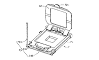
図1を参照すると、従来のLGA電気コネクタ7はベース71と、該ベース71の外囲に設置される筐体72と、ベース71に回転可能に枢設される蓋体72と、蓋体72をベース71に押される稼動アーム73とを備える。前記稼動アーム73に枢設部731と押圧部732及び稼動部733を含める。前記稼動部733は押圧部732を動かすために水平の位置と垂直の位置の間に回転され、蓋体72に押圧部732と結合する鉤721が設けられる。LGAチップモジュールは電気コネクタ7に取り付けられた後、蓋体72を閉じ、且つ、稼動部733を動かし、押圧部732を蓋体72の鉤721に押させ、LGAチップモジュールと電気コネクタ7の間の固着力を保証し、そこで、両者の間でしっかりと電気的に接続することを保証することになる。相関する技術は特許文献2を参照する。
Referring to FIG. 1, the conventional LGA electrical connector 7 includes a
しかし、電気コネクタ7が閉じている時、稼動アーム73の稼動部733が水平の位置にあって、それと回路基板の間の距離はとても小さい、そこで、操作者が手で稼動部733を起こす時、操作の空間が小さいので、操作者の指が回路基板あるいは他の電気素子に容易に触れられるので、操作に不便である。前記の欠点を克服するために一種の新式の電気コネクタを設計するのは必要である。
本発明は一種のイジェクト機構のカムレバー自由端の運動に制限されて、かつ構成が簡単な記憶カードコネクタを提供することを目的とする。 SUMMARY OF THE INVENTION It is an object of the present invention to provide a storage card connector which is limited to the movement of a cam lever free end of a kind of eject mechanism and has a simple structure.
本発明の電気コネクタはチップモジュールと回路基板とを電気的に接続することに用いられ、回路基板に取付けられるベースと、ベースの一端に可動的に枢設蓋体と、前記の蓋体をベースに押さえる稼動アームと、を備える。前記稼動アームに接続部と、接続部の末端が曲がることによって形成する曲がり部と、曲がり部の末端から伸びる操作部とを含め、前記稼動部が押圧部を動かすために水平位置と垂直位置の間で回転でき、前記蓋体に押圧部と結合する鉤が設けられる。LGAチップモジュールが電気コネクタに取り付けられる時、蓋体を閉じ且つ稼動部を動かし、押圧部を蓋体の鉤に押さえ、LGAチップモジュールと電気コネクタの間の固着力を確保し、そこで、両者の穏定的に電気的に接続することを確保する。その中、曲がり部と操作部の平面が接続部と枢設部の平面に対して傾斜して伸び、電気コネクタの閉じる時、操作部と回路基板の距離を接続部と回路基板より大きくさせる。 The electric connector of the present invention is used to electrically connect a chip module to a circuit board, and includes a base attached to the circuit board, a pivotally movable lid at one end of the base, and the lid as a base. And an operating arm for pressing the arm. The operating arm includes a connection portion, a bent portion formed by bending the end of the connection portion, and an operation portion extending from the end of the bent portion, and includes a horizontal position and a vertical position for the operating portion to move the pressing portion. The lid is provided with a hook which can rotate between the hooks and is connected to the pressing portion. When the LGA chip module is attached to the electrical connector, the lid is closed and the operating part is moved, the pressing part is pressed by the hook of the lid, and the fixing force between the LGA chip module and the electrical connector is secured. Ensure a gentle electrical connection. In this case, the planes of the bent portion and the operation portion extend obliquely with respect to the planes of the connection portion and the pivot portion, and when the electric connector is closed, the distance between the operation portion and the circuit board is made larger than that of the connection portion and the circuit board.
従来の技術と比べて、本発明の利点に電気コネクタが閉じる時、操作部と回路基板の距離が接続部と回路基板より大きくされ、そこで、稼動部の操作空間を増し、操作に便利である。 Compared with the prior art, the advantage of the present invention is that when the electrical connector is closed, the distance between the operation part and the circuit board is made larger than the connection part and the circuit board, so that the operation space of the operation part is increased and the operation is convenient. .
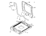
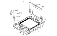
図2と図3を参照すると、本発明の電気コネクタ1は表面押さえの形式でLGAチップモジュール5と回路基板6を電気的に接続し、ベース2とベースに可動的に設けられる蓋体3及び稼動アーム4と、を備える。
Referring to FIGS. 2 and 3, the
ベース2にLGAチップモジュール5を受ける受け部23が設けられ、前記受け部23の一端に蓋3を枢設する第一枢設部21が設けられ、ベース2と前記第一枢設部21のもう一端に稼動アーム4と枢設する第二枢設部22が設けられ、且つ、第一枢設端21と第二枢設端22を垂直に接続する側面に鉤24が設けられる。
A receiving
蓋体3は内部に開口を有する矩形の構成であって、ベース2の第一枢設端21に枢設される枢設端31と、枢設端31と対向する一端に位置し且つ外側へ伸びる鉤32と、LGAチップモジュール5をベース2に押圧するケースとを備える。
The lid 3 has a rectangular configuration having an opening therein, and is located at a
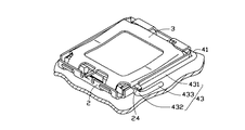
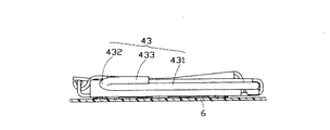
図2〜図5を参照すると、稼働アーム4はベース2に枢設される枢設部41と、枢設部41から凸設された押圧部42と、稼働部43とを備え、前記稼働部43はまた稼働部43から延伸接続部431と、接続部431の末端から伸び且つ曲がる曲がり部432と、曲がり部432の末端から伸びる操作部433とを備え、その中、曲がり部432は半円形にさせ、操作部433は接続部431と平行とされ、曲がり部432と操作部433は同一の平面であって且つ前記曲がり部432と枢設部41の平面に対して回路基板6から離れる方向に伸び、それで、電気コネクタ1を閉じる時、操作部433と回路基板6の距離は接続部431と回路基板6の距離より大きい。稼働アーム4の枢設部41はベース2の第二枢設端22に枢設され、稼働部43を外力によって水平と垂直位置の間に回転させ、且つ、押圧部42を回転させ、こうして、蓋体3の鉤32を押さえるあるいは緩める。
Referring to FIGS. 2 to 5, the operating arm 4 includes a
図3と図4を参照すると、電気コネクタ1を開ける時、稼働アーム4の接続部431が垂直位置にある。LGAチップモジュール5がベース2の受け部23に取り付けられた時、蓋体3を回転し、ケース33をLGAチップモジュール5に被せ、こうして、蓋3の鉤32は稼働アーム4の押圧部42にちょうど向かわせ、稼働部43を回転し、押圧部42を蓋体3の鉤32に押さえるまでいっしょに回転させ、稼働アーム4の接続部431を水平位置にさせ、こうして、稼働アーム4の接続部431がベース2の鉤24に引っ掛けさせるので、動きを止め、そこで、蓋体3のケース33をLGAチップモジュール5に押さえて、しっかりと接続するのに必要な支持力を提供する。
Referring to FIGS. 3 and 4, when the
本発明の技術を通じて、稼働アーム4の稼働部43に曲がり部432と操作部433が設けられ、曲がり部432と操作部433の平面は接続部431と枢設部41の平面に対して傾斜して伸び、電気コネクタ1を閉じる時、操作部433と回路基板6の距離は接続部431と回路基板6の距離よりおおきくし、こうして、操作空間を大きくさせ、操作者に稼働アーム4の操作部433を容易に制御させ、そこで、操作者が回路基板6あるいは他の電気素子に触れることは免れられ、操作に便利である。
Through the technology of the present invention, the
総じて、本発明の多数の特徴及び長所など、その構造及び機能が共に前述の記載により掲げられている。また前記の説明は、本発明に基づきなしうる細部の修正或は変更など、いずれも本発明の請求範囲に属するものとする。 In general, the structure and function of the present invention, including its many features and advantages, are all set forth in the foregoing description. All of the above description, such as modification or change of details that can be made based on the present invention, belongs to the scope of the present invention.
本発明は、一種の電気コネクタに関し、特にLGAチップモジュールと回路基板とを電気的に接続するために用いられ、且つ、より良好な操作性能を持っている電気コネクタに関するものである。 The present invention relates to an electrical connector, and more particularly, to an electrical connector that is used to electrically connect an LGA chip module to a circuit board and has better operability.
1 電気コネクタ
2 ベース
3 蓋
4 稼働アーム
5 LGAチップモジュール
6 回路基板
21 第一枢設端
22 第二枢設端
23 受け部
31 枢設端
32 鉤
33 ケース
41 枢設部
42 押圧部
43 稼働部
431 接続部
432 曲り部
433 操作部
Claims (17)
回路基板に取付けられ、チップモジュールを搭載することに用いられるベースと、
ベースに可動的に設けられる蓋体と、
ベースに可動的に設けられた枢設部と枢設部から延びる稼働部を含む稼働アームと、を備え、
前記稼働部はまた接続部と曲がり部及び操作部を含み、前記電気コネクタが閉じる時、操作部と回路基板の間の距離が接続部と回路基板の距離より大きいことを特徴とする電気コネクタ。 An electrical connector used to electrically connect a chip module and a circuit board,
A base attached to the circuit board and used to mount the chip module;
A lid movably provided on the base,
An operating arm including an operating portion movably provided on the base and an operating portion extending from the pivoting portion,
The electrical connector according to claim 1, wherein the operating part further includes a connecting part, a bending part, and an operating part, wherein when the electrical connector is closed, a distance between the operating part and the circuit board is larger than a distance between the connecting part and the circuit board.
回路基板に取付けられ、チップモジュールを搭載することに用いられるベースと、
ベースに可動的に設けられる蓋体と、
ベースに可動的に設けられた枢設部と枢設部から延びる稼働部を含む稼働アームと、を備え、
稼働部に枢設部から延びる接続部と前記接続部を曲げることによって形成した操作部が設けられ、前記電気コネクタを閉じる時、操作部において、操作部と回路基板の間の距離が接続部と回路基板の間の距離より大きい点が少なくとも一つあることを特徴とする電気コネクタ。 An electrical connector used to electrically connect a chip module and a circuit board,
A base attached to the circuit board and used to mount the chip module;
A lid movably provided on the base,
An operating arm including an operating portion movably provided on the base and an operating portion extending from the pivoting portion,
The operating portion is provided with a connecting portion extending from the pivot portion and an operating portion formed by bending the connecting portion, and when closing the electric connector, in the operating portion, the distance between the operating portion and the circuit board is equal to the connecting portion. An electrical connector comprising at least one point greater than a distance between circuit boards.
回路基板に取付けられ、チップモジュールを搭載することに用いられるベースと、
ベースに可動的に設けられる蓋体と、
ベースに可動的に設けられ、枢設部と枢設部から延びる稼働部を含む稼働アームと、を備え、
前記電気コネクタが閉じる時、稼働部の平面が回路基板の平面と傾斜して交わっていることを特徴とする電気コネクタ。 An electrical connector used to electrically connect a chip module and a circuit board,
A base attached to the circuit board and used to mount the chip module;
A lid movably provided on the base,
An operating arm movably provided on the base and including a pivot portion and an operating portion extending from the pivot portion,
The electrical connector according to claim 1, wherein when the electrical connector is closed, a plane of the operating portion is inclined and intersects a plane of the circuit board.
13. The electrical connector according to claim 12, wherein the base is provided with a hook that is connected to a connection portion of an operating arm.
Applications Claiming Priority (1)
| Application Number | Priority Date | Filing Date | Title |
|---|---|---|---|
| TW092208537U TW568455U (en) | 2003-05-09 | 2003-05-09 | Electrical connector |
Publications (1)
| Publication Number | Publication Date |
|---|---|
| JP2004335437A true JP2004335437A (en) | 2004-11-25 |
Family
ID=32505018
Family Applications (1)
| Application Number | Title | Priority Date | Filing Date |
|---|---|---|---|
| JP2003313272A Pending JP2004335437A (en) | 2003-05-09 | 2003-09-04 | Electrical connector |
Country Status (3)
| Country | Link |
|---|---|
| US (1) | US6908327B2 (en) |
| JP (1) | JP2004335437A (en) |
| TW (1) | TW568455U (en) |
Families Citing this family (13)
| Publication number | Priority date | Publication date | Assignee | Title |
|---|---|---|---|---|
| TWM254756U (en) * | 2003-11-21 | 2005-01-01 | Hon Hai Prec Ind Co Ltd | Socket connector assembly having pick-up cap |
| TWM255545U (en) * | 2003-12-12 | 2005-01-11 | Hon Hai Prec Ind Co Ltd | LGA socket |
| TWI299598B (en) | 2004-03-09 | 2008-08-01 | Hon Hai Prec Ind Co Ltd | Electrical connector |
| CN2733640Y (en) * | 2004-08-31 | 2005-10-12 | 汪应林 | Electric connector |
| DE102004063982A1 (en) * | 2004-11-09 | 2006-06-14 | Lumberg Connect Gmbh & Co. Kg | Contacting device for a chip card, in particular for a SIM card |
| TWM275553U (en) * | 2004-11-26 | 2005-09-11 | Hon Hai Prec Ind Co Ltd | Electrical connector |
| US6957973B1 (en) * | 2005-02-09 | 2005-10-25 | Hon Hai Precision Ind. Co., Ltd. | Land grid array connector and method of assembling an IC chip therein |
| TW200644350A (en) * | 2005-06-03 | 2006-12-16 | Guang-Jr Lai | Connecting base for LAG integrated circuit |
| CN201029121Y (en) * | 2007-03-05 | 2008-02-27 | 富士康(昆山)电脑接插件有限公司 | electronic card connector |
| TWM328132U (en) * | 2007-06-25 | 2008-03-01 | Hon Hai Prec Ind Co Ltd | Electrical connector |
| CN201160188Y (en) * | 2007-12-21 | 2008-12-03 | 富士康(昆山)电脑接插件有限公司 | electrical connector |
| US9192070B2 (en) * | 2011-02-28 | 2015-11-17 | Hewlett-Packard Development Company, L.P. | Spring loaded lid |
| US11382223B2 (en) * | 2015-06-30 | 2022-07-05 | Lear Corporation | Spring and damper system and method for producing same |
Family Cites Families (26)
| Publication number | Priority date | Publication date | Assignee | Title |
|---|---|---|---|---|
| JPH0668982B2 (en) * | 1990-07-24 | 1994-08-31 | 山一電機工業株式会社 | Socket for electrical parts |
| US5057031A (en) * | 1990-08-15 | 1991-10-15 | Aries Electronics, Inc. | Zero insertion force pin grid array test socket |
| US5183361A (en) * | 1991-11-04 | 1993-02-02 | Jackson Ho | Punching and binding machine |
| US5391208A (en) * | 1992-09-22 | 1995-02-21 | Highland Supply Corporation | Method and apparatus for stemming flowers |
| CA2115403C (en) * | 1994-02-10 | 1998-08-04 | Fu-Yu Hsu | Electrical connector with zif socket |
| US6280222B1 (en) * | 2000-07-25 | 2001-08-28 | Hon Hai Precision Ind. Co., Ltd. | LGA socket with reliable securing mechanism |
| US6485320B1 (en) * | 2001-12-19 | 2002-11-26 | Hon Hai Precision Ind. Co., Ltd. | Land grid array connector assembly |
| US6626691B2 (en) * | 2001-12-19 | 2003-09-30 | Hon Hai Precision Ind. Co., Ltd. | Pick up cap for BGA socket |
| TW532713U (en) * | 2002-06-13 | 2003-05-11 | Hon Hai Prec Ind Co Ltd | Retainer device |
| TW545752U (en) * | 2002-07-26 | 2003-08-01 | Hon Hai Prec Ind Co Ltd | Electrical connector assembly |
| US6735085B2 (en) * | 2002-08-15 | 2004-05-11 | Hon Hai Precision Ind. Co., Ltd. | Foldable retention device for land grid array connector assembly |
| TW581329U (en) * | 2002-10-04 | 2004-03-21 | Hon Hai Prec Ind Co Ltd | Electrical connector assembly |
| TW560718U (en) * | 2002-11-15 | 2003-11-01 | Hon Hai Prec Ind Co Ltd | Electrical connector |
| TW555212U (en) * | 2002-12-06 | 2003-09-21 | Hon Hai Prec Ind Co Ltd | Electrical connector |
| US6676429B1 (en) * | 2002-12-10 | 2004-01-13 | Hon Hai Precision Ind. Co., Ltd. | Land grid array connector assembly |
| TW551635U (en) * | 2002-12-13 | 2003-09-01 | Hon Hai Prec Ind Co Ltd | Electrical connector |
| TW549644U (en) * | 2002-12-13 | 2003-08-21 | Hon Hai Prec Ind Co Ltd | Electrical connector |
| TW549635U (en) * | 2002-12-20 | 2003-08-21 | Hon Hai Prec Ind Co Ltd | Strengthened belectrical connector |
| TW549655U (en) * | 2002-12-20 | 2003-08-21 | Hon Hai Prec Ind Co Ltd | An electrical connector |
| US6758691B1 (en) * | 2003-04-10 | 2004-07-06 | Hon Hai Precision Ind. Co., Ltd | Land grid array connector assembly with sliding lever |
| US6726500B1 (en) * | 2003-04-17 | 2004-04-27 | Hon Hai Precision Ind. Co., Ltd. | Land grid array connector assembly with reinforcement |
| US6722909B1 (en) * | 2003-04-17 | 2004-04-20 | Hon Hai Precision Ind. Co., Ltd. | Electrical connector with lever retainer |
| TW568422U (en) * | 2003-05-14 | 2003-12-21 | Hon Hai Prec Ind Co Ltd | Electrical connector |
| TW568398U (en) * | 2003-05-16 | 2003-12-21 | Hon Hai Prec Ind Co Ltd | Electrical connector |
| US6685494B1 (en) * | 2003-05-20 | 2004-02-03 | Hon Hai Precision Ind. Co., Ltd. | Electrical connector with stiffener |
| US6776642B1 (en) * | 2003-07-15 | 2004-08-17 | Hon Hai Precision Ind. Co., Ltd. | Electrical connector assembly having metal clip for pressing loaded LGA IC module |
-
2003
- 2003-05-09 TW TW092208537U patent/TW568455U/en not_active IP Right Cessation
- 2003-09-04 JP JP2003313272A patent/JP2004335437A/en active Pending
- 2003-09-26 US US10/672,800 patent/US6908327B2/en not_active Expired - Fee Related
Also Published As
| Publication number | Publication date |
|---|---|
| US6908327B2 (en) | 2005-06-21 |
| TW568455U (en) | 2003-12-21 |
| US20050026490A1 (en) | 2005-02-03 |
Similar Documents
| Publication | Publication Date | Title |
|---|---|---|
| CN206524414U (en) | A kind of binding post that can be spacing | |
| KR19990082906A (en) | Card reader connector | |
| US20080220643A1 (en) | Land grid array connector having improved cover | |
| JP2005056824A (en) | Electrical connector | |
| TWM302145U (en) | Electrical connector | |
| JP2001118618A (en) | connector | |
| JP3120137U (en) | Electrical connector | |
| JP4122327B2 (en) | Electrical connector with removal plate | |
| JPH0734382B2 (en) | Contact holding device in socket for electric parts | |
| US7878837B2 (en) | Socket connector having improved actuating mechanism for driving moving plate | |
| CN2405330Y (en) | Inserting slot electric connector | |
| CN201638970U (en) | Electronic card connector | |
| US20050142913A1 (en) | Electrical card connector with door | |
| CN103380472B (en) | Key card inserting electricity-taking switch | |
| CN201072829Y (en) | Electrical connector | |
| US7575460B2 (en) | IC socket | |
| CN106888287A (en) | Card connector and its Kato disk | |
| TWI375364B (en) | Socket | |
| CN112516586B (en) | Composite handle | |
| CN102956394B (en) | Rocker switch | |
| CN2736904Y (en) | push switch | |
| CN202231231U (en) | Electric connector | |
| CN2750365Y (en) | Computer panel combination | |
| TWM439279U (en) | Electrical connector | |
| CN201112891Y (en) | Electric connector |
Legal Events
| Date | Code | Title | Description |
|---|---|---|---|
| A621 | Written request for application examination |
Free format text: JAPANESE INTERMEDIATE CODE: A621 Effective date: 20050112 |
|
| A131 | Notification of reasons for refusal |
Free format text: JAPANESE INTERMEDIATE CODE: A131 Effective date: 20070710 |
|
| A02 | Decision of refusal |
Free format text: JAPANESE INTERMEDIATE CODE: A02 Effective date: 20071204 |