JP2004335455A - Solid electrolyte and all-solid battery containing it - Google Patents
Solid electrolyte and all-solid battery containing it Download PDFInfo
- Publication number
- JP2004335455A JP2004335455A JP2004119042A JP2004119042A JP2004335455A JP 2004335455 A JP2004335455 A JP 2004335455A JP 2004119042 A JP2004119042 A JP 2004119042A JP 2004119042 A JP2004119042 A JP 2004119042A JP 2004335455 A JP2004335455 A JP 2004335455A
- Authority
- JP
- Japan
- Prior art keywords
- solid electrolyte
- transition metal
- lithium
- solid
- metal element
- Prior art date
- Legal status (The legal status is an assumption and is not a legal conclusion. Google has not performed a legal analysis and makes no representation as to the accuracy of the status listed.)
- Granted
Links
Images


Classifications
-
- H—ELECTRICITY
- H01—ELECTRIC ELEMENTS
- H01B—CABLES; CONDUCTORS; INSULATORS; SELECTION OF MATERIALS FOR THEIR CONDUCTIVE, INSULATING OR DIELECTRIC PROPERTIES
- H01B1/00—Conductors or conductive bodies characterised by the conductive materials; Selection of materials as conductors
- H01B1/06—Conductors or conductive bodies characterised by the conductive materials; Selection of materials as conductors mainly consisting of other non-metallic substances
- H01B1/12—Conductors or conductive bodies characterised by the conductive materials; Selection of materials as conductors mainly consisting of other non-metallic substances organic substances
- H01B1/122—Ionic conductors
-
- H—ELECTRICITY
- H01—ELECTRIC ELEMENTS
- H01B—CABLES; CONDUCTORS; INSULATORS; SELECTION OF MATERIALS FOR THEIR CONDUCTIVE, INSULATING OR DIELECTRIC PROPERTIES
- H01B1/00—Conductors or conductive bodies characterised by the conductive materials; Selection of materials as conductors
- H01B1/06—Conductors or conductive bodies characterised by the conductive materials; Selection of materials as conductors mainly consisting of other non-metallic substances
-
- H—ELECTRICITY
- H01—ELECTRIC ELEMENTS
- H01M—PROCESSES OR MEANS, e.g. BATTERIES, FOR THE DIRECT CONVERSION OF CHEMICAL ENERGY INTO ELECTRICAL ENERGY
- H01M10/00—Secondary cells; Manufacture thereof
- H01M10/05—Accumulators with non-aqueous electrolyte
- H01M10/056—Accumulators with non-aqueous electrolyte characterised by the materials used as electrolytes, e.g. mixed inorganic/organic electrolytes
- H01M10/0561—Accumulators with non-aqueous electrolyte characterised by the materials used as electrolytes, e.g. mixed inorganic/organic electrolytes the electrolyte being constituted of inorganic materials only
-
- H—ELECTRICITY
- H01—ELECTRIC ELEMENTS
- H01M—PROCESSES OR MEANS, e.g. BATTERIES, FOR THE DIRECT CONVERSION OF CHEMICAL ENERGY INTO ELECTRICAL ENERGY
- H01M10/00—Secondary cells; Manufacture thereof
- H01M10/05—Accumulators with non-aqueous electrolyte
- H01M10/056—Accumulators with non-aqueous electrolyte characterised by the materials used as electrolytes, e.g. mixed inorganic/organic electrolytes
- H01M10/0561—Accumulators with non-aqueous electrolyte characterised by the materials used as electrolytes, e.g. mixed inorganic/organic electrolytes the electrolyte being constituted of inorganic materials only
- H01M10/0562—Solid materials
-
- H—ELECTRICITY
- H01—ELECTRIC ELEMENTS
- H01M—PROCESSES OR MEANS, e.g. BATTERIES, FOR THE DIRECT CONVERSION OF CHEMICAL ENERGY INTO ELECTRICAL ENERGY
- H01M2300/00—Electrolytes
- H01M2300/0017—Non-aqueous electrolytes
- H01M2300/0065—Solid electrolytes
-
- Y—GENERAL TAGGING OF NEW TECHNOLOGICAL DEVELOPMENTS; GENERAL TAGGING OF CROSS-SECTIONAL TECHNOLOGIES SPANNING OVER SEVERAL SECTIONS OF THE IPC; TECHNICAL SUBJECTS COVERED BY FORMER USPC CROSS-REFERENCE ART COLLECTIONS [XRACs] AND DIGESTS
- Y02—TECHNOLOGIES OR APPLICATIONS FOR MITIGATION OR ADAPTATION AGAINST CLIMATE CHANGE
- Y02E—REDUCTION OF GREENHOUSE GAS [GHG] EMISSIONS, RELATED TO ENERGY GENERATION, TRANSMISSION OR DISTRIBUTION
- Y02E60/00—Enabling technologies; Technologies with a potential or indirect contribution to GHG emissions mitigation
- Y02E60/10—Energy storage using batteries
Landscapes
- Chemical & Material Sciences (AREA)
- Manufacturing & Machinery (AREA)
- Inorganic Chemistry (AREA)
- Engineering & Computer Science (AREA)
- Physics & Mathematics (AREA)
- Chemical Kinetics & Catalysis (AREA)
- Electrochemistry (AREA)
- General Chemical & Material Sciences (AREA)
- General Physics & Mathematics (AREA)
- Condensed Matter Physics & Semiconductors (AREA)
- Spectroscopy & Molecular Physics (AREA)
- Secondary Cells (AREA)
- Conductive Materials (AREA)
Abstract
【課題】 湿潤雰囲気下でも、イオン伝導性の低下を抑制することができる固体電解質、ならびにそのような固体電解質を用いる全固体電池を提供する。
【解決手段】 Li、O、Pおよび遷移金属元素からなる固体電解質。
【選択図】図1
PROBLEM TO BE SOLVED: To provide a solid electrolyte capable of suppressing a decrease in ion conductivity even under a humid atmosphere, and an all-solid battery using such a solid electrolyte.
A solid electrolyte comprising Li, O, P and a transition metal element.
[Selection diagram] Fig. 1
Description
本発明は、全固体電池、特に全固体リチウム二次電池に用いられる固体電解質、ならびにその固体電解質を含む全固体電池に関する。 The present invention relates to a solid electrolyte used for an all-solid battery, particularly an all-solid lithium secondary battery, and an all-solid battery including the solid electrolyte.
近年、パーソナルコンピュータ、携帯電話などのポータブル機器の開発に伴い、その電源としての電池の需要が、非常に大きくなってきている。
上記のような用途に用いられる電池においては、従来から、イオンを移動させる媒体として、有機溶媒のような液体からなる電解質が使用されている。このため、電池からの電解質の漏液などの問題が生じる可能性がある。
In recent years, with the development of portable devices such as personal computers and mobile phones, the demand for batteries as power sources has become extremely large.
In a battery used for the above-described applications, an electrolyte made of a liquid such as an organic solvent has been used as a medium for moving ions. For this reason, there is a possibility that problems such as electrolyte leakage from the battery may occur.
このような問題を解決するために、液体の電解質の代わりに、固体電解質を用いる全固体電池の開発が進められている。中でも、全固体リチウム二次電池は、高エネルギー密度を得ることができる電池として各方面で盛んに研究が行われている。これは、Liが小さな原子量を有し、そのイオン化傾向が最も大きく、また電気化学的に最も卑な金属であるため、例えば、Li金属を負極活物質に用いると高い起電力が得られるからである。 In order to solve such a problem, development of an all-solid-state battery using a solid electrolyte instead of a liquid electrolyte has been promoted. Above all, all-solid lithium secondary batteries have been actively studied in various fields as batteries capable of obtaining high energy density. This is because Li has a small atomic weight, has the highest ionization tendency, and is the most electrochemically noble metal.For example, when Li metal is used for the negative electrode active material, a high electromotive force is obtained. is there.
上記全固体リチウム二次電池に用いられる固体電解質としては、例えば、ハロゲン化リチウム、窒化リチウム、リチウム酸素酸塩、およびこれらの誘導体などが知られている。特に、オルトリン酸リチウム(Li3PO4)に窒素(N)を導入して得られる窒化リン酸リチウム(LixPOyNz(x=2.8、3z+2y=7.8))は、酸化物系の材料であるにも関わらず、(1〜2)×10-6S/cmの非常に高いリチウムイオン伝導性を有することが報告されている(特許文献1参照)。
ところが、上記窒化リン酸リチウムが湿潤雰囲気に曝されると、窒化リン酸リチウムを構成するリン原子(P)は、湿潤雰囲気中の水分子と反応する。このとき、リン原子は、+5価の酸化状態からより低い酸化状態に還元される。これにより、窒化リン酸リチウムが分解してしまい、そのイオン伝導性が著しく低下する。 However, when the lithium nitride phosphate is exposed to a humid atmosphere, the phosphorus atoms (P) constituting the lithium nitride phosphate react with water molecules in the humid atmosphere. At this time, the phosphorus atom is reduced from a pentavalent oxidation state to a lower oxidation state. As a result, the lithium nitride phosphate is decomposed, and the ionic conductivity is significantly reduced.
このようなイオン伝導性の低下が生じると、窒化リン酸リチウムからなる固体電解質を用いる全固体電池では、内部インピーダンスが増加する。このため、その充放電レート特性が著しく損なわれてしまう。
さらに、湿潤雰囲気下でのイオン伝導性の低下は、リン酸リチウムでも見られる。従って、このようなイオン伝導性の低下は、リン酸リチウムを骨格構造に持つ固体電解質材料において、本質的な問題である。
When such a decrease in ionic conductivity occurs, the internal impedance of an all-solid-state battery using a solid electrolyte made of lithium nitride phosphate increases. For this reason, the charge / discharge rate characteristics are significantly impaired.
Further, a decrease in ionic conductivity under a humid atmosphere is also observed in lithium phosphate. Therefore, such a decrease in ionic conductivity is an essential problem in a solid electrolyte material having a lithium phosphate skeleton structure.
そこで、本発明は、湿潤雰囲気下でも、イオン伝導性の低下を抑制することができる固体電解質、ならびにそのような固体電解質を用いる全固体電池を提供することを目的とする。 Therefore, an object of the present invention is to provide a solid electrolyte capable of suppressing a decrease in ion conductivity even under a humid atmosphere, and an all-solid battery using such a solid electrolyte.
本発明は、Li、O、Pおよび遷移金属元素からなる固体電解質に関する。 The present invention relates to a solid electrolyte composed of Li, O, P and a transition metal element.
上記固体電解質において、遷移金属元素は、Ti、V、Cr、Mn、Fe、Co、Ni、Cu、Zr、Nb、Mo、Ru、Ag、Ta、W、PtおよびAuよりなる群から選択される少なくとも1種であることが好ましい。 In the above solid electrolyte, the transition metal element is selected from the group consisting of Ti, V, Cr, Mn, Fe, Co, Ni, Cu, Zr, Nb, Mo, Ru, Ag, Ta, W, Pt and Au. Preferably, at least one kind is used.
上記固体電解質が、以下の式:
LixPTyOz
(ここで、Tは遷移金属元素を表し、x=2〜7、y=0.01〜1、z=3.5〜8)によって表される組成物であることが好ましい。
The solid electrolyte has the following formula:
Li x PT y O z
(Here, T represents a transition metal element, x = 2 to 7, y = 0.01 to 1, and z = 3.5 to 8).
上記式において、x=2〜3、y=0.01〜0.5、およびz=3.5〜4であることがさらに好ましい。 In the above formula, it is more preferable that x = 2 to 3, y = 0.01 to 0.5, and z = 3.5 to 4.
上記式において、x=2〜3、y=0.01〜1、およびz=3.505〜7であることがさらに好ましい。 In the above formula, it is more preferable that x = 2 to 3, y = 0.01 to 1, and z = 3.505 to 7.
上記式において、x=2.01〜7、y=0.01〜1、およびz=3.52〜8であることがさらに好ましい。 In the above formula, it is more preferable that x = 2.01 to 7, y = 0.01 to 1, and z = 3.52 to 8.
本発明は、また、正極、負極、および正極と負極との間に配置された、上記固体電解質を備える全固体電池に関する。 The present invention also relates to an all-solid battery including the positive electrode, the negative electrode, and the above-described solid electrolyte disposed between the positive electrode and the negative electrode.
本発明により、湿潤雰囲気下でも、イオン伝導性の低下を抑制することができる固体電解質を提供することができる。 According to the present invention, it is possible to provide a solid electrolyte capable of suppressing a decrease in ion conductivity even under a humid atmosphere.
以下に、本発明の固体電解質およびその固体電解質を用いた全固体電池について説明する。
本発明の固体電解質は、リチウム(Li)、リン(P)、酸素(O)ならびに遷移金属元素Tからなる。例えば、この固体電解質は、リン酸リチウムと遷移金属元素Tとからなる。この場合、遷移金属元素Tは、原子レベルでリン酸リチウムに取り込まれていてもよいし、リン酸リチウムと遷移金属元素Tが粒子レベルで混合されていてもよい。また、本発明の固体電解質は、上記遷移金属元素Tの代わりに、遷移金属酸化物、またはリチウム含有遷移金属酸化物と、リン酸リチウムとから構成されてもよい。
Hereinafter, the solid electrolyte of the present invention and an all-solid battery using the solid electrolyte will be described.
The solid electrolyte of the present invention comprises lithium (Li), phosphorus (P), oxygen (O), and a transition metal element T. For example, the solid electrolyte includes lithium phosphate and a transition metal element T. In this case, the transition metal element T may be incorporated into lithium phosphate at an atomic level, or lithium phosphate and the transition metal element T may be mixed at a particle level. Further, the solid electrolyte of the present invention may be composed of a transition metal oxide or a lithium-containing transition metal oxide and lithium phosphate instead of the transition metal element T.
このように、本発明の固体電解質には、遷移金属元素Tが含まれている。遷移金属元素Tは、リン原子と比較して、還元性が高く、かつ容易に価数が変化し得る。このような遷移金属元素Tを含む固体電解質が湿潤雰囲気に曝された場合、リン原子よりも、遷移金属元素Tが優先的に還元される。これにより、リン原子の大部分は、還元されずにもとの酸化数が維持され、固体電解質の分解が抑制される。従って、固体電解質の分解に起因するイオン伝導性の低下も抑制されることになる。 As described above, the transition metal element T is contained in the solid electrolyte of the present invention. The transition metal element T has a higher reducing property than the phosphorus atom and can easily change its valence. When such a solid electrolyte containing the transition metal element T is exposed to a humid atmosphere, the transition metal element T is preferentially reduced over phosphorus atoms. Thereby, most of the phosphorus atoms are not reduced and the original oxidation number is maintained, and the decomposition of the solid electrolyte is suppressed. Therefore, a decrease in ion conductivity due to the decomposition of the solid electrolyte is also suppressed.
また、上記固体電解質を、式LixPTyOzで表した場合、x=2〜7、y=0.01〜1、およびz=3.5〜8であることが好ましい。 Further, the solid electrolyte, when expressed by the formula Li x PT y O z, x = 2~7, it is preferable y = 0.01 to 1, and a z = 3.5 to 8.
本発明においては、上記のように、リン原子の還元を、遷移金属元素Tを添加することにより抑制している。このため、前記固体電解質を構成するリン酸リチウム中のリン原子に対する遷移金属元素Tのモル比y((Tのモル数)/(Pのモル数))が重要になる。上記のように、そのモル比yは、0.01〜1であることが望ましい。 In the present invention, as described above, the reduction of the phosphorus atom is suppressed by adding the transition metal element T. For this reason, the molar ratio y ((moles of T) / (moles of P)) of the transition metal element T to phosphorus atoms in the lithium phosphate constituting the solid electrolyte becomes important. As described above, the molar ratio y is desirably 0.01 to 1.
リン原子に対する遷移金属元素Tのモル比yが、0.01未満である場合には、リン原子の還元を十分に抑制することができない。
一方、リン原子に対する遷移金属元素のモル比が1を超える固体電解質と還元性の強いLi金属とを接触させた場合、前記固体電解質とLi金属との間に不可逆な反応が生じる可能性がある。固体電解質とLi金属との間に不可逆な反応が生じると、Li金属は金属色を示さなくなる。また、このような固体電解質においては、固体電解質を構成するリン酸リチウムの骨格構造が壊れ、固体電解質のイオン伝導性が低下することになる。
When the molar ratio y of the transition metal element T to the phosphorus atom is less than 0.01, the reduction of the phosphorus atom cannot be sufficiently suppressed.
On the other hand, when a solid electrolyte having a molar ratio of a transition metal element to a phosphorus atom of more than 1 is brought into contact with a highly reducing Li metal, an irreversible reaction may occur between the solid electrolyte and the Li metal. . If an irreversible reaction occurs between the solid electrolyte and the Li metal, the Li metal no longer exhibits a metallic color. In such a solid electrolyte, the skeleton structure of lithium phosphate constituting the solid electrolyte is broken, and the ionic conductivity of the solid electrolyte is reduced.
更に、固体電解質が遷移金属元素Tの単体とリン酸リチウムとからなる場合、前記モル比yが0.5を超えると電子伝導性が増加する。このような電子伝導性が増加した固体電解質を全固体電池の固体電解質として用いると、その全固体電池が充電状態にある場合に、当該固体電解質が自己放電する可能性がある。 Further, when the solid electrolyte is composed of a simple substance of the transition metal element T and lithium phosphate, when the molar ratio y exceeds 0.5, the electron conductivity increases. When such a solid electrolyte having increased electron conductivity is used as a solid electrolyte of an all-solid battery, the solid electrolyte may self-discharge when the all-solid battery is in a charged state.
また、上記固体電解質においては、種々の遷移金属元素Tの単体の他に、種々の遷移金属酸化物またはリチウム含有遷移金属酸化物を用いてもよい。用いる遷移金属元素Tの単体、遷移金属酸化物またはリチウム含有遷移金属酸化物の種類やリン酸リチウムとの混合比等によって、固体電解質の組成は変化する。このため、xは2〜7であることが好ましく、zは3.5〜8であることが好ましい。 Further, in the above-mentioned solid electrolyte, various transition metal oxides or lithium-containing transition metal oxides may be used in addition to the simple substance of various transition metal elements T. The composition of the solid electrolyte varies depending on the type of the transition metal element T used, the type of the transition metal oxide or the lithium-containing transition metal oxide, the mixing ratio with lithium phosphate, and the like. For this reason, x is preferably 2 to 7, and z is preferably 3.5 to 8.
次に、本発明の固体電解質の作製方法について説明する。
本発明の固体電解質は、例えば、リン酸リチウムおよび遷移金属元素Tの単体を原料として作製することができる。また、上記のように、遷移金属元素Tの単体の代わりに、遷移金属酸化物、またはリチウム含有遷移金属酸化物を用いてもよい。
Next, a method for producing the solid electrolyte of the present invention will be described.
The solid electrolyte of the present invention can be produced using, for example, a simple substance of lithium phosphate and transition metal element T as raw materials. As described above, a transition metal oxide or a lithium-containing transition metal oxide may be used instead of the simple substance of the transition metal element T.
また、用いられる代表的なリン酸リチウムとしては、オルトリン酸リチウム(Li3PO4)が挙げられるが、他のリン酸リチウム(LiPO3)やLi2OとP2O5の混合物などを用いることもできる。 A typical lithium phosphate used is lithium orthophosphate (Li 3 PO 4 ), but other lithium phosphate (LiPO 3 ) or a mixture of Li 2 O and P 2 O 5 is used. You can also.
以下に、リン酸リチウムと、遷移金属元素Tの単体、遷移金属酸化物またはリチウム含有遷移金属酸化物とから固体電解質を作製する方法について説明する。 Hereinafter, a method for producing a solid electrolyte from lithium phosphate and a simple substance of the transition metal element T, a transition metal oxide or a lithium-containing transition metal oxide will be described.
(A)遷移金属元素Tの単体およびリン酸リチウムからなる固体電解質
本発明の固体電解質は、種々の方法で作製することができる。例えば、固体電解質の薄膜を作製する場合、その作製方法としては、真空下で行われる薄膜作製法を用いることができる。
(A) Solid electrolyte composed of simple substance of transition metal element T and lithium phosphate The solid electrolyte of the present invention can be produced by various methods. For example, when a thin film of a solid electrolyte is manufactured, a thin film manufacturing method performed under vacuum can be used as the manufacturing method.
上記真空下で行われる薄膜作製方法としては、スパッタリング法、蒸着法などが挙げられる。 Examples of the method for forming a thin film performed under vacuum include a sputtering method and an evaporation method.
上記スパッタリング法としては、例えば、マグネトロン、高周波発生装置などの手段により、アルゴン(Ar)雰囲気下、酸素(O2)雰囲気下、あるいはアルゴンと酸素との混合雰囲気下において、ターゲットをスパッタするスパッタリング法(例えば、rfマグネトロンスパッタリング法)などが挙げられる。 As the sputtering method, for example, a sputtering method in which a target is sputtered by means of a magnetron, a high-frequency generator, or the like in an argon (Ar) atmosphere, an oxygen (O 2 ) atmosphere, or a mixed atmosphere of argon and oxygen. (For example, rf magnetron sputtering method).
蒸着法としては、例えば、抵抗に通電することにより生じる熱で蒸着源を加熱することにより蒸着を行う抵抗加熱蒸着法、イオンビームにより蒸着源にイオンビームを照射して蒸着を行うイオンビーム蒸着法、蒸着源に電子ビームを照射して蒸着源を加熱することにより蒸着を行う電子ビーム蒸着法、蒸着源にレーザーを照射して蒸着源を加熱することにより蒸着を行うレーザーアブレーション法などが挙げられる。 Examples of the vapor deposition method include a resistance heating vapor deposition method in which vapor deposition is performed by heating a vapor deposition source with heat generated by energizing a resistor, and an ion beam vapor deposition method in which a vapor deposition source is irradiated with an ion beam by an ion beam to perform vapor deposition. An electron beam evaporation method in which an evaporation source is irradiated with an electron beam to heat the evaporation source to perform evaporation, and a laser ablation method in which laser is applied to the evaporation source to heat the evaporation source to perform evaporation, and the like. .
例えば、スパッタリング法を用いて、固体電解質を作製する場合、ターゲットとして、リン酸リチウムターゲットと遷移金属元素ターゲットの両方のターゲットが用いられる。また、リン酸リチウムに、遷移金属元素Tの単体を所定の混合比で混合してものを、ターゲットとして用いることもできる。 For example, when a solid electrolyte is manufactured by a sputtering method, both targets of a lithium phosphate target and a transition metal element target are used. Alternatively, a mixture of lithium phosphate and a simple substance of the transition metal element T at a predetermined mixing ratio can be used as a target.
蒸着法を用いて固体電解質の薄膜を作製する場合には、リン酸リチウム蒸着源と遷移金属元素蒸着源の両方が、蒸着源として用いられる。また、リン酸リチウムに、遷移金属元素Tの単体を所定の混合比で混合したものを蒸着源として用いることもできる。 When a thin film of a solid electrolyte is formed using an evaporation method, both a lithium phosphate evaporation source and a transition metal element evaporation source are used as the evaporation source. Alternatively, a mixture of lithium phosphate and a simple substance of the transition metal element T at a predetermined mixing ratio can be used as the evaporation source.
リン酸リチウムに遷移金属元素Tの単体を混合したものを、ターゲットまたは蒸着源として用いる場合、その混合比は、所望の固体電解質の組成に応じて、適宜調節される。 When a mixture of lithium phosphate and a simple substance of the transition metal element T is used as a target or an evaporation source, the mixture ratio is appropriately adjusted according to the desired composition of the solid electrolyte.
蒸着法を用いて固体電解質を作製する場合には、リン酸リチウムの蒸着に抵抗加熱蒸着法を用い、遷移金属元素Tの蒸着に電子ビーム蒸着法を用いるというように、リン酸リチウムおよび遷移金属元素Tに、異なる蒸着法を適用することも可能である。 When a solid electrolyte is manufactured by using an evaporation method, a resistance heating evaporation method is used for depositing lithium phosphate, and an electron beam evaporation method is used for depositing a transition metal element T. It is also possible to apply different evaporation methods to the element T.
固体電解質を作製する場合に用いられる遷移金属元素Tとしては、チタン(Ti)、バナジウム(V)、クロム(Cr)、マンガン(Mn)、鉄(Fe)、コバルト(Co)、ニッケル(Ni)、銅(Cu)、ジルコニウム(Zr)、ニオブ(Nb)、モリブデン(Mo)、ルテニウム(Ru)、銀(Ag)、タンタル(Ta)、タングステン(W)、白金(Pt)、および金(Au)よりなる群から選択される少なくとも1種を用いることが好ましい。もちろん、本発明の効果を損なわなければ、上記以外の遷移金属元素を用いることもできる。 The transition metal element T used for producing the solid electrolyte includes titanium (Ti), vanadium (V), chromium (Cr), manganese (Mn), iron (Fe), cobalt (Co), and nickel (Ni). , Copper (Cu), zirconium (Zr), niobium (Nb), molybdenum (Mo), ruthenium (Ru), silver (Ag), tantalum (Ta), tungsten (W), platinum (Pt), and gold (Au) It is preferable to use at least one selected from the group consisting of: Of course, other transition metal elements can also be used as long as the effects of the present invention are not impaired.
このような固体電解質において、Li原子、リン原子および酸素原子の価数は、それぞれ+1価、+5価および−2価となる。遷移金属元素Tは、リン酸リチウム中に金属の状態で取り込まれていると考えられるため、0価とみなすことができる。 In such a solid electrolyte, the valences of Li atom, phosphorus atom and oxygen atom are +1 valence, +5 valence and -2 valence, respectively. Since the transition metal element T is considered to be incorporated in the lithium phosphate in a metal state, it can be regarded as having zero valence.
また、このような固体電解質を式LiαPTβOγで表した場合、α=2〜3、β=0.01〜0.5、およびγ=3.5〜4であることが好ましい。 When such a solid electrolyte is represented by the formula LiαPTβOγ, it is preferable that α = 2 to 3, β = 0.01 to 0.5, and γ = 3.5 to 4.
(B)遷移金属酸化物とリン酸リチウムからなる固体電解質
本発明の固体電解質は、遷移金属酸化物とリン酸リチウムとから作製することもできる。この場合も、上記(A)のようなスパッタリング法や蒸着法を用いることができる。
(B) Solid Electrolyte Consisting of Transition Metal Oxide and Lithium Phosphate The solid electrolyte of the present invention can also be prepared from a transition metal oxide and lithium phosphate. Also in this case, a sputtering method or an evaporation method as described in (A) above can be used.
用いられる遷移金属酸化物としては、酸化チタン(TiO2)、酸化バナジウム(V2O5、VO2)、酸化クロム(Cr2O3)、酸化マンガン(MnO2、Mn2O3)、酸化鉄(Fe2O3、Fe3O4)、酸化コバルト(Co3O4、CoO)、酸化ニッケル(Ni3O4、NiO)、酸化銅(CuO)、酸化ジルコニウム(ZrO2)、酸化ニオブ(Nb2O5)、酸化モリブデン(MoO2、MoO3)、酸化ルテニウム(RuO2)、酸化銀(Ag2O、Ag2O2)、酸化タンタル(Ta2O5)、酸化タングステン(WO3、WO2)、酸化白金(PtO、PtO2)、および酸化金(Au2O3)よりなる群から選択される少なくとも1種を用いることが好ましい。もちろん、本発明の効果を損なわなけならば、これら以外の酸化物を用いることもできる。 As the transition metal oxide used, titanium oxide (TiO 2 ), vanadium oxide (V 2 O 5 , VO 2 ), chromium oxide (Cr 2 O 3 ), manganese oxide (MnO 2 , Mn 2 O 3 ), oxide Iron (Fe 2 O 3 , Fe 3 O 4 ), cobalt oxide (Co 3 O 4 , CoO), nickel oxide (Ni 3 O 4 , NiO), copper oxide (CuO), zirconium oxide (ZrO 2 ), niobium oxide (Nb 2 O 5 ), molybdenum oxide (MoO 2 , MoO 3 ), ruthenium oxide (RuO 2 ), silver oxide (Ag 2 O, Ag 2 O 2 ), tantalum oxide (Ta 2 O 5 ), tungsten oxide (WO) 3, WO 2), platinum oxide (PtO, PtO 2), and gold oxide (Au 2 O 3) is preferably used at least one selected from the group consisting of. Of course, other oxides can be used as long as the effects of the present invention are not impaired.
このような固体電解質を式LiαPTβOγで表した場合、α=2〜3、β=0.01〜1、およびγ=3.505〜7であることが好ましい。 When such a solid electrolyte is represented by the formula LiαPTβOγ, it is preferable that α = 2 to 3, β = 0.01 to 1, and γ = 3.505 to 7.
また、遷移金属酸化物とリン酸リチウムとからなる固体電解質は、式LiaPOb−TcOdで表すこともできる。この場合、a=2〜3、b=3.5〜4、c=0.01〜1、およびd=0.005〜3であることが好ましい。 Further, the solid electrolyte consisting of a transition metal oxide and the lithium phosphate may also be represented by the formula Li a PO b -T c O d . In this case, it is preferable that a = 2 to 3, b = 3.5 to 4, c = 0.01 to 1, and d = 0.005 to 3.
(C)リチウム含有遷移金属酸化物とリン酸リチウムからなる固体電解質
また、リチウム含有遷移金属酸化物とリン酸リチウムとから、本発明の固体電解質を作製することもできる。このような固体電解質を、式LiαPTβOγで表した場合、α=2.01〜7、β=0.01〜1、およびγ=3.52〜8であることが好ましい。
(C) Solid Electrolyte Consisting of Lithium-Containing Transition Metal Oxide and Lithium Phosphate The solid electrolyte of the present invention can also be prepared from a lithium-containing transition metal oxide and lithium phosphate. When such a solid electrolyte is represented by the formula LiαPTβOγ, it is preferable that α = 2.01 to 7, β = 0.01 to 1, and γ = 3.52 to 8.
また、リチウム含有遷移金属酸化物とリン酸リチウムとからなる固体電解質を、式LiaPOb−LicTdOeで表すこともできる。この場合、a=2〜3、b=3.5〜4、c=0.01〜4、d=0.01〜1、およびe=0.02〜4であることが好ましい。 Further, a solid electrolyte consisting of a lithium-containing transition metal oxide and the lithium phosphate may be represented by the formula Li a PO b -Li c T d O e. In this case, it is preferable that a = 2-3, b = 3.5-4, c = 0.01-4, d = 0.01-1 and e = 0.02-4.
上記リチウム含有遷移金属酸化物としては、チタン酸リチウム(Li4TiO4、Li2TiO3)、バナジン酸リチウム(Li3VO4、LiVO3)、クロム酸リチウム(Li2CrO4)、マンガン酸リチウム(LiMnO4、Li2MnO2、LiMnO2)、リチウム鉄酸化物(LiFeO2)、コバルト酸リチウム(LiCoO2)、ニッケル酸リチウム(LiNiO2)、リチウム銅酸化物(Li2CuO2)、ジルコン酸リチウム(Li4ZrO4、Li2ZrO3)、ニオブ酸リチウム(Li3NbO4、LiNbO3)、モリブデン酸リチウム(Li2MoO4)、タンタル酸リチウム(Li3TaO4、LiTaO3)、およびタングステン酸リチウム(Li2WO4)よりなる群から選択される少なくとも1種を用いることが好ましい。もちろん、本発明の効果を損なわなければ、上記以外のリチウム含有遷移金属酸化物を用いることもできる。 As the lithium-containing transition metal oxide, lithium titanate (Li 4 TiO 4, Li 2 TiO 3), lithium vanadate (Li 3 VO 4, LiVO 3 ), lithium chromate (Li 2 CrO 4), manganese lithium (LiMnO 4, Li 2 MnO 2 , LiMnO 2), lithium iron oxide (LiFeO 2), lithium cobalt oxide (LiCoO 2), lithium nickelate (LiNiO 2), lithium cuprate (Li 2 CuO 2), lithium zirconate (Li 4 ZrO 4, Li 2 ZrO 3), lithium niobate (Li 3 NbO 4, LiNbO 3 ), lithium molybdate (Li 2 MoO 4), lithium tantalate (Li 3 TaO 4, LiTaO 3 ) And at least one selected from the group consisting of lithium tungstate (Li 2 WO 4 ) preferable. Of course, other lithium-containing transition metal oxides can also be used as long as the effects of the present invention are not impaired.
次に、本発明の固体電解質を用いる全固体電池について、図面を参照しながら説明する。図1に、本発明の固体電解質を用いる全固体リチウム二次電池の縦断面図を示す。 Next, an all-solid battery using the solid electrolyte of the present invention will be described with reference to the drawings. FIG. 1 shows a longitudinal sectional view of an all solid lithium secondary battery using the solid electrolyte of the present invention.
図1の全固体リチウム二次電池は、基板11、ならびに基板11に順次積層されている、第1集電体12、第1電極13、固体電解質14、第2電極15、および第2集電体16からなる。図1では、第1電極13を正極とし、第2電極15を負極としている。第1電極13は、その全体が固体電解質14で完全に覆われている。第2電極15は、固体電解質14を介して、第1電極13と対向するように配置される。さらに、第2電極15は、その全体が第2集電体16で完全に覆われている。
The all-solid-state lithium secondary battery in FIG. 1 includes a
なお、第1電極13が負極であり、第2電極15が正極であってもよい。
Note that the
上記基板11としては、アルミナ、ガラス、ポリイミドフィルム等の電気絶縁性基板、シリコン等の半導体基板、あるいはアルミニウムや銅等の導電性基板などを用いることができる。ここで、基板はその表面粗さが小さいことが好ましいため、鏡面板など、表面が平らな基板を用いることが有用である。
As the
第1集電体12としては、薄膜形成可能な電子伝導性材料からなるものを用いることができる。このような材料としては、白金、白金/パラジウム、金、銀、アルミニウム、銅、ITO(インジウム−錫酸化膜)などが挙げられる。また、上記材料以外でも、電子伝導性があり、かつ第1電極と反応しない材料を用いることができる。ただし、基板11として、アルミニウム、銅、ステンレス鋼などの導電性材料からなるものを用いる場合には、これが集電体として機能するので、第1集電体12は不要である。
As the first
正極である第1電極13としては、薄膜に形成可能な正極活物質材料からなるものを用いることができる。例えば、全固体リチウム二次電池の場合には、コバルト酸リチウム(LiCoO2)、ニッケル酸リチウム(LiNiO2)、マンガン酸リチウム(LiMn2O4)、または遷移金属酸化物である酸化バナジウム(V2O5)、酸化モリブデン(MoO3)、硫化チタン(TiS2)などからなるものを正極として用いることが好ましい。
As the
負極である第2電極15としては、薄膜形成可能な負極活物質材料からなるものを用いることができる。例えば、全固体リチウム二次電池の場合には、グラファイト、ハードカーボンなどの炭素材料、シリコン(Si)、シリコン酸化物(SiOx(0<x<2))、スズ合金、リチウムコバルト窒化物(LiCoN)、Li金属またはリチウム合金(例えば、LiAl)などからなるものを負極として用いることが好ましい。
As the
第2集電体16としては、薄膜形成可能な電子伝導性材料からなるものを用いることがでる。このような材料としては、白金、白金/パラジウム、金、銀、アルミニウム、銅、ITO、炭素材料などが挙げられる。また、上記の材料以外にも、電子伝導性であり、かつ固体電解質14および第2電極15と反応しない材料を用いることもできる。
As the second
図1の全固体電池には、上で説明したような固体電解質が用いられる。本発明の固体電解質は、湿潤雰囲気下でも高いイオン伝導度を維持することができる。このため、このような固体電解質を用いる全固体電池は、湿潤雰囲気下でも、その電池性能、例えば、充放電レート特性の低下を抑制することが可能となる。また、このような固体電解質が全固体電池に用いられる場合、その厚さは、0.1〜10μmであることが好ましい。 The solid electrolyte as described above is used for the all solid state battery of FIG. The solid electrolyte of the present invention can maintain high ionic conductivity even under a humid atmosphere. For this reason, it is possible to suppress the deterioration of the battery performance, for example, the charge / discharge rate characteristics of the all solid state battery using such a solid electrolyte even in a humid atmosphere. When such a solid electrolyte is used for an all-solid-state battery, the thickness is preferably 0.1 to 10 μm.
また、このような全固体電池を複数個積層して、積層電池とすることも可能である。
さらに、第2集電体16の上に、樹脂やアルミラミネートフィルムを積層して、電池の保護層とすることもできる。
Further, a plurality of such all-solid-state batteries can be stacked to form a stacked battery.
Further, a resin or an aluminum laminate film may be laminated on the second
本実施形態では、本発明のP、Li、Oおよび遷移金属元素Tからなる固体電解質を、全固体リチウム二次電池に用いた場合を示したが、全固体リチウム二次電池以外の電池にも、本発明の固体電解質を用いることができる。 In the present embodiment, the case where the solid electrolyte comprising P, Li, O and the transition metal element T of the present invention is used for an all-solid lithium secondary battery is shown. The solid electrolyte of the present invention can be used.
次に、図1に示される全固体電池の作製方法について説明する。
図1に示される全固体電池は、例えば、基板11上に、第1集電体12、第1電極13、固体電解質14、第2電極15、および第2集電体16を、順番に積層することによって作製することができる。
Next, a method for manufacturing the all-solid-state battery shown in FIG. 1 will be described.
The all-solid-state battery illustrated in FIG. 1 includes, for example, a first
次に、その作製方法を、具体的に説明する。
基板11上に、第1集電体12が、上記のような材料を用いて、スパッタリング法や蒸着法を用いて形成される。スパッタリング法としては、例えば、マグネトロン、高周波発生装置などの手段により、ターゲットを、アルゴン雰囲気下、酸素雰囲気下、あるいはアルゴンと酸素との混合雰囲気下でスパッタするスパッタリング法(例えば、rfマグネトロンスパッタリング法など)が挙げられる。蒸着法としては、抵抗加熱蒸着法、インビーム蒸着法、電子ビーム蒸着法、レーザーアブレーション法などが挙げられる。また、第1電極13、第2電極15および第2集電体16も、第1集電体12と同様に、スパッタリング法や蒸着法を用いて形成することができる。
Next, the manufacturing method will be specifically described.
The first
次いで、第1集電体12上に、正極である第1電極13が、上記のような正極材料を用いて形成される。
Next, the
次に、固体電解質14が、第1電極13を覆うようにして形成される。
固体電解質14は、上述したように、リン酸リチウムと、遷移金属元素Tの単体、遷移金属酸化物、またはリチウム含有遷移金属酸化物とを用いるスパッタリング法または蒸着法を用いて形成される。
Next, the
As described above, the
次に、負極である第2電極15が、上記のような負極材料を用いて、固体電解質14の上に形成される。
Next, the
最後に、第2集電体16が、上記のような集電体用材料を用いて、第2電極15を覆うように形成されることにより、全固体電池が作製される。
Finally, the all-solid-state battery is manufactured by forming the second
全固体電池を、所定の寸法および形状とするために、第1集電体12、第1電極13、固体電解質14、第2電極15、第2集電体16のそれぞれの寸法および形状を規定した所定のマスクを用いて、作製してもよい。
In order to make the all-solid-state battery have a predetermined size and shape, the size and shape of each of the first
また、上記全固体電池は、上記スパッタリング法や蒸着法のような真空下での薄膜作製方法以外の方法を用いて作製することもできる。 Further, the all-solid-state battery can also be manufactured by using a method other than the method of manufacturing a thin film under vacuum, such as the above-described sputtering method and evaporation method.
以下に、実施例を用いて本発明を説明するが、本発明はこれらのみに限定されるものではない。 Hereinafter, the present invention will be described with reference to examples, but the present invention is not limited thereto.
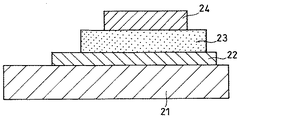
固体電解質中に含まれる遷移金属元素Tの種類を変えて、試験セルを作製した。この試験セルは、図2に示されるように、シリコン基板21、白金集電体層22、固体電解質層23、および白金集電体層24から構成した。
A test cell was prepared by changing the type of the transition metal element T contained in the solid electrolyte. This test cell was composed of a
まず、第1工程で、シリコン基板21の所定の位置に、白金をターゲットとするrfマグネトロンスパッタ法で、厚さ0.5μmの白金集電体層22を形成した。このとき、シリコン基板21としては、表面酸化され、鏡面研磨された、表面粗さが30nm以下のものを用いた。また、白金集電体層22の形成時には、窓(20mm×10mm)を有するメタルマスクを用いた。
First, in a first step, a 0.5 μm-thick platinum
第2工程で、白金集電体層22上に、rfマグネトロンスパッタリングを2時間行うことにより、厚さ1.0μmの固体電解質層23を形成した。このとき、窓の寸法が、15mm×15mmであるメタルマスクを用いた。
In the second step, a 1.0 μm thick
rfマグネトロンスパッタリングにおいては、ターゲットとして、オルトリン酸と、表1に示される遷移金属元素Tとを用いた。スパッタガスとしては、アルゴンを使用した。用いられる装置のチャンバー内圧を2.7Paとし、ガス導入量を10sccmとし、オルトリン酸リチウムターゲットに照射される高周波のパワーを200wとした。また、遷移金属元素Tターゲットに照射される高周波のパワーを制御して、リン原子に対する遷移金属元素Tのモル比が0.2となるようにした。これにより、固体電解質の組成を、すべてLi2.8PT0.2O3.9とした。 In rf magnetron sputtering, orthophosphoric acid and a transition metal element T shown in Table 1 were used as targets. Argon was used as a sputtering gas. The internal pressure of the chamber used was 2.7 Pa, the gas introduction amount was 10 sccm, and the high-frequency power applied to the lithium orthophosphate target was 200 w. Further, the power of the high frequency applied to the transition metal element T target was controlled so that the molar ratio of the transition metal element T to the phosphorus atom was 0.2. Thereby, the compositions of the solid electrolytes were all set to Li 2.8 PT 0.2 O 3.9 .
第3工程で、固体電解質層23の上に、固体電解質層23からはみ出さないように、白金をターゲットとするrfマグネトロンスパッタ法で、厚さ0.5μmの白金集電体層24を形成して、図2に示されるような試験セルを作製した。ここで、白金集電体層を形成するとき、10mm×10mmの寸法の窓を有するメタルマスクを用いた。
In the third step, a 0.5 μm-thick platinum
このようにして得られた試験セルを、それぞれセル1〜17とした。比較として、固体電解質が遷移金属元素Tを含まない試験セルを作製し、これを比較セル1とした。 The test cells thus obtained were called cells 1 to 17, respectively. For comparison, a test cell in which the solid electrolyte did not contain the transition metal element T was prepared, and this was designated as Comparative Cell 1.
次に、これらのセルを用いて、湿潤雰囲気下で2週間保存した後、試験セルのイオン伝導度の変化について調べた。 Next, these cells were stored in a humid atmosphere for two weeks, and then the change in ionic conductivity of the test cells was examined.
まず、作製直後に、試験セルの交流インピーダンスを測定した。
次いで、その試験セルを、相対湿度が50%で、温度が20℃の恒温槽中で2週間保存した。
First, immediately after fabrication, the AC impedance of the test cell was measured.
Then, the test cell was stored for 2 weeks in a thermostat at a relative humidity of 50% and a temperature of 20 ° C.
2週間保存した後、試験セルの交流インピーダンスを測定した。
ここで、上記交流インピーダンスの測定において、平衡電圧をゼロとし、印加される電圧の振幅を±10mVとし、そして用いられる周波数領域を105Hzから0.1Hzまでとした。交流インピーダンス測定の結果から、イオン伝導度を求めた。得られた結果を表1に示す。
After storage for two weeks, the AC impedance of the test cell was measured.
Here, in the measurement of the AC impedance, the equilibrium voltage was set to zero, the amplitude of the applied voltage was set to ± 10 mV, and the frequency range used was set to 10 5 Hz to 0.1 Hz. From the results of the AC impedance measurement, the ionic conductivity was determined. Table 1 shows the obtained results.
ここで、表1において、2週間保存した後のセルのイオン伝導度は、試験セル作製直後のイオン伝導度に対する百分率値として示した。 Here, in Table 1, the ionic conductivity of the cell after storage for 2 weeks was shown as a percentage value with respect to the ionic conductivity immediately after the preparation of the test cell.

表1に示されるように、遷移金属元素Tとリン酸リチウムから作製された固体電解質においては、湿潤雰囲気下で2週間保存しても、イオン伝導度は、大きく変化しなかった。しかし、遷移金属元素Tを含まない従来の固体電解質においては、湿潤雰囲気下での保存により、そのイオン伝導性が大きく低下していた。 As shown in Table 1, in the solid electrolyte prepared from the transition metal element T and lithium phosphate, the ionic conductivity did not significantly change even when stored in a humid atmosphere for two weeks. However, in a conventional solid electrolyte that does not contain the transition metal element T, the ionic conductivity has been greatly reduced by storage in a humid atmosphere.
遷移金属元素Tとしてタングステン(W)を用い、リン原子に対するWのモル比を、表3に示されるように変化させたこと以外、実施例1と同様にして、試験セルを作製した。得られた試験セルを、それぞれ、セル18〜25とした。また、比較として、固体電解質がタングステンを含まない試験セルを作製し、これを比較セル2とした。なお、この比較セル2は、上記比較セル1と同じものである。
これらのセルについて、イオン伝導度の測定を、実施例1と同様にして行った。得られた結果を、表2に示す。
A test cell was fabricated in the same manner as in Example 1, except that tungsten (W) was used as the transition metal element T and the molar ratio of W to phosphorus atoms was changed as shown in Table 3. The obtained test cells were designated as cells 18 to 25, respectively. For comparison, a test cell in which the solid electrolyte did not contain tungsten was prepared, and this was designated as Comparative Cell 2. The comparison cell 2 is the same as the comparison cell 1.
For these cells, the ionic conductivity was measured in the same manner as in Example 1. Table 2 shows the obtained results.
また、これらのセルにおけるイオン伝導度に対する電子伝導度の割合を調べた。
作製直後の試験セルに、平衡電圧から+1.0Vの電圧を印加して、1時間後に流れる電流値を測定した。この得られた結果から、電子伝導度を求めた。試験セル作製直後のイオン伝導度に対する電子伝導度の割合を、電子伝導度/イオン伝導度比率として、表2に示す。
In addition, the ratio of electron conductivity to ionic conductivity in these cells was examined.
A voltage of +1.0 V from the equilibrium voltage was applied to the test cell immediately after fabrication, and the value of the current flowing after one hour was measured. From the obtained result, the electron conductivity was determined. Table 2 shows the ratio of the electron conductivity to the ionic conductivity immediately after the preparation of the test cell as the ratio of electron conductivity / ion conductivity.
表2に示されるように、リンに対するタングステンのモル比が、0.01以上の場合は、湿潤雰囲気下で保存しても、そのイオン伝導度は、大きくは変化しなかった。しかし、リンに対するタングステンのモル比が、0.005の場合には、湿潤雰囲気下での保存により、イオン伝導度が大きく低下した。 As shown in Table 2, when the molar ratio of tungsten to phosphorus was 0.01 or more, the ionic conductivity did not change significantly even when stored in a humid atmosphere. However, when the molar ratio of tungsten to phosphorus was 0.005, ionic conductivity was significantly reduced by storage in a humid atmosphere.
また、リンに対するタングステンのモル比が0.50の場合、電子伝導度比率は、非常に低かった。一方、リンに対するタングステンのモル比が0.50より大きくなると、電子伝導度比率は、高くなった。 When the molar ratio of tungsten to phosphorus was 0.50, the electron conductivity ratio was very low. On the other hand, when the molar ratio of tungsten to phosphorus was greater than 0.50, the electron conductivity ratio increased.
これらの結果より、リン原子に対する遷移金属元素のモル比は、0.01〜0.5であることが好ましい。 From these results, the molar ratio of the transition metal element to the phosphorus atom is preferably 0.01 to 0.5.
固体電解質を形成するときに、遷移金属元素Tの単体の代わりに、表3に示される遷移金属酸化物を用いたこと以外、実施例1と同様にして試験セルを作製した。得られた試験セルを、それぞれセル26〜39とした。また、セル26〜39における固体電解質の組成を表3に示す。 A test cell was produced in the same manner as in Example 1, except that a transition metal oxide shown in Table 3 was used instead of the transition metal element T when forming the solid electrolyte. The obtained test cells were designated as cells 26 to 39, respectively. Table 3 shows the composition of the solid electrolyte in the cells 26 to 39.
また、比較として、固体電解質が遷移金属酸化物を含まない試験セルを作製し、これを比較セル3とした。なお、この比較セル3は、上記比較セル1と同様なものである。 For comparison, a test cell in which the solid electrolyte did not contain a transition metal oxide was prepared, and this was designated as Comparative Cell 3. The comparison cell 3 is similar to the comparison cell 1.
これらのセルについて、実施例1と同様にして、イオン伝導度を求めた。得られた結果を、表3に示す。 The ionic conductivity of these cells was determined in the same manner as in Example 1. Table 3 shows the obtained results.
表3に示されるように、セル26〜39については、湿潤雰囲気下で2週間保存しても、イオン伝導度は、大きくは変化しなかった。一方、遷移金属元素を含まない従来の固体電解質を用いた比較セル3では、湿潤雰囲気下での保存により、そのイオン伝導性が大きく低下した。 As shown in Table 3, for the cells 26 to 39, the ionic conductivity did not significantly change even after storage for 2 weeks in a humid atmosphere. On the other hand, in the comparative cell 3 using the conventional solid electrolyte containing no transition metal element, the ionic conductivity was significantly reduced by storage in a humid atmosphere.
固体電解質を形成する場合に、遷移金属元素Tの単体の代わりに、表4に示されるようなリチウム含有遷移金属酸化物を用いたこと以外、実施例1と同様にして、試験セルを作製した。このようにして得られた試験セルを、それぞれ、セル40〜48とした。また、セル40〜48における固体電解質の組成を表4に示す。 When forming a solid electrolyte, a test cell was produced in the same manner as in Example 1 except that a lithium-containing transition metal oxide as shown in Table 4 was used instead of the simple substance of the transition metal element T. . The test cells thus obtained were referred to as cells 40 to 48, respectively. Table 4 shows the composition of the solid electrolyte in the cells 40 to 48.
また、比較として、固体電解質がリチウム遷移金属酸化物を含まない試験セルを作製し、これを比較セル4とした。なお、この比較セル4は、上記比較セル1と同様なものである。 For comparison, a test cell in which the solid electrolyte did not contain a lithium transition metal oxide was prepared, and this was designated as Comparative Cell 4. The comparison cell 4 is similar to the comparison cell 1.
これらのセルについて、実施例1と同様にして、イオン伝導度を測定した。得られた結果を、表4に示す。 For these cells, the ionic conductivity was measured in the same manner as in Example 1. Table 4 shows the obtained results.
表4に示されるように、本発明の固体電解質においては、湿潤雰囲気下で2週間保存しても、イオン伝導度は、大きく変化しなかった。しかし、遷移金属元素を含まない従来のリン酸リチウムからなる固体電解質においては、湿潤雰囲気下での保存により、イオン伝導性が大きく低下した。 As shown in Table 4, in the solid electrolyte of the present invention, the ionic conductivity did not significantly change even after storage for 2 weeks in a humid atmosphere. However, in a conventional solid electrolyte made of lithium phosphate containing no transition metal element, ionic conductivity was significantly reduced by storage in a humid atmosphere.
固体電解質の形成時に、遷移金属元素Tの単体の代わりに、リチウム含有遷移金属酸化物であるタングステン酸リチウム(Li2WO4)を用いた。リン原子(P)に対するタングステンのモル比を、表5に示されるように変化させたこと以外、実施例1と同様にして、試験セルを作製した。このようにして得られた試験セルを、それぞれ、セル49〜54とした。なお、セル51は、実施例4のセル48と同じものである。 When forming the solid electrolyte, lithium tungstate (Li 2 WO 4 ), which is a lithium-containing transition metal oxide, was used instead of the simple substance of the transition metal element T. A test cell was produced in the same manner as in Example 1, except that the molar ratio of tungsten to phosphorus atoms (P) was changed as shown in Table 5. The test cells thus obtained were referred to as cells 49 to 54, respectively. Note that the cell 51 is the same as the cell 48 of the fourth embodiment.
これらのセルについて、実施例1と同様にして、イオン伝導度を測定した。得られた結果を、表12に示す。 For these cells, the ionic conductivity was measured in the same manner as in Example 1. Table 12 shows the obtained results.
表5に示されるように、湿潤雰囲気下で2週間保存しても、イオン伝導度は、大きく変化しなかった。 As shown in Table 5, the ionic conductivity did not change significantly even after storage for 2 weeks in a humid atmosphere.
次に、表5に示される組成で表される固体電解質とLi金属との反応性を調べるため、図3に示されるような試験セルを作製した。この試験セルは、シリコン基板31、白金集電体層32、固体電解質層33、およびリチウム金属層34から構成した。
Next, a test cell as shown in FIG. 3 was prepared in order to examine the reactivity between the solid electrolyte represented by the composition shown in Table 5 and Li metal. This test cell was composed of a
この試験セルは、図2に示される試験セルの白金集電体層24の代わりに、Li金属層34を、抵抗加熱蒸着法で形成したこと以外、実施例5と同様にして作製した。このようにして得られた試験セルを、それぞれ、セル55〜60とした。
This test cell was produced in the same manner as in Example 5, except that a
得られたセルを、露点温度が−40℃のドライエアー環境下にある部屋に設置した20℃の恒温槽の中に2週間保存した。保存後のこれらのセルのLi金属層の状態を目視で観察した。表6に、その結果を示す。 The obtained cell was stored for 2 weeks in a 20 ° C. constant temperature bath installed in a room under a dry air environment with a dew point temperature of −40 ° C. The state of the Li metal layer of these cells after storage was visually observed. Table 6 shows the results.
表6に示されるように、セル60では、固体電解質とLi金属とが反応し、Li金属層が黒色に変化していた。一方、セル55〜59では、これらのセルをドライエアー環境下で2週間保存したとしても、Li金属層が安定に存在していた。この結果により、リン原子に対するタングステンのモル比が0.01〜1である場合には、固体電解質とLi金属層とが、反応しないことがわかる。 As shown in Table 6, in the cell 60, the solid electrolyte and the Li metal reacted, and the Li metal layer turned black. On the other hand, in the cells 55 to 59, even if these cells were stored in a dry air environment for two weeks, the Li metal layer was stably present. These results show that when the molar ratio of tungsten to phosphorus atoms is 0.01 to 1, the solid electrolyte does not react with the Li metal layer.
以上により、リン原子に対する遷移金属元素Tのモル比が、0.01〜1であればよいことがわかる。 From the above, it is understood that the molar ratio of the transition metal element T to the phosphorus atom may be 0.01 to 1.
リン酸リチウムと遷移金属元素からなる固体電解質を含む全固体電池を作製した。
本実施例においては、図1に示されるような全固体電池を作製した。ここで、第1電極は正極とし、第2電極は負極とした。
An all-solid-state battery including a solid electrolyte composed of lithium phosphate and a transition metal element was manufactured.
In this example, an all-solid-state battery as shown in FIG. 1 was manufactured. Here, the first electrode was a positive electrode, and the second electrode was a negative electrode.
まず、第1工程において、シリコン基板11上に、rfマグネトロンスパッタ法で、白金からなる第1集電体層12を形成した。ここで、シリコン基板11としては、表面酸化され、鏡面研磨された、表面粗さが30nm以下のものを用いた。白金集電体層12を形成するときには、窓(20mm×12mm)を有するメタルマスクを用いた。また、白金集電体層12の厚さを、0.5μmとした。
First, in a first step, a first
第2工程において、コバルト酸リチウム(LiCoO2)をターゲットとして用いるrfマグネトロンスパッタリングを2時間行った。これにより、白金集電体層12上に、正極としてコバルト酸リチウムからなる第1電極層13を形成した。このとき、窓の寸法が10mm×10mmであるメタルマスクを用いた。また、第1電極層13の厚さを、1μmとした。
In the second step, rf magnetron sputtering using lithium cobaltate (LiCoO 2 ) as a target was performed for 2 hours. As a result, the
ここで、rfマグネトロンスパッタリングにおいて、その装置のチャンバー内圧を2.7Paとした。スパッタガスとしてはアルゴンと酸素との混合ガスを使用し、ガス導入量を、それぞれ7.5sccmおよび2.5sccmとした。また、コバルト酸リチウムターゲットに照射される高周波のパワーを、200Wとした。 Here, in rf magnetron sputtering, the chamber internal pressure of the apparatus was set to 2.7 Pa. A mixed gas of argon and oxygen was used as a sputtering gas, and the gas introduction amounts were 7.5 sccm and 2.5 sccm, respectively. The high frequency power applied to the lithium cobaltate target was set to 200 W.
第3工程において、rfマグネトロンスパッタリングを2時間行うことにより、第1電極層13上に、厚さ1μmの固体電解質層14を作製した。このとき、窓の寸法が15mm×15mmであるメタルマスクを用いた。
In the third step, a 1 μm thick
ここで、rfマグネトロンスパッタリングのターゲットとして、オルトリン酸リチウムとタングステン(W)の2種類を用いた。また、スパッタガスとしてはアルゴン(Ar)を使用した。 Here, two kinds of lithium orthophosphate and tungsten (W) were used as targets for rf magnetron sputtering. Argon (Ar) was used as a sputtering gas.
rfマグネトロンスパッタリングにおいて、その装置のチャンバー内圧を2.7Paとし、ガス導入量を10sccmとし、オルトリン酸リチウムターゲットに照射される高周波のパワーを200Wとした。また、リン原子に対するタングステンのモル比が0.2となるように、タングステンターゲットに照射される高周波のパワーを制御した。 In the rf magnetron sputtering, the chamber internal pressure was set to 2.7 Pa, the gas introduction amount was set to 10 sccm, and the high frequency power irradiated to the lithium orthophosphate target was set to 200 W. The high-frequency power applied to the tungsten target was controlled so that the molar ratio of tungsten to phosphorus atoms was 0.2.
第4工程において、固体電解質層14上に、抵抗加熱蒸着法により、負極である第2電極層15を形成した。このとき、窓の寸法が、10mm×10mmであるメタルマスクを用いた。また、第2電極層15の厚さを、0.5μmとした。
In the fourth step, a
最後に、第5工程において、rfマグネトロンスパッタ法により、第2電極層15を完全に覆うように、厚さ1.0μmの第2集電体層16を形成して、試験電池を作製した。ここで、第2集電体層16の形成時、窓の寸法が20mm×12mmであるメタルマスクを用いた。また、形成された第2集電体層16と第1集電体層12とが接触しないようにした。このようにして得られた試験電池を、電池1とした。
Finally, in a fifth step, a 1.0 μm-thick second
比較として、固体電解質がリン酸リチウムのみからなる試験電池を作製し、この電池を比較電池1とした。 For comparison, a test battery in which the solid electrolyte was composed only of lithium phosphate was prepared, and this battery was designated as Comparative Battery 1.
得られた電池1と比較電池1の耐湿性を評価した。
まず、これらの電池を、相対湿度が50%で、温度が20℃の恒温槽中で2週間保存した。次いで、これら電池1および比較電池1の交流インピーダンスを測定した。
The obtained battery 1 and comparative battery 1 were evaluated for moisture resistance.
First, these batteries were stored for 2 weeks in a thermostat at a relative humidity of 50% and a temperature of 20 ° C. Next, the AC impedances of the battery 1 and the comparative battery 1 were measured.
この交流インピーダンスの測定において、平衡電圧をゼロとし、印加される電圧の振幅を±10mVとし、また、用いられる周波数領域を105Hzから0.1Hzまでとした。 In the measurement of the AC impedance, the equilibrium voltage is zero, and the amplitude of the applied voltage and ± 10 mV, also, the frequency region used was from 10 5 Hz to 0.1 Hz.
交流インピーダンス測定から得られた結果から、これらの電池の内部インピーダンスを決定した。得られた内部インピーダンス値を表7に示す。表7において、2週間保存した後の電池の内部インピーダンスは、電池作製直後の内部インピーダンスに対する百分率値として示した。 From the results obtained from the AC impedance measurements, the internal impedance of these cells was determined. Table 7 shows the obtained internal impedance values. In Table 7, the internal impedance of the battery after storage for 2 weeks was shown as a percentage of the internal impedance immediately after the battery was manufactured.
表7に示されるように、本発明の固体電解質を用いた試験電池においては、湿潤雰囲気下で2週間保存したとしても、その内部インピーダンスは大きく変化しなかった。しかし、遷移金属元素を含まない従来の固体電解質を用いた比較電池1においては、内部インピーダンスが大きくなった。これは、湿潤雰囲気下での保存により固体電解質が劣化したためと考えられる。 As shown in Table 7, in the test battery using the solid electrolyte of the present invention, the internal impedance did not significantly change even after being stored in a humid atmosphere for two weeks. However, in the comparative battery 1 using the conventional solid electrolyte containing no transition metal element, the internal impedance was increased. This is presumably because the solid electrolyte was deteriorated by storage in a humid atmosphere.
固体電解質を形成するときに、リチウム含有遷移金属酸化物であるタングステン酸リチウム(Li2WO4)を用い、固体電解質の組成を、Li3.2PW0.1O4.4、Li3.5PW0.25O5.0、またはLi3.66PW0.33O5.32としたこと以外、実施例7と同様にして、試験電池を作製した。このようにして得られた試験電池を、それぞれ、電池2〜4とした。 When forming the solid electrolyte, lithium tungstate (Li 2 WO 4 ) which is a lithium-containing transition metal oxide is used, and the composition of the solid electrolyte is changed to Li 3.2 PW 0.1 O 4.4 , Li 3.5 PW 0.25 O 5.0 , or Li A test battery was prepared in the same manner as in Example 7, except that 3.66 PW 0.33 O 5.32 was used. The test batteries thus obtained were designated as batteries 2 to 4, respectively.
これらの電池2〜4について、湿潤雰囲気下で2週間保存した後の内部インピーダンスを、実施例7と同様にして測定した。得られた結果を表8に示す。 The internal impedance of each of the batteries 2 to 4 after storage in a humid atmosphere for 2 weeks was measured in the same manner as in Example 7. Table 8 shows the obtained results.
表8に示されるように、電池2〜4においては、湿潤雰囲気下で2週間保存したとしても、その内部インピーダンスは、大きく変化しなかった。 As shown in Table 8, in the batteries 2 to 4, the internal impedance did not change significantly even after being stored in a humid atmosphere for two weeks.
以上より、本発明の固体電解質を用いた全固体電池は、湿潤雰囲気下にある場合にも、その電気化学的な特性、例えば、充放電レート特性の劣化を抑制できることがわかる。 From the above, it can be seen that the all-solid-state battery using the solid electrolyte of the present invention can suppress the deterioration of its electrochemical characteristics, for example, the charge and discharge rate characteristics, even in a humid atmosphere.
本発明により、湿潤雰囲気下で使用される場合でも、そのイオン伝導が高く維持される固体電解質を提供することができる。このような固体電解質は、全固体電池の固体電解質として使用することができる。 According to the present invention, it is possible to provide a solid electrolyte that maintains its ionic conductivity high even when used in a humid atmosphere. Such a solid electrolyte can be used as a solid electrolyte of an all-solid battery.
11 基板
12 第1集電体
13 第1電極
14 固体電解質
15 第2電極
16 第2集電体
21、31 シリコン基板
22、24、32 白金集電体層
23、33 固体電解質層
34 リチウム金属層
Claims (7)
LixPTyOz
(ここで、Tは遷移金属元素であり、x=2〜7、y=0.01〜1、z=3.5〜8)
によって表される請求項1記載の固体電解質。 The following formula:
Li x PT y O z
(Where T is a transition metal element, x = 2 to 7, y = 0.01 to 1, z = 3.5 to 8)
The solid electrolyte according to claim 1, represented by:
Priority Applications (1)
| Application Number | Priority Date | Filing Date | Title |
|---|---|---|---|
| JP2004119042A JP3690684B2 (en) | 2003-04-18 | 2004-04-14 | Solid electrolyte and all-solid battery including the same |
Applications Claiming Priority (2)
| Application Number | Priority Date | Filing Date | Title |
|---|---|---|---|
| JP2003113850 | 2003-04-18 | ||
| JP2004119042A JP3690684B2 (en) | 2003-04-18 | 2004-04-14 | Solid electrolyte and all-solid battery including the same |
Publications (2)
| Publication Number | Publication Date |
|---|---|
| JP2004335455A true JP2004335455A (en) | 2004-11-25 |
| JP3690684B2 JP3690684B2 (en) | 2005-08-31 |
Family
ID=33296133
Family Applications (1)
| Application Number | Title | Priority Date | Filing Date |
|---|---|---|---|
| JP2004119042A Expired - Fee Related JP3690684B2 (en) | 2003-04-18 | 2004-04-14 | Solid electrolyte and all-solid battery including the same |
Country Status (6)
| Country | Link |
|---|---|
| US (1) | US7514181B2 (en) |
| EP (1) | EP1630893B1 (en) |
| JP (1) | JP3690684B2 (en) |
| KR (1) | KR100649849B1 (en) |
| CN (1) | CN100337362C (en) |
| WO (1) | WO2004093236A1 (en) |
Cited By (10)
| Publication number | Priority date | Publication date | Assignee | Title |
|---|---|---|---|---|
| WO2006073104A1 (en) * | 2005-01-06 | 2006-07-13 | Matsushita Electric Industrial Co., Ltd. | Positive electrode for lithium ion battery and lithium ion battery using same |
| JP2007103129A (en) * | 2005-10-03 | 2007-04-19 | Geomatec Co Ltd | Thin-film solid secondary battery and method for producing thin-film solid secondary battery |
| JP2008532238A (en) * | 2005-03-03 | 2008-08-14 | コーニンクレッカ フィリップス エレクトロニクス エヌ ヴィ | Method for producing electrochemical energy source, electrochemical energy source obtained by the method, and electronic device |
| US7632607B2 (en) | 2004-10-21 | 2009-12-15 | Panasonic Corporation | Negative electrode for battery and battery using the same |
| EP2189064A1 (en) | 2004-11-19 | 2010-05-26 | Meiji Dairies Corporation | Cream and processed cream products having excellent flavor and physical properties thereof |
| JP4923261B2 (en) * | 2005-01-26 | 2012-04-25 | 国立大学法人京都大学 | Lithium battery and manufacturing method thereof |
| DE112012000513T5 (en) | 2011-01-19 | 2013-10-24 | Sumitomo Electric Industries, Ltd. | Non-aqueous electrolyte battery |
| WO2013175992A1 (en) * | 2012-05-24 | 2013-11-28 | 株式会社 村田製作所 | All-solid-state battery |
| JP2023521736A (en) * | 2020-07-23 | 2023-05-25 | エルジー エナジー ソリューション リミテッド | All-solid-state battery including thin-film current collector and manufacturing method thereof |
| JP2024537602A (en) * | 2022-09-13 | 2024-10-16 | ベイス カンパニー,リミテッド | Sintering aid for solid electrolyte for all-solid-state battery and solid electrolyte containing same |
Families Citing this family (21)
| Publication number | Priority date | Publication date | Assignee | Title |
|---|---|---|---|---|
| DE102006018233A1 (en) * | 2005-07-14 | 2007-10-25 | Elsper, Rüdiger, Dr. | Manufacture of inorganic solid state cation conductor involves removing low valent heavy metal portion from dispersion of starting material of metal mixed oxide or salt in presence of monovalent cations and/or disproportionated |
| DE102006025663A1 (en) * | 2005-07-14 | 2007-12-06 | Elsper, Rüdiger, Dr. | Manufacture of inorganic solid state cation conductor involves removing low valent heavy metal portion from dispersion of starting material of metal mixed oxide or salt in presence of monovalent cations and/or disproportionated |
| US8323832B2 (en) * | 2005-08-08 | 2012-12-04 | A123 Systems, Inc. | Nanoscale ion storage materials |
| US8158090B2 (en) * | 2005-08-08 | 2012-04-17 | A123 Systems, Inc. | Amorphous and partially amorphous nanoscale ion storage materials |
| CN101903560B (en) * | 2007-12-21 | 2014-08-06 | 无穷动力解决方案股份有限公司 | Method for sputter targets for electrolyte films |
| JP5444771B2 (en) * | 2009-03-10 | 2014-03-19 | ソニー株式会社 | Solid electrolyte battery and method for producing solid electrolyte battery |
| CN102206802B (en) * | 2010-03-29 | 2012-12-19 | 苏州晶纯新材料有限公司 | All-solid-state film lithium ion battery related target material and manufacturing method thereof |
| US9577285B2 (en) | 2010-10-15 | 2017-02-21 | Samsung Sdi Co., Ltd. | Solid electrolyte, method for preparing same, and rechargeable lithium battery comprising solid electrolyte and solid electrolyte particles |
| CN103443864B (en) * | 2011-03-23 | 2016-01-13 | 雅马哈发动机株式会社 | Conductive composition, dispersion system, method for producing conductive composition, and solid electrolyte battery |
| CN102285790B (en) * | 2011-06-22 | 2012-08-08 | 苏州晶纯新材料有限公司 | Lithium iron phosphate target materials and preparation method thereof |
| CN102249661B (en) * | 2011-06-22 | 2012-08-08 | 苏州晶纯新材料有限公司 | Lithium phosphate target and preparation method thereof |
| CN102925978B (en) * | 2012-11-07 | 2015-01-14 | 深圳华粤宝电池有限公司 | Lithium niobtate crystal and solid electrolyte and preparation methods and application thereof |
| US10263279B2 (en) * | 2012-12-14 | 2019-04-16 | Sila Nanotechnologies Inc. | Electrodes for energy storage devices with solid electrolytes and methods of fabricating the same |
| CN103904360B (en) * | 2012-12-27 | 2016-08-03 | 华为技术有限公司 | A kind of solid electrolyte and preparation method thereof and solid lithium battery |
| WO2018181827A1 (en) * | 2017-03-30 | 2018-10-04 | Tdk株式会社 | Solid electrolyte and all-solid lithium-ion secondary battery |
| CN111977626B (en) | 2019-05-24 | 2024-11-01 | 三星电子株式会社 | Solid conductor, method for preparing the same, solid electrolyte comprising the solid conductor, and electrochemical device comprising the solid conductor |
| US11807543B2 (en) | 2019-08-02 | 2023-11-07 | Ut-Battelle, Llc | Ionically conductive powders and films, and methods of preparation |
| JP6890640B2 (en) * | 2019-08-30 | 2021-06-18 | 昭和電工株式会社 | Lithium ion conductive oxide |
| KR20230013093A (en) * | 2020-06-10 | 2023-01-26 | 쇼와 덴코 가부시키가이샤 | Solid electrolyte material, solid electrolyte, method for producing solid electrolyte and all-solid-state battery |
| US11575152B2 (en) | 2020-06-29 | 2023-02-07 | Samsung Electronics Co., Ltd. | Oxide, preparation method thereof, solid electrolyte including the oxide, and electrochemical device including the oxide |
| EP4001213A1 (en) | 2020-11-13 | 2022-05-25 | Samsung Electronics Co., Ltd. | Oxide, method of preparing the same, solid electrolyte including the oxide, and electrochemical device including the oxide |
Citations (10)
| Publication number | Priority date | Publication date | Assignee | Title |
|---|---|---|---|---|
| JPH02225310A (en) * | 1989-02-23 | 1990-09-07 | Matsushita Electric Ind Co Ltd | Solid electrolyte and its manufacturing method |
| JPH0329206A (en) * | 1989-03-09 | 1991-02-07 | Japan Synthetic Rubber Co Ltd | Lithium ion conductive solid electrolyte and its manufacture |
| JPH03246868A (en) * | 1990-02-26 | 1991-11-05 | Nippon Telegr & Teleph Corp <Ntt> | Lithium ion conductive solid electrolyte material |
| JPH04162306A (en) * | 1990-10-25 | 1992-06-05 | Nippon Telegr & Teleph Corp <Ntt> | Lithium ion conductive solid electrolytic sheet |
| JPH05299101A (en) * | 1992-02-18 | 1993-11-12 | Sanyo Electric Co Ltd | Solid electrolyte and lithium battery using the same |
| JPH117942A (en) * | 1997-06-19 | 1999-01-12 | Matsushita Electric Ind Co Ltd | All-solid lithium battery |
| JP2000109360A (en) * | 1998-10-02 | 2000-04-18 | Agency Of Ind Science & Technol | Manufacturing method of lithium titanate sintered body |
| JP2000200621A (en) * | 1998-12-28 | 2000-07-18 | Central Res Inst Of Electric Power Ind | All-solid-state secondary battery and manufacturing method thereof |
| JP2001126758A (en) * | 1999-10-28 | 2001-05-11 | Kyocera Corp | Lithium battery |
| JP2002042862A (en) * | 2000-07-26 | 2002-02-08 | Kyocera Corp | Lithium battery |
Family Cites Families (6)
| Publication number | Priority date | Publication date | Assignee | Title |
|---|---|---|---|---|
| US5338625A (en) | 1992-07-29 | 1994-08-16 | Martin Marietta Energy Systems, Inc. | Thin film battery and method for making same |
| JP3906944B2 (en) * | 1997-05-12 | 2007-04-18 | 株式会社ジーエス・ユアサコーポレーション | Non-aqueous solid electrolyte battery |
| WO2000060679A1 (en) * | 1999-04-06 | 2000-10-12 | Sony Corporation | Method for manufacturing active material of positive plate and method for manufacturing nonaqueous electrolyte secondary cell |
| CA2320661A1 (en) | 2000-09-26 | 2002-03-26 | Hydro-Quebec | New process for synthesizing limpo4 materials with olivine structure |
| CN1392623A (en) * | 2001-06-15 | 2003-01-22 | 未来科技研究院有限公司 | Lithium phosphorus oxygen nitrogen sulfur compound electrolyte thin film |
| JP2003346896A (en) * | 2002-05-30 | 2003-12-05 | Fujitsu Ltd | Method for producing solid electrolyte, solid electrolyte, and lithium battery |
-
2004
- 2004-04-14 JP JP2004119042A patent/JP3690684B2/en not_active Expired - Fee Related
- 2004-04-15 WO PCT/JP2004/005424 patent/WO2004093236A1/en not_active Ceased
- 2004-04-15 CN CNB2004800045115A patent/CN100337362C/en not_active Expired - Fee Related
- 2004-04-15 KR KR1020057017726A patent/KR100649849B1/en not_active Expired - Fee Related
- 2004-04-15 US US10/551,935 patent/US7514181B2/en not_active Expired - Lifetime
- 2004-04-15 EP EP04727754A patent/EP1630893B1/en not_active Expired - Lifetime
Patent Citations (10)
| Publication number | Priority date | Publication date | Assignee | Title |
|---|---|---|---|---|
| JPH02225310A (en) * | 1989-02-23 | 1990-09-07 | Matsushita Electric Ind Co Ltd | Solid electrolyte and its manufacturing method |
| JPH0329206A (en) * | 1989-03-09 | 1991-02-07 | Japan Synthetic Rubber Co Ltd | Lithium ion conductive solid electrolyte and its manufacture |
| JPH03246868A (en) * | 1990-02-26 | 1991-11-05 | Nippon Telegr & Teleph Corp <Ntt> | Lithium ion conductive solid electrolyte material |
| JPH04162306A (en) * | 1990-10-25 | 1992-06-05 | Nippon Telegr & Teleph Corp <Ntt> | Lithium ion conductive solid electrolytic sheet |
| JPH05299101A (en) * | 1992-02-18 | 1993-11-12 | Sanyo Electric Co Ltd | Solid electrolyte and lithium battery using the same |
| JPH117942A (en) * | 1997-06-19 | 1999-01-12 | Matsushita Electric Ind Co Ltd | All-solid lithium battery |
| JP2000109360A (en) * | 1998-10-02 | 2000-04-18 | Agency Of Ind Science & Technol | Manufacturing method of lithium titanate sintered body |
| JP2000200621A (en) * | 1998-12-28 | 2000-07-18 | Central Res Inst Of Electric Power Ind | All-solid-state secondary battery and manufacturing method thereof |
| JP2001126758A (en) * | 1999-10-28 | 2001-05-11 | Kyocera Corp | Lithium battery |
| JP2002042862A (en) * | 2000-07-26 | 2002-02-08 | Kyocera Corp | Lithium battery |
Cited By (14)
| Publication number | Priority date | Publication date | Assignee | Title |
|---|---|---|---|---|
| US7632607B2 (en) | 2004-10-21 | 2009-12-15 | Panasonic Corporation | Negative electrode for battery and battery using the same |
| EP2189064A1 (en) | 2004-11-19 | 2010-05-26 | Meiji Dairies Corporation | Cream and processed cream products having excellent flavor and physical properties thereof |
| JPWO2006073104A1 (en) * | 2005-01-06 | 2008-06-12 | 松下電器産業株式会社 | Lithium ion battery positive electrode and lithium ion battery using the same |
| WO2006073104A1 (en) * | 2005-01-06 | 2006-07-13 | Matsushita Electric Industrial Co., Ltd. | Positive electrode for lithium ion battery and lithium ion battery using same |
| CN100490219C (en) * | 2005-01-06 | 2009-05-20 | 松下电器产业株式会社 | Positive electrode for lithium ion battery and lithium ion battery using same |
| US7638236B2 (en) | 2005-01-06 | 2009-12-29 | Panasonic Corporation | Positive electrode for lithium ion battery and lithium ion battery using same |
| JP4923261B2 (en) * | 2005-01-26 | 2012-04-25 | 国立大学法人京都大学 | Lithium battery and manufacturing method thereof |
| JP2008532238A (en) * | 2005-03-03 | 2008-08-14 | コーニンクレッカ フィリップス エレクトロニクス エヌ ヴィ | Method for producing electrochemical energy source, electrochemical energy source obtained by the method, and electronic device |
| JP2007103129A (en) * | 2005-10-03 | 2007-04-19 | Geomatec Co Ltd | Thin-film solid secondary battery and method for producing thin-film solid secondary battery |
| DE112012000513T5 (en) | 2011-01-19 | 2013-10-24 | Sumitomo Electric Industries, Ltd. | Non-aqueous electrolyte battery |
| WO2013175992A1 (en) * | 2012-05-24 | 2013-11-28 | 株式会社 村田製作所 | All-solid-state battery |
| JP2023521736A (en) * | 2020-07-23 | 2023-05-25 | エルジー エナジー ソリューション リミテッド | All-solid-state battery including thin-film current collector and manufacturing method thereof |
| JP7584812B2 (en) | 2020-07-23 | 2024-11-18 | エルジー エナジー ソリューション リミテッド | All-solid-state battery including thin-film current collector and method for manufacturing same |
| JP2024537602A (en) * | 2022-09-13 | 2024-10-16 | ベイス カンパニー,リミテッド | Sintering aid for solid electrolyte for all-solid-state battery and solid electrolyte containing same |
Also Published As
| Publication number | Publication date |
|---|---|
| WO2004093236A1 (en) | 2004-10-28 |
| EP1630893A4 (en) | 2007-07-18 |
| US7514181B2 (en) | 2009-04-07 |
| EP1630893A1 (en) | 2006-03-01 |
| KR20050118200A (en) | 2005-12-15 |
| KR100649849B1 (en) | 2006-11-28 |
| EP1630893B1 (en) | 2012-04-04 |
| JP3690684B2 (en) | 2005-08-31 |
| CN100337362C (en) | 2007-09-12 |
| US20060216611A1 (en) | 2006-09-28 |
| CN1751409A (en) | 2006-03-22 |
Similar Documents
| Publication | Publication Date | Title |
|---|---|---|
| JP3690684B2 (en) | Solid electrolyte and all-solid battery including the same | |
| US7217478B2 (en) | Solid electrolyte and all-solid battery using the same | |
| JP5316809B2 (en) | Lithium battery and manufacturing method thereof | |
| JP3677508B2 (en) | Solid electrolyte and all solid state battery using the same | |
| US20110281167A1 (en) | Thin film solid state lithium ion secondary battery and method of manufacturing the same | |
| US9991555B2 (en) | Solid electrolyte for a microbattery | |
| JP3677509B2 (en) | Solid electrolyte and all solid state battery using the same | |
| WO2010090125A1 (en) | Solid state thin film lithium ion secondary battery and manufacturing method therefor | |
| JP2011511399A (en) | Thin film electrolytes for thin film batteries | |
| CN100413138C (en) | Solid electrolyte and all-solid-state battery using the same | |
| KR20070091182A (en) | Positive electrode for lithium ion battery and lithium ion battery using same | |
| JP2009199920A (en) | Lithium battery | |
| JP5217455B2 (en) | Lithium battery and method for producing lithium battery | |
| JP2006156284A (en) | Lithium ion conductor and secondary battery using the same | |
| US20110070503A1 (en) | Solid Electrolyte, Fabrication Method Thereof and Thin Film Battery Comprising the Same | |
| JP2006120437A (en) | Solid electrolyte battery | |
| JP2011086555A (en) | Nonaqueous electrolyte battery, and manufacturing method thereof | |
| JP4695375B2 (en) | Solid electrolyte and all-solid battery including the same | |
| JP4522078B2 (en) | Solid electrolyte for all solid state battery and all solid state battery using the same | |
| JP2005108638A (en) | Lithium ion conductor | |
| JP2009218125A (en) | Lithium battery | |
| JP2006120337A (en) | Battery negative electrode and battery using the same | |
| JP2015053175A (en) | All-solid state battery |
Legal Events
| Date | Code | Title | Description |
|---|---|---|---|
| A521 | Request for written amendment filed |
Free format text: JAPANESE INTERMEDIATE CODE: A523 Effective date: 20040901 |
|
| A621 | Written request for application examination |
Free format text: JAPANESE INTERMEDIATE CODE: A621 Effective date: 20040901 |
|
| A871 | Explanation of circumstances concerning accelerated examination |
Free format text: JAPANESE INTERMEDIATE CODE: A871 Effective date: 20050228 |
|
| A975 | Report on accelerated examination |
Free format text: JAPANESE INTERMEDIATE CODE: A971005 Effective date: 20050316 |
|
| A131 | Notification of reasons for refusal |
Free format text: JAPANESE INTERMEDIATE CODE: A131 Effective date: 20050324 |
|
| A521 | Request for written amendment filed |
Free format text: JAPANESE INTERMEDIATE CODE: A523 Effective date: 20050510 |
|
| TRDD | Decision of grant or rejection written | ||
| A01 | Written decision to grant a patent or to grant a registration (utility model) |
Free format text: JAPANESE INTERMEDIATE CODE: A01 Effective date: 20050602 |
|
| A61 | First payment of annual fees (during grant procedure) |
Free format text: JAPANESE INTERMEDIATE CODE: A61 Effective date: 20050609 |
|
| R150 | Certificate of patent or registration of utility model |
Ref document number: 3690684 Country of ref document: JP Free format text: JAPANESE INTERMEDIATE CODE: R150 Free format text: JAPANESE INTERMEDIATE CODE: R150 |
|
| FPAY | Renewal fee payment (event date is renewal date of database) |
Free format text: PAYMENT UNTIL: 20080624 Year of fee payment: 3 |
|
| FPAY | Renewal fee payment (event date is renewal date of database) |
Free format text: PAYMENT UNTIL: 20090624 Year of fee payment: 4 |
|
| FPAY | Renewal fee payment (event date is renewal date of database) |
Free format text: PAYMENT UNTIL: 20100624 Year of fee payment: 5 |
|
| FPAY | Renewal fee payment (event date is renewal date of database) |
Free format text: PAYMENT UNTIL: 20100624 Year of fee payment: 5 |
|
| FPAY | Renewal fee payment (event date is renewal date of database) |
Free format text: PAYMENT UNTIL: 20110624 Year of fee payment: 6 |
|
| FPAY | Renewal fee payment (event date is renewal date of database) |
Free format text: PAYMENT UNTIL: 20120624 Year of fee payment: 7 |
|
| FPAY | Renewal fee payment (event date is renewal date of database) |
Free format text: PAYMENT UNTIL: 20120624 Year of fee payment: 7 |
|
| FPAY | Renewal fee payment (event date is renewal date of database) |
Free format text: PAYMENT UNTIL: 20130624 Year of fee payment: 8 |
|
| LAPS | Cancellation because of no payment of annual fees |