JP2004340468A - Integrated multiplate heat exchanger - Google Patents
Integrated multiplate heat exchanger Download PDFInfo
- Publication number
- JP2004340468A JP2004340468A JP2003136896A JP2003136896A JP2004340468A JP 2004340468 A JP2004340468 A JP 2004340468A JP 2003136896 A JP2003136896 A JP 2003136896A JP 2003136896 A JP2003136896 A JP 2003136896A JP 2004340468 A JP2004340468 A JP 2004340468A
- Authority
- JP
- Japan
- Prior art keywords
- absorber
- core
- evaporator
- heat exchanger
- casing
- Prior art date
- Legal status (The legal status is an assumption and is not a legal conclusion. Google has not performed a legal analysis and makes no representation as to the accuracy of the status listed.)
- Pending
Links
- 239000006096 absorbing agent Substances 0.000 claims abstract description 64
- 239000007788 liquid Substances 0.000 claims abstract description 28
- 238000010521 absorption reaction Methods 0.000 claims abstract description 21
- 230000002745 absorbent Effects 0.000 claims description 20
- 239000002250 absorbent Substances 0.000 claims description 20
- 238000005192 partition Methods 0.000 claims description 9
- 238000000926 separation method Methods 0.000 abstract 1
- 238000000638 solvent extraction Methods 0.000 abstract 1
- 239000003507 refrigerant Substances 0.000 description 16
- 239000006185 dispersion Substances 0.000 description 8
- 239000007921 spray Substances 0.000 description 8
- 239000000498 cooling water Substances 0.000 description 6
- 239000012267 brine Substances 0.000 description 5
- HPALAKNZSZLMCH-UHFFFAOYSA-M sodium;chloride;hydrate Chemical compound O.[Na+].[Cl-] HPALAKNZSZLMCH-UHFFFAOYSA-M 0.000 description 5
- 239000000243 solution Substances 0.000 description 3
- AMXOYNBUYSYVKV-UHFFFAOYSA-M lithium bromide Chemical compound [Li+].[Br-] AMXOYNBUYSYVKV-UHFFFAOYSA-M 0.000 description 2
- 238000005507 spraying Methods 0.000 description 2
- 230000000694 effects Effects 0.000 description 1
- 238000010030 laminating Methods 0.000 description 1
- 230000008929 regeneration Effects 0.000 description 1
- 238000011069 regeneration method Methods 0.000 description 1
- XLYOFNOQVPJJNP-UHFFFAOYSA-N water Substances O XLYOFNOQVPJJNP-UHFFFAOYSA-N 0.000 description 1
Images
Classifications
-
- Y—GENERAL TAGGING OF NEW TECHNOLOGICAL DEVELOPMENTS; GENERAL TAGGING OF CROSS-SECTIONAL TECHNOLOGIES SPANNING OVER SEVERAL SECTIONS OF THE IPC; TECHNICAL SUBJECTS COVERED BY FORMER USPC CROSS-REFERENCE ART COLLECTIONS [XRACs] AND DIGESTS
- Y02—TECHNOLOGIES OR APPLICATIONS FOR MITIGATION OR ADAPTATION AGAINST CLIMATE CHANGE
- Y02A—TECHNOLOGIES FOR ADAPTATION TO CLIMATE CHANGE
- Y02A30/00—Adapting or protecting infrastructure or their operation
- Y02A30/27—Relating to heating, ventilation or air conditioning [HVAC] technologies
-
- Y—GENERAL TAGGING OF NEW TECHNOLOGICAL DEVELOPMENTS; GENERAL TAGGING OF CROSS-SECTIONAL TECHNOLOGIES SPANNING OVER SEVERAL SECTIONS OF THE IPC; TECHNICAL SUBJECTS COVERED BY FORMER USPC CROSS-REFERENCE ART COLLECTIONS [XRACs] AND DIGESTS
- Y02—TECHNOLOGIES OR APPLICATIONS FOR MITIGATION OR ADAPTATION AGAINST CLIMATE CHANGE
- Y02B—CLIMATE CHANGE MITIGATION TECHNOLOGIES RELATED TO BUILDINGS, e.g. HOUSING, HOUSE APPLIANCES OR RELATED END-USER APPLICATIONS
- Y02B30/00—Energy efficient heating, ventilation or air conditioning [HVAC]
- Y02B30/62—Absorption based systems
Landscapes
- Sorption Type Refrigeration Machines (AREA)
Abstract
Description
【0001】
【発明の属する技術分野】
本願発明は、吸収冷凍機において吸収器と蒸発器とを一体に組合せた多板式の熱交換器に関する。
【0002】
【従来の技術】
この種の一体型多板式熱交換器については、既に同じ出願人が先に出願した例がある(例えば、特許文献1参照)。
【0003】
【特許文献1】
特開平10−232066号公報
【0004】
同特許文献1に開示されたものは、凹凸加工を施した2枚のプレートを互いに重ね合わせたエレメントを複数重ね合わせて形成された互いに別体の蒸発器コアと吸収器コアがさらに互いに重ね合わされ、両者間に仕切り板を介在させて1つのケーシング内に収容され一体に組み付けられた一体型多板式熱交換器である。
【0005】
吸収器コアを構成する各エレメントには、上方に位置する吸収液噴霧ノズルから濃吸収液が満遍なく散布され、蒸発器で蒸発した冷媒蒸気が上方の共通空間を経て吸収器側に移動して各吸収器エレメントに付着した濃吸収液に吸収され、この時発生する吸収熱はエレメント内部を流れる冷却水により除かれる。
【0006】
【発明が解決しようとする課題】
しかし、濃吸収液が満遍なく散布され各吸収器エレメントのうち、蒸発器側で発生する冷媒蒸気はその多くが蒸発器に近い吸収器エレメントにおいて吸収液に吸収される傾向にある。
【0007】
したがって、蒸発器から遠い吸収器エレメントが有効に機能せず、吸収器コア全体での吸収性能が十分発揮されない。
【0008】
本願発明は、斯かる点に鑑みなされたもので、その目的とする処は、吸収器コア全体での吸収性能が十分発揮される簡単な構造の一体型多板式熱交換器を供する点にある。
【0009】
【課題を解決するための手段及び作用効果】
上記目的を達成するために、本請求項1記載の発明は、吸収器と蒸発器が組合された一体型多板式熱交換器であって、両面に凹凸加工を施した2枚のプレートを互いに重ね合わせてエレメントを形成し同エレメントを複数重ね合せて吸収器コアと蒸発器コアがそれぞれ構成され、1ケーシング内に前記吸収器コアと前記蒸発器コアが左右に収容され、同ケーシングの上方空間を除く空間が仕切部材により吸収器側と蒸発器側とに仕切られ、前記吸収器コアの前記蒸発器コアに対して遠い部分ほどより濃度の高い吸収液が散布されることを特徴とする一体型多板式熱交換器とした。
【0010】
蒸発器コアにおいて発生する冷媒蒸気は、吸収器コアの蒸発器コアに近い部分ほど吸収液に吸収され易く遠い部分ほど吸収され難い傾向にあるので、吸収器コアの蒸発器コアに対して遠い部分ほどより濃度の高い吸収液が散布される構成とすることで、吸収器コアの冷媒蒸気が吸収され難い蒸発器コアから遠い部分に吸収能力のある濃度の高い吸収液が散布されて機能を確保し、吸収器コア全体で冷媒蒸気を効率良く吸収し吸収器としての吸収性能を向上させることができる。
【0011】
請求項2記載の発明は、請求項1記載の一体型多板式熱交換器において、複数の吸収器エレメントが左右方向に重ね合わされる姿勢で前記吸収器コアが前記ケーシングに収容され、前記蒸発器コアに対して遠い吸収器エレメントほどより濃度の高い吸収液が散布されることを特徴とする。
【0012】
吸収器コアと蒸発器コアはケーシング内の左右に収容され、吸収器エレメントが左右方向に重ね合わされるので、吸収器エレメントは蒸発器コアに近いものから離れる方向に順に配列される構造となり、蒸発器コアに対して遠い吸収器エレメントほどより濃度の高い吸収液が散布されることで、吸収器コア全体で略均等に冷媒蒸気を効率良く吸収し吸収器としての吸収性能を向上させることができる。
【0013】
請求項3記載の発明は、請求項1記載の一体型多板式熱交換器において、前記吸収器コアの前記蒸発器コアに対して遠い部分には再生器から回送されてきた濃吸収液が散布され、前記蒸発器コアに対してより近い部分には吸収器側ケーシング底部に溜まった吸収液が直接散布されることを特徴とする。
【0014】
吸収器コアの前記蒸発器コアに対して遠い部分には濃吸収液が散布され、近い部分には稀吸収液が散布される構成が、吸収冷凍機の通常の機器だけで容易にできるので、構造が簡単でコストも抑えることができる。
【0015】
【発明の実施の形態】
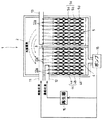
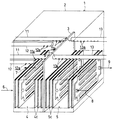
以下本発明に係る一実施の形態について図1および図2に基づき説明する。
本実施の形態に係る吸収器と蒸発器の組合せ一体型多板式熱交換器1は、ケーシング2内の仕切板3に仕切られた左右に吸収器コア4と蒸発器コア5が収容されている。
【0016】
仕切板3はケーシング2内の上方空間を除く空間を仕切っていて吸収器コア4と蒸発器コア5の上方空間は連通していて蒸発器側で発生した冷媒蒸気が吸収器側に移動することができる。
【0017】
吸収器コア4と蒸発器コア5は、いずれも両面に凹凸加工を施した2枚のプレート4a,4b,5a,5bを互いに重ね合わせて吸収器エレメント4c,蒸発器エレメント5cを形成し同吸収器エレメント4c,蒸発器エレメント5cをそれぞれ複数重ね合せて多板式熱交換器のコアとして構成されている。
【0018】
同吸収器エレメント4cの内側の内空間4dには冷却水供給管6から冷却水が供給され、内部を流れて冷却水排出管7から排出され、蒸発器エレメント5cの内側の内空間5dにはブライン供給管8からブラインが供給され、内部を流れてブライン排出管9から排出される。
【0019】
吸収器コア4の上方には、上下1対の吸収液散布管11,12が前後に2対側方からケーシング2を貫通して配設されている。
上側の吸収液散布管11は仕切板3近くまで延出され、下方の各吸収器エレメント4cに向けて開口した供給口11aが蒸発器コア5に近い吸収器エレメント4cから過半数の吸収器エレメント4cに対応して形成されている。
【0020】
下側の吸収液散布管12は上側の吸収液散布管11の半分弱しか延出しておらず、上側の吸収液散布管11の供給口11aが対応していない蒸発器コア5から遠い吸収器エレメント4cに対応して供給口12aが形成されている。
【0021】
他方蒸発器コア5の上方には、前後2本の冷媒液散布管13が側方からケーシング2を貫通して仕切板3近くまで延出され、下方の各蒸発器エレメント5cに向けて開口した供給口13aが全ての蒸発器エレメント5cに対応して形成されて冷媒液(例えば、水)を蒸発器エレメント5cに散布する。
【0022】
ケーシング2の吸収器コア4の下方には冷媒蒸気を吸収して濃度が薄められた稀吸収液(例えば、LiBr水溶液)が溜まり、この稀吸収液をポンプ15が吸入し、再生器16に回送し、再生器16で濃度を回復した濃吸収液が吸収液散布管12に送られる。
【0023】
またポンプ15から吐出した稀吸収液は、再生器16までの途中にある分岐路により分岐して流れ、一方が再生器16に流れ、他方に流れた稀吸収液は直接吸収液散布管11に送られる。
【0024】
したがって吸収液散布管11は供給口11aから稀吸収液を蒸発器コア5に近い方の吸収器エレメント4cに散布し、吸収液散布管12は供給口12aから濃吸収液を蒸発器コア5に遠い方の吸収器エレメント4cに散布することになる。
【0025】
蒸発器コア5に対して近い吸収器エレメント4cは稀吸収液であっても冷媒蒸気を容易に吸収し、蒸発器コア5に対して遠い吸収器エレメント4cは冷媒蒸気を吸収し難い位置にあるが、濃度の高い吸収液が散布されることで有効に冷媒蒸気を吸収することができ、吸収器コア4全体で冷媒蒸気を効率良く吸収し吸収器としての吸収性能を向上させることができる。
【0026】
再生器の再生性能を高くする必要はなく従前の再生器を用いることができ、ポンプ15から再生器16までの途中に分岐路を設けて吸収液散布管11に稀吸収液を供給する流路を新たに設ける簡単な構造である。
【0027】
なお吸収液散布管11,12および冷媒液散布管13の供給口11a,12a,13aにメッシュを被せるようにすると、管内の液圧による液はねや供給口の位置による散布量の不均一を防止することができる。
【図面の簡単な説明】
【図1】本願発明の一実施の形態に係る吸収器と蒸発器の組合せ一体型多板式熱交換器の断面図である。
【図2】同一体型多板式熱交換器のケーシングを透過した斜視図である。
【符号の説明】
1…一体型多板式熱交換器、2…ケーシング、3…仕切板、4…吸収器コア、4a,4b…プレート、4c…吸収器エレメント、5…蒸発器コア、5a,5b…プレート、5c…蒸発器エレメント、6…冷却水供給管、7…冷却水排出管、8…ブライン供給管、9…ブライン排出管、11…吸収液散布管、12…吸収液散布管、13…冷媒液散布管、15…ポンプ、16…再生器。[0001]
TECHNICAL FIELD OF THE INVENTION
The present invention relates to a multi-plate heat exchanger in which an absorber and an evaporator are integrally combined in an absorption refrigerator.
[0002]
[Prior art]
An example of this type of integrated multi-plate heat exchanger has already been filed by the same applicant earlier (for example, see Patent Document 1).
[0003]
[Patent Document 1]
JP-A-10-23266
The
[0005]
In each element constituting the absorber core, the concentrated absorption liquid is evenly sprayed from the absorption liquid spray nozzle located above, and the refrigerant vapor evaporated by the evaporator moves to the absorber side through the upper common space to each of the elements. Absorbed heat is absorbed by the concentrated absorbent adhering to the absorber element, and the absorption heat generated at this time is removed by cooling water flowing inside the element.
[0006]
[Problems to be solved by the invention]
However, most of the refrigerant vapor generated on the evaporator side among the absorber elements with the concentrated absorbent scattered uniformly tends to be absorbed by the absorbent liquid in the absorber element close to the evaporator.
[0007]
Therefore, the absorber element far from the evaporator does not function effectively, and the absorption performance of the entire absorber core is not sufficiently exhibited.
[0008]
The present invention has been made in view of such a point, and an object thereof is to provide an integrated multi-plate heat exchanger having a simple structure in which the absorption performance of the entire absorber core is sufficiently exhibited. .
[0009]
Means for Solving the Problems and Functions and Effects
In order to achieve the above object, the invention according to
[0010]
Refrigerant vapor generated in the evaporator core is more likely to be absorbed by the absorbing liquid as the part of the absorber core is closer to the evaporator core and is less likely to be absorbed as the part is farther away. The absorption liquid with higher concentration is sprayed to the part far from the evaporator core where the refrigerant vapor of the absorber core is hard to be absorbed, so that the function is ensured. In addition, the refrigerant vapor can be efficiently absorbed by the entire absorber core, and the absorption performance of the absorber can be improved.
[0011]
According to a second aspect of the present invention, in the integrated multi-plate heat exchanger according to the first aspect, the absorber core is accommodated in the casing in a posture in which a plurality of absorber elements are superimposed in the left-right direction, and the evaporator is provided. Absorber elements farther from the core are sprayed with a higher concentration of absorbent.
[0012]
The absorber core and the evaporator core are housed on the left and right inside the casing, and the absorber elements are superimposed in the left-right direction, so that the absorber elements are arranged in order in a direction away from the one near the evaporator core, and As the absorber element is farther away from the absorber core, the absorption liquid having a higher concentration is sprayed, so that the refrigerant vapor can be efficiently absorbed substantially uniformly throughout the absorber core and the absorption performance as the absorber can be improved. .
[0013]
According to a third aspect of the present invention, in the integrated multi-plate heat exchanger according to the first aspect, a concentrated absorption liquid sent from a regenerator is sprayed on a portion of the absorber core far from the evaporator core. The absorption liquid collected at the bottom of the absorber-side casing is directly sprayed to a portion closer to the evaporator core.
[0014]
The structure in which the concentrated absorbent is sprayed on the portion of the absorber core far from the evaporator core and the diluted absorbent is sprayed on the near portion can be easily achieved only with the usual equipment of the absorption refrigerator. The structure is simple and the cost can be reduced.
[0015]
BEST MODE FOR CARRYING OUT THE INVENTION
Hereinafter, an embodiment of the present invention will be described with reference to FIGS.
In the combined integrated
[0016]
The
[0017]
Each of the absorber core 4 and the
[0018]
Cooling water is supplied from a cooling water supply pipe 6 to an inner space 4d inside the absorber element 4c, flows through the inside and is discharged from a cooling water discharge pipe 7, and an
[0019]
Above the absorber core 4, a pair of upper and lower
The upper
[0020]
The lower
[0021]
On the other hand, above and below the
[0022]
Under the absorber core 4 of the
[0023]
Further, the diluted absorbent discharged from the
[0024]
Therefore, the absorbing
[0025]
The absorber element 4c near the
[0026]
It is not necessary to increase the regeneration performance of the regenerator, and a conventional regenerator can be used. A branch path is provided on the way from the
[0027]
If the
[Brief description of the drawings]
FIG. 1 is a cross-sectional view of a combined integrated multi-plate heat exchanger of an absorber and an evaporator according to an embodiment of the present invention.
FIG. 2 is a perspective view of the same-body type multi-plate heat exchanger that has passed through a casing.
[Explanation of symbols]
DESCRIPTION OF
Claims (3)
両面に凹凸加工を施した2枚のプレートを互いに重ね合わせてエレメントを形成し同エレメントを複数重ね合せて吸収器コアと蒸発器コアがそれぞれ構成され、
1ケーシング内に前記吸収器コアと前記蒸発器コアが左右に収容され、
同ケーシングの上方空間を除く空間が仕切部材により吸収器側と蒸発器側とに仕切られ、
前記吸収器コアの前記蒸発器コアに対して遠い部分ほどより濃度の高い吸収液が散布されることを特徴とする一体型多板式熱交換器。An integrated multi-plate heat exchanger in which an absorber and an evaporator are combined,
An absorber core and an evaporator core are respectively formed by superposing two plates having irregularities on both sides to form an element, and superposing a plurality of the same elements, respectively.
The absorber core and the evaporator core are housed on the left and right in one casing,
A space excluding the space above the casing is partitioned into an absorber side and an evaporator side by a partition member,
An integrated multi-plate heat exchanger, wherein the absorption liquid having a higher concentration is sprayed at a portion of the absorber core farther from the evaporator core.
前記蒸発器コアに対して遠い吸収器エレメントほどより濃度の高い吸収液が散布されることを特徴とする請求項1記載の一体型多板式熱交換器。The absorber core is housed in the casing in a posture in which the plurality of absorber elements are overlapped in the left-right direction,
2. The integrated multi-plate heat exchanger according to claim 1, wherein the absorption element having a higher concentration is dispersed in the absorber element farther from the evaporator core.
Priority Applications (1)
| Application Number | Priority Date | Filing Date | Title |
|---|---|---|---|
| JP2003136896A JP2004340468A (en) | 2003-05-15 | 2003-05-15 | Integrated multiplate heat exchanger |
Applications Claiming Priority (1)
| Application Number | Priority Date | Filing Date | Title |
|---|---|---|---|
| JP2003136896A JP2004340468A (en) | 2003-05-15 | 2003-05-15 | Integrated multiplate heat exchanger |
Publications (1)
| Publication Number | Publication Date |
|---|---|
| JP2004340468A true JP2004340468A (en) | 2004-12-02 |
Family
ID=33526688
Family Applications (1)
| Application Number | Title | Priority Date | Filing Date |
|---|---|---|---|
| JP2003136896A Pending JP2004340468A (en) | 2003-05-15 | 2003-05-15 | Integrated multiplate heat exchanger |
Country Status (1)
| Country | Link |
|---|---|
| JP (1) | JP2004340468A (en) |
Cited By (3)
| Publication number | Priority date | Publication date | Assignee | Title |
|---|---|---|---|---|
| WO2007125221A1 (en) * | 2006-05-02 | 2007-11-08 | Peugeot Citroen Automobiles Sa | Evaporator/absorbers combination, absorption cooling device and associated motor vehicle |
| US8806883B2 (en) | 2005-12-14 | 2014-08-19 | Behr Gmbh & Co. Kg | Heat pump |
| KR20210104474A (en) * | 2020-02-17 | 2021-08-25 | 엘지전자 주식회사 | Absorbed chiller |
-
2003
- 2003-05-15 JP JP2003136896A patent/JP2004340468A/en active Pending
Cited By (8)
| Publication number | Priority date | Publication date | Assignee | Title |
|---|---|---|---|---|
| US8806883B2 (en) | 2005-12-14 | 2014-08-19 | Behr Gmbh & Co. Kg | Heat pump |
| WO2007125221A1 (en) * | 2006-05-02 | 2007-11-08 | Peugeot Citroen Automobiles Sa | Evaporator/absorbers combination, absorption cooling device and associated motor vehicle |
| JP2009535602A (en) * | 2006-05-02 | 2009-10-01 | エコクリム・ソシエテ・アノニム | Evaporator / adsorber assembly, related adsorptive cooling device and motor vehicle |
| RU2434186C2 (en) * | 2006-05-02 | 2011-11-20 | Экоклим С.А. | Unit of evaporator/absorber, device of cooling with absorption and appropriate vehicle |
| CN101479538B (en) * | 2006-05-02 | 2012-08-08 | 埃科利姆股份有限公司 | Evaporator/absorbers combination, absorption cooling device and associated motor vehicle |
| US8640490B2 (en) | 2006-05-02 | 2014-02-04 | Ecoclim S.A. | Evaporator/absorbers combination, absorption cooling device and associated motor vehicle |
| KR20210104474A (en) * | 2020-02-17 | 2021-08-25 | 엘지전자 주식회사 | Absorbed chiller |
| KR102320559B1 (en) | 2020-02-17 | 2021-11-02 | 엘지전자 주식회사 | Absorbed chiller |
Similar Documents
| Publication | Publication Date | Title |
|---|---|---|
| CN105765309B (en) | Method and system for turbulence type corrosion-resistance heat exchanger | |
| JP5850099B2 (en) | Flowing film evaporator | |
| EP1054225A1 (en) | Plate type heat exchanger for three fluids and method of manufacturing the heat exchanger | |
| US20030230092A1 (en) | Air conditioning system | |
| JP2004340468A (en) | Integrated multiplate heat exchanger | |
| JP2008202824A (en) | Absorption refrigeration system | |
| JPH10220914A (en) | Plate type evaporator and absorbing device of absorbing type freezer | |
| JP2004271027A (en) | Integrated heat exchanger for double-utility absorption refrigerator | |
| JP3871080B2 (en) | Combined integrated multi-plate heat exchanger such as evaporator, absorber, subcooler, etc. | |
| JP4826314B2 (en) | Evaporation / absorption unit for absorption refrigerator | |
| KR890004392B1 (en) | Air-cooled absorption chiller | |
| JP2006200852A (en) | Absorber in absorption refrigerator | |
| KR101343466B1 (en) | Absorbent refrigeration using middle warm water | |
| JP2004197984A (en) | Integrated multiple plate type heat exchanger | |
| KR100522201B1 (en) | structure of eliminator in absorption chiller | |
| JP2945972B1 (en) | Absorption chiller / heater | |
| KR102547216B1 (en) | Ammonia adsorption heat pump system | |
| JP2004308933A (en) | Half-filled liquid type regenerator | |
| JPH0752536Y2 (en) | Absorber in absorption heat source device | |
| JPH0827101B2 (en) | Air cooled absorber | |
| JP2004211978A (en) | Regenerator of absorption refrigerating machine, and absorption refrigerating machine | |
| JPS5922441Y2 (en) | Heat exchanger | |
| JP2004225984A (en) | Absorption refrigerating machine | |
| JP3604920B2 (en) | Absorption chiller absorber | |
| CN107806719A (en) | Refrigerating unit and refrigerating system with same |
Legal Events
| Date | Code | Title | Description |
|---|---|---|---|
| A621 | Written request for application examination |
Free format text: JAPANESE INTERMEDIATE CODE: A621 Effective date: 20060309 |
|
| A977 | Report on retrieval |
Free format text: JAPANESE INTERMEDIATE CODE: A971007 Effective date: 20080207 |
|
| A131 | Notification of reasons for refusal |
Free format text: JAPANESE INTERMEDIATE CODE: A131 Effective date: 20080219 |
|
| A02 | Decision of refusal |
Free format text: JAPANESE INTERMEDIATE CODE: A02 Effective date: 20080624 |