JP2004343992A - Electric motor for linear drive - Google Patents
Electric motor for linear drive Download PDFInfo
- Publication number
- JP2004343992A JP2004343992A JP2004124982A JP2004124982A JP2004343992A JP 2004343992 A JP2004343992 A JP 2004343992A JP 2004124982 A JP2004124982 A JP 2004124982A JP 2004124982 A JP2004124982 A JP 2004124982A JP 2004343992 A JP2004343992 A JP 2004343992A
- Authority
- JP
- Japan
- Prior art keywords
- rotor
- electric motor
- threaded shaft
- stator
- motor
- Prior art date
- Legal status (The legal status is an assumption and is not a legal conclusion. Google has not performed a legal analysis and makes no representation as to the accuracy of the status listed.)
- Withdrawn
Links
- 238000005096 rolling process Methods 0.000 claims abstract description 14
- 238000004804 winding Methods 0.000 claims abstract description 13
- 238000002347 injection Methods 0.000 claims description 22
- 239000007924 injection Substances 0.000 claims description 22
- 238000004519 manufacturing process Methods 0.000 abstract description 5
- 239000000463 material Substances 0.000 abstract description 4
- 210000000078 claw Anatomy 0.000 description 6
- 230000008901 benefit Effects 0.000 description 2
- 230000007613 environmental effect Effects 0.000 description 2
- 239000007788 liquid Substances 0.000 description 2
- 239000011248 coating agent Substances 0.000 description 1
- 238000000576 coating method Methods 0.000 description 1
- 238000002485 combustion reaction Methods 0.000 description 1
- 150000001875 compounds Chemical class 0.000 description 1
- 238000010168 coupling process Methods 0.000 description 1
- 238000013016 damping Methods 0.000 description 1
- 230000001419 dependent effect Effects 0.000 description 1
- 238000005538 encapsulation Methods 0.000 description 1
- 238000005516 engineering process Methods 0.000 description 1
- 238000002474 experimental method Methods 0.000 description 1
- 238000001125 extrusion Methods 0.000 description 1
- 230000006872 improvement Effects 0.000 description 1
- 238000001746 injection moulding Methods 0.000 description 1
- 238000009413 insulation Methods 0.000 description 1
- 230000007246 mechanism Effects 0.000 description 1
- 239000002184 metal Substances 0.000 description 1
- 239000012778 molding material Substances 0.000 description 1
- 238000000465 moulding Methods 0.000 description 1
- 229920003002 synthetic resin Polymers 0.000 description 1
- 239000000057 synthetic resin Substances 0.000 description 1
Images



Classifications
-
- H—ELECTRICITY
- H02—GENERATION; CONVERSION OR DISTRIBUTION OF ELECTRIC POWER
- H02K—DYNAMO-ELECTRIC MACHINES
- H02K7/00—Arrangements for handling mechanical energy structurally associated with dynamo-electric machines, e.g. structural association with mechanical driving motors or auxiliary dynamo-electric machines
- H02K7/06—Means for converting reciprocating motion into rotary motion or vice versa
Landscapes
- Engineering & Computer Science (AREA)
- Power Engineering (AREA)
- Connection Of Motors, Electrical Generators, Mechanical Devices, And The Like (AREA)
- Motor Or Generator Frames (AREA)
Abstract
Description
本発明は、リニアドライブのための電気モータに関する。このモータは、ステータと、ロータと、ネジ付きシャフトとが内部に収容されたモータハウジングを有している。ステータは、ステータ本体と、位相接続部に接続された位相巻線とを含んでいる。ロータは、ロータハブに装着されている。ロータハブは、転がり軸受を介してモータハウジングに軸支されるとともに、ロータの回転運動をネジ付きシャフトの並進運動に変換するために、ねじ山を介してネジ付きシャフトと連結されている。 The invention relates to an electric motor for a linear drive. This motor has a motor housing in which a stator, a rotor, and a threaded shaft are housed. The stator includes a stator body and a phase winding connected to the phase connection. The rotor is mounted on a rotor hub. The rotor hub is rotatably supported by the motor housing via rolling bearings and is connected to the threaded shaft via threads to convert the rotational movement of the rotor into the translation of the threaded shaft.
このような電気モータは、例えば、自動車機構においてリニアアクチュエータとして用いられる。あくまでも一例として、気化器バルブをアイドル制御するためのアクチュエータや、ロービームヘッドライトの照射角度を調整するためのアクチュエータを挙げておく。本発明が特定の用途に限定されるものでないことは自明である。 Such electric motors are used, for example, as linear actuators in automobile mechanisms. By way of example only, an actuator for idle control of the carburetor valve and an actuator for adjusting the irradiation angle of the low beam headlight are mentioned. It is self-evident that the invention is not limited to a particular application.
従来の技術においては、このようなリニアアクチュエータには、クローポール型ステッピングモータやハイブリッド型ステッピングモータ等のステッピングモータが使用されるのが通常である。 In the prior art, a stepping motor such as a claw-pole type stepping motor or a hybrid type stepping motor is usually used for such a linear actuator.
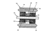
図1には、クローポール型ステッピングモータの一例が部分破断斜視図として示されている。図2a及び図2bは、ハイブリッド型ステッピングモータの一例を断面図及び部分破断斜視図としてそれぞれ模式的に示している。 FIG. 1 shows an example of a claw pole type stepping motor as a partially cutaway perspective view. 2a and 2b schematically show an example of a hybrid type stepping motor as a sectional view and a partially cutaway perspective view, respectively.
図1には、通常のクローポール型ステッピングモータが図示されている。このステッピングモータは、クローポール16、18を介して結合された第1のステータシステム10、第2のステータシステム12及び永久磁石ロータ14を含んでいる。
FIG. 1 shows a conventional claw-pole type stepping motor. The stepper motor includes a first stator system 10, a
図2a及び図2bに示すハイブリッド型ステッピングモータは、リラクタンスモータ(VRモータ)の要素と永久磁石モータ(PMモータ)の要素とを組み合わせたものである。図2a及び図2bに示すハイブリッド型モータは、ロータ22が装着された軸20を含んでいる。ロータ22は、S極環状歯車又は磁極ディスク24と、N極環状歯車又は磁極ディスク26とを含んでおり、これらの間に永久磁石28が配置されている。両方の磁極ディスク24、26と永久磁石28とは、保磁子30を介して軸20と結合されている。ロータ22は、ステータ32の内部で転がり軸受(図示せず)によって回転可能に軸支されている。ステータ32は、ステータ巻線38を支持するステータ磁極36と結合されたステータ保磁子34を含んでいる。
The hybrid stepping motor shown in FIGS. 2A and 2B is a combination of elements of a reluctance motor (VR motor) and elements of a permanent magnet motor (PM motor). 2a and 2b includes a
ハイブリッド型ステッピングモータは、通常のクローポール型ステッピングモータに比較して、減衰が優れており、自己保持モーメントを生成するという利点がある。始動周波数領域及び回転数に関する動作挙動は、クローポール型ステッピングモータの場合よりも優れており、容積及びサイズが同じならば、あるいは容積及びサイズが小さくても、出力はこちらのほうが高い。 The hybrid type stepping motor has an advantage that it has better damping and generates a self-holding moment as compared with a normal claw-pole type stepping motor. The operating behavior with respect to the starting frequency range and the rotational speed is better than that of the claw pole type stepping motor, and the output is higher when the volume and size are the same or even when the volume and size are small.
基本的に、ステッピングモータの信頼性を向上させるために、ステータを合成樹脂によりカプセル封止することが公知である。それによって、モータのロバスト性及び振動抵抗性が改善され、モータの熱的な絶縁が得られる。ステッピングモータのステータをカプセル封止するための最適な材料の一つは、例えばデュポン・ド・ネモン(Dupont de Nemon)社からRYNITE(登録商標)PETの商品名で提供されている。電気モータのステータをカプセル封止するための別の成形材料が欧州特許出願第EP0807644B1号明細書(特許文献1)に記載されている。同文献に記載されている成形材料は、モータのリサイクルが可能なように調合されている。注型又はカプセル封止されたステータを備えているその他の電気モータは、米国特許第6,020,661号明細書(特許文献2)やドイツ特許出願公開第DE−A−10133966号明細書(特許文献3)に記載されている。
本発明の課題は、材料及び製造について少ない経費及び費用により製造可能な、リニアドライブのための電気モータを提供することである。 It is an object of the present invention to provide an electric motor for a linear drive that can be manufactured with low costs and costs in terms of materials and manufacturing.
この課題は、請求項1乃至請求項6の構成要件を備えている電気モータによって解決される。 This object is achieved by an electric motor having the features of claim 1 to claim 6.
本発明は、ステータと、ロータと、ネジ付きシャフトとが内部に収容されたモータハウジングを備えている、リニアドライブのための電気モータに関するものである。ステータは、ステータ本体と、位相接続部に接続された位相巻線とを含んでいる。ロータは、ロータハブに装着されている。ロータハブは、転がり軸受を介してモータハウジングに軸支されるとともに、ロータの回転運動をネジ付きシャフトの並進運動に変換するために、ねじ山を介してネジ付きシャフトと連結されている。本発明の第1の観点においては、モータハウジングは、ステータがステータ本体及び位相巻線とともに内部に埋封された射出成形品を有しており、モータハウジングに、ネジ付きシャフトを収容、案内するための直線案内部が組み込まれている。本発明の第2の観点においては、ロータハブも、ロータが内部に固定された射出成形品によって形成されており、ロータハブは、ネジ付きシャフトの雄ネジと協働する雌ねじを有している。 The invention relates to an electric motor for a linear drive, comprising a motor housing in which a stator, a rotor and a threaded shaft are housed. The stator includes a stator body and a phase winding connected to the phase connection. The rotor is mounted on a rotor hub. The rotor hub is rotatably supported by the motor housing via rolling bearings and is connected to the threaded shaft via threads to convert the rotational movement of the rotor into the translation of the threaded shaft. In a first aspect of the present invention, a motor housing includes an injection molded product in which a stator is embedded together with a stator body and a phase winding, and accommodates and guides a threaded shaft in the motor housing. Linear guide for the vehicle is incorporated. In a second aspect of the invention, the rotor hub is also formed by an injection molded article having the rotor fixed therein, the rotor hub having a female thread cooperating with a male thread of a threaded shaft.
このように本発明においては、少なくともモータハウジング又はロータハブが、但し有利にはこの両者が、電気モータの主要な機能構成要素、即ち、ステータ及び/又はロータが内部に埋封された射出成形品として構成される。さらに、この射出成形品にリニアドライブの主要な機能部材が組み込まれ、即ち、ネジ付きシャフトのための直線案内部、及び/又は、ネジ付きシャフトの雄ネジと協働する雌ねじが組み込まれる。 Thus, in the present invention, at least the motor housing or the rotor hub, but preferably both, are the main functional components of the electric motor, i.e., the injection molded article in which the stator and / or the rotor are embedded. Be composed. In addition, the injection-molded part incorporates the main functional components of the linear drive, that is to say a linear guide for the threaded shaft and / or an internal thread cooperating with the external thread of the threaded shaft.
上述したような構造により、リニアドライブのための電気モータを、材料及び製造について最低限の経費及び費用により製造することが可能である。リニアドライブのための主要な機能部材、即ち、調節ロッド(ネジ付きシャフト)の直線案内部及びこれに付属するねじ山は、電気モータ自体の主要な機能部材、即ち、ステータ及びロータと同じく、前述した射出成形品に直接組み込まれる。これらの部材は、射出成形品によって正確に位置決めされて固定されるので、ステータ及びロータの組み付け、位置決め、保持のために追加の構成要素を必要としない。これに加えて、本発明の構造は、ステータ及びロータを互いに相対的に高い精度で位置決めし、これらの間に最低限の公差を有する正確な空隙を設定することを可能にする。本発明に係る電気モータのステータが完全にカプセル封止されることのさらに別の効果は、環境要因に対して、特に液体の浸入に対して、ステータが密閉、保護されることである。 With the structure as described above, an electric motor for a linear drive can be manufactured with a minimum of materials and manufacturing costs. The main functional components for the linear drive, namely the linear guides of the adjusting rod (threaded shaft) and the associated threads, are the same as the main functional components of the electric motor itself, namely the stator and rotor, as described above. Directly into injection molded products. These components are accurately positioned and secured by the injection molded article, so that no additional components are required for assembling, positioning, and holding the stator and rotor. In addition to this, the structure according to the invention makes it possible to position the stator and the rotor with a high precision relative to each other and to set up a precise gap between them with a minimum tolerance. A further advantage of the complete encapsulation of the stator of the electric motor according to the invention is that the stator is hermetically sealed and protected against environmental factors, in particular against ingress of liquid.
本発明の設計により、予想外に、前述した電気モータの精度、特に図2a及び図2bに示すようなハイブリッド型ステッピングモータの精度を、空隙に関して明らかに向上させることができ、それにより、偏心率を最低限に抑制することができる。モータの製造が簡素化されると同時に、明らかにコストが削減される。実験により判明したところでは、精度の向上により、従来式の設計を有するハイブリッド型ステッピングモータに比較しておよそ10%の性能改善を実現することができている。これに加えて、ねじ山が直接射出成形される本発明のロータハブの構成により、ロータとネジ付きシャフトとの間の壁厚を低減することができ、それによって逆に、モータ全体の設計サイズを増大させることなく、ロータの利用可能な磁石面を増加させることができ、それに伴って、ロータの体積に依存して決まる性能を向上させることができる。 With the design of the present invention, unexpectedly, the accuracy of the electric motor described above, especially of a hybrid stepping motor as shown in FIGS. 2a and 2b, can be significantly improved with respect to the air gap, whereby the eccentricity Can be minimized. The production of the motor is simplified, while the costs are obviously reduced. Experiments have shown that the improved accuracy has been able to achieve a performance improvement of approximately 10% compared to a hybrid type stepping motor having a conventional design. In addition, the configuration of the rotor hub of the present invention, in which the threads are directly injection molded, can reduce the wall thickness between the rotor and the threaded shaft, thereby conversely reducing the overall motor design size. Without increasing, the available magnet surface of the rotor can be increased, and consequently the performance dependent on the volume of the rotor can be improved.
本発明の有利な実施の形態においては、上記に加えて、モータハウジングの射出成形品に、直線案内部と協働してネジ付きシャフトの運動を制限する、ネジ付きシャフトを位置決めするためのストッパが組み込まれる。 In an advantageous embodiment of the invention, in addition to the above, a stopper for positioning the threaded shaft in the injection molded part of the motor housing, which cooperates with the linear guide to limit the movement of the threaded shaft. Is incorporated.
格別にコンパクトで好都合な設計形態は、ロータを軸支する転がり軸受のためのベアリングキャリヤもモータハウジングに組み込まれており、かつ、モータフランジがモータハウジングの射出成形品に直接一体成形されている場合に得られる。転がり軸受のための対応するベアリングキャリヤも、ロータハブに組み込まれているのが好ましい。 An exceptionally compact and convenient design is when the bearing carrier for the rolling bearing that supports the rotor is also integrated into the motor housing and the motor flange is directly integrated with the motor housing injection molding. Is obtained. A corresponding bearing carrier for the rolling bearing is also preferably integrated into the rotor hub.
本発明に係る電気モータは、ハイブリッド型ステッピングモータとして構成されるのが好ましく、この場合、ロータは、磁気ディスクによって分離された2個の磁極ディスクを有している。磁極ディスクと磁気ディスクとは、ロータハブにより保持、位置決めされるのが好ましい。 The electric motor according to the invention is preferably configured as a hybrid stepping motor, in which case the rotor has two pole disks separated by a magnetic disk. Preferably, the pole disk and the magnetic disk are held and positioned by a rotor hub.
次に、図面と関連する有利な実施の形態を参照しながら、本発明について詳細に説明する。 Next, the present invention will be described in detail with reference to advantageous embodiments related to the drawings.
図3は、本発明の有利な実施の形態に基づくリニアドライブのための電気モータを示している。図3に示す電気モータは、ハイブリッド型ステッピングモータである。本発明は、これ以外の電気モータにも適用可能であるが、このようなハイブリッド型ステッピングモータとの関連において採用するのが好ましい。 FIG. 3 shows an electric motor for a linear drive according to an advantageous embodiment of the invention. The electric motor shown in FIG. 3 is a hybrid stepping motor. The present invention is applicable to other electric motors, but is preferably employed in the context of such a hybrid stepping motor.
図3においては、電気モータ全体に符号40が付されている。この電気モータは、ロータ42とステータ44とを含んでいる。ロータ42は、永久磁石50によって分離された、第1の磁極ディスク46、例えばS極環状歯車と、第2の磁極ディスク48、例えばN極環状歯車とを有している。ロータ42は、ロータハブ52の上において位置決めされ、固定されている。
In FIG. 3,
ロータハブ52は、本発明によれば、ロータ42が内部に固定された射出成形品として構成されている。ロータ42は、ロータハブ52により部分的に押出被覆されていてよく、又は、ロータハブに挿入若しくは接着されていてよい。ロータ42とロータハブ52とのこれ以外の結合方法も考えられる。
According to the present invention, the rotor hub 52 is configured as an injection molded product in which the
ロータハブ52は貫通孔54を有しており、その中に雌ネジ(図3には図示せず)が形成されており、この雌ネジは、ロータハブ52の射出成形品とともに1回の製造工程により製作されるのが好ましい。
The rotor hub 52 has a through
貫通孔54にはネジ付きシャフト56が収容されており、このネジ付きシャフトはその長さの一部に雄ネジ58を備えており、この雄ネジがロータハブ52の雌ネジと協働して、ロータハブ52の回転運動をネジ付きシャフト56の並進運動に変換する。
The through-
さらに、ロータハブ52は、一体化されたベアリングキャリヤ60を有しており、このベアリングキャリヤは、ロータハブ52をステータ44に対して相対的に軸支するために、転がり軸受62、特に玉軸受を受容することができる。
Further, the rotor hub 52 has an
ステータ44は、例えば、積層された薄板スタックとして構成されるステータ本体64と、位相巻線66とを含んでいる。位相巻線66は、位相接続部68と接続されている。
The stator 44 includes, for example, a stator body 64 configured as a stacked thin plate stack and a phase winding 66. The phase winding 66 is connected to the
ステータ本体64と、位相巻線66と、位相接続部68とを備えているステータ44は、電気モータ40のモータハウジングを直接形成する射出成形品70に完全に埋封されている。これに代わる実施の形態においては、この射出成形品70が、特に金属からなる別個のモータ被覆によりさらに包囲されていてよい。便宜上、以下の説明では、射出成形品70のことをモータハウジングと称する。
The stator 44, comprising a stator body 64, a phase winding 66 and a
モータハウジング70は、ステータ44を完全に包囲しているので、ステータは、環境要因、特に液体の浸入に対して防護されている。モータハウジング70には、直線案内部72とストッパ73とがネジ付きシャフト56の位置決め及び案内のために組み込まれている。さらに、モータハウジング70は、転がり軸受62を受容するためのベアリングキャリヤ74を有している。モータフランジ76が、モータハウジング70の射出成形品に直接一体成形されており、また、位相接続部68を収容して電気モータを電力供給部及び/又は外部の制御部と接続するためのプラグ/ブッシュ部78も同様である。
Since the
転がり軸受62は、モータハウジング70の内部において波形ばね座金80又はこれに類似する部材を介して予圧がかけられている。
The rolling
図示した実施の形態においては、本発明に係る電気モータは、例えば、自動車の内燃機関の気化器のアイドリング制御弁を操作するためのバルブヘッド82に対するアクチュエータとしての役目を果たす。当業者であれば理解できるように、これは、本発明のリニアドライブの考えられる多数の用途のうちの一例に過ぎない。ネジ付きシャフト56は調節ロッドの機能を有しており、ロータハブ52が回転したときに回転方向に応じて、バルブヘッド82を図面で見て右方又は左方へと動かす。バルブヘッド82を案内、保持するために、取付部材84と、スリーブ88により包囲されたばね86が設けられている。これらの部材は、図示したバルブのリニアアクチュエータとして本発明に係る電気モータを利用するために固有のものであり、本発明に係るモータの別の用途では、適当な別の調節装置又は取付装置により置き換えることができる。
In the embodiment shown, the electric motor according to the invention serves, for example, as an actuator for a
以上の説明、特許請求の範囲及び図面に開示されている構成要件は、単独でも、それぞれ任意の組み合せとしても、様々な実施の形態において本発明を具体化するために有意義であり得る。 The components disclosed in the above description, the claims, and the drawings, alone or in any combination, may be significant for embodying the present invention in various embodiments.
10 第1のステータシステム
12 第2のステータシステム
14 ロータ
16 クローポール
18 クローポール
20 モータ軸
22 ロータ
24 S極環状歯車
26 N極環状歯車
28 永久磁石
30 保磁子
32 ステータ
34 ステータ保磁子
36 ステータ磁極
38 巻線
40 電気モータ
42 ロータ
44 ステータ
46 第1の磁極ディスク
48 第2の磁極ディスク
50 永久磁石
52 ロータハブ
54 貫通孔
56 ネジ付きシャフト
58 雄ネジ
60 ロータハブのベアリングキャリヤ
62 転がり軸受
64 ステータ本体
66 位相巻線
68 位相接続部
70 モータハウジング
72 直線案内部
73 ストッパ
74 モータハウジングのベアリングキャリヤ
76 モータフランジ
78 プラグ/ブッシュ部
80 波形ばね座金
82 バルブヘッド
84 取付部材
86 ばね
88 スリーブ
Reference Signs List 10
Claims (10)
前記ステータ(44)は、ステータ本体(64)と、位相接続部(68)に接続された位相巻線(66)とを有しており、
前記ロータ(42)は、ロータハブ(52)に装着されており、
前記ロータハブ(52)は、転がり軸受(62)を介して前記モータハウジング(70)に軸支されるとともに、前記ロータ(42)の回転運動を前記ネジ付きシャフト(56)の並進運動に変換するためにねじ山を介して前記ネジ付きシャフト(56)と連結されている形態の電気モータにおいて、
前記モータハウジング(70)は、前記ステータ(44)が前記ステータ本体(64)及び前記位相巻線(66)とともに内部に埋封された射出成形品を含んでおり、
前記モータハウジング(70)の射出成形品に、前記ネジ付きシャフト(56)を収容、案内するための直線案内部(72)が組み込まれていることを特徴とする電気モータ。 An electric motor for a linear drive, comprising a motor housing (70) in which a stator (44), a rotor (42), and a threaded shaft (56) are housed.
The stator (44) has a stator body (64) and a phase winding (66) connected to a phase connecting portion (68),
The rotor (42) is mounted on a rotor hub (52),
The rotor hub (52) is rotatably supported by the motor housing (70) via a rolling bearing (62) and converts the rotational motion of the rotor (42) into the translational motion of the threaded shaft (56). Motor connected to the threaded shaft (56) via threads for
The motor housing (70) includes an injection molded product in which the stator (44) is embedded together with the stator body (64) and the phase winding (66),
An electric motor characterized in that a linear guide (72) for accommodating and guiding the threaded shaft (56) is incorporated in an injection molded product of the motor housing (70).
前記ロータ(42)は、ロータハブ(52)に装着されており、
前記ロータハブ(52)は、転がり軸受(62)を介して前記モータハウジング(70)に軸支されるとともに、前記ロータ(42)の回転運動を前記ネジ付きシャフト(56)の並進運動に変換するためにねじ山を介して前記ネジ付きシャフト(56)と連結されている形態の電気モータにおいて、
前記ロータハブ(52)は、前記ロータ(42)が内部に固定された射出成形品を含んでおり、前記ロータハブ(52)の射出成形品は、前記ネジ付きシャフト(56)の雄ネジ(58)と協働する雌ねじを有していることを特徴とする電気モータ。 An electric motor for a linear drive, comprising a motor housing (70) in which a stator (44), a rotor (42), and a threaded shaft (56) are housed.
The rotor (42) is mounted on a rotor hub (52),
The rotor hub (52) is rotatably supported by the motor housing (70) via a rolling bearing (62) and converts the rotational motion of the rotor (42) into the translational motion of the threaded shaft (56). Motor connected to the threaded shaft (56) via threads for
The rotor hub (52) includes an injection molded article having the rotor (42) fixed therein, and the injection molded article of the rotor hub (52) includes an external thread (58) of the threaded shaft (56). An electric motor having an internal thread cooperating with the electric motor.
Applications Claiming Priority (1)
| Application Number | Priority Date | Filing Date | Title |
|---|---|---|---|
| DE10321966A DE10321966A1 (en) | 2003-05-15 | 2003-05-15 | Electric motor with linear drive |
Publications (1)
| Publication Number | Publication Date |
|---|---|
| JP2004343992A true JP2004343992A (en) | 2004-12-02 |
Family
ID=33394636
Family Applications (1)
| Application Number | Title | Priority Date | Filing Date |
|---|---|---|---|
| JP2004124982A Withdrawn JP2004343992A (en) | 2003-05-15 | 2004-04-21 | Electric motor for linear drive |
Country Status (3)
| Country | Link |
|---|---|
| US (1) | US20040227413A1 (en) |
| JP (1) | JP2004343992A (en) |
| DE (1) | DE10321966A1 (en) |
Cited By (1)
| Publication number | Priority date | Publication date | Assignee | Title |
|---|---|---|---|---|
| JP2008187830A (en) * | 2007-01-30 | 2008-08-14 | Nissan Motor Co Ltd | Reluctance motor rotor and reluctance motor including the same |
Families Citing this family (7)
| Publication number | Priority date | Publication date | Assignee | Title |
|---|---|---|---|---|
| DE102006023652B4 (en) * | 2006-05-18 | 2008-10-30 | Esa Patentverwertungsagentur Sachsen-Anhalt Gmbh | Electromotive device for actuating gas exchange valves |
| JP5534636B2 (en) * | 2007-10-26 | 2014-07-02 | キヤノン株式会社 | Motor and drive device |
| DK2447145T3 (en) * | 2010-10-29 | 2014-04-07 | Guenther Hirn | Electric drive system for a bicycle |
| DE102012007186A1 (en) * | 2012-04-12 | 2013-10-17 | Hanning Elektro-Werke Gmbh & Co. Kg | Electric motor and method for producing a stator for the electric motor |
| US20130334447A1 (en) * | 2012-06-13 | 2013-12-19 | Trane International Inc. | Electric Expansion Valve |
| DE102013000063A1 (en) | 2013-01-02 | 2014-07-03 | Bernd Burchard | Brushless electric-motor for linear drive for robot toy, has permanent magnet housed in rotor having translational degree of freedom for linear movement, and stator comprising multiple coils that generate rotating magnetic field |
| DE102014218212A1 (en) * | 2014-09-11 | 2016-03-17 | Continental Teves Ag & Co. Ohg | electric motor |
Family Cites Families (13)
| Publication number | Priority date | Publication date | Assignee | Title |
|---|---|---|---|---|
| US3621312A (en) * | 1970-09-22 | 1971-11-16 | Superior Electric Co | Simulated twelve-pole stepping motor having eight actual poles |
| US4672247A (en) * | 1984-12-27 | 1987-06-09 | North American Philips Corporation | Synchronous or stepping motor with equal-torque stepping |
| IT1182511B (en) * | 1985-07-12 | 1987-10-05 | Marelli Autronica | CONSTANT CURRENT CONTROL CIRCUIT FOR A SINGLE POLE STEP MOTOR, PARTICULARLY FOR USE ON BOARD MOTOR VEHICLES |
| JPS62136680U (en) * | 1986-02-21 | 1987-08-28 | ||
| US5254892A (en) * | 1991-12-30 | 1993-10-19 | North American Philips Corporation | Stepper motor with integrated assembly |
| US5806169A (en) * | 1995-04-03 | 1998-09-15 | Trago; Bradley A. | Method of fabricating an injected molded motor assembly |
| US5969009A (en) * | 1995-11-30 | 1999-10-19 | Matsushita Electric Industrial Co, Ltd. | Molding material and molded motor |
| JPH09247919A (en) * | 1996-03-08 | 1997-09-19 | Minebea Co Ltd | Structure of motor |
| DE19710470A1 (en) * | 1996-03-13 | 1997-09-18 | Unisia Jecs Corp | Drive worm unit and electric motor using the unit |
| JP3442643B2 (en) * | 1998-02-27 | 2003-09-02 | 三菱電機株式会社 | Step motor |
| US6492751B1 (en) * | 1999-01-29 | 2002-12-10 | Siemens Vdo Automotive Corporation | Magnetic device with spaced apart pole plates, flux return strip and electrical connector having integral mounting |
| JP2000228856A (en) * | 1999-02-05 | 2000-08-15 | Mitsubishi Electric Corp | Stepping motor |
| US6603229B1 (en) * | 2000-11-15 | 2003-08-05 | Tri-Tech, Inc. | Linear actuator with threaded captivation sleeve, captive lead screw, and spring pre-load adjustment |
-
2003
- 2003-05-15 DE DE10321966A patent/DE10321966A1/en not_active Ceased
-
2004
- 2004-03-31 US US10/813,172 patent/US20040227413A1/en not_active Abandoned
- 2004-04-21 JP JP2004124982A patent/JP2004343992A/en not_active Withdrawn
Cited By (1)
| Publication number | Priority date | Publication date | Assignee | Title |
|---|---|---|---|---|
| JP2008187830A (en) * | 2007-01-30 | 2008-08-14 | Nissan Motor Co Ltd | Reluctance motor rotor and reluctance motor including the same |
Also Published As
| Publication number | Publication date |
|---|---|
| DE10321966A1 (en) | 2004-12-16 |
| US20040227413A1 (en) | 2004-11-18 |
Similar Documents
| Publication | Publication Date | Title |
|---|---|---|
| KR890004253B1 (en) | Flow rate control valve system | |
| CN103930638B (en) | drive unit | |
| US8618700B2 (en) | Linear actuator | |
| US6946765B2 (en) | Rotor unit for an electromotor and an internal rotor electromotor | |
| JP2004236390A (en) | Small-sized brushless motor | |
| JP2002122203A (en) | Linear actuator | |
| CN100594653C (en) | motor | |
| CN103545973B (en) | Electric rotating machine | |
| CN100407559C (en) | Stepping motor | |
| JP2003348785A (en) | Motor | |
| KR20130071256A (en) | Motor of electrical parking brake | |
| US8022580B2 (en) | Plastics injection-molding machine with integrated, linear-rotary direct drive | |
| JP4259315B2 (en) | Electronically controlled throttle control device | |
| JP2004343992A (en) | Electric motor for linear drive | |
| KR20040033246A (en) | Actuator for operating a transmission control vlave of an automatic transmission apparatus | |
| US20160301291A1 (en) | Coreless motor for throttle controlling device, method for manufacturing coreless motor for throttle controlling device, and throttle controlling device | |
| JPH10274060A (en) | Throttle control device | |
| US20090115276A1 (en) | Outer rotor motor | |
| CN205779274U (en) | Ironless motor-driven throttle device | |
| JP2005168211A (en) | Stepping motor | |
| JP6529673B2 (en) | Automotive actuator | |
| JPH10142472A (en) | Lens drive mechanism | |
| JP6097513B2 (en) | Linear stepping motor | |
| JP2004124718A (en) | Electronic control throttle device | |
| JP2021093824A (en) | Motor and electric pump |
Legal Events
| Date | Code | Title | Description |
|---|---|---|---|
| A621 | Written request for application examination |
Free format text: JAPANESE INTERMEDIATE CODE: A621 Effective date: 20050125 |
|
| A761 | Written withdrawal of application |
Free format text: JAPANESE INTERMEDIATE CODE: A761 Effective date: 20070619 |
|
| A521 | Written amendment |
Free format text: JAPANESE INTERMEDIATE CODE: A821 Effective date: 20070619 |