JP2004347162A - Condenser - Google Patents
Condenser Download PDFInfo
- Publication number
- JP2004347162A JP2004347162A JP2003141848A JP2003141848A JP2004347162A JP 2004347162 A JP2004347162 A JP 2004347162A JP 2003141848 A JP2003141848 A JP 2003141848A JP 2003141848 A JP2003141848 A JP 2003141848A JP 2004347162 A JP2004347162 A JP 2004347162A
- Authority
- JP
- Japan
- Prior art keywords
- condenser
- heat exchange
- header pipe
- lubricating oil
- exchange medium
- Prior art date
- Legal status (The legal status is an assumption and is not a legal conclusion. Google has not performed a legal analysis and makes no representation as to the accuracy of the status listed.)
- Pending
Links
- 238000005192 partition Methods 0.000 claims abstract description 29
- 239000003990 capacitor Substances 0.000 claims description 11
- 239000010687 lubricating oil Substances 0.000 abstract description 27
- 230000005494 condensation Effects 0.000 abstract description 2
- 238000009833 condensation Methods 0.000 abstract description 2
- 239000007788 liquid Substances 0.000 description 6
- 239000003921 oil Substances 0.000 description 4
- 238000001816 cooling Methods 0.000 description 3
- 238000005461 lubrication Methods 0.000 description 3
- 238000005219 brazing Methods 0.000 description 2
- 238000010586 diagram Methods 0.000 description 2
- 230000000694 effects Effects 0.000 description 2
- 238000000926 separation method Methods 0.000 description 2
- 238000004378 air conditioning Methods 0.000 description 1
- 230000005540 biological transmission Effects 0.000 description 1
- 239000010725 compressor oil Substances 0.000 description 1
- 239000000446 fuel Substances 0.000 description 1
- 230000001050 lubricating effect Effects 0.000 description 1
- 239000010705 motor oil Substances 0.000 description 1
- 230000000704 physical effect Effects 0.000 description 1
- 230000005855 radiation Effects 0.000 description 1
- 230000000717 retained effect Effects 0.000 description 1
- 238000011144 upstream manufacturing Methods 0.000 description 1
Images


Landscapes
- Air-Conditioning For Vehicles (AREA)
Abstract
Description
【0001】
【発明の属する技術分野】
本発明は、熱交換媒体が上下方向に流れる、いわゆる縦流れコンデンサに関する。
【0002】
【従来の技術】
通常、自動車には、エンジン冷却用のラジエータや空調用のコンデンサ、オートマチック車用トランスミッションオイル冷却用のオイルクーラ(ATFクーラ)やエンジンオイル冷却用のオイルクーラ等、数々の熱交換器が配設されている。前記コンデンサとして、熱交換媒体が上下方向(縦方向)に流れる縦流れコンデンサが採用されている。この縦流れコンデンサは、コンプレッサとエバポレータとの間に直列に組み込まれており、コンプレッサで熱交換媒体を圧縮し、縦流れコンデンサで放熱して凝縮させたのち、リキッドタンクを介してエバポレータに送り出している。
【0003】
ここで、コンプレッサを潤滑するために熱交換媒体中には潤滑油を混入させており、コンデンサの上部ヘッダーパイプ内における熱交換媒体中の潤滑油の残留を防止すべく、上部ヘッダーパイプ内に挿入した熱交換用チューブの上端部に切欠きを形成している(例えば、特許文献1参照)。
【0004】
【特許文献1】
特開平10−185361号公報
【0005】
【発明が解決しようとする課題】
しかしながら、前記従来のコンデンサにあっては、上部ヘッダーパイプに滞留する潤滑油を下部ヘッダーパイプに流すように構成しているため、潤滑油は下部ヘッダーパイプに滞留したままで、潤滑を必要とするコンプレッサに潤滑油が十分に供給されず、コンプレッサの駆動トルクが上昇して燃費が低下するおそれがあった。
【0006】
そこで、本発明は、潤滑油成分を滞留させずに、コンプレッサに効率的に潤滑油を供給することができるコンデンサを提供することを目的とする。
【0007】
【課題を解決するための手段】
前記請求項1に記載されたコンデンサは、上下方向に間隔を隔てて上部ヘッダーパイプと下部ヘッダーパイプを配置し、これらのヘッダーパイプ同士を複数の熱交換用チューブによって連結する一方、前記熱交換用チューブの内部を長軸方向に画成する仕切壁を設け、この仕切壁に対応して、前記ヘッダーパイプと熱交換用チューブとを複数の凝縮部に画成したコンデンサであって、前記下部ヘッダーパイプに設けた仕切壁に連通孔を形成したことを特徴とする。
【0008】
前記請求項2に記載されたコンデンサは、請求項1に記載のコンデンサであって、前記連通孔を仕切壁の下端部に配置したことを特徴とする。
【0009】
【発明の効果】
前記請求項1に記載されたコンデンサによれば、下部ヘッダーパイプに設けた仕切壁に連通孔を形成しているため、熱交換媒体中から分離した潤滑油成分が連通孔を介して隣の凝縮部の下部ヘッダーパイプに送られたのち、熱交換媒体と共にコンデンサの外部に排出される。従って、コンデンサを含む熱交換システム内における潤滑油の循環量を十分に確保することができる。
【0010】
前記請求項2に記載されたコンデンサによれば、前記連通孔を仕切壁の下端部に配置しているため、請求項1による効果を更に高めることができる。コンデンサのヘッダーパイプ内に入った熱交換媒体中には潤滑油が含まれており、この潤滑油は分離している場合、潤滑油の方が密度が高いため下側に溜まる。従って、仕切壁の下端部に連通孔を設けることによって、連通孔を介して潤滑油を隣の凝縮部に更に効率的に移動させることができる。
【0011】
【発明の実施の形態】
以下、本発明の実施形態を図面に基づいて説明する。
【0012】
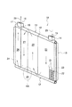
図1は、本発明の実施形態によるコンデンサ10を示す斜視図である。この図1に示すように、コンデンサ10は、上方に配設された円筒状の上部ヘッダーパイプ11と、下方に配設された円筒状の下部ヘッダーパイプ12と、これらの上部ヘッダーパイプ11及び下部ヘッダーパイプ12を上下に連結するコア部13とを備えている。
【0013】
上部ヘッダーパイプ11の入口側(図1の右側)には、入口ブロック14がろう付けによって取り付けられており、前記入口ブロック14には入口ポート15が貫通して設けられている。この入口ポート15は上部ヘッダーパイプ11の内部に連通して設けられている。また、上部ヘッダーパイプ11の出口側(図1の左側)には、出口ポート16が貫通して設けられた出口ブロック17がろう付けによって取り付けられている。また、上部ヘッダーパイプ11内には長手方向に間隔を隔てて2枚の仕切壁18,19が配設されており、これらの仕切壁18,19によって、上部ヘッダーパイプ11は長手方向に3室に画成されている。
【0014】
さらに、前記下部ヘッダーパイプ12は、上部ヘッダーパイプ11と一対になって配置されており、上部ヘッダーパイプ11における2枚の仕切壁18,19の中間部に対応する位置に1枚の仕切壁20が配設されている。この仕切壁20によって、下部ヘッダーパイプ12は長手方向に2室に画成されている。
【0015】
そして、前記コア部13は、上下方向に沿って延びる複数の熱交換用チューブ21と、これらの熱交換用チューブ21の間に配置されて左右に延びるフィン22とからなり、コア部13の左右両端には、サイドプレート23,24が取り付けられている。また、コア部13は、前記仕切壁18,19,20によって、入口ブロック14側から出口ブロック17側にかけてヘッダーパイプ11,12の長手方向に沿って、第1〜第4凝縮部25,26,27,28に画成されている。なお、コア部13の構成を明瞭にするため、図1では個々の熱交換用チューブ21とフィン22を一部のみ描いている。
【0016】
前記コンデンサ10においては、後述するように、図示しないコンプレッサから送られた熱交換媒体29は、入口ブロック14の入口ポート15から上部ヘッダーパイプ11に入り、コア部13の第1凝縮部25を介して下部ヘッダーパイプ12に流れ、この下部ヘッダーパイプ12内でUターン(第1ターン)して第2凝縮部26内を上昇する。次いで、上部ヘッダーパイプ11に流入し、この上部ヘッダーパイプ11内で再度Uターン(第2ターン)し、第3凝縮部27内を下方に流れ、下部ヘッダーパイプ12内でUターン(第3ターン)したのち、第4凝縮部28を上昇し、出口ブロック17から図示しないリキッドタンクに流れる。
【0017】
ここで、図1のA部を拡大した図2に示すように、下部ヘッダーパイプ12の仕切壁20近傍においては、熱交換媒体29から分離した潤滑油30が仕切壁20の流れ方向上流側に滞留しやすくなっている。以下、簡単に説明する。
【0018】
熱交換媒体29と潤滑油30とは、それらの物性値の相違から熱交換媒体29の温度によって熱交換媒体29に潤滑油30が溶解しない二層分離温度がある。例えば、熱交換媒体29としてHFC134aを、潤滑油30としてロータリコンプレッサ用オイルを用いた場合、二層分離温度は約60℃である。これは、通常の外気温度でエアーコンデショナーを作動させたときでも十分に二層分離してしまう温度である。コンデンサ10に入った直後の熱交換媒体29は気体の状態であるため、潤滑油30の密度の方が高く、二層に分離したときは密度の高い潤滑油30は、熱交換媒体29よりも下側に滞留する。また、図2に示すように、仕切壁20近傍は熱交換媒体29が上方に流れを変更する部位であるため、本来的に滞留が生じやすくなっている。
【0019】
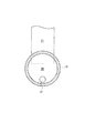
本実施形態においては、図2,3に示すように、仕切壁20に真円状の連通孔31が穿設されている。この連通孔31は、仕切壁20の板厚方向に貫通して設けられており、仕切壁20の高さ方向の下端部に配置されている。本実施形態では、連通孔31を1つにしたが、これに限定されずに2つ以上でも良く、形状も真円に限らずに楕円等でも良い。
【0020】
次いで、本実施形態による熱交換媒体29の流れを図4を用いて説明する。
【0021】
図4は、本実施形態によるコンデンサ10を含む熱交換器システム内における熱交換媒体29の流れを示す概略図である。
【0022】
まず、熱交換媒体29にはコンプレッサ32を潤滑するための潤滑油30が含まれており、この熱交換媒体29をコンプレッサ32で圧縮したのち、コンデンサ10に送る。コンデンサ10においては、図2で説明したように、仕切壁20の下端部に形成した連通孔31を介して分離した潤滑油30が隣の第3凝縮部27側に流動する。第3凝縮部27の熱交換媒体29はコンデンサ10の放熱によって冷却されて熱交換媒体29に潤滑油30が十分に溶解する温度となっている。よって、この流動した潤滑油30は熱交換媒体29中に溶解してそのまま熱交換媒体29と一緒に、出口ポート16からリキッドタンク33に流れる。さらに、熱交換媒体29は膨張弁34とエバポレータ35を介してコンプレッサ32に流れ、前述した流れを繰り返す。
【0023】
このように、本実施形態によれば、コンプレッサ用の潤滑油30が熱交換媒体29中に混入した場合でも、コンデンサ10の下部ヘッダーパイプ12に滞留することなく流れるようになる。従って、潤滑を必要とするコンプレッサ32に潤滑油が十分に供給されれてコンプレッサ32の駆動トルクの上昇を回避することができる。
【0024】
本発明に係るコンデンサは、前述した実施形態に限定されることなく、種々の変更及び変形が可能である。
【0025】
例えば、前記実施形態ではリキッドタンク33が別体のコンデンサについて説明したが、本発明は縦流れ形式のコンデンサであれば、リキッドタンク一体型やサブクール付きコンデンサ等、種々のコンデンサに適用することができる。
【図面の簡単な説明】
【図1】本発明の実施形態によるコンデンサを示す斜視図である。
【図2】図1のA部を拡大した断面図である。
【図3】図2のB−B線による断面図である。
【図4】本発明の実施形態による熱交換器システム内の熱交換媒体の流れを示す概略図である。
【符号の説明】
11…上部ヘッダーパイプ
12…下部ヘッダーパイプ
18,19,20…仕切壁
21…熱交換用チューブ
25…第1凝縮部
26…第2凝縮部
27…第3凝縮部
28…第4凝縮部
31…連通孔[0001]
TECHNICAL FIELD OF THE INVENTION
The present invention relates to a so-called longitudinal flow condenser in which a heat exchange medium flows in a vertical direction.
[0002]
[Prior art]
Normally, automobiles are provided with a number of heat exchangers such as a radiator for cooling an engine, a condenser for air conditioning, an oil cooler for cooling transmission oil for automatic vehicles (ATF cooler) and an oil cooler for cooling engine oil. ing. As the condenser, a vertical flow condenser in which a heat exchange medium flows in a vertical direction (longitudinal direction) is employed. This vertical flow condenser is built in series between the compressor and the evaporator, compresses the heat exchange medium with the compressor, radiates and condenses it with the vertical flow condenser, and sends it out to the evaporator via the liquid tank. I have.
[0003]
Here, lubricating oil is mixed in the heat exchange medium to lubricate the compressor, and inserted into the upper header pipe to prevent the lubrication oil from remaining in the heat exchange medium in the upper header pipe of the condenser. A notch is formed at the upper end of the heat exchange tube (for example, see Patent Document 1).
[0004]
[Patent Document 1]
JP-A-10-185361
[Problems to be solved by the invention]
However, in the conventional condenser, since the lubricating oil retained in the upper header pipe is configured to flow to the lower header pipe, the lubricating oil remains in the lower header pipe and requires lubrication. Lubricating oil may not be sufficiently supplied to the compressor, and the driving torque of the compressor may increase to lower the fuel efficiency.
[0006]
Therefore, an object of the present invention is to provide a condenser that can efficiently supply lubricating oil to a compressor without retaining lubricating oil components.
[0007]
[Means for Solving the Problems]
The condenser according to claim 1, wherein an upper header pipe and a lower header pipe are arranged at intervals in a vertical direction, and these header pipes are connected to each other by a plurality of heat exchange tubes, while the heat exchange pipes are connected to each other. A condenser in which a partition wall that defines the inside of the tube in the longitudinal direction is provided, and the header pipe and the heat exchange tube are defined in a plurality of condensing sections corresponding to the partition wall, wherein the lower header is provided. A communication hole is formed in a partition wall provided in the pipe.
[0008]
The capacitor described in claim 2 is the capacitor according to claim 1, wherein the communication hole is arranged at a lower end portion of a partition wall.
[0009]
【The invention's effect】
According to the condenser described in the first aspect, since the communication hole is formed in the partition wall provided in the lower header pipe, the lubricating oil component separated from the heat exchange medium is condensed to the adjacent condensation via the communication hole. After being sent to the lower header pipe of the section, it is discharged outside the condenser together with the heat exchange medium. Therefore, the circulation amount of the lubricating oil in the heat exchange system including the condenser can be sufficiently ensured.
[0010]
According to the capacitor described in the second aspect, since the communication hole is disposed at the lower end of the partition wall, the effect according to the first aspect can be further enhanced. The heat exchange medium contained in the header pipe of the condenser contains lubricating oil. When the lubricating oil is separated, the lubricating oil has a higher density and accumulates on the lower side. Therefore, by providing the communication hole at the lower end of the partition wall, the lubricating oil can be more efficiently moved to the adjacent condensing section via the communication hole.
[0011]
BEST MODE FOR CARRYING OUT THE INVENTION
Hereinafter, embodiments of the present invention will be described with reference to the drawings.
[0012]
FIG. 1 is a perspective view showing a
[0013]
An
[0014]
Further, the
[0015]
The
[0016]
In the
[0017]
Here, as shown in FIG. 2 which is an enlarged view of the portion A in FIG. 1, in the vicinity of the
[0018]
The
[0019]
In the present embodiment, as shown in FIGS. 2 and 3, a
[0020]
Next, the flow of the
[0021]
FIG. 4 is a schematic diagram illustrating a flow of the
[0022]
First, the
[0023]
As described above, according to the present embodiment, even when the lubricating
[0024]
The capacitor according to the present invention can be variously modified and modified without being limited to the embodiments described above.
[0025]
For example, in the above embodiment, the
[Brief description of the drawings]
FIG. 1 is a perspective view showing a capacitor according to an embodiment of the present invention.
FIG. 2 is an enlarged sectional view of a portion A in FIG.
FIG. 3 is a sectional view taken along line BB of FIG. 2;
FIG. 4 is a schematic diagram showing a flow of a heat exchange medium in a heat exchanger system according to an embodiment of the present invention.
[Explanation of symbols]
11
Claims (2)
前記下部ヘッダーパイプ(12)に設けた仕切壁(20)に連通孔(31)を形成したことを特徴とするコンデンサ。An upper header pipe (11) and a lower header pipe (12) are arranged at intervals in the vertical direction, and these header pipes (11, 12) are connected to each other by a plurality of heat exchange tubes (21). Partition walls (18 to 20) which define the inside of the header pipes (11, 12) in the longitudinal direction are provided, and the header pipes (11, 12) and the heat pipes (11, 12) correspond to the partition walls (18 to 20). A condenser in which a replacement tube (21) is defined in a plurality of condensing sections (25 to 28),
A communication hole (31) is formed in a partition wall (20) provided in said lower header pipe (12).
Priority Applications (1)
| Application Number | Priority Date | Filing Date | Title |
|---|---|---|---|
| JP2003141848A JP2004347162A (en) | 2003-05-20 | 2003-05-20 | Condenser |
Applications Claiming Priority (1)
| Application Number | Priority Date | Filing Date | Title |
|---|---|---|---|
| JP2003141848A JP2004347162A (en) | 2003-05-20 | 2003-05-20 | Condenser |
Publications (1)
| Publication Number | Publication Date |
|---|---|
| JP2004347162A true JP2004347162A (en) | 2004-12-09 |
Family
ID=33530099
Family Applications (1)
| Application Number | Title | Priority Date | Filing Date |
|---|---|---|---|
| JP2003141848A Pending JP2004347162A (en) | 2003-05-20 | 2003-05-20 | Condenser |
Country Status (1)
| Country | Link |
|---|---|
| JP (1) | JP2004347162A (en) |
Cited By (5)
| Publication number | Priority date | Publication date | Assignee | Title |
|---|---|---|---|---|
| KR100600148B1 (en) | 2004-12-20 | 2006-07-13 | 현대자동차주식회사 | Receiver drier of car air conditioner |
| JP2006226563A (en) * | 2005-02-15 | 2006-08-31 | Calsonic Kansei Corp | Evaporator for carbon dioxide air conditioner |
| WO2014181546A1 (en) * | 2013-05-10 | 2014-11-13 | 株式会社デンソー | Refrigerant evaporator |
| KR20190138576A (en) * | 2018-06-05 | 2019-12-13 | 한온시스템 주식회사 | Device for transferring heat in a refrigerant circulation |
| WO2024261909A1 (en) * | 2023-06-21 | 2024-12-26 | 三菱電機株式会社 | Heat exchanger and air conditioner |
-
2003
- 2003-05-20 JP JP2003141848A patent/JP2004347162A/en active Pending
Cited By (10)
| Publication number | Priority date | Publication date | Assignee | Title |
|---|---|---|---|---|
| KR100600148B1 (en) | 2004-12-20 | 2006-07-13 | 현대자동차주식회사 | Receiver drier of car air conditioner |
| JP2006226563A (en) * | 2005-02-15 | 2006-08-31 | Calsonic Kansei Corp | Evaporator for carbon dioxide air conditioner |
| WO2014181546A1 (en) * | 2013-05-10 | 2014-11-13 | 株式会社デンソー | Refrigerant evaporator |
| JP2014219174A (en) * | 2013-05-10 | 2014-11-20 | 株式会社デンソー | Refrigerant evaporator |
| CN105378422A (en) * | 2013-05-10 | 2016-03-02 | 株式会社电装 | Refrigerant evaporator |
| US9951996B2 (en) | 2013-05-10 | 2018-04-24 | Denso Corporation | Refrigerant evaporator |
| CN105378422B (en) * | 2013-05-10 | 2018-11-13 | 株式会社电装 | refrigerant evaporator |
| KR20190138576A (en) * | 2018-06-05 | 2019-12-13 | 한온시스템 주식회사 | Device for transferring heat in a refrigerant circulation |
| KR102199408B1 (en) * | 2018-06-05 | 2021-01-06 | 한온시스템 주식회사 | Device for transferring heat in a refrigerant circulation |
| WO2024261909A1 (en) * | 2023-06-21 | 2024-12-26 | 三菱電機株式会社 | Heat exchanger and air conditioner |
Similar Documents
| Publication | Publication Date | Title |
|---|---|---|
| CN100565069C (en) | Refrigerating module | |
| US5592830A (en) | Refrigerant condenser with integral receiver | |
| RU2227883C2 (en) | Two-phase heat-exchanger with liquid cooling (variants) | |
| JP2010175241A (en) | Heat exchanger for two fluids, in particular, storage evaporator for air conditioning device | |
| JP2008180486A (en) | Heat exchanger | |
| JP2000346568A (en) | Heat exchanger | |
| JPH10206074A (en) | Integral type heat-exchanger | |
| JPH11105538A (en) | Heat exchange equipment for vehicles | |
| JP2013170732A (en) | Heat exchanger | |
| JPH10325645A (en) | Refrigerant evaporator | |
| JP2001147095A (en) | Heat exchanger | |
| JP4248931B2 (en) | Heat exchanger | |
| CN1470841A (en) | laminated heat exchanger | |
| JP2006329511A (en) | Heat exchanger | |
| JP2004340442A (en) | Complex heat exchanger | |
| JP2004347162A (en) | Condenser | |
| JP2008267730A (en) | Double heat exchanger | |
| JP2008175508A (en) | Combined heat exchanger | |
| US20070056718A1 (en) | Heat exchanger and duplex type heat exchanger | |
| CN105737453A (en) | Cooling device and application method thereof | |
| JP4743203B2 (en) | Heat transfer body for automobile | |
| JP2008267753A (en) | Heat exchanger | |
| JP2002350002A (en) | Condenser | |
| JP2004347158A (en) | Condenser | |
| KR100790382B1 (en) | Manufacturing method of tube for heat exchanger |
Legal Events
| Date | Code | Title | Description |
|---|---|---|---|
| A621 | Written request for application examination |
Effective date: 20060324 Free format text: JAPANESE INTERMEDIATE CODE: A621 |
|
| A977 | Report on retrieval |
Effective date: 20081224 Free format text: JAPANESE INTERMEDIATE CODE: A971007 |
|
| A131 | Notification of reasons for refusal |
Free format text: JAPANESE INTERMEDIATE CODE: A131 Effective date: 20090106 |
|
| A02 | Decision of refusal |
Effective date: 20090929 Free format text: JAPANESE INTERMEDIATE CODE: A02 |