JP2004347310A - Ice making equipment, freezer refrigerator, ice making method - Google Patents
Ice making equipment, freezer refrigerator, ice making method Download PDFInfo
- Publication number
- JP2004347310A JP2004347310A JP2003197940A JP2003197940A JP2004347310A JP 2004347310 A JP2004347310 A JP 2004347310A JP 2003197940 A JP2003197940 A JP 2003197940A JP 2003197940 A JP2003197940 A JP 2003197940A JP 2004347310 A JP2004347310 A JP 2004347310A
- Authority
- JP
- Japan
- Prior art keywords
- ice
- making
- generating unit
- tray
- ice making
- Prior art date
- Legal status (The legal status is an assumption and is not a legal conclusion. Google has not performed a legal analysis and makes no representation as to the accuracy of the status listed.)
- Granted
Links
Images






Classifications
-
- F—MECHANICAL ENGINEERING; LIGHTING; HEATING; WEAPONS; BLASTING
- F25—REFRIGERATION OR COOLING; COMBINED HEATING AND REFRIGERATION SYSTEMS; HEAT PUMP SYSTEMS; MANUFACTURE OR STORAGE OF ICE; LIQUEFACTION SOLIDIFICATION OF GASES
- F25C—PRODUCING, WORKING OR HANDLING ICE
- F25C1/00—Producing ice
- F25C1/18—Producing ice of a particular transparency or translucency, e.g. by injecting air
-
- F—MECHANICAL ENGINEERING; LIGHTING; HEATING; WEAPONS; BLASTING
- F25—REFRIGERATION OR COOLING; COMBINED HEATING AND REFRIGERATION SYSTEMS; HEAT PUMP SYSTEMS; MANUFACTURE OR STORAGE OF ICE; LIQUEFACTION SOLIDIFICATION OF GASES
- F25D—REFRIGERATORS; COLD ROOMS; ICE-BOXES; COOLING OR FREEZING APPARATUS NOT OTHERWISE PROVIDED FOR
- F25D2400/00—General features of, or devices for refrigerators, cold rooms, ice-boxes, or for cooling or freezing apparatus not covered by any other subclass
- F25D2400/02—Refrigerators including a heater
Landscapes
- Engineering & Computer Science (AREA)
- Physics & Mathematics (AREA)
- Mechanical Engineering (AREA)
- Thermal Sciences (AREA)
- General Engineering & Computer Science (AREA)
- Production, Working, Storing, Or Distribution Of Ice (AREA)
- Devices That Are Associated With Refrigeration Equipment (AREA)
Abstract
Description
【0001】
【発明の属する分野】
この発明は、製氷装置において氷を生成する際に、製氷皿に供給された水の中に溶存する気体成分やイオン成分などを分離し、透明度の高い氷を得る製氷を行う技術に関するものである。
【0002】
【従来の技術】
従来、家庭用の冷凍冷蔵庫などにおいては、給水装置から供給された水を製氷皿に貯留して製氷し、製氷後に駆動装置で製氷皿を反転して離氷させ、この氷をためておく自動製氷装置が普及している。しかし、一般的には白濁した氷が形成される。
【0003】
一般的に物質が結晶を形成する場合、単一の成分で結晶が形成される。水が凍結して氷になる場合も同様であるため、水中に溶解している不純物は凍結過程で氷―水界面に排出され、氷―水界面では不純物が過飽和状態になっている。そして、過飽和水層の不純物が水中に拡散する速度よりも氷の成長する速度が大きい場合、氷は不純物を取り込みながら成長し氷はこの取り込んだものにより白濁する。
【0004】
氷が白濁して見えるのは、氷に光を反射して白く見える部分が形成されるためであるが、これは水中に溶解した物質、特に氷中に溶存しているガス成分(CO2、O2など)が微小な気泡として氷に閉じ込められているためである。氷の中に入った光は、気泡表面で屈折したり反射したりする。気体成分の体積としては同一であっても、より細かい気泡が沢山形成されているほうがそれだけ光の経路が変えられる確率は高くなる、すなわち光が散乱反射しやすくなるため、白っぽく見えるようになる。
【0005】
ただし、一般的に目にする氷は、透明度によらず、多くの単結晶氷が固まってできる多結晶氷であり、結晶間に供給水中に溶解していた物質が残っている場合が多い。従って、透明な氷を作る目的は、氷の実際の味向上よりはむしろ見た目のおいしさ感や美しさを追及することにあり、食品に関係する冷蔵庫では大きな問題になり多くの公知技術が知られている。
【0006】
例えば製氷皿を多数のコアなで連結された2重構造としたもの(特許文献1参照)、この製氷皿をヒーターを設けた断熱槽の開放面に取り付けた自動製氷装置が提案されている(特許文献2参照)。また不純物の入っている水を貯水したり水切り排水し、一部を揚水する技術がある(特許文献3参照)。
【0007】
【特許文献1】
特許2524811号公報(第6図、第10図など)
【特許文献2】
実開平6−4561号公報(図1など)
【特許文献3】
特許登録第2781429号(請求項1など)
【0008】
【発明が解決しようとする課題】
従来の製氷装置では、透明氷を得る部分と白濁水を集める部分の間を連通する孔が小さいと、水の表面張力により下皿に水が入っていかず、上皿に白濁氷ができる可能性があったり、氷の体積膨張による圧力で、製氷皿が破損する危険性があるという問題があった。更に給水時セパレータ下部に気泡が溜まることがある。この気泡が、上皿氷表面が凍結し、脱気面がなくなってから浮き上がってくることで、異形の氷が形成される。また離氷時、皿底面全体にわたり固体層の厚みが大きくなることにより、離氷時のひねりトルクが大きくなりモーター寸法のみならず余分なエネルギーが必要になるという問題があった。更に離氷後、下皿氷を溶かすために、10W程度の高入力で30〜60分連続通電を必要とし、製氷皿下に設けられた貯氷箱内の氷や他室への影響、消費電力が悪化するなど実用にならないという問題があった。更に、氷融解後の水を給水タンクに戻す機構や氷を水から引上げ、乾燥させるための水切り篭などが必要というごとく構造が複雑になり、寸法が大きく、且つ、製造費用もかかるという問題があった。
【0009】
本発明は、以上のような問題点を解決するためになされたもので、氷の不出来を解消でき、また、白濁氷融解水を処理する機構が不要であり、安価な構成部材で透明度の高い氷を精製できる製氷装置および製氷方法を提供することを目的とする。更に本発明は透明氷を簡単に製造できるエネルギーの少ない装置、方法を得ることが目的である。更に本発明はおいしそうな透明氷を食品収納部分のスペースを減らさずに得られる実用的な冷蔵庫を提供することを目的としている。
【0010】
【課題を解決するための手段】
本発明の製氷装置は、区画された複数の製氷ブロックに給水をそれぞれ貯留し冷気を受けて製氷を行うとともに機械力を加えられて生成された氷が離氷可能な製氷皿と、製氷皿に区画された製氷ブロックに設けられ冷気を受けて製氷が促進される第1の氷生成部と、第1の氷生成部といったいに設けられ設けられ第1の氷生成部と開口部にて給水が連通し第1の氷生成部より冷気を受ける影響を少なくして製氷を遅らせる第2の氷生成部と、第1の氷生成部で生成された氷に開口部を通じて連続して製氷される第2の氷生成部で生成された氷と、を備え、開口部は開口部近傍の氷が機械力を受けて切断可能な寸法および形状とするものである。
【0011】
本発明の製氷装置は、区画された複数の製氷ブロックに給水をそれぞれ貯留し冷気を受けて製氷を行うとともにひねりを与えられ生成された氷が離氷する製氷皿と、製氷皿に区画された製氷ブロックに設けられ冷気を受けて製氷が促進される第1の氷生成部と、製氷ブロックに設けられ第1の氷生成部と開口部にて給水が連通し第1の氷生成部より冷気を受ける影響を少なくして製氷を遅らせられる第2の氷生成部であって、第1の氷生成部よりも生成された氷が製氷皿から分離しにくい寸法および形状とする第2の氷生成部と、を備え、製氷皿がひねりを受けて開口部近傍で切断された第1の氷生成部で生成された氷が離氷するものである。
【0012】
本発明の製氷装置は、区画された複数の製氷ブロックに給水をそれぞれ貯留し冷気を受けて製氷を行うとともに生成された氷が離氷可能な製氷皿と、製氷皿に区画された製氷ブロックに設けられ冷気を受けて製氷が促進される第1の氷生成部と、製氷ブロックの下方に設けられ第1の氷生成部と開口部にて給水が連通し第1の氷生成部より冷気を受ける影響を少なくして製氷を遅らせる第2の氷生成部と、第1の氷生成部で生成された氷に開口部通じて接続される第2の氷生成部で生成された氷と、を備え、第1の氷生成部は製氷皿の開放面に開放され、第2の氷生成部は第1の氷生成部と連通する開口部へ膨張可能に開放されているものである。
【0013】
本発明の製氷方法は、製氷室に配置され製氷皿の上方より冷気を吹き付けて、製氷皿上面を開放して設けた第1の氷生成部の製氷を促進するステップと、第1の氷生成部の下方に設けられ第1の氷生成部と連通する第2の氷生成部を加熱して第1の氷生成部よりも製氷を遅らせるステップと、第1の氷生成部での氷の生成状態により加熱を停止させ製氷させるステップと、製氷皿にひねりを加え第2の氷生成部の氷と第1の氷生成部で生成された氷とを切断させるステップと、を備えたものである。
【0014】
【発明の実施の形態】
実施の形態1.
以下、本発明の実施の形態1について、図1から図5に従い説明する。
【0015】
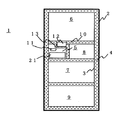
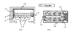
図1は本発明にかかる製氷装置が適用された家庭用冷凍冷蔵庫の正面断面図で、正面の扉を除いた場合の状態を説明している。図2(a)は本発明にかかる製氷皿の側断面図で(b)は製氷装置の上面図、図3は製氷装置の上面図、図4、5は本発明にかかる製氷皿の横断面図である。
【0016】
冷凍冷蔵庫本体1は、外箱2、内箱3、および外箱2と内箱3の間に充填された断熱材4により構成され、食品を収納する複数の区画が設けられ、製氷室5の上部に設置された冷蔵室6、製氷室5の下部に設置された野菜室7、冷凍冷蔵庫1の扉に設けられた図示されていない操作パネルによりエンドユーザが任意に温度を設定できる切替室8、冷凍室9などがあり、各室を区画形成する断熱材4を充填した区画壁10で分けられている。なお図1では貯氷箱21と製氷皿11を同じ製氷室5の中に収納する例を説明しているがこれらを別の室に設けてもかまわない。また、前出の図示しない操作パネルは、冷蔵庫の各部屋の温度調節や運転モードをエンドユーザが選択したり、現状の各部屋の温度や運転モードなどを表示しエンドユーザに伝えることができる。
【0017】
図2、図3などに記載されている製氷皿11は製氷室5内に設置され、ポリプロピレンなどの樹脂材質からなる成型品であり、上面は開口し、その内側が凹状に形成された複数の製氷ブロックに区画され、図2(a)(b)の空気の流れが示すように製氷皿11の上面である開放面に冷蔵庫壁面から送風機により吹き出される冷気を受けて上部から氷が生成され、上面を冷却した冷気は下部に循環して再び冷蔵庫壁面に吸い込まれている。図3のように隣接する製氷ブロック間の壁面には、皿の内側寄りに設けられた各ブロックに給水を流し込みやすくする切り欠き溝で結ばれているものもある。また図1のようにこの製氷皿11に給水する水を貯留する給水タンク12から製氷皿11に水を流す給水配管13が設けられており、図示されていないが、この給水配管13の出口には凍結防止のためのヒータが設けられ、制御装置からの指示に基づき給水配管の電磁弁を開閉し製氷皿11へ一定量の給水が行われる。図2の製氷皿11の支持軸14を回転駆動するモータおよび減速ギアなどを内蔵した駆動装置15がフレーム16に設置されている。支持軸14の一端は製氷皿11を支持するフレーム16に連通し、他端を前記駆動装置15に接続し、離氷時に、この駆動が行われ製氷皿11が反転したときに、製氷皿11の反転を制限しひねりを加え脱氷を促進するストッパー17もフレーム16に設けられている。製氷皿に加えられるひねりは駆動装置が支持軸を回転させて製氷皿がストッパー17にて停止しても、更に支持軸を例えば45゜廻すことにより製氷皿にひねりが加えられストッパー側と駆動装置側で製氷皿が変形することになる。
【0018】
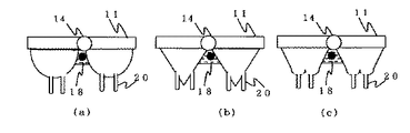
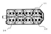
製氷皿11の水がほぼ凍結したことを認識できるような位置、例えば製氷皿11下部には、図4で示すサーミスタおよび直接サーミスタに冷気があたらないようサーミスタ下部に設けた断熱材からなる温度センサ18が取り付けられている。製氷皿11底面に設けられた開口部19と一体に成型され、製氷皿11と開口部19で連通し、給水した水が貯められる溝状の突起部20が下方に突出して設けられている。この突起部20は、区画された上部の複数の製氷ブロックごとに設けられている。更に製氷装置の下方には、製氷皿11から反転して離氷した氷を受け止め貯氷する貯氷箱21がある。このように製氷皿が製氷する区画は上部の複数の製氷ブロック部である第1の氷生成部とこれより大幅に少ない内容積である溝状の突起部20である第2の氷生成部からなっている。
【0019】
なお、図示されていないが、冷凍冷蔵庫本体1には冷媒を圧縮する圧縮機、冷媒を絞るキャピラリーチューブ、ガス状態の冷媒の熱を庫外に放熱して凝縮させる凝縮器、液状態の冷媒を気化させ得られる冷熱で庫内空気を冷却する冷却器、冷却器等の冷凍サイクルと、この冷却機を通過し各室へ冷気を運ぶ通気ダクトと送風機、および各室への冷気供給量を調節するダンパ等の冷気循環装置と、冷蔵庫の各機器動作を制御する制御基板等の制御装置がある。これらの装置により冷気を供給して冷蔵庫内各個室の温度を変化させたり所定の温度に保ったり、霜取りや製氷、照明などの制御を行っている。
【0020】
次に、図2から図5に基づいて本実施例にかかわる製氷動作の工程の一例を述べる。まず、給水タンク12から給水配管13を通って製氷皿11の一部に水が供給され切り欠き溝を通り各製氷ブロックへ水が供給される。さらにこのとき、開口部19を通り突起部20にも水が供給される。なお、切り欠き溝は、突起部20に水が流れ込みやすいように、開口部19と直列の位置に設けられていてもよい。また、開口部19が複数ある場合には、それぞれの開口部19と直列になるように、一つの製氷ブロック間壁面に複数の切り欠き溝があってもよい。
【0021】
なお本発明の図面や説明では、突起部20を各ブロックごとに下方に複数軸方向に長い溝形状で設けている例で説明しているが、これは製氷皿を離氷時に捻りやすくしてモーターのトルクを従来と大差ないものとすることや、製氷皿反転時にこの回転半径内に突起部20を収めるようにして製氷装置全体の寸法を増加させないためであり、この突起部の位置や寸法、形状、方向等が製氷皿をねじりやすい位置、寸法、形状、方向等で回転半径内に収まったりこの回転半径を大きく超えるものでなければ、例えば円が連続している溝のようなものや、各ブロック毎でなく複数のブロックにつながっていたり、製氷皿の内側側面に開口部を設けるなどの、構造でもよいことは当然である。またこの第2の氷生成部の内容積を大きくしすぎると透明氷の生成により時間がかかり、また使用するエネルギーが大きくなる。一方あまり小さすぎると透明度が低下する氷しか得られない。実用的な時間、例えば3.5時間以内にエネルギーをあまり増やさずに透明氷を生成しようとすると突起部内容積は製氷皿の離氷する内容積の10−20パーセントぐらいが望ましい。
【0022】
開口部19は、水が流れる少なくとも一方向に延びた形状をしている。最大長さは製氷皿11の氷一粒づつ形成される製氷ブロック長さである。これによって、水の表面張力に負けずに突起部20に水を流し込むことができる。さらに他の一方向は、これよりも短い形状である必要がある。例えば5mm以下、最適であるのは2〜3mm幅である。これによって、製氷完了後、駆動装置15およびストッパー17により製氷皿11に加えられる離氷のためのひねりにより氷が開口部19近傍で破断することができる。すなわち突起部20はその入り口である開口部19が最も面積を大きくするが細長くすることによりスムースな給水や離氷時の切断に都合が良い。このような開口部形状として想定される最も簡易な形状は、例えば長方形や楕円形などであるが、突起部19に給水時に確実に水が入り、かつ離氷時に開口部19近傍で氷が破断できるのであれば、他のいかなる形状であっても構わない。
【0023】
また、突起部20は、極端に細い部分がない形状としたり水のたまる位置に蓋をかぶせたりするような形状を避けるなど、水が流入したときに気泡が溜まりにくいと想定される方向、位置、形状から選択されれ場よく、その場合は横向きなどでもよく他に制限される要素はない。また、その深さも同様に気泡が溜まりにくい高さである。その条件内であれば、突起部20は、開口部19の形状・大きさを開口部19垂直方向へ押し出した形状でなく、開口部19から離れるにつれ縮小または拡大した形状であってもよい。また、突起部底面は必ずしも平面である必要はなく、水流が滑らかに突起部20に入るように円弧状または傾斜がついた、例えば逆三角形のような形状であってもよい。また、突起部20は、製造上の容易さからそれぞれ独立した形状として記載したが、より水流が流れやすい形状として、任意の個数が連結した形を取ってもよい。開口部近傍で切断しやすい開口の形状は支持軸が軸の両端でねじられる形となるため、軸に沿って平行な細長い開口が氷の破談のためには余り力が必要とせず望ましい。但し開口の形状は図に示すストレートな長方形以外でも、波状やくの字状でも細長く軸に沿って設けられておれば良く、更に円がつながって細長い形状などどのようなものでも力が大きくならなければ駆動装置への影響は小さい。
【0024】
なお、製氷皿底面についても平面として記載したが、これに限定されるものではなく、図5に示すように、皿底面が湾曲していたり、V字型であったり、突起部周囲のみが落ち込んだ形で湾曲していたりと、任意の形状であって構わない。このような形状をとることで、氷の厚みが増して見えるので、同一体積の氷でも大きな氷に見える効果が得られる。
【0025】
次に、供給された水は製氷室5で凍結される。一般的に、低温部に晒されている面から凍結が始まる。その際、氷は水分子でのみ結晶を形成し、水に溶解していた物質(Caなどのミネラル成分やO2、CO2などの気体成分)は全て結晶の外の未凍結部に放出される。このとき、5mm/時間程度以下という凍結速度は十分遅いため、始めのうちは溶解した物質が、凍結速度よりも速く未凍結部に拡散し、透明な氷が生成され、その後、過飽和に達した気体成分が大きく集積し、光の散乱反射をある程度抑止した大気泡が1つまたは複数形成され、気泡入りグラスのような、透明度には影響しない氷のアクセントを得た意匠的に優れた氷を生成することができる。製氷皿のブロックごとにこのような過程で透明な氷が生成されていく。
【0026】
この凍結時に、凍結速度が拡散速度を下回るように製氷皿11上面から冷気を供給し、製氷皿11の側面とフレーム16の隙間を通り貯氷箱21と製氷皿11下面の間の空間を通って流れていく。このとき、製氷皿11の上面は下面よりも低温かつ高風速の空気に接しているため、凍結は主に製氷皿11の上面から下面に向かって進行し、水に溶解していた物質のほとんどは未凍結部、すなわち製氷皿11下部へ向かって拡散していく。さらに凍結が進むと、突起部20のみ未凍結部となり製氷皿11には透明な氷が形成され、最後に突起部20が水に溶解していた物質のほとんどを含む形で白濁凍結して製氷が完了する。
【0027】
この過程で、氷の体積は約10%増加する。従って、増加した体積分氷が伸張できる開放空間がないと、体積膨張の圧力により製氷皿が破損する可能性がある。従来例にある製氷皿のように、製氷皿内に仕切りを設けた構造では、仕切に圧力がかかり、そこから製氷皿が破損する。本発明では、製氷皿11においても突起部20内においても、体積膨張した分、氷は製氷皿11上方の開放空間に向かって伸張していくため、製氷皿11および突起部20には、通常の製氷皿と同程度の力しかかからず、破損の危険性もない。すなわち開口部19の開口と突起部の内容積の関係は氷の膨張に対しこれを制限する蓋が無く開かれており、面積や方向も氷の上の開放空間への伸びを制限するもので無いので信頼性の高い装置ができる。
【0028】
このような動作を効果的に行うためには、突起部20を最も凍結の遅い部位に設置する必要がある。例えば、製氷速度が氷水平面どの位置でも常に同等であれば、突起部は底面の任意の位置に設置してもよいが、例えば製氷皿側面で、製氷皿外側のほうがより冷気が回り、冷却が早く進むのであれば、製氷皿11底面の内側に少なくとも一つは突起部20を設ける必要がある。なお、突起部20の個数や配置は特に限定しない。また、ここでは開口部19および突起部20を製氷皿11底面に設置するように記載したが、製氷皿11側面に設置されていても構わない。
【0029】
突起部20は、製氷皿11に形成される氷の透明度に影響のない程度にまで、溶解していた物質を集積するために必要な容積を持つ。製氷速度によってその体積は異なるが、製氷時間約1時間であれば体積の約60%、製氷時間約3時間で約10%、製氷時間3.5時間で約5%である。おおよそ1時間から3時間ぐらいで製氷させると家庭用冷蔵庫の食品としての透明氷生成には実用的である。すなわち短い時間で生成させると透明度が中途半端になるし、あまり長い時間かけると、すなわち氷の生成速度を2mm/時間というような長い時間かけると、より透明な氷が得られるが、冷蔵庫に必要な生成する透明氷の量が不足する。ただしこれは製氷する水の量にもよるので、少なくとも3.5時間以内を製氷サイクルとして透明氷を生成することが望ましい。
【0030】
製氷が終わると、離氷を行う。離氷のタイミングは、製氷皿11から離氷した氷が完全に凍結し、貯氷箱21に落下する際に製氷皿11からも突起部20からも水が落下してこない状態である。この状態が可能であれば、製氷皿11または突起部20に未凍結部が残っていても構わない。
【0031】
離氷動作に移るタイミングは、温度センサ18があらかじめ製氷完了と確認できるある温度になったときである。ただし、このタイミングは給水開始や給水後温度センサ18があらかじめ設定した温度検出時など、冷蔵庫内の任意の動作を基点に算出された所定時間経過後としてもよく、さらに、温度と時間双方を併用した動作によってもよい。このタイミング検知により、先に述べたように、駆動装置15およびストッパー17により製氷皿11に加えられる離氷のためのひねりにより氷が開口部19近傍で破断する。
【0032】
このとき、突起部20周囲は所定の温度以下になっていなくてはならない。所定の温度とは、突起部20の氷の周辺部が融解し、製氷皿11の氷に突起部20の氷が連結した状態で離氷する可能性を回避できる温度帯の上限値が望ましいがこれより低い温度であればよい。
【0033】
また、製氷皿11の氷は開口部19近傍以外で破断することなく、且つ開口部19近傍で破断した後、速やかに落下する仕様をとる必要がある。まず、製氷皿11の側面が底面から上方に向けて外側に向けて十分な傾斜角度をとることである。具体的には側面の少なくとも一面、例えば製氷皿11を駆動装置15およびストッパー17による離氷動作後に最も残氷性の高い個所近傍の面、の傾斜角度は鉛直方向に対し少なくとも10゜以上の傾斜角度を取ることが望ましい。また製氷皿から離氷される氷をスムースに落下させるため製氷皿側面の傾斜角度を大きくするだけでなく、皿側面内部の氷と製氷皿の摩擦を最小限にすべく型磨きを十分にした金型にて成型することが望ましい。具体的には型磨きレベルを透明プラスチック製品レベル(#2000)まで加工してあると離氷に有利である。なお、本製氷皿のような構造を取る場合、離氷トルクは現在一般的に自動製氷に用いられている製氷皿から氷を離氷する際のトルクと殆ど変わらないので、従来例で示した製氷皿のように高トルク化が必要な場合の新規部品追加などが不要で、寸法が変わること無く、且つ製造費用が上がらない。
【0034】
また、上述のように製氷皿11の上方がより広い面積を取れることで、製氷皿下方よりも冷却速度を早くする効果が促進される。
【0035】
さらにこのような製氷皿を反転させて捻り離氷させるとき、突起部20の内面側にて生成された氷は落下しない仕様をとる必要がある。まず、突起部20の側面が底面から上方に向けて外側に向けて必要最低限の傾斜角度(例えば10°以下の角度)をとるものとする。必要最低限の傾斜角度とは、離氷動作で氷は取れないが、製氷皿11および開口部19および突起部20からなる部材を成型する際に、型からは確実に抜ける、という角度の範囲内にあることを示す。これにより製氷皿内側表面である側面の角度は突起部内側の側面の角度より大きい、言い換えると突起部側の側面角度を製氷皿側の側面角度より小さくすることになる。この角度の違いは金型の角度を変えてもよいし、金型の側面に相当する部分の磨き方を変えても良い。
【0036】
さらに、突起部20内部が磨かれていないことである。前述のように、供給水が突起部20により流れ込みやすくするために側面に傾斜を大きくつけたい場合には、さらに表面を粗くすることにより、さらに突起部20内に氷を留めておくことがより確実となる。
【0037】
さらに、突起部20の高さは、離氷時に氷が抜けない任意の高さで、部材の肉厚込みで製氷皿11横幅最大部と支持軸14の位置で規定される回転軌跡の半径範囲内に収まる高さである必要がある。突起部20の高さを製氷皿11横幅最大部よりも長く取り、回転軌跡の半径を突起部20の高さで設定しても構わないが、その場合、フレーム16の幅変更など、製氷室5内の製氷皿11および開口部19および突起部20以外の構成部品の構造まで変更しなくてはならなくなるため、より安価な製造方法とることができるものとしては、突起部19の高さを、上述のように製氷皿11横幅最大部で規定される回転軌跡の半径範囲内に収まる高さに収めることが望ましい。
【0038】
また、前述のように、突起部20の個数は限定していない。このため、支持軸14に近い位置と遠い位置に設置することも可能であるが、このとき、当然のことながら支持軸14に近い方が製氷皿11の底面から回転軌跡までの距離は長い。従って、支持軸14に近い位置の突起部20は、支持軸14に遠い位置の突起部20よりも長くしてあってもよい。これによって、製氷が製氷皿11の上面のみでなく側面からも徐々に製氷されていく場合に、より溶解した物質を多量に含み白濁部を形成しやすい水を突起部20に閉じ込め凍結させることができる。
【0039】
この離氷動作の後、給水し、次のサイクルの製氷工程に入るが、このとき、給水された水により突起部20内に残る氷は徐々に融解する。融解は、突起部20に残る氷上面のみでなく、側面からも水が徐々に回り込み、融解していくので、突起部底まで十分に水が回り込むと、突起部20に残っていた氷は浮き上がり、製氷皿11に貯留されている水によって融解されながら混合していく。なお、このとき製氷皿11に貯留された水の表面が完全に凍結していなければ、気体成分は水面から放出されるため、次の製氷工程で白濁成分が大幅に増加することがない。
【0040】
なお、貯氷箱21に蓄えられる氷の透明感を明確にするために、製氷箱21内部を氷の透明度明瞭にする配色にしたり、青色LEDを照射するなど、透明度を効果的に演出できる配色や明るさなどの環境を整えていてもよい。
【0041】
さらに、冷蔵庫運転開始時や製氷皿清掃後の1回目の製氷時、すなわち突起部20に水又は氷が存在しない場合とそれ以外の場合で、常に同一の大きさの氷を供給するために、後者で供給水量を突起部20の体積分減らしてもよい。
【0042】
上記説明では、製氷皿11上方から冷却する方法について述べたが、次に突起部近傍にヒータなどの加熱手段を備える構成を次に説明する。これにより、白濁部を形成する物質を確実に突起部に追い込み、製氷皿に透明氷を生成することができ、離氷後の給水時に突起部20の氷が製氷皿11の貯留水中に浮上するまでの時間を短縮できる。以下、図6〜図13に従い説明する。なお、以下の説明で、先の説明と等しいものに関しては説明を省略する。
【0043】
図6は本発明にかかる製氷装置の説明図で(a)は側断面図、(b)は上面図、図7、8は本発明にかかる製氷皿の横断面図、図9は本発明にかかる製氷皿を上面から見て製氷皿下に設置したヒーターを投資した図、図10は本発明にかかる製氷工程のフローチャート、図11は本発明にかかる製氷工程のタイムチャート、図12、13は本発明にかかる製氷実験結果の一例である。
【0044】
ニクロム線などの発熱体を、シリコンゴムなどで被覆したコードヒータ22を製氷皿11の下側に設け、図9に示すように、製氷皿11の各製氷ブロック毎に設けられた突起部20の間に密着するように設置している。ヒータ22は、低温でもひび割れたりしない耐寒性のある部材でかつ離氷時の製氷皿ひねりに追随できる柔軟性を持つ部材、例えばシリコン材等で形成されている必要がある。また、ヒータをなるべくコンパクトに設置するために、図9に示すように最大でも製氷皿11の側面外周程度と非常に短い長さにしており、発熱密度が高くても変質しない部材であることも必要である。ただし、このヒータは、製氷室5が十分に冷却されておらず、かつ給水もない空焼き状態でも製氷皿11を含む冷蔵庫本体1のあらゆる部材を変形・故障させないものであり、二重絶縁されているなど、安全面でも十分な信頼性を持つ。製氷皿に取り付けられるヒーターの発熱本体はこの製氷皿を人が触ったり水にぬれることがあるため金属面等発熱部が剥き出しにされることがなく、しかも2重絶縁にするため安全なものになる。
【0045】
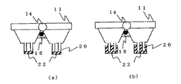
このヒータ22を製氷皿11の底面に密着させると、その部分も凍結速度が突起部20同様に遅くなり白濁部が形成されてしまう可能性がある。ただし、不必要に離しすぎると製氷皿11の底面からも凍結が進み、開口部19が閉塞され、製氷皿11には白濁部の多い氷が形成される可能性がある。これらを回避するために、製氷皿11の底面には突起部20に供給されるよりは少ない熱が供給されるようなヒータ設置構造を取る必要がある。これは、例えば、図7、8に示されるように、ヒータ22を突起部20の側面に密着させ第1の氷生成部分である製氷皿11底面からはやや離した(例えば2〜5mm程度離した)構造を取るとよい。
【0046】
また、加熱手段であるヒータ22の設置位置をより容易に確実にするために、ヒータ22を製氷皿11底面に接するように設置したい場合には、ヒータ22の被覆内部の発熱体をわざと製氷皿11の底面と反対側に偏らせて成形したものを用いてもよい。また、製氷皿11の底面のヒータ22に接する部位で、皿厚みを増してもよく、製氷皿11とヒータ22間に断熱材を設置してもよい。
【0047】
上述のように、突起部20が2つある場合はその間に挟みこむようにして設置したが、製氷皿11底面との距離を明確に保つために突起部20底面に設置してもよい(図8(a))。また、ヒータ22の設置が容易なように、突起部20全体を覆うように設置してもよい(図8(b))。いずれにしても、凍結を最も遅らせたい位置に効率的に熱を供給できるように設置してあれば、いかなる設置位置であっても構わない。
【0048】
なお、このヒータ22も離氷時の回転軌跡内に設置させる必要があることは、自明である。ヒータ22の設置方法としては、複数の突起部20に挟みこむようにして設置する方法だけでなく、突起部20が一つしかない場合には、突起部20と並行に設けた止め板を設け、その間に挟みこんでもよい。また、突起部20とヒータ22をアルミテープなど熱伝導性の高い部材で被覆し、突起部20全体に熱が効率的に伝わるように設置してもよい。また、ヒータ22の落下を防止できる爪止め構造を設けてもよい。また、この爪止め構造は、温度センサ18の設置カバーと一体成形されたものであってもよい。
【0049】
上述の説明ではヒータ22は1本であるものとして説明したが、製氷皿11の上面からの冷却量が製氷ブロック部位毎に大きく異なる、例えば冷風の当たり方に大きな差異がある、などの場合には、ヒータ22を複数本設置し、個別の入力を与えてもよい。また、ヒータ22は突起部20に密着するものとして記載したが、上述全てと同等の伝熱効果が得られるものであれば必ずしも突起部20に密着せず、離れた位置にあってもよい。またヒーターの周りを断熱材で覆いこの加熱手段が発生する熱の大半が突起部20である第2の氷生成部のみに伝わるようにすると効率的に加熱することができる。
【0050】
上述のように設置されたヒータ22は、連続通電でもよいが、図10、11に示すように給水後から、一定期間通電し、その後断電することで、使用するエネルギー量を低減し製氷速度を上げても透明度の高い氷を得ることができる。
【0051】
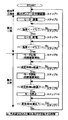
図10、11で示した制御方法に沿って、ヒータ22の制御動作を含む製氷動作について説明する。ステップ1にて図11のごとく給水用電磁弁を通電させて給水ポンプを一定時間動作させ定められた水量を製氷皿11に給水する。ステップ1で行われた給水完了直後にステップ2でヒータ22に通電が開始される。これにより、前回のサイクルで突起部に内蔵され残された氷は水の供給と加熱により解かされ、不純物などや貴方が製氷皿全体に広がり一部は開放面から放出される。ステップ3で、温度センサ18の出力が、実験などによって求められた製氷皿11内の水の凍結と相関のある値をもとに設定された所定の温度Ta、例えば−1度より低い温度に達するまで一定量の通電を行う。所定の温度Taに達したらステップ4でヒータを断電する。このとき、製氷皿11には透明氷が形成されているが、突起部20の水はまだ未凍結部が残っている状態である。ヒータ22が断電し加熱を停止することで突起部20の中の未凍結部は急速に凍結する。これは突起部20に熱供給が無くなり、冷蔵庫の製氷室5環境を形成する冷気にさらされるためである。
【0052】
ステップ5で、温度センサ18の出力が、実験などによって求められた突起部20内の水の凍結と相関のある値をもとに設定された所定の温度Tbに到達したと判断されると、ステップ6から始まる離氷工程に移る。ステップ6で離氷用駆動装置15が正転し、製氷皿11を反転させていき、ステップ7で時間tr経過するまで正転方向に動作し続ける。このとき、製氷皿11の一端がストッパ−17に押しつけられ皿がひねられ、捩れることによる開口部19にかかる応力で製氷皿11と突起部20の氷が分断し、製氷皿11の氷は貯氷箱21に落下する。ステップ8で駆動装置15が逆転し、製氷皿11を元の位置に向けて回転させ、ステップ9で時間tr経過するまで逆転方向に動作し続け、ステップ10で製氷皿11が元の位置に戻り、駆動装置15が停止する。この離氷時には突起部20の中の氷はそのまま残ることになる。ステップ11で、貯氷箱21が満氷であるかどうか検知し、この給水、製氷、離氷を行う工程が1サイクルの製氷工程であり、満氷になるまでステップ1に戻り製氷動作サイクルを繰り返す。
【0053】
上述の制御に基づいた実験結果一例を図12に示す。横軸は製氷時間、縦軸は氷の透明度である。例えば透明度95%以上のものを得たい場合、最適な製氷時間約2.5〜3.5時間程度である。この領域よりも製氷時間が早いものは、ヒータ22の通電量が小さい場合やヒータ22を断電するタイミングが早すぎた場合である。また、遅いものは、ヒータ22の通電量が大きい場合やヒータ22を断電するタイミングが遅すぎた場合である。さらに、供給水量を変えた場合は、より少ない水量では、一点鎖線で示すように同一の透明度を得る為の製氷時間が早くなり、より多い水量では、破線で示すように同一の透明度を得るための製氷時間が遅くなる。透明度を若干低くしても早く満氷にしたい場合は温度Taを高くしたり通電量を低く抑えると良い。透明氷を大量に必要としない場合は設定温度Taをより低くしたり通電量を大きくし、更に水量を増やすと良い。
【0054】
ヒータ22の能力は、冷却能力によって決まる。冷却能力が大きくなればヒータ22の能力も比例的に大きなものを選択する必要がある。ただし、このとき、製氷室5に貯氷箱21を設けている場合は、貯氷箱21内に貯められている氷がヒータ22からのふく射熱で融解したりすることがないようにする必要がある。図13は、貯氷箱内に、ある熱容量を持つ物質を置き、その中心の温度変化を見たものである。ヒータ22通電開始前後で、温度は大きな変化がなく、ヒータ22が通電している間中に大幅に昇温することもない。従って、通常の家庭用冷蔵庫の製氷室5構造で、貯氷箱21内の氷に熱的な影響をほとんど与えない構造を検討することが可能であることがわかる。
【0055】
なお、ヒータ22の通電タイミングを給水完了直後としたが、突起部20に流入した水が凍結し始めないうちに通電開始できるタイミングがあればいつでもよく、例えば、給水開始と同時に、または、温度センサ18で検出される温度が所定温度に到達したとき、または、これらのタイミングから所定の時間が経過したときなどであってもよい。
【0056】
突起部20への加熱を停止するヒータ22の断電タイミングに関しても同様で、温度センサ18で検出される温度が所定温度に到達したとき以外にも、製氷皿11に供給された水がほぼ凍結し、突起部20には未凍結部が多く残る状態で断電できるタイミングであればいつでもよく、例えば、上述のヒータ22の通電開始タイミングから所定時間経過後、または上述のヒータ22の通電開始タイミングから所定時間経過後に温度センサ18で検出される温度が所定温度に到達したときなどであってもよい。
【0057】
また、製氷中のヒータ22の通電量を一定としたが、これを任意に変化させてもよい。例えば、冷蔵庫の圧縮機オンオフなどによる、冷却量の増減に伴ってヒータ22の通電量を増減させることで、透明度に影響なく製氷スピードを早めつつ製氷時の消費電力量を低減できる。また、製氷皿への冷気吹き付けがなくなるデフロスト時に通電量を低減又は断電することでも、やはり透明度に影響なく製氷スピードを早めつつ製氷時の消費電力量を低減できる。
【0058】
次に、製氷皿の清掃方法について説明する。冷蔵庫に具備した図示しない制御基板は、製氷した回数を記憶する。そしてあらかじめ設定された所定の回数に達したときに、図示しない操作パネル上に、例えばLEDを点滅させるなどの方法で、エンドユーザに清掃を勧める。エンドユーザは、例えば、図示しない操作小パネル上に設置された清掃スイッチを押して清掃モードを動作させる。これによりヒータ22に通電を開始し、突起部20内の氷を融解し、その後製氷皿を反転して排水させることができる機構を設けておく。このことにより、突起部20に供給水中に含まれるミネラル成分が残存していたとしても除去できるため、いつまでも清潔に透明氷を得ることができる。なおこの排水機構は製氷皿を反転させる正転時に突起部20内から流れ出した排水を蓄えておけばよく簡単な機構で寸法を増加させるものとはならない。また融解を促進するために給水しても良い。更に、給水と排水の動作を複数回行い、より清掃効果があがるようにしても良い。
【0059】
また、別の清掃方法として、清掃モードを動作させると、製氷皿11に給水・製氷し、製氷完了後、ヒータ22に、突起部20の氷周囲のみを融解できる時間だけ通電し、その後製氷皿を反転して製氷皿11と突起部20に形成された氷がつながった状態で排出されることで、突起部20に残存するミネラル成分を除去してもよい。
【0060】
また、冷蔵庫本体1には、通常製氷と透明製氷を、エンドユーザが選択できるスイッチが設け、通常製氷を選択するときはヒータ22の動作を停止し、あらかじめ設定された時間で製氷を行う動作に切り替えができるので、エンドユーザの意思で消費電力量を節約することもできる。
【0061】
この発明にかかわる冷蔵庫は、複数の製氷ブロックに区画され水を貯留し製氷する一重構造の製氷皿において、前期製氷ブロック毎に氷生成部を複数設けた製氷皿を搭載し氷の透明部と白濁部を分離させてエンドユーザに透明な氷を提供することが可能な製氷装置である。これにより従来の冷蔵庫に設けられていた製氷装置と同程度の構造と寸法でエネルギーもほとんど増やさずに透明な氷を得ることができる。水を貯留し製氷する製氷皿の一部に穴を設けた第1の氷生成部と第1の氷生成部に設けた穴と同一形状の開口部を有する第2の氷生成部を一体で製造しており、このような一重構造の製氷皿の成型は、2つの金型間のキャビティに溶融させた樹脂を射出させて成型させることに製氷皿と突起部を一体にしたものを簡単な製造装置で短時間に製造できる。しかも製氷皿の第1の氷生成部の皿の内側表面が、前記第2の氷生成部の皿の内側表面よりも滑らかである様に、上の製氷皿に相当する金型の内側に相当する壁面の表面をつるつるにし、下の突起部の内側に相当する壁面を磨くことなくそのままとしておけばよい。
【0062】
本発明の製氷皿内側側面および突起部内側側面が、下面側から上面側に向かい外側に傾斜させ、更に製氷皿である第1の氷生成部の皿の側面の下面側から上面側に向かう傾斜角度が、突起部である第2の氷生成部の皿の側面の下面側から上面側に向かう傾斜角度よりも鉛直方向に対し大きな角度としておくことにより製氷皿からは離氷しやすく、突起部の氷は簡単に離氷しない。この場合、第1の氷生成部において、製氷皿側面が下面側から上面側に向かい外側に大きい角度で傾斜させ離氷させやすくしてもよいが、ねじりを与えるのでそのひねり角度によって決まるものでもあるので、上の製氷皿からは氷のブロックが抜けやすく、下の突起部からは抜けにくい角度であれば良い。
【0063】
本発明の突起部である第2の氷生成部に近接した加熱手段に対し、少なくとも冷却手段は加熱手段と対向する面を冷却することが望ましい。この加熱手段は、第1の氷生成部よりも離しておくことが望ましい。
【0064】
次に、ウイスキーをロックや水割りで飲む場合などに要求される見た目の良い(意匠性のよい)大きな透明氷(通常の製氷による通常の氷の大きさよりも大きな透明氷)の製造方法について説明する。本実施の形態では、製氷皿11への給水量を可変にしてユーザの満足する大きさの氷を得ることを目的としている。図14は、本発明の実施の形態1を表す冷蔵庫の製氷行程のフローを説明する図、図15は、給水量を可変させた場合の製氷行程のタイムチャートを説明する図である。
【0065】
図を用いて、ヒータ22および給水ポンプ23の制御動作を含む製氷動作について説明する。本実施の形態では、例えば図示しない冷蔵庫本体正面あるいは側面あるいは庫内壁などに設けられた操作パネルに透明氷を選択できる製氷モード切替ボタンを設けており、ユーザがこの製氷モード切替ボタンを透明氷に切替えるか、あるいは切替ボタンではなく透明氷選択ボタンが設けられたものにおいては、透明氷ボタンが押されたかなど、透明製氷モードが選択されているかどうかをステップ31にて判定して給水量の調節を行う。
【0066】
ステップ31にて透明氷製氷モードが選択されている場合には、ステップ32にて図示しない制御装置がステップ31にて透明氷製造指令を受け、この制御装置にあらかじめ設定された給水ポンプ駆動時間t1だけ給水ポンプ23を駆動し製氷皿11へ給水する。透明製氷モードが選択されていない場合にはステップ33であらかじめ図示しない制御装置に設定された給水ポンプ駆動時間t2だけ給水ポンプ23を駆動し製氷皿11へ給水する。このとき、ポンプの駆動時間t1は駆動時間t2より長い時間であり、例えばt1=10秒、t2=7秒などt1/t2=1.1〜3程度に設定すればよい。すなわち、ステップ31で製氷モードを判断して、ステップ32、ステップ33にて製氷皿11への給水量を変更して氷の大きさを変更している。
【0067】
ステップ33で製氷皿11への給水が行われたときは、そのままステップ37に進む。このとき、前回のサイクルで製氷皿11の突起部20に内蔵され残された氷は水の供給と加熱により解かされ、不純物などや気泡が製氷皿全体に広がり一部は開放面から放出される。ステップ32で駆動時間t1にて製氷皿11への給水が行われたときは、給水完了直後にステップ34でヒータ22に通電が開始される。このとき、前回のサイクルで製氷皿の突起部20に残された氷は今回の水の供給とヒータ22による加熱により解かされ、不純物などや気泡が製氷皿全体に広がり一部は製氷皿11の開放面から放出される。
【0068】
ステップ35で、温度センサ18の出力が、実験などによって求められた製氷皿11内の水の凍結と相関のある値をもとに設定された所定の温度Ta(例えば−1度より低い温度)に達するまで一定量の通電を行う。所定の温度Taに達したらステップ36にてヒータ22への通電を断電する。このとき、製氷皿11の中の第1の氷生成部には透明氷が形成されているが、突起部20の水はまだ未凍結部が残っている状態である。ヒータ22が断電し加熱を停止することで突起部20の中の第2の氷生成部内は急速に凍結する。これは冷蔵庫の冷凍室を形成する−18度の冷気が供給されているためである。
【0069】
ステップ37で、温度センサ18の出力が、実験などによって求められた突起部20内の水の凍結と相関のある値をもとに設定された所定の温度Tbに到達したと判断されると、ステップ38から始まる離氷工程に移る。なお、ここではステップ37の設定値Tbは、製氷モードによらず同一の値(例えば−6度)が、例えば透明製氷モード選択時は−10度、通常製氷モード選択時は−6度というように、製氷モードによって設定値Tbを変えてもよい。ステップ38で離氷用駆動装置15が正転し、製氷皿11を反転させていき、ステップ39で時間tr経過するまで正転方向に動作し続ける。
【0070】
このとき、製氷皿11の一端がストッパ−17に押しつけられ皿がひねられ、捩れることによる開口部19にかかる応力で製氷皿11と突起部20の氷が分断し、製氷皿11の氷は貯氷箱21に落下する。ステップ40で駆動装置15が逆転し、製氷皿11を元の位置に向けて回転させ、ステップ41で時間tr経過するまで逆転方向に動作し続け、ステップ42で製氷皿11が元の位置に戻り、駆動装置15が停止する。この離氷時には突起部20の中の氷はそのまま残ることになる。ステップ43で、貯氷箱21が満氷であるかどうか検知し、この給水、製氷、離氷を行う工程が1サイクルの製氷工程であり、満氷になるまでステップ31に戻り製氷動作サイクルを繰り返す。
【0071】
また、透明氷を生成する際において、このように給水量を増加させることは透明氷の生成手段において大きな氷を生成でき、氷の意匠性改善につながるので、本実施の形態で説明した第1の氷生成部、第2の氷生成部を設けた製氷皿による透明製氷方式以外においても有効である
【0072】
本発明は、以上説明したように、自動製氷装置が設置されている通常の冷蔵庫の製氷室構成部材に大幅な変更を加えることなく、異形な氷形成を回避でき、また、容易な製造方法で安価に製氷皿を製造でき、貯氷箱内の氷に悪影響を与えることなく、清掃性にも優れた製氷装置を提供できる。この結果実用的な冷蔵庫を得ることができる。また、製氷皿への給水時間(ポンプの駆動時間)を可変にする給水量可変手段を備えているので、給水時間を通常よりも長くして製氷皿への給水量を多くすることにより意匠性の優れた大きな透明氷を造ることができる。
【0073】
また、区画された複数の製氷ブロックに給水をそれぞれ貯留し冷気を受けて製氷を行うとともに機械力を加えられて生成された氷が離氷可能な製氷皿11と、前記製氷皿への給水量を可変する給水量調節手段である制御装置と、を備え、透明氷の製造指令を受けた場合に製氷皿11への給水量を多くするようにしたので、通常の製氷時に比べて製氷皿11への給水量が多くなり、ウイスキーをロックや水割りで飲む場合などに適した大きな透明氷が得られ、意匠性の良いおいしそうな透明氷が得られる。
【0074】
【発明の効果】
本発明は、以上説明したように、透明氷を簡単に製造できるエネルギーの少ない装置、方法が得ることができる。更に本発明はおいしそうな透明氷を食品収納部分のスペースを減らさずに得られる実用的な冷蔵庫を提供できる。
【図面の簡単な説明】
【図1】本発明の実施の形態1における製氷装置が適用された家庭用冷凍冷蔵庫の正面断面図である。
【図2】本発明の実施の形態1における製氷皿の説明図である。
【図3】本発明の実施の形態1における製氷装置の上面図である。
【図4】本発明の実施の形態1における製氷装置の横断面図である。
【図5】本発明の実施の形態1における他の製氷装置の横断面図である。
【図6】本発明の実施の形態1における他の製氷装置の側断面図である。
【図7】本発明の実施の形態1における他の製氷装置の横断面図である。
【図8】本発明の実施の形態1における他の製氷装置の横断面図である。
【図9】本発明の実施の形態1における製氷装置の底面図である。
【図10】本発明の実施の形態1における製氷工程のフローを説明する図である。
【図11】本発明の実施の形態1における製氷工程のタイムチャートを説明する図である。
【図12】本発明の実施の形態1における製氷実験結果の一例を説明する図である。
【図13】本発明の実施の形態1における製氷実験結果の一例を説明する図である。
【図14】本発明の実施の形態1における製氷工程のフローを説明する図である。
【図15】本発明の実施の形態1における製氷工程のタイムチャートを説明する図である。
【符号の説明】
1 冷蔵庫本体、 5 製氷室、 11 製氷皿、 12 給水タンク、 13 給水配管、 15 駆動装置、 16 フレーム、 17 ストッパー、 18 温度センサ、 19 開口部、 20 突起部、 21 貯氷箱、 22ヒーター、23 給水ポンプ[0001]
[Field of the Invention]
BACKGROUND OF THE
[0002]
[Prior art]
Conventionally, in home refrigerators and the like, water supplied from a water supply device is stored in an ice tray to make ice, and after the ice is made, the ice tray is inverted by a driving device to separate ice, and the ice is automatically stored. Ice making equipment is widespread. However, cloudy ice is generally formed.
[0003]
Generally, when a substance forms a crystal, a single component forms a crystal. The same applies to the case where water freezes to ice, so that impurities dissolved in water are discharged to the ice-water interface during the freezing process, and the impurities are supersaturated at the ice-water interface. If the rate of ice growth is higher than the rate at which impurities in the supersaturated aqueous layer diffuse into water, the ice grows while taking in the impurities, and the ice becomes cloudy due to the taken in.
[0004]
The reason that the ice appears cloudy is that light is reflected on the ice to form a portion that looks white, which is caused by a substance dissolved in water, in particular, a gas component (CO) dissolved in the ice. 2 , O 2 ) Are trapped in the ice as tiny bubbles. Light entering the ice refracts and reflects off the surface of the bubbles. Even if the volume of the gas component is the same, the probability that the light path is changed becomes higher as more fine bubbles are formed, that is, the light is more likely to be scattered and reflected, so that it appears whitish.
[0005]
However, the ice that is generally observed is polycrystalline ice formed by solidifying a large amount of single crystal ice regardless of the degree of transparency. In many cases, a substance dissolved in supply water remains between crystals. Therefore, the purpose of making transparent ice is not to actually improve the taste of ice but to pursue the taste and beauty of the ice, which is a major problem in refrigerators related to food and many known technologies are known. Have been.
[0006]
For example, there has been proposed an automatic ice making device in which an ice tray has a double structure in which a number of cores are connected (see Patent Literature 1), and the ice tray is attached to an open surface of an insulated tank provided with a heater. Patent Document 2). There is also a technique of storing or draining water containing impurities and partially pumping up water (see Patent Document 3).
[0007]
[Patent Document 1]
Japanese Patent No. 2524811 (FIGS. 6 and 10)
[Patent Document 2]
Japanese Utility Model Laid-Open Publication No. 6-4561 (FIG. 1 etc.)
[Patent Document 3]
Patent registration No. 2784429 (
[0008]
[Problems to be solved by the invention]
With conventional ice making equipment, if the hole communicating between the part that obtains clear ice and the part that collects cloudy water is small, water may not enter the lower plate due to the surface tension of the water, and the upper plate may form cloudy ice. There is a problem that there is a risk that the ice tray may be damaged due to the pressure caused by the volume expansion of the ice. Further, air bubbles may accumulate at the lower part of the separator when supplying water. The air bubbles rise after the surface ice surface freezes and the degassed surface disappears, thereby forming odd-shaped ice. In addition, at the time of ice removal, the thickness of the solid layer is increased over the entire bottom surface of the dish, so that the twist torque at the time of ice removal is increased, so that not only motor size but also extra energy is required. Further, after the ice is released, it is necessary to continuously energize for about 30 to 60 minutes at a high input of about 10 W to melt the lower ice tray, and affect the ice in the ice storage box provided under the ice tray, other rooms, and power consumption. There is a problem that it is not practical, such as worsening. Further, there is a problem that the structure becomes complicated, requiring a mechanism for returning the water after melting of the ice to the water supply tank and a drainage basket for pulling the ice out of the water and drying it, resulting in a large size and a high manufacturing cost. there were.
[0009]
The present invention has been made in order to solve the above-mentioned problems, and can solve the problem of ice, and does not require a mechanism for treating cloudy ice melt water. It is an object of the present invention to provide an ice making device and an ice making method capable of refining high ice. It is a further object of the present invention to provide an apparatus and a method for producing transparent ice with low energy that can be easily produced. Another object of the present invention is to provide a practical refrigerator that can obtain delicious transparent ice without reducing the space of the food storage portion.
[0010]
[Means for Solving the Problems]
The ice making device according to the present invention includes an ice making tray, in which ice is generated by storing ice water by storing cold water, receiving cold air, and applying mechanical force, and an ice making tray. A first ice generating unit provided in the partitioned ice making block for receiving ice and promoting ice making; and a first ice generating unit provided in the first ice generating unit and provided with water at the opening. Are connected to each other to reduce the effect of receiving cold air from the first ice generating unit and delay the ice making, and the ice generated by the first ice generating unit is continuously made through the opening. And ice generated by the second ice generating unit, and the opening has a size and a shape that allows ice near the opening to be cut by receiving a mechanical force.
[0011]
The ice making device of the present invention is divided into an ice making tray for storing ice water by storing water supply in each of a plurality of partitioned ice making blocks, receiving ice and making ice and twisting the generated ice, and an ice making tray. A first ice generating unit provided in the ice making block for receiving ice and facilitating ice making; a water supply communicating with the first ice generating unit provided in the ice making block and the opening to cool the cold air from the first ice generating unit; A second ice generating unit capable of delaying ice making by reducing the influence of the second ice forming unit, wherein the second ice forming unit has a size and shape in which ice generated from the first ice generating unit is less likely to be separated from the ice tray. And ice generated by the first ice generator cut near the opening due to the twist of the ice making tray.
[0012]
The ice making device of the present invention includes an ice tray that stores ice water in a plurality of partitioned ice making blocks, receives ice and makes ice while receiving cold air, and an ice tray that is capable of releasing ice, and an ice making block partitioned into ice trays. A first ice generating unit provided to facilitate ice making by receiving cold air; and a water supply communicating with the first ice generating unit and an opening provided below the ice making block to supply cool air from the first ice generating unit. A second ice generator that delays ice making by reducing the influence of the second ice generator, and ice generated by the second ice generator connected to the ice generated by the first ice generator through an opening. The first ice generating unit is open to an open surface of an ice tray, and the second ice generating unit is openably expandable to an opening communicating with the first ice generating unit.
[0013]
The ice making method according to the present invention includes a step of blowing cold air from above the ice tray placed in an ice making room to promote ice making in a first ice generating section provided with an upper surface of the ice tray opened, and a first ice generating step. Heating a second ice generation unit provided below the unit and communicating with the first ice generation unit to delay ice making from the first ice generation unit; and generating ice in the first ice generation unit. Stopping the heating depending on the state to make ice, and twisting the ice tray to cut the ice of the second ice generator and the ice generated by the first ice generator. .
[0014]
BEST MODE FOR CARRYING OUT THE INVENTION
Hereinafter, a first embodiment of the present invention will be described with reference to FIGS.
[0015]
FIG. 1 is a front cross-sectional view of a household refrigerator to which an ice making device according to the present invention is applied, illustrating a state in which a front door is removed. 2A is a side sectional view of the ice tray according to the present invention, FIG. 2B is a top view of the ice tray, FIG. 3 is a top view of the ice tray, and FIGS. FIG.
[0016]
The refrigerator-
[0017]
The
[0018]
At a position where it is possible to recognize that the water in the
[0019]
Although not shown, the refrigerator-freezer
[0020]
Next, an example of the steps of the ice making operation according to the present embodiment will be described with reference to FIGS. First, water is supplied from the
[0021]
In the drawings and description of the present invention, an example is described in which the protruding
[0022]
The
[0023]
In addition, the
[0024]
Although the bottom of the ice tray is also described as a flat surface, the present invention is not limited to this. As shown in FIG. 5, the bottom of the tray is curved, V-shaped, or only the periphery of the protrusion falls. It may have any shape, such as a curved shape. By adopting such a shape, the thickness of the ice appears to be increased, so that an effect that the same volume of ice looks like large ice can be obtained.
[0025]
Next, the supplied water is frozen in the
[0026]
During this freezing, cool air is supplied from the upper surface of the
[0027]
During this process, the volume of ice increases by about 10%. Therefore, if there is no open space in which the increased volume ice can be extended, the ice tray may be damaged by the pressure of volume expansion. In a structure in which a partition is provided in an ice tray, such as an ice tray in a conventional example, pressure is applied to the partition, and the ice tray is damaged therefrom. In the present invention, since the ice expands toward the open space above the
[0028]
In order to perform such an operation effectively, it is necessary to install the
[0029]
The
[0030]
After the ice making is completed, deicing is performed. The timing of ice removal is a state in which the ice removed from the
[0031]
The timing for shifting to the ice removing operation is when the temperature of the
[0032]
At this time, the temperature around the
[0033]
In addition, it is necessary that the ice in the
[0034]
Further, as described above, since the area above the
[0035]
Further, when such an ice tray is inverted to twist and separate ice, it is necessary to adopt a specification in which the ice generated on the inner surface side of the
[0036]
Further, the inside of the
[0037]
Further, the height of the
[0038]
Further, as described above, the number of the
[0039]
After the ice releasing operation, water is supplied, and the ice making process of the next cycle is started. At this time, the ice remaining in the
[0040]
In addition, in order to clarify the transparency of the ice stored in the ice storage box 21, the inside of the ice box 21 may be made a color scheme that makes the transparency of ice clear, or a blue LED may be illuminated. An environment such as brightness may be prepared.
[0041]
Furthermore, in order to always supply ice of the same size at the time of starting the operation of the refrigerator or at the first ice making after cleaning the ice tray, that is, when water or ice does not exist in the
[0042]
In the above description, a method of cooling from above the
[0043]
6 (a) is a side sectional view, FIG. 6 (b) is a top view, FIGS. 7 and 8 are cross sectional views of an ice tray according to the present invention, and FIG. FIG. 10 is a diagram investing a heater installed under the ice tray when the ice tray is viewed from above, FIG. 10 is a flowchart of the ice making step according to the present invention, FIG. 11 is a time chart of the ice making step according to the present invention, and FIGS. It is an example of the ice making experiment result concerning this invention.
[0044]
A
[0045]
If the
[0046]
If the
[0047]
As described above, when two
[0048]
It is self-evident that the
[0049]
In the above description, the number of the
[0050]
The
[0051]
The ice making operation including the control operation of the
[0052]
In
[0053]
FIG. 12 shows an example of an experimental result based on the above control. The horizontal axis is ice making time, and the vertical axis is ice transparency. For example, when it is desired to obtain a product having a transparency of 95% or more, the optimum ice making time is about 2.5 to 3.5 hours. The ice making time earlier than this region is when the amount of current supplied to the
[0054]
The capacity of the
[0055]
The energization timing of the
[0056]
The same applies to the timing of the power cut-off of the
[0057]
Further, the amount of current supplied to the
[0058]
Next, a method of cleaning the ice tray will be described. A control board (not shown) provided in the refrigerator stores the number of times ice is made. Then, when the preset number of times is reached, the end user is recommended to perform cleaning by, for example, blinking an LED on an operation panel (not shown). The end user operates the cleaning mode by, for example, pressing a cleaning switch provided on a small operation panel (not shown). In this way, a mechanism is provided in which the power supply to the
[0059]
As another cleaning method, when the cleaning mode is operated, the
[0060]
Further, the
[0061]
The refrigerator according to the present invention includes a single-structure ice tray that is divided into a plurality of ice-making blocks and stores water to make ice. This is an ice making device capable of providing transparent ice to an end user by separating parts. This makes it possible to obtain transparent ice with almost the same structure and dimensions as those of an ice making device provided in a conventional refrigerator and with little increase in energy. A first ice generating unit provided with a hole in a part of an ice tray for storing and ice making water and a second ice generating unit having an opening having the same shape as the hole provided in the first ice generating unit are integrally formed. Manufacturing of such a single-layered ice tray is simple in that the melted resin is injected into the cavity between the two molds and molded to form an integrated ice tray and projection. Can be manufactured in a short time with a manufacturing device. In addition, the inner surface of the dish of the first ice forming part of the ice tray is equivalent to the inside of the mold corresponding to the upper ice tray so that the inner surface of the dish of the second ice generating part is smoother than the inner surface of the dish. What is necessary is just to make the surface of the wall surface to be slippery, and to leave the wall surface corresponding to the inside of the lower projection portion without polishing.
[0062]
The inner side surface of the ice tray and the inner side surface of the protrusion of the present invention are inclined outward from the lower surface side toward the upper surface side, and further inclined from the lower surface side to the upper surface side of the side surface of the plate of the first ice generating unit which is an ice tray. When the angle is set to be larger than the inclination angle from the lower surface side to the upper surface side of the side surface of the dish of the second ice generating unit, which is a projection, with respect to the vertical direction, the ice is easily separated from the ice tray, and the projection is formed. The ice does not release easily. In this case, in the first ice generating section, the side of the ice tray may be inclined outward at a large angle from the lower surface side to the upper surface side to make it easier to separate ice, but since the twist is given, it is determined by the twist angle. There is an angle so long as the ice block is easy to come out of the upper ice tray and hard to come out of the lower projection.
[0063]
It is preferable that at least the cooling unit cools the surface facing the heating unit with respect to the heating unit that is close to the second ice forming unit that is the protrusion of the present invention. It is desirable that this heating means be more distant than the first ice generating unit.
[0064]
Next, a description will be given of a method for producing large-sized transparent ice having good appearance (good design) required when drinking whiskey by rocking or water splitting (transparent ice larger than normal ice by normal ice making). . In the present embodiment, an object is to obtain ice of a size satisfying the user by making the amount of water supplied to the
[0065]
The ice making operation including the control operations of the
[0066]
When the transparent ice making mode is selected in step 31, a control device (not shown) receives a transparent ice manufacturing command in step 31 in step 32, and a water supply pump driving time t1 preset in the control device. Only the water supply pump 23 is driven to supply water to the
[0067]
If water is supplied to the
[0068]
In step 35, the output of the
[0069]
In step 37, when it is determined that the output of the
[0070]
At this time, one end of the
[0071]
In addition, when the transparent ice is generated, increasing the water supply amount in this way can generate large ice in the transparent ice generating means and leads to improvement in the design of the ice. The present invention is also effective in systems other than the transparent ice making method using an ice tray provided with the second ice forming unit and the ice forming unit.
[0072]
As described above, the present invention can avoid the formation of irregular ice without significantly changing the components of an ice making room of a normal refrigerator in which an automatic ice making device is installed, and can also use an easy manufacturing method. It is possible to provide an ice making device that can manufacture an ice tray at low cost, does not adversely affect ice in the ice storage box, and has excellent cleaning properties. As a result, a practical refrigerator can be obtained. In addition, it has a water supply amount variable means for changing the water supply time to the ice tray (pump drive time), so that the design time can be increased by increasing the water supply time to the ice tray by making the water supply time longer than usual. You can make large transparent ice with excellent quality.
[0073]
In addition, ice water is stored in each of a plurality of partitioned ice making blocks, ice is made by receiving cold air, ice is generated by applying mechanical force, and ice generated by the ice can be released from the
[0074]
【The invention's effect】
According to the present invention, as described above, an apparatus and a method with low energy that can easily produce transparent ice can be obtained. Furthermore, the present invention can provide a practical refrigerator that can obtain delicious transparent ice without reducing the space of the food storage portion.
[Brief description of the drawings]
FIG. 1 is a front sectional view of a household refrigerator-freezer to which an ice making device according to
FIG. 2 is an explanatory diagram of an ice tray according to
FIG. 3 is a top view of the ice making device according to
FIG. 4 is a cross-sectional view of the ice making device according to the first embodiment of the present invention.
FIG. 5 is a cross-sectional view of another ice making device according to
FIG. 6 is a side sectional view of another ice making device according to
FIG. 7 is a cross-sectional view of another ice making device according to
FIG. 8 is a cross-sectional view of another ice making device according to
FIG. 9 is a bottom view of the ice making device according to
FIG. 10 is a diagram illustrating a flow of an ice making process according to the first embodiment of the present invention.
FIG. 11 is a diagram illustrating a time chart of an ice making process according to the first embodiment of the present invention.
FIG. 12 is a diagram illustrating an example of an ice making experiment result according to the first embodiment of the present invention.
FIG. 13 is a diagram illustrating an example of an ice making experiment result according to the first embodiment of the present invention.
FIG. 14 is a diagram illustrating a flow of an ice making process according to the first embodiment of the present invention.
FIG. 15 is a diagram illustrating a time chart of an ice making process according to the first embodiment of the present invention.
[Explanation of symbols]
DESCRIPTION OF
Claims (24)
Priority Applications (2)
| Application Number | Priority Date | Filing Date | Title |
|---|---|---|---|
| JP2003197940A JP3852607B2 (en) | 2003-03-24 | 2003-07-16 | Ice making device, freezer refrigerator, ice making method |
| CNB2004100302690A CN100338419C (en) | 2003-03-24 | 2004-03-23 | Ice making device, ice making refrigerator, ice making method |
Applications Claiming Priority (2)
| Application Number | Priority Date | Filing Date | Title |
|---|---|---|---|
| JP2003079653 | 2003-03-24 | ||
| JP2003197940A JP3852607B2 (en) | 2003-03-24 | 2003-07-16 | Ice making device, freezer refrigerator, ice making method |
Related Child Applications (1)
| Application Number | Title | Priority Date | Filing Date |
|---|---|---|---|
| JP2006188023A Division JP4140641B2 (en) | 2003-03-24 | 2006-07-07 | Ice making equipment, refrigerator-freezer |
Publications (2)
| Publication Number | Publication Date |
|---|---|
| JP2004347310A true JP2004347310A (en) | 2004-12-09 |
| JP3852607B2 JP3852607B2 (en) | 2006-12-06 |
Family
ID=33542995
Family Applications (1)
| Application Number | Title | Priority Date | Filing Date |
|---|---|---|---|
| JP2003197940A Expired - Lifetime JP3852607B2 (en) | 2003-03-24 | 2003-07-16 | Ice making device, freezer refrigerator, ice making method |
Country Status (2)
| Country | Link |
|---|---|
| JP (1) | JP3852607B2 (en) |
| CN (1) | CN100338419C (en) |
Cited By (15)
| Publication number | Priority date | Publication date | Assignee | Title |
|---|---|---|---|---|
| JP2005090801A (en) * | 2003-09-16 | 2005-04-07 | Mitsubishi Electric Corp | Ice making machine |
| JP2007071465A (en) * | 2005-09-08 | 2007-03-22 | Hitachi Appliances Inc | refrigerator |
| JP2013040699A (en) * | 2011-08-11 | 2013-02-28 | Sharp Corp | refrigerator |
| KR20150052526A (en) * | 2013-11-06 | 2015-05-14 | 엘지전자 주식회사 | Ice tray |
| KR101527227B1 (en) * | 2009-01-09 | 2015-06-16 | 엘지전자 주식회사 | Ice making device and refrigerator comprising the same |
| IT201600072581A1 (en) * | 2016-07-12 | 2018-01-12 | Scotsman Ice S R L | ICE MAKING MACHINE. |
| WO2020071740A1 (en) * | 2018-10-02 | 2020-04-09 | 엘지전자 주식회사 | Refrigerator and method for controlling same |
| KR20210005800A (en) * | 2019-07-06 | 2021-01-15 | 엘지전자 주식회사 | Refrigerator and method for controlling the same |
| EP3726165A4 (en) * | 2018-01-16 | 2021-01-27 | Samsung Electronics Co., Ltd. | ICE MACHINE |
| CN112728830A (en) * | 2021-01-21 | 2021-04-30 | 珠海格力电器股份有限公司 | Turnover type ice making and discharging device and refrigerator |
| CN114791187A (en) * | 2022-05-20 | 2022-07-26 | 广州亚俊氏真空科技股份有限公司 | Ice making machine |
| EP3862694A4 (en) * | 2018-10-02 | 2022-08-03 | LG Electronics Inc. | FRIDGE |
| EP3862680A4 (en) * | 2018-10-02 | 2022-08-17 | LG Electronics Inc. | Refrigerator |
| US20230138774A1 (en) * | 2021-11-03 | 2023-05-04 | Haier Us Appliance Solutions, Inc. | Method and apparatus for making clear ice |
| USRE50426E1 (en) | 2018-01-16 | 2025-05-13 | Samsung Electronics Co., Ltd. | Ice maker |
Families Citing this family (16)
| Publication number | Priority date | Publication date | Assignee | Title |
|---|---|---|---|---|
| JP5142835B2 (en) * | 2008-06-06 | 2013-02-13 | 日立アプライアンス株式会社 | Ice making device and refrigerator provided with the ice making device |
| JP5242740B2 (en) * | 2011-06-08 | 2013-07-24 | シャープ株式会社 | Ice making device and refrigerator-freezer provided with the same |
| CN103575009A (en) * | 2012-07-23 | 2014-02-12 | 珠海格力电器股份有限公司 | Ice making device |
| CN106436877B (en) * | 2016-09-30 | 2019-09-17 | 南京涵曦月自动化科技有限公司 | A kind of water turns ice storage facilities |
| CN106524617B (en) * | 2016-10-27 | 2018-12-25 | 上海浪拓制冷设备有限公司 | A kind of ice machine making ice and deice efficiency with raising |
| CN110542258B (en) * | 2018-05-29 | 2022-04-01 | 佛山市顺德区美的饮水机制造有限公司 | Deicing control method, household appliance and computer storage medium |
| CN109269172A (en) * | 2018-09-18 | 2019-01-25 | 淮南顺达信息技术有限公司 | A kind of ice making method and ice machine |
| EP3862693B1 (en) | 2018-10-02 | 2025-03-05 | LG Electronics Inc. | Refrigerator |
| US12104840B2 (en) | 2018-10-02 | 2024-10-01 | Lg Electronics Inc. | Refrigerator and method for controlling same |
| CN112789467B (en) * | 2018-10-02 | 2023-01-31 | Lg电子株式会社 | refrigerator |
| CN114838546B (en) * | 2018-11-16 | 2023-12-29 | Lg电子株式会社 | Ice maker and refrigerator |
| AU2019378525A1 (en) | 2018-11-16 | 2021-06-24 | Lg Electronics Inc. | Ice maker and refrigerator |
| KR102676672B1 (en) | 2018-11-19 | 2024-06-20 | 엘지전자 주식회사 | Ice maker and refrigerator |
| CN110274415B (en) * | 2019-06-17 | 2021-04-27 | 合肥华凌股份有限公司 | Ice maker control method, ice maker, and computer-readable storage medium |
| US11709008B2 (en) * | 2020-09-30 | 2023-07-25 | Midea Group Co., Ltd. | Refrigerator with multi-zone ice maker |
| US12339051B2 (en) | 2022-04-11 | 2025-06-24 | Midea Group Co., Ltd. | Refrigerator with a thermally conductive component with heater for ice maker |
Family Cites Families (4)
| Publication number | Priority date | Publication date | Assignee | Title |
|---|---|---|---|---|
| KR890004143A (en) * | 1987-08-21 | 1989-04-20 | 시키 모리야 | Ice container and freezer for ice making |
| JPH0395375A (en) * | 1989-09-08 | 1991-04-19 | Hitachi Ltd | Ice-making device |
| JPH11325682A (en) * | 1998-05-19 | 1999-11-26 | Toshiba Home Techno Corp | Automatic ice machine |
| JP2003042615A (en) * | 2001-07-27 | 2003-02-13 | Sanyo Electric Co Ltd | Ice making device and refrigerator-freezer equipped therewith |
-
2003
- 2003-07-16 JP JP2003197940A patent/JP3852607B2/en not_active Expired - Lifetime
-
2004
- 2004-03-23 CN CNB2004100302690A patent/CN100338419C/en not_active Expired - Fee Related
Cited By (32)
| Publication number | Priority date | Publication date | Assignee | Title |
|---|---|---|---|---|
| JP2005090801A (en) * | 2003-09-16 | 2005-04-07 | Mitsubishi Electric Corp | Ice making machine |
| JP2007071465A (en) * | 2005-09-08 | 2007-03-22 | Hitachi Appliances Inc | refrigerator |
| KR101527227B1 (en) * | 2009-01-09 | 2015-06-16 | 엘지전자 주식회사 | Ice making device and refrigerator comprising the same |
| JP2013040699A (en) * | 2011-08-11 | 2013-02-28 | Sharp Corp | refrigerator |
| KR20150052526A (en) * | 2013-11-06 | 2015-05-14 | 엘지전자 주식회사 | Ice tray |
| KR102154525B1 (en) | 2013-11-06 | 2020-09-10 | 엘지전자 주식회사 | Ice tray |
| WO2018011711A1 (en) * | 2016-07-12 | 2018-01-18 | Scotsman Ice S.R.L. | Machine for producing ice |
| IT201600072581A1 (en) * | 2016-07-12 | 2018-01-12 | Scotsman Ice S R L | ICE MAKING MACHINE. |
| USRE50426E1 (en) | 2018-01-16 | 2025-05-13 | Samsung Electronics Co., Ltd. | Ice maker |
| USRE50415E1 (en) | 2018-01-16 | 2025-05-06 | Samsung Electronics Co., Ltd. | Ice maker |
| EP3726165A4 (en) * | 2018-01-16 | 2021-01-27 | Samsung Electronics Co., Ltd. | ICE MACHINE |
| EP4137760A1 (en) * | 2018-01-16 | 2023-02-22 | Samsung Electronics Co., Ltd. | Ice maker |
| US11105547B2 (en) | 2018-01-16 | 2021-08-31 | Samsung Electronics Co., Ltd. | Ice maker |
| KR20220013503A (en) * | 2018-01-16 | 2022-02-04 | 삼성전자주식회사 | Ice making device |
| KR102466761B1 (en) * | 2018-01-16 | 2022-11-16 | 삼성전자주식회사 | Ice making device |
| EP3862680A4 (en) * | 2018-10-02 | 2022-08-17 | LG Electronics Inc. | Refrigerator |
| WO2020071740A1 (en) * | 2018-10-02 | 2020-04-09 | 엘지전자 주식회사 | Refrigerator and method for controlling same |
| US12429269B2 (en) | 2018-10-02 | 2025-09-30 | Lg Electronics Inc. | Refrigerator |
| AU2023203978B2 (en) * | 2018-10-02 | 2025-09-04 | Lg Electronics Inc. | Refrigerator and method for controlling same |
| AU2019353487B2 (en) * | 2018-10-02 | 2023-03-23 | Lg Electronics Inc. | Refrigerator and method for controlling same |
| EP4542144A3 (en) * | 2018-10-02 | 2025-07-02 | LG Electronics Inc. | Refrigerator |
| EP3862694A4 (en) * | 2018-10-02 | 2022-08-03 | LG Electronics Inc. | FRIDGE |
| US12209787B2 (en) | 2018-10-02 | 2025-01-28 | Lg Electronics Inc. | Refrigerator |
| US11874043B2 (en) | 2018-10-02 | 2024-01-16 | Lg Electronics Inc. | Refrigerator |
| US12013168B2 (en) | 2018-10-02 | 2024-06-18 | Lg Electronics Inc. | Refrigerator and method for controlling same |
| KR20210005800A (en) * | 2019-07-06 | 2021-01-15 | 엘지전자 주식회사 | Refrigerator and method for controlling the same |
| KR102803250B1 (en) * | 2019-07-06 | 2025-05-08 | 엘지전자 주식회사 | Refrigerator and method for controlling the same |
| CN112728830A (en) * | 2021-01-21 | 2021-04-30 | 珠海格力电器股份有限公司 | Turnover type ice making and discharging device and refrigerator |
| US11662129B2 (en) * | 2021-11-03 | 2023-05-30 | Haier Us Appliance Solutions, Inc. | Method and apparatus for making clear ice |
| US20230138774A1 (en) * | 2021-11-03 | 2023-05-04 | Haier Us Appliance Solutions, Inc. | Method and apparatus for making clear ice |
| CN114791187B (en) * | 2022-05-20 | 2023-11-14 | 广州亚俊氏真空科技股份有限公司 | An ice making machine |
| CN114791187A (en) * | 2022-05-20 | 2022-07-26 | 广州亚俊氏真空科技股份有限公司 | Ice making machine |
Also Published As
| Publication number | Publication date |
|---|---|
| CN1532484A (en) | 2004-09-29 |
| JP3852607B2 (en) | 2006-12-06 |
| CN100338419C (en) | 2007-09-19 |
Similar Documents
| Publication | Publication Date | Title |
|---|---|---|
| JP3852607B2 (en) | Ice making device, freezer refrigerator, ice making method | |
| KR100786075B1 (en) | How to control the operation of the refrigerator | |
| CN103080671B (en) | Ice storage device | |
| US20060168983A1 (en) | Ice-making device | |
| CN102770727A (en) | Ice maker, refrigerator having the same, and method for supplying ice thereof | |
| JP2004053036A (en) | Transparent ice making device and transparent ice making method | |
| JP3852609B2 (en) | Ice making equipment, refrigerator | |
| JP2008157619A (en) | Ice making equipment, refrigerator-freezer | |
| JP2011185541A (en) | Ice making device | |
| JP4140641B2 (en) | Ice making equipment, refrigerator-freezer | |
| JP2004278894A (en) | Ice making equipment | |
| JP2006275510A5 (en) | ||
| JP2004324903A (en) | Ice making equipment | |
| KR20250152534A (en) | Refrigerator and method for controlling the same | |
| JP4396767B2 (en) | Freezer refrigerator | |
| KR20250171233A (en) | Ice maker, Refrigerator and method for controlling the same | |
| KR20070064206A (en) | Ice making device and ice making method using same | |
| JP4197012B2 (en) | Freezer refrigerator | |
| JP4211025B2 (en) | Ice making apparatus, refrigerator, and ice making method for refrigerator | |
| KR20060060449A (en) | Ice maker for manufacturing transparent ice using radiant heat | |
| JP4461857B2 (en) | Ice making equipment | |
| JPH0670543B2 (en) | How to make transparent ice | |
| JPH1183255A (en) | Refrigerator carrying automatically ice making apparatus | |
| KR102795706B1 (en) | Refrigerator and method for controlling the same | |
| KR20080001004A (en) | Refrigerator and ice making method using it |
Legal Events
| Date | Code | Title | Description |
|---|---|---|---|
| A977 | Report on retrieval |
Free format text: JAPANESE INTERMEDIATE CODE: A971007 Effective date: 20060414 |
|
| A131 | Notification of reasons for refusal |
Free format text: JAPANESE INTERMEDIATE CODE: A131 Effective date: 20060509 |
|
| A521 | Request for written amendment filed |
Free format text: JAPANESE INTERMEDIATE CODE: A523 Effective date: 20060707 |
|
| TRDD | Decision of grant or rejection written | ||
| A01 | Written decision to grant a patent or to grant a registration (utility model) |
Free format text: JAPANESE INTERMEDIATE CODE: A01 Effective date: 20060816 |
|
| A61 | First payment of annual fees (during grant procedure) |
Free format text: JAPANESE INTERMEDIATE CODE: A61 Effective date: 20060829 |
|
| R151 | Written notification of patent or utility model registration |
Ref document number: 3852607 Country of ref document: JP Free format text: JAPANESE INTERMEDIATE CODE: R151 |
|
| FPAY | Renewal fee payment (event date is renewal date of database) |
Free format text: PAYMENT UNTIL: 20090915 Year of fee payment: 3 |
|
| FPAY | Renewal fee payment (event date is renewal date of database) |
Free format text: PAYMENT UNTIL: 20100915 Year of fee payment: 4 |
|
| FPAY | Renewal fee payment (event date is renewal date of database) |
Free format text: PAYMENT UNTIL: 20100915 Year of fee payment: 4 |
|
| R154 | Certificate of patent or utility model (reissue) |
Free format text: JAPANESE INTERMEDIATE CODE: R154 |
|
| FPAY | Renewal fee payment (event date is renewal date of database) |
Free format text: PAYMENT UNTIL: 20110915 Year of fee payment: 5 |
|
| FPAY | Renewal fee payment (event date is renewal date of database) |
Free format text: PAYMENT UNTIL: 20110915 Year of fee payment: 5 |
|
| FPAY | Renewal fee payment (event date is renewal date of database) |
Free format text: PAYMENT UNTIL: 20120915 Year of fee payment: 6 |
|
| FPAY | Renewal fee payment (event date is renewal date of database) |
Free format text: PAYMENT UNTIL: 20130915 Year of fee payment: 7 |
|
| R250 | Receipt of annual fees |
Free format text: JAPANESE INTERMEDIATE CODE: R250 |
|
| R250 | Receipt of annual fees |
Free format text: JAPANESE INTERMEDIATE CODE: R250 |
|
| R250 | Receipt of annual fees |
Free format text: JAPANESE INTERMEDIATE CODE: R250 |
|
| R250 | Receipt of annual fees |
Free format text: JAPANESE INTERMEDIATE CODE: R250 |
|
| R250 | Receipt of annual fees |
Free format text: JAPANESE INTERMEDIATE CODE: R250 |
|
| R250 | Receipt of annual fees |
Free format text: JAPANESE INTERMEDIATE CODE: R250 |
|
| R250 | Receipt of annual fees |
Free format text: JAPANESE INTERMEDIATE CODE: R250 |
|
| R250 | Receipt of annual fees |
Free format text: JAPANESE INTERMEDIATE CODE: R250 |
|
| EXPY | Cancellation because of completion of term |