JP2004347321A - Signal measuring apparatus, method, program, and recording medium - Google Patents
Signal measuring apparatus, method, program, and recording medium Download PDFInfo
- Publication number
- JP2004347321A JP2004347321A JP2003137471A JP2003137471A JP2004347321A JP 2004347321 A JP2004347321 A JP 2004347321A JP 2003137471 A JP2003137471 A JP 2003137471A JP 2003137471 A JP2003137471 A JP 2003137471A JP 2004347321 A JP2004347321 A JP 2004347321A
- Authority
- JP
- Japan
- Prior art keywords
- signal
- frequency
- sweep
- local
- measured
- Prior art date
- Legal status (The legal status is an assumption and is not a legal conclusion. Google has not performed a legal analysis and makes no representation as to the accuracy of the status listed.)
- Withdrawn
Links
Images


Classifications
-
- G—PHYSICS
- G01—MEASURING; TESTING
- G01R—MEASURING ELECTRIC VARIABLES; MEASURING MAGNETIC VARIABLES
- G01R23/00—Arrangements for measuring frequencies; Arrangements for analysing frequency spectra
- G01R23/16—Spectrum analysis; Fourier analysis
- G01R23/173—Wobbulating devices similar to swept panoramic receivers
Landscapes
- Physics & Mathematics (AREA)
- Mathematical Physics (AREA)
- General Physics & Mathematics (AREA)
- Superheterodyne Receivers (AREA)
- Measurement Of Resistance Or Impedance (AREA)
- Monitoring And Testing Of Transmission In General (AREA)
Abstract
Description
【0001】
【発明の属する技術分野】
本発明は測定対象信号の周波数成分の測定に関し、特に測定の際の周波数掃引に関する。
【0002】
【従来の技術】
従来より、測定対象信号の周波数成分の測定を行う装置がスペクトラムアナライザとして知られている。スペクトラムアナライザは、測定対象信号を受ける間に周波数掃引を行う。これにより、スペクトラムアナライザは、測定対象信号の周波数成分の測定を行う。
【0003】
測定対象信号がバースト波中の搬送波である場合、バースト波の信号を受けている間、周波数掃引を行い続けたとする。この場合、バースト波中の搬送波の周波数成分のみならず、バースト波中の変調波の周波数成分までも測定されてしまう。
【0004】
そこで、バースト波中の搬送波の周波数成分の測定を行うためには、バースト波中の搬送波が存在している間だけ周波数掃引を行うようにすることがある。これをゲーテッドスイープ(Gated Sweep)という。ゲーテッドスイープにおいては、搬送波が存在している間だけHighになっているゲート信号をスペクトラムアナライザに与え、ゲート信号がHighの時に周波数掃引を行うようにしている。
【0005】
なお、ゲーテッドスイープにおいて、さらにゲート信号の立ち上がり時およびゲート信号がHighである幅を設定できるようにすることもある(例えば、特許文献1参照)。このようなゲーテッドスイープを特に、ディレイゲーテッドスイープ(Delay Gated Sweep)という。
【0006】
【特許文献1】
特開平5−60809号公報
【発明が解決しようとする課題】
しかしながら、上記のような従来技術においては、測定がなされている間、ゲート信号がHighである幅は固定されている。よって、スロット幅が変化する信号のような、バースト波中の搬送波の幅が変化する信号の測定には適していない。
【0007】
そこで、本発明は、周波数掃引を制御する信号の幅を測定対象信号にあわせて制御することを課題とする。
【0008】
【課題を解決するための手段】
請求項1に記載の発明は、ローカル信号を生成するローカル信号生成手段と、測定対象信号と、ローカル信号とを混合する混合手段と、ローカル信号の周波数を掃引させる周波数掃引手段と、測定対象信号の存在区間が終了した時に掃引を停止する掃引制御手段とを備えるように構成される。
【0009】
上記のように構成された発明によれば、ローカル信号生成手段は、ローカル信号を生成する。混合手段は、測定対象信号と、ローカル信号とを混合する。周波数掃引手段は、ローカル信号の周波数を掃引させる。掃引制御手段は、測定対象信号の存在区間が終了した時に掃引を停止する。
【0010】
請求項2に記載の発明は、請求項1に記載の発明であって、掃引制御手段は、測定対象信号の存在区間が終了した時に状態が変化するトリガ信号を受けるように構成される。
【0011】
請求項3に記載の発明は、請求項2に記載の発明であって、混合手段から所定の周波数帯域の成分を取り出す中間周波数フィルタを備え、中間周波数フィルタの出力に基づいてトリガ信号が生成されているように構成される。
【0012】
請求項4に記載の発明は、請求項2または3に記載の発明であって、掃引制御手段は、トリガ信号を遅延させる遅延手段と、遅延手段の出力と、トリガ信号との論理積をとって出力する論理積出力手段とを備え、論理積出力手段に基づき掃引を停止するか否かが決定されるように構成される。
【0013】
請求項5に記載の発明は、請求項1ないし4のいずれか一項に記載の発明であって、測定対象信号は、バースト波中の搬送波であるように構成される。
【0014】
請求項6に記載の発明は、請求項5に記載の発明であって、搬送波の存在区間の幅が異なるように構成される。
【0015】
請求項7に記載の発明は、ローカル信号を生成するローカル信号生成工程と、測定対象信号と、ローカル信号とを混合する混合工程と、ローカル信号の周波数を掃引させる周波数掃引工程と、測定対象信号の存在区間が終了した時に掃引を停止する掃引制御工程とを備えるように構成される。
【0016】
請求項8に記載の発明は、ローカル信号を生成するローカル信号生成手段と、測定対象信号と、ローカル信号とを混合する混合手段と、ローカル信号の周波数を掃引させる周波数掃引手段とを備えた信号測定装置における信号測定処理をコンピュータに実行させるためのプログラムであって、測定対象信号の存在区間が終了した時に掃引を停止する掃引制御処理をコンピュータに実行させるためのプログラムである。
【0017】
請求項9に記載の発明は、ローカル信号を生成するローカル信号生成手段と、測定対象信号と、ローカル信号とを混合する混合手段と、ローカル信号の周波数を掃引させる周波数掃引手段とを備えた信号測定装置における信号測定処理をコンピュータに実行させるためのプログラムを記録したコンピュータによって読み取り可能な記録媒体であって、測定対象信号の存在区間が終了した時に掃引を停止する掃引制御処理をコンピュータに実行させるためのプログラムを記録したコンピュータによって読み取り可能な記録媒体である。
【0018】
【発明の実施の形態】
以下、本発明の実施形態を図面を参照しながら説明する。
【0019】
図1は、本発明の実施形態にかかるスペクトラムアナライザ(信号測定装置)1の構成を示すブロック図である。スペクトラムアナライザ(信号測定装置)1は、ローカル発振器10、ミキサ(混合手段)12、周波数掃引部14、中間周波数フィルタ18、検波器20、表示器22、トリガ生成部24、掃引制御部30を備える。
【0020】
ローカル発振器10は、ローカル信号を発生する。
【0021】
ミキサ(混合手段)12は、測定対象信号とローカル信号とを混合して出力する乗算器である。なお、測定対象信号は図3に示すように、バースト波におけるおける搬送波CW1、CW2、CW3である。しかも、バースト波における搬送波CW1、CW2、CW3の存在する区間の幅(それぞれ、t12−t10、t22−t20、t32−t30)が異なる。バースト波における搬送波CW1、CW2、CW3におけるスペクトラムを測定および表示することがスペクトラムアナライザ1の目的である。
【0022】
周波数掃引部14は、ローカル発振器10の発するローカル信号の周波数を掃引させる。具体的には、ローカル信号の周波数を掃引させるための掃引信号を発生し、ローカル発振器10に与える。これにより、ローカル発振器10を制御して、ローカル信号の周波数を掃引させる。
【0023】
中間周波数フィルタ18は、ミキサ12の出力から、所定の周波数帯域の成分の信号を取り出す。
【0024】
検波器20は、中間周波数フィルタ18により取り出された信号を検波する。検波により、測定対象信号における周波数ごとのパワーが得られる。
【0025】
表示器22は、検波器20の出力を表示する。表示器22は、例えば、縦軸にパワー、横軸に周波数をとって、測定対象信号のスペクトラムを表示する。
【0026】
トリガ生成部24は、中間周波数フィルタ18の出力に基づき(例えば、波形整形などを行い)、バースト波における搬送波CW1、CW2、CW3の存在する区間においてHighとなり、搬送波CW1、CW2、CW3の存在しない区間においてはLowとなるようなIFトリガ信号を生成する。
【0027】
掃引制御部30は、IFトリガ信号および外部トリガ信号を受けて、周波数掃引部14を制御する。なお、外部トリガ信号は、バースト波における搬送波CW1、CW2、CW3の存在する区間においてHighとなり、搬送波CW1、CW2、CW3の存在しない区間においてはLowとなるような信号である。
【0028】
図2は、掃引制御部30の構成を示すブロック図である。掃引制御部30は、セレクタ32、遅延器34、AND演算子36を有する。
【0029】
セレクタ32は、IFトリガ信号および外部トリガ信号を受け、いずれか一つを出力する。
【0030】
遅延器34は、セレクタ32の出力を所定時間Δtだけ遅延させる。
【0031】
AND演算子36は、セレクタ32の出力と、遅延器34の出力との論理積(AND)をとって出力する。すなわち、セレクタ32の出力および遅延器34の出力が共にHighの場合にのみ、AND演算子36の出力がHighになる。AND演算子36の出力が周波数掃引部14に与えられる。AND演算子36の出力がHighならば、周波数掃引部14が作動し、ローカル信号の周波数が掃引される。AND演算子36の出力がLowならば、周波数掃引部14が作動せず、ローカル信号の周波数が掃引されない。
【0032】
次に、本発明の実施形態の動作を図3のタイムチャートを参照して説明する。
【0033】
まず、測定対象信号は、バースト波であり、バースト波における搬送波CW1、CW2、CW3におけるスペクトラムを測定および表示することがスペクトラムアナライザ1の目的である。
【0034】
測定対象信号は、ミキサ12により、ローカル発振器10が発生したローカル信号と混合される。混合された信号は、中間周波数フィルタ18により、所定の周波数帯域の成分が取り出される。中間周波数フィルタ18の出力に基づき、トリガ生成部24は、バースト波における搬送波CW1、CW2、CW3の存在する区間においてHighとなり、搬送波CW1、CW2、CW3の存在しない区間においてはLowとなるようなIFトリガ信号を生成する。また、バースト波における搬送波CW1、CW2、CW3の存在する区間においてHighとなり、搬送波CW1、CW2、CW3の存在しない区間においてはLowとなるような外部トリガ信号も生成しておく。IFトリガ信号および外部トリガ信号は、t10〜t12、t20〜t22およびt30〜t32においてHighとなる。
【0035】
IFトリガ信号および外部トリガ信号は、掃引制御部30のセレクタ32に与えられ、いずれか一方が、セレクタ32から出力される。セレクタ32の出力は、遅延器34によりΔtだけ遅延される。セレクタ32の出力および遅延器34の出力はAND演算子36により論理積(AND)がとられる。遅延器34の出力は、t11(=t10+Δt)、t21(=t20+Δt)およびt31(=t30+Δt)において立ち上がる。よって、AND演算子36の出力は、t11〜t12、t21〜t22およびt31〜t32においてHighとなる。したがって、t11〜t12、t21〜t22およびt31〜t32において、周波数掃引部14が作動し、ローカル信号の周波数が掃引される。
【0036】
ここで、ローカル信号の周波数の掃引がt12、t22およびt32という搬送波CW1、CW2、CW3の存在する区間が終了した時において終了するということに留意されたい。また、ローカル信号の周波数の掃引がt11、t21およびt31という搬送波CW1、CW2、CW3の存在する区間が開始した時からΔtだけ遅延した時において開始することになる。
【0037】
このようにして、ローカル信号は周波数掃引される。そして、中間周波数フィルタ18により取り出された信号が、検波器20により検波される。検波により、測定対象信号における周波数ごとのパワーが得られる。表示器22は、検波器20の出力を表示する。表示器22は、例えば、縦軸にパワー、横軸に周波数をとって、測定対象信号のスペクトラムを表示する。
【0038】
本発明の実施形態によれば、バースト波における搬送波CW1、CW2、CW3の存在する区間の幅が異なっても、ローカル信号の周波数の掃引がt12、t22およびt32という搬送波CW1、CW2、CW3の存在する区間が終了した時において終了する。よって、搬送波CW1、CW2、CW3の部分以外の変調波の部分のスペクトラムが、表示器22に表示される測定対象信号のスペクトラムに混入することを防止できる。
【0039】
しかも、ローカル信号の周波数の掃引が、搬送波CW1、CW2、CW3の存在する区間が開始した時からΔtだけ遅延した時において開始する。よって、搬送波CW1、CW2、CW3がスペクトラムアナライザ1に入力され始めた時の中間周波数フィルタ18の過渡応答が、表示器22に表示される測定対象信号のスペクトラムに混入することを防止できる。
【0040】
なお、本実施形態においては、周波数掃引を行う区間の幅は、スペクトラムアナライザ1の利用者が設定するものではなく、自動的に決定される。しかし、周波数掃引を行う区間の幅を、利用者が設定したい場合も考えられる。かかる場合に対応した変形例を図4を参照して説明する。
【0041】
図4は、変形例における掃引制御部30の構成を示すブロック図である。ローカル発振器10、ミキサ(混合手段)12、周波数掃引部14、中間周波数フィルタ18、検波器20、表示器22およびトリガ生成部24は上記の実施形態と同様である。
【0042】
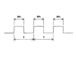
図4を参照して、掃引制御部30は、セレクタ32、遅延器34、幅設定器35、AND演算子36、セレクタ38を有する。セレクタ32は、IFトリガ信号、外部トリガ信号およびゲート信号を受け、いずれか一つを出力する。ただし、ゲート信号の立ち上がりは、搬送波CW1、CW2、CW3の存在する区間の開始時点とする。また、図5に示すように、ゲート信号は所定の周期TでHigh、Lowを繰り返し、Highになっている幅Whは一定である。遅延器34は上記の実施形態と同様である。幅設定器35は、ゲート信号がHighになる幅Whを利用者が設定するためのものである。AND演算子36は上記の実施形態と同様である。セレクタ38は、幅設定器35の出力またはAND演算子36の出力を選択して出力する。
【0043】
セレクタ32によりIFトリガ信号あるいは外部トリガ信号を選択した場合は、セレクタ38はAND演算子36の出力を選択する。この場合は、上記の実施形態のように、周波数掃引を行う区間の幅は自動的に決定される。
【0044】
セレクタ32によりゲート信号を選択した場合は、セレクタ38は幅設定器35の出力を選択する。この場合は、Δtのみならず周波数掃引を行う区間の幅Whをも利用者が設定できる。
【0045】
また、上記の実施形態は、以下のようにして実現できる。CPU、ハードディスク、メディア(フロッピー(登録商標)ディスク、CD−ROMなど)読み取り装置を備えたコンピュータのメディア読み取り装置に、上記の各部分、例えば掃引制御部30を実現するプログラムを記録したメディアを読み取らせて、ハードディスクにインストールする。このような方法でも、上記の機能を実現できる。
【図面の簡単な説明】
【図1】本発明の実施形態にかかるスペクトラムアナライザ(信号測定装置)1の構成を示すブロック図である。
【図2】掃引制御部30の構成を示すブロック図である。
【図3】本発明の実施形態の動作を示すタイムチャートである。
【図4】本発明の実施形態の変形例における掃引制御部30の構成を示すブロック図である。
【図5】本発明の実施形態の変形例におけるゲート信号を示す図である。
【符号の説明】
1 スペクトラムアナライザ(信号測定装置)
10 ローカル発振器
12 ミキサ(混合手段)
14 周波数掃引部
18 中間周波数フィルタ
20 検波器
22 表示器
24 トリガ生成部
30 掃引制御部
32 セレクタ
34 遅延器
35 幅設定器
36 AND演算子
38 セレクタ[0001]
TECHNICAL FIELD OF THE INVENTION
The present invention relates to measurement of a frequency component of a signal to be measured, and more particularly, to frequency sweep at the time of measurement.
[0002]
[Prior art]
2. Description of the Related Art Conventionally, a device that measures a frequency component of a signal to be measured is known as a spectrum analyzer. The spectrum analyzer performs a frequency sweep while receiving the signal to be measured. Thereby, the spectrum analyzer measures the frequency component of the signal to be measured.
[0003]
When the signal to be measured is a carrier in a burst wave, it is assumed that the frequency sweep is continuously performed while receiving the signal of the burst wave. In this case, not only the frequency component of the carrier wave in the burst wave but also the frequency component of the modulated wave in the burst wave are measured.
[0004]
Therefore, in order to measure the frequency component of the carrier in the burst wave, the frequency sweep may be performed only while the carrier in the burst wave exists. This is called a gated sweep. In the gated sweep, a gate signal that is high only while a carrier is present is supplied to a spectrum analyzer, and a frequency sweep is performed when the gate signal is high.
[0005]
In the gated sweep, it may be possible to further set the rising time of the gate signal and the width in which the gate signal is High (for example, see Patent Document 1). Such a gated sweep is particularly referred to as a delayed gated sweep.
[0006]
[Patent Document 1]
JP-A-5-60809 [Problems to be solved by the invention]
However, in the above-described conventional technique, the width at which the gate signal is High is fixed during the measurement. Therefore, it is not suitable for measuring a signal in which the width of a carrier in a burst wave changes, such as a signal in which the slot width changes.
[0007]
Therefore, an object of the present invention is to control the width of a signal for controlling frequency sweep in accordance with a signal to be measured.
[0008]
[Means for Solving the Problems]
According to the first aspect of the present invention, a local signal generating means for generating a local signal, a mixing means for mixing a signal to be measured and a local signal, a frequency sweeping means for sweeping a frequency of the local signal, and a signal to be measured And a sweep control means for stopping the sweep when the existence section of the end is completed.
[0009]
According to the invention configured as described above, the local signal generation unit generates a local signal. The mixing means mixes the signal to be measured and the local signal. The frequency sweep means sweeps the frequency of the local signal. The sweep control means stops the sweep when the existing section of the signal to be measured ends.
[0010]
The invention according to claim 2 is the invention according to
[0011]
A third aspect of the present invention is the invention according to the second aspect, further comprising an intermediate frequency filter for extracting a component of a predetermined frequency band from the mixing means, wherein a trigger signal is generated based on an output of the intermediate frequency filter. It is configured to be.
[0012]
The invention according to claim 4 is the invention according to claim 2 or 3, wherein the sweep control means calculates a logical product of a delay means for delaying the trigger signal, an output of the delay means, and the trigger signal. And a logical product output means for outputting the data, and whether or not to stop the sweep is determined based on the logical product output means.
[0013]
The invention according to claim 5 is the invention according to any one of
[0014]
The invention according to claim 6 is the invention according to claim 5, wherein the widths of the existing sections of the carrier are different.
[0015]
According to a seventh aspect of the present invention, there is provided a local signal generating step of generating a local signal, a mixing step of mixing the measurement target signal and the local signal, a frequency sweeping step of sweeping the frequency of the local signal, and a measurement target signal. And a sweep control step of stopping the sweep when the existence section of has ended.
[0016]
The invention according to claim 8 is a signal comprising: a local signal generating means for generating a local signal; a mixing means for mixing the signal to be measured with the local signal; and a frequency sweeping means for sweeping the frequency of the local signal. This is a program for causing a computer to execute a signal measurement process in the measurement apparatus, and is a program for causing the computer to execute a sweep control process for stopping a sweep when an existing section of a signal to be measured ends.
[0017]
According to a ninth aspect of the present invention, there is provided a signal having local signal generating means for generating a local signal, mixing means for mixing a signal to be measured and a local signal, and frequency sweep means for sweeping the frequency of the local signal. A computer-readable recording medium that records a program for causing a computer to execute a signal measurement process in a measurement device, and causes the computer to execute a sweep control process that stops a sweep when an existing section of a signal to be measured ends. Computer-readable recording medium on which a program for recording is recorded.
[0018]
BEST MODE FOR CARRYING OUT THE INVENTION
Hereinafter, embodiments of the present invention will be described with reference to the drawings.
[0019]
FIG. 1 is a block diagram showing a configuration of a spectrum analyzer (signal measurement device) 1 according to an embodiment of the present invention. The spectrum analyzer (signal measurement device) 1 includes a local oscillator 10, a mixer (mixing means) 12, a
[0020]
The local oscillator 10 generates a local signal.
[0021]
The mixer (mixing means) 12 is a multiplier that mixes and outputs the signal to be measured and the local signal. As shown in FIG. 3, the signals to be measured are the carrier waves CW1, CW2, and CW3 in the burst wave. Moreover, the widths (t12-t10, t22-t20, t32-t30) of the sections of the burst wave where the carrier waves CW1, CW2, CW3 exist are different. The purpose of the
[0022]
The
[0023]
The
[0024]
The
[0025]
The
[0026]
Based on the output of the intermediate frequency filter 18 (for example, performing waveform shaping), the
[0027]
The
[0028]
FIG. 2 is a block diagram illustrating a configuration of the
[0029]
The
[0030]
The
[0031]
The AND
[0032]
Next, the operation of the embodiment of the present invention will be described with reference to the time chart of FIG.
[0033]
First, the signal to be measured is a burst wave, and the purpose of the
[0034]
The signal to be measured is mixed by the
[0035]
The IF trigger signal and the external trigger signal are provided to the
[0036]
Here, it should be noted that the sweep of the frequency of the local signal ends when the section in which the carrier waves CW1, CW2, and CW3, which are t12, t22, and t32, ends. In addition, the sweep of the frequency of the local signal is started when the interval of the carrier waves CW1, CW2, and CW3 called t11, t21, and t31 is delayed by Δt from the start.
[0037]
In this way, the local signal is frequency swept. Then, the signal extracted by the
[0038]
According to the embodiment of the present invention, even if the widths of the sections where the carrier waves CW1, CW2, and CW3 are present in the burst wave are different, the frequency sweep of the local signal is performed at the existence of the carrier waves CW1, CW2, and CW3 of t12, t22, and t32. It ends when the section to be completed ends. Therefore, it is possible to prevent the spectrum of the modulated wave portion other than the carrier waves CW1, CW2, and CW3 from being mixed into the spectrum of the measurement target signal displayed on the
[0039]
In addition, the sweep of the frequency of the local signal starts when the section where the carrier waves CW1, CW2, and CW3 are present is delayed by Δt from the start. Therefore, it is possible to prevent the transient response of the
[0040]
In the present embodiment, the width of the section in which the frequency sweep is performed is not set by the user of the
[0041]
FIG. 4 is a block diagram illustrating a configuration of the
[0042]
Referring to FIG. 4,
[0043]
When the
[0044]
When the gate signal is selected by the
[0045]
Further, the above embodiment can be realized as follows. The above-described parts, for example, a medium recording a program for realizing the
[Brief description of the drawings]
FIG. 1 is a block diagram showing a configuration of a spectrum analyzer (signal measurement device) 1 according to an embodiment of the present invention.
FIG. 2 is a block diagram showing a configuration of a
FIG. 3 is a time chart showing an operation of the embodiment of the present invention.
FIG. 4 is a block diagram illustrating a configuration of a
FIG. 5 is a diagram showing a gate signal in a modification of the embodiment of the present invention.
[Explanation of symbols]
1 spectrum analyzer (signal measurement device)
10
14
Claims (9)
測定対象信号と、前記ローカル信号とを混合する混合手段と、
前記ローカル信号の周波数を掃引させる周波数掃引手段と、
前記測定対象信号の存在区間が終了した時に前記掃引を停止する掃引制御手段と、
を備えた信号測定装置。Local signal generating means for generating a local signal;
A signal to be measured, mixing means for mixing the local signal,
Frequency sweeping means for sweeping the frequency of the local signal,
Sweep control means for stopping the sweep when the existence section of the signal to be measured ends,
A signal measuring device comprising:
前記掃引制御手段は、前記測定対象信号の存在区間が終了した時に状態が変化するトリガ信号を受ける、
信号測定装置。The signal measuring device according to claim 1,
The sweep control means receives a trigger signal whose state changes when an existing section of the measurement target signal ends.
Signal measuring device.
前記混合手段から所定の周波数帯域の成分を取り出す中間周波数フィルタを備え、
前記中間周波数フィルタの出力に基づいてトリガ信号が生成されている、
信号測定装置。The signal measuring device according to claim 2,
An intermediate frequency filter that extracts a component of a predetermined frequency band from the mixing unit,
A trigger signal is generated based on an output of the intermediate frequency filter,
Signal measuring device.
前記掃引制御手段は、
前記トリガ信号を遅延させる遅延手段と、
前記遅延手段の出力と、前記トリガ信号との論理積をとって出力する論理積出力手段と、
を備え、
前記論理積出力手段に基づき前記掃引を停止するか否かが決定される、
信号測定装置。The signal measuring device according to claim 2 or 3,
The sweep control means,
Delay means for delaying the trigger signal;
An output of the delay means, and a logical product output means for performing a logical product of the trigger signal and outputting the result.
With
It is determined whether to stop the sweep based on the logical product output means,
Signal measuring device.
前記測定対象信号は、バースト波中の搬送波である、
信号測定装置。The signal measuring device according to any one of claims 1 to 4,
The signal to be measured is a carrier in a burst wave,
Signal measuring device.
前記搬送波の存在区間の幅が異なる、
信号測定装置。The signal measuring device according to claim 5,
The width of the existing section of the carrier is different;
Signal measuring device.
測定対象信号と、前記ローカル信号とを混合する混合工程と、
前記ローカル信号の周波数を掃引させる周波数掃引工程と、
前記測定対象信号の存在区間が終了した時に前記掃引を停止する掃引制御工程と、
を備えた信号測定方法。A local signal generation step of generating a local signal;
A signal to be measured and a mixing step of mixing the local signal,
A frequency sweeping step of sweeping the frequency of the local signal,
A sweep control step of stopping the sweep when the existence section of the measurement target signal ends,
A signal measurement method comprising:
前記測定対象信号の存在区間が終了した時に前記掃引を停止する掃引制御処理、
をコンピュータに実行させるためのプログラム。A signal measurement process in a signal measurement device including a local signal generation unit that generates a local signal, a measurement target signal, a mixing unit that mixes the local signal, and a frequency sweeping unit that sweeps a frequency of the local signal. A program to be executed by a computer,
Sweep control processing for stopping the sweep when the existence section of the signal to be measured ends,
A program for causing a computer to execute.
前記測定対象信号の存在区間が終了した時に前記掃引を停止する掃引制御処理、
をコンピュータに実行させるためのプログラムを記録したコンピュータによって読み取り可能な記録媒体。A signal measurement process in a signal measurement device including a local signal generation unit that generates a local signal, a measurement target signal, a mixing unit that mixes the local signal, and a frequency sweeping unit that sweeps a frequency of the local signal. A computer-readable recording medium recording a program to be executed by the computer,
Sweep control processing for stopping the sweep when the existence section of the signal to be measured ends,
And a computer-readable recording medium recording a program for causing a computer to execute the program.
Priority Applications (4)
| Application Number | Priority Date | Filing Date | Title |
|---|---|---|---|
| JP2003137471A JP2004347321A (en) | 2003-05-15 | 2003-05-15 | Signal measuring apparatus, method, program, and recording medium |
| PCT/JP2004/006711 WO2004102214A1 (en) | 2003-05-15 | 2004-05-12 | Signal measuring device |
| US10/556,354 US20060286953A1 (en) | 2003-05-15 | 2004-05-12 | Signal measuring device |
| DE112004000798T DE112004000798T5 (en) | 2003-05-15 | 2004-05-12 | Signal measurement device |
Applications Claiming Priority (1)
| Application Number | Priority Date | Filing Date | Title |
|---|---|---|---|
| JP2003137471A JP2004347321A (en) | 2003-05-15 | 2003-05-15 | Signal measuring apparatus, method, program, and recording medium |
Publications (1)
| Publication Number | Publication Date |
|---|---|
| JP2004347321A true JP2004347321A (en) | 2004-12-09 |
Family
ID=33447257
Family Applications (1)
| Application Number | Title | Priority Date | Filing Date |
|---|---|---|---|
| JP2003137471A Withdrawn JP2004347321A (en) | 2003-05-15 | 2003-05-15 | Signal measuring apparatus, method, program, and recording medium |
Country Status (4)
| Country | Link |
|---|---|
| US (1) | US20060286953A1 (en) |
| JP (1) | JP2004347321A (en) |
| DE (1) | DE112004000798T5 (en) |
| WO (1) | WO2004102214A1 (en) |
Cited By (2)
| Publication number | Priority date | Publication date | Assignee | Title |
|---|---|---|---|---|
| WO2008114602A1 (en) * | 2007-03-20 | 2008-09-25 | Advantest Corporation | Test equipment and electronic device |
| JP2021067598A (en) * | 2019-10-25 | 2021-04-30 | アンリツ株式会社 | Signal analyzer and signal analysis method |
Families Citing this family (1)
| Publication number | Priority date | Publication date | Assignee | Title |
|---|---|---|---|---|
| US7714564B2 (en) * | 2008-01-16 | 2010-05-11 | Agilent Technologies, Inc. | Gated sweep in spectrum analyzers |
Family Cites Families (5)
| Publication number | Priority date | Publication date | Assignee | Title |
|---|---|---|---|---|
| US2926304A (en) * | 1958-04-21 | 1960-02-23 | Itt | Frequency determining system |
| JPH0611480Y2 (en) * | 1986-05-22 | 1994-03-23 | 株式会社アドバンテスト | Spectrum analyzer |
| US5038096A (en) * | 1989-07-28 | 1991-08-06 | Hewlett-Packard Company | Spectrum analyzer circuit for pulsed input signals |
| EP0555491B1 (en) * | 1991-09-02 | 1998-12-09 | Advantest Corporation | Spectrum analyzer |
| JPH0714389U (en) * | 1993-08-17 | 1995-03-10 | 株式会社アドバンテスト | Spectrum analyzer |
-
2003
- 2003-05-15 JP JP2003137471A patent/JP2004347321A/en not_active Withdrawn
-
2004
- 2004-05-12 US US10/556,354 patent/US20060286953A1/en not_active Abandoned
- 2004-05-12 DE DE112004000798T patent/DE112004000798T5/en not_active Withdrawn
- 2004-05-12 WO PCT/JP2004/006711 patent/WO2004102214A1/en not_active Ceased
Cited By (2)
| Publication number | Priority date | Publication date | Assignee | Title |
|---|---|---|---|---|
| WO2008114602A1 (en) * | 2007-03-20 | 2008-09-25 | Advantest Corporation | Test equipment and electronic device |
| JP2021067598A (en) * | 2019-10-25 | 2021-04-30 | アンリツ株式会社 | Signal analyzer and signal analysis method |
Also Published As
| Publication number | Publication date |
|---|---|
| US20060286953A1 (en) | 2006-12-21 |
| WO2004102214A1 (en) | 2004-11-25 |
| DE112004000798T5 (en) | 2006-05-04 |
Similar Documents
| Publication | Publication Date | Title |
|---|---|---|
| JP2004347321A (en) | Signal measuring apparatus, method, program, and recording medium | |
| JP2794531B2 (en) | Method for measuring pulsed electron spin resonance signal and electron spin resonance type pulse spectrometer | |
| JP2004347320A (en) | Display and method for measuring and displaying signal | |
| JP2005197813A (en) | Noise eliminating apparatus and receiver | |
| JP4955196B2 (en) | AC signal measuring device | |
| JP3486015B2 (en) | Method and apparatus for generating trigger of FFT analyzer | |
| JP6484263B2 (en) | Screen split display device, measuring device including the same, and screen split display method | |
| JP4103675B2 (en) | Radar equipment | |
| JP3720280B2 (en) | FM-CW radar apparatus and interference wave elimination method in the apparatus | |
| JP4424827B2 (en) | FM-CW radar equipment | |
| JP2007033171A (en) | Frequency component measuring device | |
| JP3088586B2 (en) | Ultrasound diagnostic equipment | |
| JPH09196977A (en) | Spectrum analyzer | |
| JP2009115610A (en) | Device for measuring spectrum, and method of measuring spectrum | |
| JPH0374341B2 (en) | ||
| JP2008309682A (en) | Method for adjusting phase relationship between signals in measuring apparatus, and measuring apparatus | |
| JPH1168444A (en) | Method and device for measuring amplitude/phase of many inputs | |
| JP2001042032A (en) | Radar apparatus signal detection method and its detection apparatus | |
| JP2001249149A (en) | Signal analyzer | |
| JP4787470B2 (en) | Method of operating image display apparatus and image display apparatus | |
| JP2018201599A (en) | Noise suppression device, measurement system, noise suppression method and program | |
| JPH0324489A (en) | Sonar receiver | |
| JP3053639B2 (en) | BS tuner keyed AFC characteristic measuring device | |
| KR20240162433A (en) | Apparatus and Method for Amplifying Fine Signal using Frequency Conversion | |
| JPH09257900A (en) | Resonance frequency setting method for pulse ESR measurement |
Legal Events
| Date | Code | Title | Description |
|---|---|---|---|
| A621 | Written request for application examination |
Free format text: JAPANESE INTERMEDIATE CODE: A621 Effective date: 20060407 |
|
| A761 | Written withdrawal of application |
Free format text: JAPANESE INTERMEDIATE CODE: A761 Effective date: 20081030 |